EP2066989B1 - A ice bank fixation devicing for refrigerator and a refrigerator comprising the same - Google Patents
A ice bank fixation devicing for refrigerator and a refrigerator comprising the same Download PDFInfo
- Publication number
- EP2066989B1 EP2066989B1 EP07808203.9A EP07808203A EP2066989B1 EP 2066989 B1 EP2066989 B1 EP 2066989B1 EP 07808203 A EP07808203 A EP 07808203A EP 2066989 B1 EP2066989 B1 EP 2066989B1
- Authority
- EP
- European Patent Office
- Prior art keywords
- ice bank
- coupling part
- ice
- refrigerator door
- refrigerator
- Prior art date
- Legal status (The legal status is an assumption and is not a legal conclusion. Google has not performed a legal analysis and makes no representation as to the accuracy of the status listed.)
- Active
Links
Images

Classifications
-
- F—MECHANICAL ENGINEERING; LIGHTING; HEATING; WEAPONS; BLASTING
- F25—REFRIGERATION OR COOLING; COMBINED HEATING AND REFRIGERATION SYSTEMS; HEAT PUMP SYSTEMS; MANUFACTURE OR STORAGE OF ICE; LIQUEFACTION SOLIDIFICATION OF GASES
- F25D—REFRIGERATORS; COLD ROOMS; ICE-BOXES; COOLING OR FREEZING APPARATUS NOT OTHERWISE PROVIDED FOR
- F25D23/00—General constructional features
- F25D23/02—Doors; Covers
- F25D23/04—Doors; Covers with special compartments, e.g. butter conditioners
-
- F—MECHANICAL ENGINEERING; LIGHTING; HEATING; WEAPONS; BLASTING
- F25—REFRIGERATION OR COOLING; COMBINED HEATING AND REFRIGERATION SYSTEMS; HEAT PUMP SYSTEMS; MANUFACTURE OR STORAGE OF ICE; LIQUEFACTION SOLIDIFICATION OF GASES
- F25C—PRODUCING, WORKING OR HANDLING ICE
- F25C1/00—Producing ice
- F25C1/22—Construction of moulds; Filling devices for moulds
- F25C1/24—Construction of moulds; Filling devices for moulds for refrigerators, e.g. freezing trays
-
- F—MECHANICAL ENGINEERING; LIGHTING; HEATING; WEAPONS; BLASTING
- F25—REFRIGERATION OR COOLING; COMBINED HEATING AND REFRIGERATION SYSTEMS; HEAT PUMP SYSTEMS; MANUFACTURE OR STORAGE OF ICE; LIQUEFACTION SOLIDIFICATION OF GASES
- F25C—PRODUCING, WORKING OR HANDLING ICE
- F25C5/00—Working or handling ice
- F25C5/02—Apparatus for disintegrating, removing or harvesting ice
-
- F—MECHANICAL ENGINEERING; LIGHTING; HEATING; WEAPONS; BLASTING
- F25—REFRIGERATION OR COOLING; COMBINED HEATING AND REFRIGERATION SYSTEMS; HEAT PUMP SYSTEMS; MANUFACTURE OR STORAGE OF ICE; LIQUEFACTION SOLIDIFICATION OF GASES
- F25C—PRODUCING, WORKING OR HANDLING ICE
- F25C5/00—Working or handling ice
- F25C5/18—Storing ice
-
- F—MECHANICAL ENGINEERING; LIGHTING; HEATING; WEAPONS; BLASTING
- F25—REFRIGERATION OR COOLING; COMBINED HEATING AND REFRIGERATION SYSTEMS; HEAT PUMP SYSTEMS; MANUFACTURE OR STORAGE OF ICE; LIQUEFACTION SOLIDIFICATION OF GASES
- F25C—PRODUCING, WORKING OR HANDLING ICE
- F25C5/00—Working or handling ice
- F25C5/18—Storing ice
- F25C5/182—Ice bins therefor
- F25C5/185—Ice bins therefor with freezing trays
-
- F—MECHANICAL ENGINEERING; LIGHTING; HEATING; WEAPONS; BLASTING
- F25—REFRIGERATION OR COOLING; COMBINED HEATING AND REFRIGERATION SYSTEMS; HEAT PUMP SYSTEMS; MANUFACTURE OR STORAGE OF ICE; LIQUEFACTION SOLIDIFICATION OF GASES
- F25D—REFRIGERATORS; COLD ROOMS; ICE-BOXES; COOLING OR FREEZING APPARATUS NOT OTHERWISE PROVIDED FOR
- F25D25/00—Charging, supporting, and discharging the articles to be cooled
Definitions
- Embodiments relate to a refrigerator including the ice bank fixation device.
- refrigerators are used to keep food at a low temperature.
- a refrigerator includes a body in which a storage chamber is formed, and a door attached to the body for opening/closing the storage chamber.
- An icemaker and an ice bank can be provided in the storage chamber for making and storing ice.
- the ice bank includes an ice carriage lever and an ice carriage motor.
- the ice carriage lever is driven by the ice carriage motor for moving the ice stored in the ice bank to a dispenser.
- the storage capacity of the storage chamber may be reduced due to the ice bank.
- the ice stored in the ice bank can be discharged only through the dispenser using the ice carriage lever. That is, a user cannot eject the ice directly from the ice bank.
- a refrigerator comprising an ice bank is known from US6442954 .
- Embodiments provide a refrigerator including the ice bank fixation device so that a storage chamber of the refrigerator can be less occupied by an ice bank.
- Embodiments also provide a refrigerator including the ice bank fixation device that allows a user to take ice automatically or manually from an ice bank.
- the solution to the problem is a refrigerator according to claim 1.
- the ice bank is attached to the backside of the re-frigerator door so that the ice bank may occupy less of a storage chamber of the re-frigerator, and thus more food can be stored in the storage chamber.
- the ice bank can be attached to and detached from the refrigerator door more easily owing to the ice bank fixation device, and thus a user can take ice automatically from the ice bank through a dispenser or manually from the ice bank after detaching the ice bank from the backside of the refrigerator door.
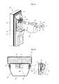
- Fig. 1 is a perspective view illustrating an ice bank 60 detached from a refrigerator door 50 according to a first embodiment
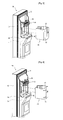
- Figs. 2 to 4 are views for explaining how the ice bank 60 is detached from the refrigerator door 50.
- the refrigerator door 50 of the current embodiment includes a dispenser 51.
- the dispenser 51 allows a user to get water or ice without opening the refrigerator door 50 (i.e., without opening a storage space of a refrigerator).
- An outer door 53 is formed on a front outer portion of the refrigerator door 50.
- a door liner 55 is coupled to an inner surface of the outer door 53 to form the backside of the refrigerator door 50.
- Supports 56 are formed on both sides of the backside of the refrigerator door 50. The supports 56 extend backward from the door liner 55 and have a vertically elongated shape.
- At least one pair of second coupling parts 57 is formed at mutually facing surfaces of the supports 56.
- the second coupling parts 57 are formed for receiving first coupling parts 71 (described later).
- the second coupling parts 57 are formed at corresponding positions of the mutually facing surfaces of the supports 56.
- the second coupling parts 57 may be recesses formed in the mutually facing surfaces of the supports 56.
- a receiving surface 58 is formed at the backside of the refrigerator door 50.
- the receiving surface 58 is formed by backwardly extending a portion of the door liner 55 located between the supports 56.
- the receiving surface 58 extends backward more than the supports 56.
- the receiving surface 58 includes an opening 59. Ice stored in an ice storage space 60S (described later) of the ice bank 60 is carried to the dispenser 51 through the opening 59.
- the ice bank 60 and an icemaker 40 are detachably coupled to the backside of the refrigerator door 50.
- the icemaker 40 is disposed above the ice bank 60.
- both sides of the ice bank 60 make tight contact with the mutually facing surfaces of the supports 56, and a bottom surface of the ice bank 60 makes contact with the receiving surface 58. Therefore, the ice bank 60 can be first fixed in lateral direction by the supports 56.
- Ice produced by the icemaker 40 is stored in the ice storage space 60S of the ice bank 60.
- the ice storage space 60S has an opened top portion.
- the ice stored in the ice storage space 60S of the ice bank 60 is carried to the dispenser 51 and discharged to a user through the dispenser 51.
- the ice bank 60 includes an ice outlet 63 in a bottom surface for discharging ice.
- the ice outlet 63 is formed at a position corresponding to the position of the opening 59 of the receiving surface 58.
- An icebreaker 61 is disposed in the ice bank 60 for breaking the ice stored in the ice storage space 60S into parts having a predetermined size and carrying the broken ice to the dispenser 51.
- the icebreaker 61 is disposed above and close to the ice outlet 63.
- An icebreaker motor (not shown) drives the icebreaker 61.
- the icebreaker motor is disposed at a side of the icebreaker 61.
- the icebreaker motor can be disposed at the refrigerator door 50 and connected to the icebreaker 61 through an additional linkage member.
- the ice outlet 63 is closed or opened according to the operation of the icebreaker 61.
- ice stored in the ice storage space 60S is carried to the dispenser 51 through the ice outlet 63 and the opening 59.
- the ice outlet 63 is substantially closed by the icebreaker 61.
- the icebreaker 61 includes a window 65.
- the window 65 is formed of a transparent or semitransparent material. Therefore, a user can check the amount of ice stored in the ice storage space 60S through the window 65.
- Rotation spaces 67 are formed in both sides of the ice bank 60 to allow rotation of the first coupling parts 71.
- the rotation spaces 67 may be recesses formed in both sides of the ice bank 60.
- the number of the first coupling parts 71 of the ice bank 60 is at least two (a pair), and the first coupling parts 71 are rotatably disposed in the rotation spaces 67, respectively.
- the first coupling parts 71 are coupled to the second coupling parts 57 so that the ice bank 60 can be stably locked on the backside of the refrigerator door 50.
- Both ends of each of the first coupling parts 71 can be rotated about a shaft 71H that is vertically disposed in the rotation space 67.
- shafts can be integrally formed on the first coupling parts 71, respectively, and insertion holes can be formed in the ice bank 60 for receiving the shafts.
- Coupling tabs 73 extend outward from front ends of the first coupling parts 71 that are adjacent to the backside of the refrigerator door 50.
- the coupling tab 73 can be inserted into the second coupling parts 57 by rotating the first coupling parts 71 about the shafts 71H.
- Guide surfaces 74 are formed on outer surfaces of the coupling tabs 73, respectively.
- the guide surfaces 74 can have a rounded shape.
- Levers 75 are formed on rear ends of the first coupling parts 71. A user can pull the levers 75 to rotate the first coupling parts 71 on the shafts 71H.
- the levers 75 can be curved from the rear ends of the first coupling parts 71 away from the ice bank 60 so as to be placed outside the rotation spaces 67.
- the levers 75 are protruded outward from the ice bank 60 so that a user can pull the levers 75.
- Torsion springs 77 are disposed at the shafts 71H, respectively.
- One end of the torsion spring 77 is supported by a side of the ice bank 60, and the other end of the torsion spring 77 is supported by a side of the first coupling part 71.
- the torsion spring 77 elastically forces the coupling tab 73 to rotate into the second coupling part 57.
- one end of the torsion spring 77 can be supported by the ceiling of the rotation space 67, and the other end of the torsion spring 77 can be supported by the front end of the first coupling part 71.
- the coupling tabs 73 are inserted into the second coupling parts 57.
- the coupling tabs 73 can be stably held in the second coupling parts 57 owing to the torsion springs 77.
- the ice bank 60 is not unintentionally detached from the backside of the refrigerator door 50.
- the icebreaker 61 operates to discharge ice stored in the ice storage space 60S of the ice bank 60 to the outside through the dispenser 51. Therefore, the user can get ice without opening the refrigerator door 50.
- the ice bank 60 can be detached from the refrigerator door 50 by disengaging the first coupling parts 71 from the second coupling parts 57 as shown in Fig. 3 .
- a user pulls the levers 75 away from the ice bank 60. That is, the user pulls the levers 75 to rotate the right-side first coupling part 71 counterclockwise and the left-side first coupling part 71 clockwise about the shafts 71H, respectively.
- the coupling tabs 73 are disengaged from the second coupling parts 57, and thus the first coupling parts 71 are disengaged from the second coupling parts 57.
- the ice bank 60 can be detached from the backside of the refrigerator door 50 by pulling the ice bank 60 away from the backside of the refrigerator door 50 as shown in Fig. 4 . Therefore, a user can take ice directly from the ice storage space 60S of the ice bank 60.
- the first coupling parts 71 can rotate to their original positions by releasing the levers 75. Since the ice outlet 63 of the ice bank 60 is screened by the icebreaker 61, ice is not undesirably discharged through the ice outlet 63.
- the detached ice bank 60 can be attached to the backside of the refrigerator door 50 again by repeating the above-described procedures in a reverse order. In this case, it is not necessary to pull the levers 75.
- the ice bank 60 is directly attached to the backside of the refrigerator door 50.
- other structures can be used for attaching the ice bank 60 to the refrigerator door 50.
- an additional accommodation member can be disposed to the backside of the refrigerator door 50, and the ice bank 60 and the icemaker 40 can be attached to the accommodation member.
- the second coupling parts 57 are formed at the refrigerator door 50, and the first coupling parts 71 are formed at the ice bank 60 in the current embodiment.
- the second coupling parts 57 can be formed at the ice bank 60, and the first coupling parts 71 can be formed at the refrigerator door 50.
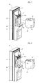
- Fig. 5 is a perspective view illustrating an ice bank 60 detached from a refrigerator door 50 according to a second embodiment, not forming part of the present invention.
- an ice bank fixation device of the current embodiment includes a plurality of coupling protrusions 81 formed on the refrigerator door 50 and a plurality of protrusion insertion holes 82 formed in the ice bank 60 for coupling with the coupling protrusions 81.
- the coupling protrusions 81 are formed on supports 56.
- the coupling protrusions 81 can be vertically arranged on the supports 56.
- the protrusion insertion holes 82 are formed in the ice bank 60 at positions corresponding to those of the coupling protrusions 81.
- the coupling protrusions 81 are inserted into the protrusion insertion holes 82 so that the ice bank 60 can be fully fixed to the refrigerator door 50.
- the coupling protrusions 81 are formed on the refrigerator door 50, and the protrusion insertion holes 82 are formed in the ice bank 60.
- the coupling protrusions 81 can be formed on the ice bank 60, and the protrusion insertion holes 82 can be formed in the refrigerator door 50.
- Fig. 6 is a perspective view illustrating an ice bank 60 detached from a refrigerator door 50 according to a third embodiment, not forming part of the present invention.
- an ice bank fixation device of the current embodiment includes a plurality of first coupling parts 85 formed on the ice bank 60, and a plurality of second coupling parts 86 formed on supports 56 of the refrigerator door 50 for coupling with the first coupling part 85 by sliding.
- first coupling parts 85 can have a horizontally elongated shape and arranged in a vertical direction.
- the second coupling parts 86 can have a horizontally elongated recess shape and arranged in a vertical direction.
- the first coupling parts 85 can slide into the second coupling part 86 by pushing the ice bank 60 toward the refrigerator door 50 after aligning the first coupling parts 85 with the second coupling parts 86. In this way, the ice bank 60 can be coupled to the refrigerator door 50.
- the first coupling parts 85 have a size corresponding to that of the second coupling parts 86, and the first and second coupling parts 85 and 86 are arranged in a vertical direction. Therefore, after the ice bank 60 is coupled to the refrigerator door 50, the ice bank 60 is not readily detached from the refrigerator door 50 when the refrigerator door 50 is opened and closed.
- Fig. 7 is a perspective view illustrating an ice bank 60 detached from a refrigerator door 50 according to a fourth embodiment, not forming part of the present invention.
- an ice bank fixation device of the current embodiment includes at least one magnetic member 91 disposed at the ice bank 60 and a metal member 92 disposed at the refrigerator door 50 for coupling with the magnetic member 91.
- the magnetic member 91 can be disposed on at least one portion of the ice bank 60.
- two magnetic members 91 are disposed on bottom and front surfaces of the ice bank 60.
- the metal member 92 is disposed at a position corresponding to that of the magnetic member 91.
- a structure for attaching the ice bank 60 to the refrigerator door 50 is not exposed to the outside for aesthetical improvement.
- the ice bank 60 When the ice bank 60 is attached to the refrigerator door 50, the ice bank 60 makes contact with a door liner 55 of the refrigerator door 50.
- the door liner 55 is formed of a material to which the magnetic member 91 can be magnetically attached, the metal member 92 can be omitted from the refrigerator door 50.
- the metal member 92 can be disposed at a bottom surface of an icemaker 40.
- the magnetic member 91 may be disposed on a top portion of the ice bank 60. Therefore, the refrigerator door 50 can be placed on a receiving surface 58 and firmly held at that position by a magnetic force between the metal member 92 of the icemaker 40 and the magnetic member 91 of the ice bank 60.
- Fig. 8 is a perspective view illustrating an ice bank 60 detached from a refrigerator door 50 according to a fifth embodiment, not forming part of the present invention.
- an ice bank fixation device of the current embodiment includes a latch hook 95 formed on the ice bank 60 and a latch slot 96 formed in the refrigerator door 50 for receiving the latch hook 95.
- the latch hook 95 may be formed at a front side of the ice bank 60 for easy coupling with the latch slot 96.
- the latch hook 95 can be coupled to the latch slot 96 by pushing the latch hook 95 against the latch slot 96, and the latch hook 95 can be released from the latch slot 96 by pushing the latch hook 95 against the latch slot 96 again. Since this coupling structure is well known, a detailed description thereof will be omitted.
- the latch slot 96 can be formed in the ice bank 60, and the latch hook 95 can be formed on the refrigerator door 50.
- an ice bank can be detachably attached to a refrigerator door using the ice bank fixation device. Therefore, a user can take ice automatically from the ice bank through a dispenser or manually from the ice bank after detaching the ice bank from the backside of the refrigerator door, and thus the refrigerator including the ice bank fixation device can be used in various industrial fields.
Landscapes
- Engineering & Computer Science (AREA)
- Physics & Mathematics (AREA)
- Mechanical Engineering (AREA)
- Thermal Sciences (AREA)
- General Engineering & Computer Science (AREA)
- Chemical & Material Sciences (AREA)
- Combustion & Propulsion (AREA)
- Refrigerator Housings (AREA)
- Devices That Are Associated With Refrigeration Equipment (AREA)
Description
- Embodiments relate to a refrigerator including the ice bank fixation device.
- Generally, refrigerators are used to keep food at a low temperature. Such a refrigerator includes a body in which a storage chamber is formed, and a door attached to the body for opening/closing the storage chamber.
- An icemaker and an ice bank can be provided in the storage chamber for making and storing ice. The ice bank includes an ice carriage lever and an ice carriage motor. The ice carriage lever is driven by the ice carriage motor for moving the ice stored in the ice bank to a dispenser.
- In this case, the storage capacity of the storage chamber may be reduced due to the ice bank. Moreover, the ice stored in the ice bank can be discharged only through the dispenser using the ice carriage lever. That is, a user cannot eject the ice directly from the ice bank. A refrigerator comprising an ice bank is known from
US6442954 . - Embodiments provide a refrigerator including the ice bank fixation device so that a storage chamber of the refrigerator can be less occupied by an ice bank.
- Embodiments also provide a refrigerator including the ice bank fixation device that allows a user to take ice automatically or manually from an ice bank.
- The solution to the problem is a refrigerator according to claim 1.
- According to embodiments, the ice bank is attached to the backside of the re-frigerator door so that the ice bank may occupy less of a storage chamber of the re-frigerator, and thus more food can be stored in the storage chamber.
- In addition, the ice bank can be attached to and detached from the refrigerator door more easily owing to the ice bank fixation device, and thus a user can take ice automatically from the ice bank through a dispenser or manually from the ice bank after detaching the ice bank from the backside of the refrigerator door.
- Embodiments can be understood more clearly from the accompanying drawings.
-
Fig. 1 is a perspective view illustrating an ice bank detached from a refrigerator door according to a first embodiment. -
Figs. 2 to 4 are views for explaining how the ice bank is detached from the refrigerator door. -
Fig. 5 is a perspective view illustrating an ice bank detached from a refrigerator door according to a second embodiment, not forming part of the present invention. -
Fig. 6 is a perspective view illustrating an ice bank detached from a refrigerator door according to a third embodiment, not forming part of the present invention. -
Fig. 7 is a perspective view illustrating an ice bank detached from a refrigerator door according to a fourth embodiment, not forming part of the present invention. -
Fig. 8 is a perspective view illustrating an ice bank detached from a refrigerator door according to a fifth embodiment, not forming part of the present invention. - Reference will now be made in detail to the embodiments of the present disclosure, examples of which are illustrated in the accompanying drawings.
-
Fig. 1 is a perspective view illustrating anice bank 60 detached from arefrigerator door 50 according to a first embodiment, andFigs. 2 to 4 are views for explaining how theice bank 60 is detached from therefrigerator door 50. - Referring to
Figs. 1 to 4 , therefrigerator door 50 of the current embodiment includes adispenser 51. Thedispenser 51 allows a user to get water or ice without opening the refrigerator door 50 (i.e., without opening a storage space of a refrigerator). - An
outer door 53 is formed on a front outer portion of therefrigerator door 50. Adoor liner 55 is coupled to an inner surface of theouter door 53 to form the backside of therefrigerator door 50.Supports 56 are formed on both sides of the backside of therefrigerator door 50. The supports 56 extend backward from thedoor liner 55 and have a vertically elongated shape. - At least one pair of
second coupling parts 57 is formed at mutually facing surfaces of thesupports 56. Thesecond coupling parts 57 are formed for receiving first coupling parts 71 (described later). Thesecond coupling parts 57 are formed at corresponding positions of the mutually facing surfaces of thesupports 56. Thesecond coupling parts 57 may be recesses formed in the mutually facing surfaces of thesupports 56. - A receiving
surface 58 is formed at the backside of therefrigerator door 50. Thereceiving surface 58 is formed by backwardly extending a portion of thedoor liner 55 located between thesupports 56. Thereceiving surface 58 extends backward more than thesupports 56. - The
receiving surface 58 includes anopening 59. Ice stored in anice storage space 60S (described later) of theice bank 60 is carried to thedispenser 51 through theopening 59. - The
ice bank 60 and anicemaker 40 are detachably coupled to the backside of therefrigerator door 50. The icemaker 40 is disposed above theice bank 60. - When the
ice bank 60 is coupled to the backside of therefrigerator door 50, both sides of theice bank 60 make tight contact with the mutually facing surfaces of thesupports 56, and a bottom surface of theice bank 60 makes contact with thereceiving surface 58. Therefore, theice bank 60 can be first fixed in lateral direction by thesupports 56. - Ice produced by the
icemaker 40 is stored in theice storage space 60S of theice bank 60. Theice storage space 60S has an opened top portion. - The ice stored in the
ice storage space 60S of theice bank 60 is carried to thedispenser 51 and discharged to a user through thedispenser 51. - In detail, the
ice bank 60 includes anice outlet 63 in a bottom surface for discharging ice. Theice outlet 63 is formed at a position corresponding to the position of the opening 59 of thereceiving surface 58. An icebreaker 61 is disposed in theice bank 60 for breaking the ice stored in theice storage space 60S into parts having a predetermined size and carrying the broken ice to thedispenser 51. The icebreaker 61 is disposed above and close to theice outlet 63. - An icebreaker motor (not shown) drives the
icebreaker 61. The icebreaker motor is disposed at a side of theicebreaker 61. Alternatively, the icebreaker motor can be disposed at therefrigerator door 50 and connected to theicebreaker 61 through an additional linkage member. - The
ice outlet 63 is closed or opened according to the operation of theicebreaker 61. In detail, when theicebreaker 61 operates, ice stored in theice storage space 60S is carried to thedispenser 51 through theice outlet 63 and theopening 59. When theicebreaker 61 does not operate, theice outlet 63 is substantially closed by theicebreaker 61. - The icebreaker 61 includes a
window 65. Thewindow 65 is formed of a transparent or semitransparent material. Therefore, a user can check the amount of ice stored in theice storage space 60S through thewindow 65. -
Rotation spaces 67 are formed in both sides of theice bank 60 to allow rotation of thefirst coupling parts 71. Therotation spaces 67 may be recesses formed in both sides of theice bank 60. - The number of the
first coupling parts 71 of theice bank 60 is at least two (a pair), and thefirst coupling parts 71 are rotatably disposed in therotation spaces 67, respectively. When theice bank 60 is attached to the backside of therefrigerator door 50, thefirst coupling parts 71 are coupled to thesecond coupling parts 57 so that theice bank 60 can be stably locked on the backside of therefrigerator door 50. - Both ends of each of the
first coupling parts 71 can be rotated about ashaft 71H that is vertically disposed in therotation space 67. Alternatively, shafts can be integrally formed on thefirst coupling parts 71, respectively, and insertion holes can be formed in theice bank 60 for receiving the shafts. - Coupling
tabs 73 extend outward from front ends of thefirst coupling parts 71 that are adjacent to the backside of therefrigerator door 50. Thecoupling tab 73 can be inserted into thesecond coupling parts 57 by rotating thefirst coupling parts 71 about theshafts 71H. Guide surfaces 74 are formed on outer surfaces of thecoupling tabs 73, respectively. When theice bank 60 is coupled to the backside of therefrigerator door 50, thecoupling tab 73 can be smoothly inserted into thesecond coupling parts 57 owing to the guide surfaces 74. The guide surfaces 74 can have a rounded shape. -
Levers 75 are formed on rear ends of thefirst coupling parts 71. A user can pull thelevers 75 to rotate thefirst coupling parts 71 on theshafts 71H. For example, thelevers 75 can be curved from the rear ends of thefirst coupling parts 71 away from theice bank 60 so as to be placed outside therotation spaces 67. When theice bank 60 is coupled to therefrigerator door 50, thelevers 75 are protruded outward from theice bank 60 so that a user can pull thelevers 75. - Torsion springs 77 are disposed at the
shafts 71H, respectively. One end of thetorsion spring 77 is supported by a side of theice bank 60, and the other end of thetorsion spring 77 is supported by a side of thefirst coupling part 71. When thefirst coupling part 71 is coupled to thesecond coupling part 57, thetorsion spring 77 elastically forces thecoupling tab 73 to rotate into thesecond coupling part 57. For example, one end of thetorsion spring 77 can be supported by the ceiling of therotation space 67, and the other end of thetorsion spring 77 can be supported by the front end of thefirst coupling part 71. - Hereinafter, an ice bank fixation device, a refrigerator including the ice bank fixation device, and how the
ice bank 60 is attached/detached to/from the refrigerator will be described in detail with reference to the accompanying drawing. - Referring to
Fig. 2 , when theice bank 60 is coupled to the backside of therefrigerator door 50, thecoupling tabs 73 are inserted into thesecond coupling parts 57. Thecoupling tabs 73 can be stably held in thesecond coupling parts 57 owing to the torsion springs 77. - Therefore, the
ice bank 60 is not unintentionally detached from the backside of therefrigerator door 50. - In this state, when a user manipulates the
dispenser 51, theicebreaker 61 operates to discharge ice stored in theice storage space 60S of theice bank 60 to the outside through thedispenser 51. Therefore, the user can get ice without opening therefrigerator door 50. - Meanwhile, the
ice bank 60 can be detached from therefrigerator door 50 by disengaging thefirst coupling parts 71 from thesecond coupling parts 57 as shown inFig. 3 . In detail, a user pulls thelevers 75 away from theice bank 60. That is, the user pulls thelevers 75 to rotate the right-side first couplingpart 71 counterclockwise and the left-side first couplingpart 71 clockwise about theshafts 71H, respectively. Then, thecoupling tabs 73 are disengaged from thesecond coupling parts 57, and thus thefirst coupling parts 71 are disengaged from thesecond coupling parts 57. - In this state, the
ice bank 60 can be detached from the backside of therefrigerator door 50 by pulling theice bank 60 away from the backside of therefrigerator door 50 as shown inFig. 4 . Therefore, a user can take ice directly from theice storage space 60S of theice bank 60. - After the
ice bank 60 is detached from therefrigerator door 50, thefirst coupling parts 71 can rotate to their original positions by releasing thelevers 75. Since theice outlet 63 of theice bank 60 is screened by theicebreaker 61, ice is not undesirably discharged through theice outlet 63. - Meanwhile, the
detached ice bank 60 can be attached to the backside of therefrigerator door 50 again by repeating the above-described procedures in a reverse order. In this case, it is not necessary to pull thelevers 75. - In the current embodiment, the
ice bank 60 is directly attached to the backside of therefrigerator door 50. However, other structures can be used for attaching theice bank 60 to therefrigerator door 50. For example, an additional accommodation member can be disposed to the backside of therefrigerator door 50, and theice bank 60 and theicemaker 40 can be attached to the accommodation member. - In addition, the
second coupling parts 57 are formed at therefrigerator door 50, and thefirst coupling parts 71 are formed at theice bank 60 in the current embodiment. However, thesecond coupling parts 57 can be formed at theice bank 60, and thefirst coupling parts 71 can be formed at therefrigerator door 50. -
Fig. 5 is a perspective view illustrating anice bank 60 detached from arefrigerator door 50 according to a second embodiment, not forming part of the present invention. - Referring to
Fig. 5 , an ice bank fixation device of the current embodiment includes a plurality ofcoupling protrusions 81 formed on therefrigerator door 50 and a plurality of protrusion insertion holes 82 formed in theice bank 60 for coupling with thecoupling protrusions 81. - In detail, the
coupling protrusions 81 are formed on supports 56. The coupling protrusions 81 can be vertically arranged on thesupports 56. The protrusion insertion holes 82 are formed in theice bank 60 at positions corresponding to those of thecoupling protrusions 81. - When the
ice bank 60 is attached to therefrigerator door 50, thecoupling protrusions 81 are inserted into the protrusion insertion holes 82 so that theice bank 60 can be fully fixed to therefrigerator door 50. - In the current embodiment, the
coupling protrusions 81 are formed on therefrigerator door 50, and the protrusion insertion holes 82 are formed in theice bank 60. However, thecoupling protrusions 81 can be formed on theice bank 60, and the protrusion insertion holes 82 can be formed in therefrigerator door 50. -
Fig. 6 is a perspective view illustrating anice bank 60 detached from arefrigerator door 50 according to a third embodiment, not forming part of the present invention. - Referring to
Fig. 6 , an ice bank fixation device of the current embodiment includes a plurality offirst coupling parts 85 formed on theice bank 60, and a plurality ofsecond coupling parts 86 formed onsupports 56 of therefrigerator door 50 for coupling with thefirst coupling part 85 by sliding. - In detail, the
first coupling parts 85 can have a horizontally elongated shape and arranged in a vertical direction. Thesecond coupling parts 86 can have a horizontally elongated recess shape and arranged in a vertical direction. - Therefore, the
first coupling parts 85 can slide into thesecond coupling part 86 by pushing theice bank 60 toward therefrigerator door 50 after aligning thefirst coupling parts 85 with thesecond coupling parts 86. In this way, theice bank 60 can be coupled to therefrigerator door 50. - The
first coupling parts 85 have a size corresponding to that of thesecond coupling parts 86, and the first andsecond coupling parts ice bank 60 is coupled to therefrigerator door 50, theice bank 60 is not readily detached from therefrigerator door 50 when therefrigerator door 50 is opened and closed. -
Fig. 7 is a perspective view illustrating anice bank 60 detached from arefrigerator door 50 according to a fourth embodiment, not forming part of the present invention. - Referring to
Fig. 7 , an ice bank fixation device of the current embodiment includes at least onemagnetic member 91 disposed at theice bank 60 and ametal member 92 disposed at therefrigerator door 50 for coupling with themagnetic member 91. - In detail, the
magnetic member 91 can be disposed on at least one portion of theice bank 60. InFig. 7 , for example, twomagnetic members 91 are disposed on bottom and front surfaces of theice bank 60. Themetal member 92 is disposed at a position corresponding to that of themagnetic member 91. - According to the current embodiment, a structure for attaching the
ice bank 60 to therefrigerator door 50 is not exposed to the outside for aesthetical improvement. - When the
ice bank 60 is attached to therefrigerator door 50, theice bank 60 makes contact with adoor liner 55 of therefrigerator door 50. Thus, in the case where thedoor liner 55 is formed of a material to which themagnetic member 91 can be magnetically attached, themetal member 92 can be omitted from therefrigerator door 50. - Alternatively, the
metal member 92 can be disposed at a bottom surface of anicemaker 40. In this case, themagnetic member 91 may be disposed on a top portion of theice bank 60. Therefore, therefrigerator door 50 can be placed on a receivingsurface 58 and firmly held at that position by a magnetic force between themetal member 92 of theicemaker 40 and themagnetic member 91 of theice bank 60. -
Fig. 8 is a perspective view illustrating anice bank 60 detached from arefrigerator door 50 according to a fifth embodiment, not forming part of the present invention. - Referring to
Fig. 8 , an ice bank fixation device of the current embodiment includes alatch hook 95 formed on theice bank 60 and alatch slot 96 formed in therefrigerator door 50 for receiving thelatch hook 95. Thelatch hook 95 may be formed at a front side of theice bank 60 for easy coupling with thelatch slot 96. - The
latch hook 95 can be coupled to thelatch slot 96 by pushing thelatch hook 95 against thelatch slot 96, and thelatch hook 95 can be released from thelatch slot 96 by pushing thelatch hook 95 against thelatch slot 96 again. Since this coupling structure is well known, a detailed description thereof will be omitted. - Meanwhile, alternatively, the
latch slot 96 can be formed in theice bank 60, and thelatch hook 95 can be formed on therefrigerator door 50. - According to embodiments, an ice bank can be detachably attached to a refrigerator door using the ice bank fixation device. Therefore, a user can take ice automatically from the ice bank through a dispenser or manually from the ice bank after detaching the ice bank from the backside of the refrigerator door, and thus the refrigerator including the ice bank fixation device can be used in various industrial fields.
Claims (3)
- A refrigerator comprising an ice bank fixation device, the ice bank fixation device comprising:a first coupling part formed at an ice bank (60);a second coupling part configured to keep the ice bank (60) at a position attached to a backside of a refrigerator door (50) by an interlocking motion with the first coupling part; andan elastic member applying an elastic force to the first coupling part to rotate the first coupling part (71) for coupling with the second coupling part (57),the second coupling part (57) comprising recesses formed in supports (56) extending backward from both sides of the backside of the refrigerator door,the first coupling part (71) being rotatable on the ice bank,the refrigerator door (50) comprising said supports (56) formed on both sides of the backside thereof, the second coupling part (57) being formed at mutually facing surfaces of the supports,the ice bank (60) comprising a rotation space (67) allowing rotation of the first coupling part,the first coupling part comprising an end extending from a rotation center of the first coupling part for coupling with the second coupling part (57) and a lever (75) on the other end thereof for handling the first coupling part,the lever (75) being curved from the rear end of the first coupling part (71) away from the ice bank so as to be placed outside the rotation space (67).
- A refrigerator according to claim 1, wherein the ice bank fixation device further comprises a shaft (71H) on which the first coupling part rotates, and the first coupling part comprises an end extending away from the shaft and insertable into the second coupling part.
- A refrigerator according to claim 1, wherein the second coupling part is a portion of a door liner (55) forming a backside of the refrigerator door.
Applications Claiming Priority (2)
| Application Number | Priority Date | Filing Date | Title |
|---|---|---|---|
| KR1020060088219A KR100780836B1 (en) | 2006-09-12 | 2006-09-12 | Ice bank fixing device for a refrigerator and a refrigerator including the same |
| PCT/KR2007/004411 WO2008032986A1 (en) | 2006-09-12 | 2007-09-12 | A ice bank fixation devicing for refrigerator and a refrigerator comprising the same |
Publications (3)
| Publication Number | Publication Date |
|---|---|
| EP2066989A1 EP2066989A1 (en) | 2009-06-10 |
| EP2066989A4 EP2066989A4 (en) | 2011-08-31 |
| EP2066989B1 true EP2066989B1 (en) | 2015-12-02 |
Family
ID=39081371
Family Applications (1)
| Application Number | Title | Priority Date | Filing Date |
|---|---|---|---|
| EP07808203.9A Active EP2066989B1 (en) | 2006-09-12 | 2007-09-12 | A ice bank fixation devicing for refrigerator and a refrigerator comprising the same |
Country Status (8)
| Country | Link |
|---|---|
| EP (1) | EP2066989B1 (en) |
| JP (1) | JP5054111B2 (en) |
| KR (1) | KR100780836B1 (en) |
| CN (1) | CN101512259B (en) |
| AU (1) | AU2007295228B2 (en) |
| ES (1) | ES2555779T3 (en) |
| MX (1) | MX2009002724A (en) |
| WO (1) | WO2008032986A1 (en) |
Families Citing this family (22)
| Publication number | Priority date | Publication date | Assignee | Title |
|---|---|---|---|---|
| KR100934185B1 (en) | 2007-10-31 | 2009-12-29 | 엘지전자 주식회사 | Ice making device |
| KR100934186B1 (en) | 2007-12-14 | 2009-12-29 | 엘지전자 주식회사 | Ice bank desorption device for refrigerator |
| EP2235450B1 (en) * | 2007-12-14 | 2024-04-03 | Lg Electronics, Inc. | Refrigerator with an ice bank |
| KR20100037266A (en) * | 2008-10-01 | 2010-04-09 | 삼성전자주식회사 | Refrigerator |
| KR101631322B1 (en) | 2009-12-22 | 2016-06-24 | 엘지전자 주식회사 | Refrigerator |
| KR101621558B1 (en) * | 2009-12-22 | 2016-05-16 | 엘지전자 주식회사 | Refrigerator |
| KR101669421B1 (en) | 2010-04-05 | 2016-10-26 | 삼성전자주식회사 | Refrigerator |
| TR201106341A1 (en) * | 2011-06-27 | 2013-01-21 | Ar�El�K Anon�M ��Rket� | A cooler containing an ice container placed on the door. |
| KR101392927B1 (en) * | 2011-10-17 | 2014-05-14 | 포항공과대학교 산학협력단 | An ice bucket for unlaying ice curdling and refrigerator having the same |
| KR101907167B1 (en) | 2012-04-10 | 2018-10-12 | 삼성전자주식회사 | Refrigerator |
| KR102189239B1 (en) | 2013-05-27 | 2020-12-09 | 삼성전자주식회사 | Refrigerator |
| EP2843326B1 (en) * | 2013-08-27 | 2019-03-20 | Samsung Electronics Co., Ltd. | Refrigerator |
| KR101936889B1 (en) | 2015-01-08 | 2019-01-10 | 삼성전자주식회사 | Refrigerator |
| SI24944A (en) * | 2015-03-06 | 2016-09-30 | Gorenje Gospodinjski Aparati, D.D. | Domestic appliance with storage container, adjustable with door height |
| KR101696850B1 (en) * | 2015-06-17 | 2017-01-16 | 동부대우전자 주식회사 | Refrigerator having locking device for ice burcket and method for installation of locking device of ice burcket |
| KR102373219B1 (en) | 2015-12-10 | 2022-03-17 | 삼성전자주식회사 | Refrigerator |
| CN105674674B (en) * | 2016-02-26 | 2018-03-16 | 合肥华凌股份有限公司 | Mounting structure, refrigerator doors and the refrigerator of ice making machine pf refrigerator |
| CN105627680B (en) * | 2016-02-26 | 2018-04-17 | 合肥华凌股份有限公司 | Mounting structure, refrigerator doors and the refrigerator of refrigerator ice-making hood |
| CN105716358B (en) * | 2016-03-21 | 2018-07-31 | 合肥华凌股份有限公司 | A kind of ice machine built-in fitting and refrigerator |
| CN109323527B (en) * | 2017-07-31 | 2020-09-15 | 合肥华凌股份有限公司 | Control method and device for ice discharging motor, storage medium and refrigerator |
| US11009277B2 (en) * | 2019-05-15 | 2021-05-18 | Haier Us Appliance Solutions, Inc. | Refrigator applicances having a removable ice storage bin |
| US11629902B2 (en) * | 2019-05-21 | 2023-04-18 | Haier Us Appliance Solutions, Inc. | Refrigerator appliance having an ice storage bin |
Family Cites Families (14)
| Publication number | Priority date | Publication date | Assignee | Title |
|---|---|---|---|---|
| US3545217A (en) * | 1969-04-10 | 1970-12-08 | Whirlpool Co | Sensing arm mechanism for icemaker |
| US3602007A (en) * | 1969-10-16 | 1971-08-31 | Gen Electric | Refrigerator including through-the-door ice service |
| US3621668A (en) * | 1969-12-17 | 1971-11-23 | Gen Electric | Refrigerator including an automatic ice maker and a door mounted ice receptacle |
| JPS60173885A (en) * | 1984-02-18 | 1985-09-07 | Nippon Telegr & Teleph Corp <Ntt> | Superconductive material of oxide and manufacture thereof |
| US5004305A (en) * | 1990-06-07 | 1991-04-02 | Amana Refrigeration Inc. | Refrigerator door shelves |
| JPH0611228A (en) * | 1992-06-29 | 1994-01-21 | Hitachi Ltd | Refrigerator with automatic ice machine |
| DE19633978A1 (en) * | 1996-08-22 | 1998-02-26 | Bosch Siemens Hausgeraete | Domestic refrigerator door |
| US6050097A (en) * | 1998-12-28 | 2000-04-18 | Whirlpool Corporation | Ice making and storage system for a refrigerator |
| US6442954B1 (en) * | 2001-07-02 | 2002-09-03 | General Electric Company | Dual hopper icemaking refrigerator |
| KR100565622B1 (en) * | 2003-09-19 | 2006-03-30 | 엘지전자 주식회사 | Refrigerator |
| KR20050077844A (en) * | 2004-01-28 | 2005-08-04 | 엘지전자 주식회사 | Side by side type refrigerator |
| MXPA04003411A (en) * | 2004-04-07 | 2005-10-11 | Mabe De Mexico S De R L De C V | Device for making ice in refrigerated cabinets. |
| KR20050110212A (en) * | 2004-05-18 | 2005-11-23 | 주식회사 대창 | Ice maker |
| US7188479B2 (en) * | 2004-10-26 | 2007-03-13 | Whirlpool Corporation | Ice and water dispenser on refrigerator compartment door |
-
2006
- 2006-09-12 KR KR1020060088219A patent/KR100780836B1/en active Active
-
2007
- 2007-09-12 EP EP07808203.9A patent/EP2066989B1/en active Active
- 2007-09-12 CN CN2007800336769A patent/CN101512259B/en active Active
- 2007-09-12 AU AU2007295228A patent/AU2007295228B2/en active Active
- 2007-09-12 JP JP2009528180A patent/JP5054111B2/en active Active
- 2007-09-12 WO PCT/KR2007/004411 patent/WO2008032986A1/en not_active Ceased
- 2007-09-12 MX MX2009002724A patent/MX2009002724A/en active IP Right Grant
- 2007-09-12 ES ES07808203.9T patent/ES2555779T3/en active Active
Also Published As
| Publication number | Publication date |
|---|---|
| EP2066989A1 (en) | 2009-06-10 |
| KR100780836B1 (en) | 2007-11-30 |
| CN101512259A (en) | 2009-08-19 |
| CN101512259B (en) | 2011-10-26 |
| JP5054111B2 (en) | 2012-10-24 |
| AU2007295228B2 (en) | 2010-05-13 |
| AU2007295228A1 (en) | 2008-03-20 |
| MX2009002724A (en) | 2009-05-25 |
| ES2555779T3 (en) | 2016-01-08 |
| EP2066989A4 (en) | 2011-08-31 |
| JP2010503819A (en) | 2010-02-04 |
| WO2008032986A1 (en) | 2008-03-20 |
Similar Documents
| Publication | Publication Date | Title |
|---|---|---|
| AU2007295228B2 (en) | An ice bank fixation device for refrigerator and a refrigerator comprising the same | |
| US20100287970A1 (en) | Ice bank fixation devicing for refrigerator and a refrigerator comprising the same | |
| US8844983B2 (en) | Connection support device and refrigerator having the same | |
| US7866181B2 (en) | Refrigerator with ice-making unit | |
| EP2843326B1 (en) | Refrigerator | |
| EP4098962B1 (en) | Refrigerator | |
| RU2484392C1 (en) | Refrigerator | |
| US8322158B2 (en) | Refrigerator | |
| EP2886979B1 (en) | Refrigerator | |
| EP2172723B1 (en) | Refrigerator and Ice Storage Container Therefor | |
| AU2007273334B2 (en) | Refrigerator | |
| CN109577764A (en) | Door lock applied to elastic rotation gate stop | |
| KR101861368B1 (en) | Refrigerator | |
| KR100975272B1 (en) | Belt mounting structure | |
| KR102004446B1 (en) | Refrigerator | |
| JP4158708B2 (en) | Latch device, door and storage furniture |
Legal Events
| Date | Code | Title | Description |
|---|---|---|---|
| PUAI | Public reference made under article 153(3) epc to a published international application that has entered the european phase |
Free format text: ORIGINAL CODE: 0009012 |
|
| 17P | Request for examination filed |
Effective date: 20090403 |
|
| AK | Designated contracting states |
Kind code of ref document: A1 Designated state(s): AT BE BG CH CY CZ DE DK EE ES FI FR GB GR HU IE IS IT LI LT LU LV MC MT NL PL PT RO SE SI SK TR |
|
| AX | Request for extension of the european patent |
Extension state: AL BA HR MK RS |
|
| A4 | Supplementary search report drawn up and despatched |
Effective date: 20110729 |
|
| RIC1 | Information provided on ipc code assigned before grant |
Ipc: F25C 1/24 20060101AFI20110725BHEP |
|
| DAX | Request for extension of the european patent (deleted) | ||
| GRAP | Despatch of communication of intention to grant a patent |
Free format text: ORIGINAL CODE: EPIDOSNIGR1 |
|
| INTG | Intention to grant announced |
Effective date: 20150617 |
|
| GRAS | Grant fee paid |
Free format text: ORIGINAL CODE: EPIDOSNIGR3 |
|
| GRAA | (expected) grant |
Free format text: ORIGINAL CODE: 0009210 |
|
| AK | Designated contracting states |
Kind code of ref document: B1 Designated state(s): AT BE BG CH CY CZ DE DK EE ES FI FR GB GR HU IE IS IT LI LT LU LV MC MT NL PL PT RO SE SI SK TR |
|
| REG | Reference to a national code |
Ref country code: GB Ref legal event code: FG4D |
|
| REG | Reference to a national code |
Ref country code: AT Ref legal event code: REF Ref document number: 763811 Country of ref document: AT Kind code of ref document: T Effective date: 20151215 Ref country code: CH Ref legal event code: EP |
|
| REG | Reference to a national code |
Ref country code: IE Ref legal event code: FG4D |
|
| REG | Reference to a national code |
Ref country code: DE Ref legal event code: R096 Ref document number: 602007044108 Country of ref document: DE |
|
| REG | Reference to a national code |
Ref country code: ES Ref legal event code: FG2A Ref document number: 2555779 Country of ref document: ES Kind code of ref document: T3 Effective date: 20160108 |
|
| REG | Reference to a national code |
Ref country code: NL Ref legal event code: MP Effective date: 20160302 |
|
| REG | Reference to a national code |
Ref country code: LT Ref legal event code: MG4D |
|
| REG | Reference to a national code |
Ref country code: AT Ref legal event code: MK05 Ref document number: 763811 Country of ref document: AT Kind code of ref document: T Effective date: 20151202 |
|
| PG25 | Lapsed in a contracting state [announced via postgrant information from national office to epo] |
Ref country code: LT Free format text: LAPSE BECAUSE OF FAILURE TO SUBMIT A TRANSLATION OF THE DESCRIPTION OR TO PAY THE FEE WITHIN THE PRESCRIBED TIME-LIMIT Effective date: 20151202 |
|
| PG25 | Lapsed in a contracting state [announced via postgrant information from national office to epo] |
Ref country code: SE Free format text: LAPSE BECAUSE OF FAILURE TO SUBMIT A TRANSLATION OF THE DESCRIPTION OR TO PAY THE FEE WITHIN THE PRESCRIBED TIME-LIMIT Effective date: 20151202 Ref country code: GR Free format text: LAPSE BECAUSE OF FAILURE TO SUBMIT A TRANSLATION OF THE DESCRIPTION OR TO PAY THE FEE WITHIN THE PRESCRIBED TIME-LIMIT Effective date: 20160303 Ref country code: NL Free format text: LAPSE BECAUSE OF FAILURE TO SUBMIT A TRANSLATION OF THE DESCRIPTION OR TO PAY THE FEE WITHIN THE PRESCRIBED TIME-LIMIT Effective date: 20151202 Ref country code: FI Free format text: LAPSE BECAUSE OF FAILURE TO SUBMIT A TRANSLATION OF THE DESCRIPTION OR TO PAY THE FEE WITHIN THE PRESCRIBED TIME-LIMIT Effective date: 20151202 Ref country code: PL Free format text: LAPSE BECAUSE OF FAILURE TO SUBMIT A TRANSLATION OF THE DESCRIPTION OR TO PAY THE FEE WITHIN THE PRESCRIBED TIME-LIMIT Effective date: 20151202 Ref country code: LV Free format text: LAPSE BECAUSE OF FAILURE TO SUBMIT A TRANSLATION OF THE DESCRIPTION OR TO PAY THE FEE WITHIN THE PRESCRIBED TIME-LIMIT Effective date: 20151202 Ref country code: AT Free format text: LAPSE BECAUSE OF FAILURE TO SUBMIT A TRANSLATION OF THE DESCRIPTION OR TO PAY THE FEE WITHIN THE PRESCRIBED TIME-LIMIT Effective date: 20151202 |
|
| PG25 | Lapsed in a contracting state [announced via postgrant information from national office to epo] |
Ref country code: IS Free format text: LAPSE BECAUSE OF FAILURE TO SUBMIT A TRANSLATION OF THE DESCRIPTION OR TO PAY THE FEE WITHIN THE PRESCRIBED TIME-LIMIT Effective date: 20151202 |
|
| PG25 | Lapsed in a contracting state [announced via postgrant information from national office to epo] |
Ref country code: CZ Free format text: LAPSE BECAUSE OF FAILURE TO SUBMIT A TRANSLATION OF THE DESCRIPTION OR TO PAY THE FEE WITHIN THE PRESCRIBED TIME-LIMIT Effective date: 20151202 Ref country code: IT Free format text: LAPSE BECAUSE OF FAILURE TO SUBMIT A TRANSLATION OF THE DESCRIPTION OR TO PAY THE FEE WITHIN THE PRESCRIBED TIME-LIMIT Effective date: 20151202 |
|
| REG | Reference to a national code |
Ref country code: FR Ref legal event code: PLFP Year of fee payment: 10 |
|
| PG25 | Lapsed in a contracting state [announced via postgrant information from national office to epo] |
Ref country code: RO Free format text: LAPSE BECAUSE OF FAILURE TO SUBMIT A TRANSLATION OF THE DESCRIPTION OR TO PAY THE FEE WITHIN THE PRESCRIBED TIME-LIMIT Effective date: 20151202 Ref country code: EE Free format text: LAPSE BECAUSE OF FAILURE TO SUBMIT A TRANSLATION OF THE DESCRIPTION OR TO PAY THE FEE WITHIN THE PRESCRIBED TIME-LIMIT Effective date: 20151202 Ref country code: SK Free format text: LAPSE BECAUSE OF FAILURE TO SUBMIT A TRANSLATION OF THE DESCRIPTION OR TO PAY THE FEE WITHIN THE PRESCRIBED TIME-LIMIT Effective date: 20151202 Ref country code: IS Free format text: LAPSE BECAUSE OF FAILURE TO SUBMIT A TRANSLATION OF THE DESCRIPTION OR TO PAY THE FEE WITHIN THE PRESCRIBED TIME-LIMIT Effective date: 20160402 Ref country code: PT Free format text: LAPSE BECAUSE OF FAILURE TO SUBMIT A TRANSLATION OF THE DESCRIPTION OR TO PAY THE FEE WITHIN THE PRESCRIBED TIME-LIMIT Effective date: 20160404 |
|
| REG | Reference to a national code |
Ref country code: DE Ref legal event code: R097 Ref document number: 602007044108 Country of ref document: DE |
|
| PLBE | No opposition filed within time limit |
Free format text: ORIGINAL CODE: 0009261 |
|
| STAA | Information on the status of an ep patent application or granted ep patent |
Free format text: STATUS: NO OPPOSITION FILED WITHIN TIME LIMIT |
|
| PG25 | Lapsed in a contracting state [announced via postgrant information from national office to epo] |
Ref country code: DK Free format text: LAPSE BECAUSE OF FAILURE TO SUBMIT A TRANSLATION OF THE DESCRIPTION OR TO PAY THE FEE WITHIN THE PRESCRIBED TIME-LIMIT Effective date: 20151202 |
|
| 26N | No opposition filed |
Effective date: 20160905 |
|
| PG25 | Lapsed in a contracting state [announced via postgrant information from national office to epo] |
Ref country code: SI Free format text: LAPSE BECAUSE OF FAILURE TO SUBMIT A TRANSLATION OF THE DESCRIPTION OR TO PAY THE FEE WITHIN THE PRESCRIBED TIME-LIMIT Effective date: 20151202 |
|
| PG25 | Lapsed in a contracting state [announced via postgrant information from national office to epo] |
Ref country code: BE Free format text: LAPSE BECAUSE OF FAILURE TO SUBMIT A TRANSLATION OF THE DESCRIPTION OR TO PAY THE FEE WITHIN THE PRESCRIBED TIME-LIMIT Effective date: 20151202 |
|
| REG | Reference to a national code |
Ref country code: DE Ref legal event code: R119 Ref document number: 602007044108 Country of ref document: DE |
|
| PG25 | Lapsed in a contracting state [announced via postgrant information from national office to epo] |
Ref country code: MC Free format text: LAPSE BECAUSE OF FAILURE TO SUBMIT A TRANSLATION OF THE DESCRIPTION OR TO PAY THE FEE WITHIN THE PRESCRIBED TIME-LIMIT Effective date: 20151202 |
|
| REG | Reference to a national code |
Ref country code: CH Ref legal event code: PL |
|
| REG | Reference to a national code |
Ref country code: IE Ref legal event code: MM4A |
|
| PG25 | Lapsed in a contracting state [announced via postgrant information from national office to epo] |
Ref country code: IE Free format text: LAPSE BECAUSE OF NON-PAYMENT OF DUE FEES Effective date: 20160912 Ref country code: LI Free format text: LAPSE BECAUSE OF NON-PAYMENT OF DUE FEES Effective date: 20160930 Ref country code: DE Free format text: LAPSE BECAUSE OF NON-PAYMENT OF DUE FEES Effective date: 20170401 Ref country code: CH Free format text: LAPSE BECAUSE OF NON-PAYMENT OF DUE FEES Effective date: 20160930 |
|
| REG | Reference to a national code |
Ref country code: FR Ref legal event code: PLFP Year of fee payment: 11 |
|
| PG25 | Lapsed in a contracting state [announced via postgrant information from national office to epo] |
Ref country code: LU Free format text: LAPSE BECAUSE OF NON-PAYMENT OF DUE FEES Effective date: 20160912 |
|
| PG25 | Lapsed in a contracting state [announced via postgrant information from national office to epo] |
Ref country code: CY Free format text: LAPSE BECAUSE OF FAILURE TO SUBMIT A TRANSLATION OF THE DESCRIPTION OR TO PAY THE FEE WITHIN THE PRESCRIBED TIME-LIMIT Effective date: 20151202 Ref country code: HU Free format text: LAPSE BECAUSE OF FAILURE TO SUBMIT A TRANSLATION OF THE DESCRIPTION OR TO PAY THE FEE WITHIN THE PRESCRIBED TIME-LIMIT; INVALID AB INITIO Effective date: 20070912 |
|
| PG25 | Lapsed in a contracting state [announced via postgrant information from national office to epo] |
Ref country code: MT Free format text: LAPSE BECAUSE OF NON-PAYMENT OF DUE FEES Effective date: 20160930 Ref country code: TR Free format text: LAPSE BECAUSE OF FAILURE TO SUBMIT A TRANSLATION OF THE DESCRIPTION OR TO PAY THE FEE WITHIN THE PRESCRIBED TIME-LIMIT Effective date: 20151202 |
|
| PG25 | Lapsed in a contracting state [announced via postgrant information from national office to epo] |
Ref country code: BG Free format text: LAPSE BECAUSE OF FAILURE TO SUBMIT A TRANSLATION OF THE DESCRIPTION OR TO PAY THE FEE WITHIN THE PRESCRIBED TIME-LIMIT Effective date: 20151202 |
|
| REG | Reference to a national code |
Ref country code: FR Ref legal event code: PLFP Year of fee payment: 12 |
|
| PGFP | Annual fee paid to national office [announced via postgrant information from national office to epo] |
Ref country code: FR Payment date: 20210809 Year of fee payment: 15 |
|
| PGFP | Annual fee paid to national office [announced via postgrant information from national office to epo] |
Ref country code: ES Payment date: 20211021 Year of fee payment: 15 |
|
| P01 | Opt-out of the competence of the unified patent court (upc) registered |
Effective date: 20230524 |
|
| PG25 | Lapsed in a contracting state [announced via postgrant information from national office to epo] |
Ref country code: FR Free format text: LAPSE BECAUSE OF NON-PAYMENT OF DUE FEES Effective date: 20220930 |
|
| REG | Reference to a national code |
Ref country code: ES Ref legal event code: FD2A Effective date: 20231027 |
|
| PG25 | Lapsed in a contracting state [announced via postgrant information from national office to epo] |
Ref country code: ES Free format text: LAPSE BECAUSE OF NON-PAYMENT OF DUE FEES Effective date: 20220913 |
|
| PG25 | Lapsed in a contracting state [announced via postgrant information from national office to epo] |
Ref country code: ES Free format text: LAPSE BECAUSE OF NON-PAYMENT OF DUE FEES Effective date: 20220913 |
|
| PGFP | Annual fee paid to national office [announced via postgrant information from national office to epo] |
Ref country code: GB Payment date: 20250805 Year of fee payment: 19 |