EP2066960B1 - Method and means for controlling the operation of a machine based upon the wearing of a sensor by a machine operator - Google Patents
Method and means for controlling the operation of a machine based upon the wearing of a sensor by a machine operator Download PDFInfo
- Publication number
- EP2066960B1 EP2066960B1 EP07843595.5A EP07843595A EP2066960B1 EP 2066960 B1 EP2066960 B1 EP 2066960B1 EP 07843595 A EP07843595 A EP 07843595A EP 2066960 B1 EP2066960 B1 EP 2066960B1
- Authority
- EP
- European Patent Office
- Prior art keywords
- sensor
- machine
- zone
- operator
- determined position
- Prior art date
- Legal status (The legal status is an assumption and is not a legal conclusion. Google has not performed a legal analysis and makes no representation as to the accuracy of the status listed.)
- Not-in-force
Links
Images


Classifications
-
- F—MECHANICAL ENGINEERING; LIGHTING; HEATING; WEAPONS; BLASTING
- F16—ENGINEERING ELEMENTS AND UNITS; GENERAL MEASURES FOR PRODUCING AND MAINTAINING EFFECTIVE FUNCTIONING OF MACHINES OR INSTALLATIONS; THERMAL INSULATION IN GENERAL
- F16P—SAFETY DEVICES IN GENERAL; SAFETY DEVICES FOR PRESSES
- F16P3/00—Safety devices acting in conjunction with the control or operation of a machine; Control arrangements requiring the simultaneous use of two or more parts of the body
- F16P3/12—Safety devices acting in conjunction with the control or operation of a machine; Control arrangements requiring the simultaneous use of two or more parts of the body with means, e.g. feelers, which in case of the presence of a body part of a person in or near the danger zone influence the control or operation of the machine
- F16P3/14—Safety devices acting in conjunction with the control or operation of a machine; Control arrangements requiring the simultaneous use of two or more parts of the body with means, e.g. feelers, which in case of the presence of a body part of a person in or near the danger zone influence the control or operation of the machine the means being photocells or other devices sensitive without mechanical contact
- F16P3/145—Safety devices acting in conjunction with the control or operation of a machine; Control arrangements requiring the simultaneous use of two or more parts of the body with means, e.g. feelers, which in case of the presence of a body part of a person in or near the danger zone influence the control or operation of the machine the means being photocells or other devices sensitive without mechanical contact using magnetic technology
-
- A—HUMAN NECESSITIES
- A22—BUTCHERING; MEAT TREATMENT; PROCESSING POULTRY OR FISH
- A22B—SLAUGHTERING
- A22B5/00—Accessories for use during or after slaughtering
- A22B5/16—Skinning instruments or knives
- A22B5/166—Drum skinners
-
- F—MECHANICAL ENGINEERING; LIGHTING; HEATING; WEAPONS; BLASTING
- F16—ENGINEERING ELEMENTS AND UNITS; GENERAL MEASURES FOR PRODUCING AND MAINTAINING EFFECTIVE FUNCTIONING OF MACHINES OR INSTALLATIONS; THERMAL INSULATION IN GENERAL
- F16P—SAFETY DEVICES IN GENERAL; SAFETY DEVICES FOR PRESSES
- F16P3/00—Safety devices acting in conjunction with the control or operation of a machine; Control arrangements requiring the simultaneous use of two or more parts of the body
- F16P3/12—Safety devices acting in conjunction with the control or operation of a machine; Control arrangements requiring the simultaneous use of two or more parts of the body with means, e.g. feelers, which in case of the presence of a body part of a person in or near the danger zone influence the control or operation of the machine
- F16P3/14—Safety devices acting in conjunction with the control or operation of a machine; Control arrangements requiring the simultaneous use of two or more parts of the body with means, e.g. feelers, which in case of the presence of a body part of a person in or near the danger zone influence the control or operation of the machine the means being photocells or other devices sensitive without mechanical contact
- F16P3/147—Safety devices acting in conjunction with the control or operation of a machine; Control arrangements requiring the simultaneous use of two or more parts of the body with means, e.g. feelers, which in case of the presence of a body part of a person in or near the danger zone influence the control or operation of the machine the means being photocells or other devices sensitive without mechanical contact using electro-magnetic technology, e.g. tags or radar
Definitions
- Injuries resulting from the operation of machinery are well known and include injuries to body parts that become caught in machinery. Sometimes, articles of clothing become caught in operating machinery that also leads to injuries.
- Prior art discloses several types of mechanisms that attempt to prevent or minimize the possibility of operators being injured when working with machines. These devices include the use of mechanisms, special mats, shoes, gloves, or other equipment that are cumbersome, expensive, or unreliable. Further, some of these devices are programmed to stop only after an operator makes contact with a danger point. These safety devices give a false sense of security to the operator and can add additional hazards to the machine. Therefore, it is desired to have a device that improves upon these deficiencies in the art.
- U.S. patent application 2002/0082803 describes a hazardous area warning system with a non-directional magnetic field based proximity receiver for warning personal of an attendant hazard.
- the receiver includes a x-axis receiver with an antenna directed in a x direction, a y-axis receiver with an antenna directed in a y direction and a z-axis receiver with an antenna directed in a z direction.
- the antennas may be a wire loop wrapped around a ferrite core.
- the output from each of the three receivers is combined in an adder.
- the combined result from the adder is representative of the distance between the receiver and a warning transmitter antenna.
- the receiver wearer is warned of the attendant hazard, visually and/or tactilly, e.g. with warning lights and/or vibrations.
- U.S. Patent 6,717,514 describes an alarm system.
- the alarm system is positioned to allow safe operation of machinery while tracking the operator's movement.
- a transmitter attached to the operator's hand allows monitoring of the operator and prevents unsafe actuation of the machinery.
- the alarm system includes a trio of X, Y and Z spatially positioned receivers which are connected to a programmed system controller to activate alarms or to terminate power to the machinery.
- EP 1 514 656 describes a power tool that is equipped with a radar for transmitting radio waves towards an area in a vicinity of a rotating tool and for receiving reflected radio waves reflected from a radio wave reflector existing within the area. From the reflected radio waves received by the radar, a distance between the radio wave reflector and the radar, and a speed of change of that distance are calculated.
- US-A-5 939 986 discloses a further system and method of controlling the operation of a machine.
- An object of the present invention is to provide a system that ensures that a machine will not operate when an individual enters a danger zone.
- Another object of the present invention is to provide a system that detects when an operator is near a danger zone.
- Another object of the present invention if to provide a system that has a control system that will gradually shut down as an operator nears the danger zone.
- the tracking device Based on the determined position of the sensor, the tracking device sends signals to the operator and an actuator on the machine based on a comparison with a danger zone, warning zone, or operator zone.
- the invention may be used with any type of equipment including, but not limited to, meat processing equipment, grain handling equipment, farm implements, conveyors, and manufacturing equipment.
- meat processing equipment grain handling equipment
- farm implements farm implements
- conveyors and manufacturing equipment.
- the invention will be described in relation to a skinning machine for removing the skin and fat from meat products.
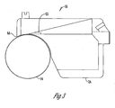
- Figs. 1-3 show a skinning machine 10 that has a frame 12 and a toothroll 14 that is rotated via a power mechanism that includes a power mechanism or motor 16 by drive system 18 using pulley 20. Parallel to the top of the toothroll 14 is cutting blade 22 that is mounted onto shoe 24. The machine also has a foot switch 26 operated by foot pedal 27 that controls the toothroll 14. The material removed by the skinning process on machine 10 is deposited into collection container 28.
- the transmitter 30 establishes a reference point 31. While any type of transmitter 30 may be used, preferred is a transmitter that generates a DC magnetic field that is picked up by at least one receiver/sensor 32. While any type of sensor 32 may be used, preferred is a sensor 32 that will measure the fields generated by transmitter 30 but also the earth's magnetic field to thereby effect an ultimate measure of the position and the orientation of the object to which it is attached. An example of one such sensor is disclosed in U.S. Pat. No. 4,945,305 by Blood . One skilled in the art will also appreciate that other sensors 32 include a barcode, a piece of metal, a radio frequency receiver, an electronic tag, a color or shape or any other suitable sensor device.
- the sensor 32 is attached to an operator in any conventional manner such as by a strap 34, adhesive or the like.
- the sensor 32 is attached to an article of clothing 36, such as a glove, boot, or shirt in any conventional manner.
- the sensor 32 is connected to a tracking device 38 by either an electrical cable or a wireless connection.
- the tracking device 38 has a processor 40 that receives information from the sensors 32.
- a danger zone 42 is programmed into the processor 40.
- the danger zone 42 can be calibrated, for example, by having an operator touch the danger contact point 44. In this manner, the system could be programmed to accommodate operators of different size or variation in the machine.
- the danger zone 42 is manually inputted into the processor.
- the danger zone 42 is determined by the time it would take for the machine to come to a stop when operating at full speed as compared to the time it would take an operator to reach the contact point 44 after entering the danger zone 42.
- one or more warning zones 46 are established within the processor either through calibration, manual input, or calculations based on the size of the danger zone 42.
- the processor 40 receives information from the sensor 32, and based on this information determines the position of the sensor 32. Once the position of the sensor 32 is determined, the processor 40 compares the determined position of the sensor 32, with the known warning 46 and danger 42 zones. If the determined position is within a warning zone 46 a warning signal 48 is provided to the operator.
- the warning signal 48 is of any type including audio, light, vibration, or shock. The intensity of the signal 48 may increase as an operator moves closer to the danger zone 42.
- a signal 51 is sent to an actuator 50 on the machine 10 that slows the operation of the machine based upon entry into a warning zone 46.
- the actuator 50 is of any type connected to the drive system of the machine such as an operating controller, a clutch or other type of friction system, a ratch and claw system, or the like. If the processor 40 determines that the sensor 32 is within the danger zone 42, it will send a deactivating signal 52 to the actuator 50 which in turn stops the operation of the machine prior to the operator engaging the danger contact point 44. In addition, if the processor determines that a sensor 32 is outside of the zone of operation 54, a deactivating signal 52 is sent to the actuator 50 to stop the machine 10.
- a method and means for controlling the operation of a machine based on the wearing of a sensor has been shown that, at the very least, meets all the stated objectives.
Landscapes
- Engineering & Computer Science (AREA)
- General Engineering & Computer Science (AREA)
- Mechanical Engineering (AREA)
- Radar, Positioning & Navigation (AREA)
- Remote Sensing (AREA)
- Life Sciences & Earth Sciences (AREA)
- Food Science & Technology (AREA)
- Emergency Alarm Devices (AREA)
- Professional, Industrial, Or Sporting Protective Garments (AREA)
- Manipulator (AREA)
- Sewing Machines And Sewing (AREA)
Description
- Injuries resulting from the operation of machinery are well known and include injuries to body parts that become caught in machinery. Sometimes, articles of clothing become caught in operating machinery that also leads to injuries.
- Prior art discloses several types of mechanisms that attempt to prevent or minimize the possibility of operators being injured when working with machines. These devices include the use of mechanisms, special mats, shoes, gloves, or other equipment that are cumbersome, expensive, or unreliable. Further, some of these devices are programmed to stop only after an operator makes contact with a danger point. These safety devices give a false sense of security to the operator and can add additional hazards to the machine. Therefore, it is desired to have a device that improves upon these deficiencies in the art.
-
U.S. patent application 2002/0082803 describes a hazardous area warning system with a non-directional magnetic field based proximity receiver for warning personal of an attendant hazard. The receiver includes a x-axis receiver with an antenna directed in a x direction, a y-axis receiver with an antenna directed in a y direction and a z-axis receiver with an antenna directed in a z direction. The antennas may be a wire loop wrapped around a ferrite core. The output from each of the three receivers is combined in an adder. The combined result from the adder is representative of the distance between the receiver and a warning transmitter antenna. The receiver wearer is warned of the attendant hazard, visually and/or tactilly, e.g. with warning lights and/or vibrations. -
U.S. Patent 6,717,514 describes an alarm system. The alarm system is positioned to allow safe operation of machinery while tracking the operator's movement. A transmitter attached to the operator's hand allows monitoring of the operator and prevents unsafe actuation of the machinery. The alarm system includes a trio of X, Y and Z spatially positioned receivers which are connected to a programmed system controller to activate alarms or to terminate power to the machinery. -
EP 1 514 656 describes a power tool that is equipped with a radar for transmitting radio waves towards an area in a vicinity of a rotating tool and for receiving reflected radio waves reflected from a radio wave reflector existing within the area. From the reflected radio waves received by the radar, a distance between the radio wave reflector and the radar, and a speed of change of that distance are calculated. -
US-A-5 939 986 discloses a further system and method of controlling the operation of a machine. - An object of the present invention is to provide a system that ensures that a machine will not operate when an individual enters a danger zone.
- Another object of the present invention is to provide a system that detects when an operator is near a danger zone.
- Another object of the present invention if to provide a system that has a control system that will gradually shut down as an operator nears the danger zone.
- These and other objectives, features, and enhancements will be shown by the following description.
- A method and system for controlling the operation of a machine by an operator having a transmitter mounted to a machine, a sensor attached to an operator or an operator's clothing, and a tracking device that receives signals from the sensor and determines the position of the sensor and compares the determined position of the sensor with a predetermined warning zone and a predetermined danger zone; and the processor is operable to send a deactivating signal to an actuator mounted on the machine when the determined position is within the danger zone, wherein the processor is operable to send a signal to the actuator that slows the operation of the machine when the determined position of the sensor is within the predetermined warning zone. Based on the determined position of the sensor, the tracking device sends signals to the operator and an actuator on the machine based on a comparison with a danger zone, warning zone, or operator zone.
-
-
FIG. 1 is a perspective view of a skinning machine; -
FIG. 2 is a side view of a skinning machine; -
FIG. 3 is a side view of a toothroll, shoe, and blade of a skinning machine; and -
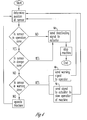
FIG. 4 is a flow chart diagram of a method for controlling the operation of a machine. - The invention may be used with any type of equipment including, but not limited to, meat processing equipment, grain handling equipment, farm implements, conveyors, and manufacturing equipment. For purposes of example only, the invention will be described in relation to a skinning machine for removing the skin and fat from meat products.
-
Figs. 1-3 show askinning machine 10 that has aframe 12 and atoothroll 14 that is rotated via a power mechanism that includes a power mechanism ormotor 16 bydrive system 18 usingpulley 20. Parallel to the top of thetoothroll 14 is cuttingblade 22 that is mounted ontoshoe 24. The machine also has afoot switch 26 operated byfoot pedal 27 that controls thetoothroll 14. The material removed by the skinning process onmachine 10 is deposited intocollection container 28. - Mounted to the
frame 12 is at least onetransmitter 30. Thetransmitter 30 establishes areference point 31. While any type oftransmitter 30 may be used, preferred is a transmitter that generates a DC magnetic field that is picked up by at least one receiver/sensor 32. While any type ofsensor 32 may be used, preferred is asensor 32 that will measure the fields generated bytransmitter 30 but also the earth's magnetic field to thereby effect an ultimate measure of the position and the orientation of the object to which it is attached. An example of one such sensor is disclosed inU.S. Pat. No. 4,945,305 by Blood . One skilled in the art will also appreciate thatother sensors 32 include a barcode, a piece of metal, a radio frequency receiver, an electronic tag, a color or shape or any other suitable sensor device. - The
sensor 32 is attached to an operator in any conventional manner such as by astrap 34, adhesive or the like. Alternatively, thesensor 32 is attached to an article ofclothing 36, such as a glove, boot, or shirt in any conventional manner. Preferred is asensor 32 that is removably attached to an article ofclothing 36 so that theclothing 36 may be laundered orsensors 32 for different machines may be exchanged. - The
sensor 32 is connected to atracking device 38 by either an electrical cable or a wireless connection. Thetracking device 38 has aprocessor 40 that receives information from thesensors 32. Initially, adanger zone 42 is programmed into theprocessor 40. Thedanger zone 42 can be calibrated, for example, by having an operator touch thedanger contact point 44. In this manner, the system could be programmed to accommodate operators of different size or variation in the machine. Alternatively, thedanger zone 42, is manually inputted into the processor. Thedanger zone 42 is determined by the time it would take for the machine to come to a stop when operating at full speed as compared to the time it would take an operator to reach thecontact point 44 after entering thedanger zone 42. In addition, one ormore warning zones 46 are established within the processor either through calibration, manual input, or calculations based on the size of thedanger zone 42. - The
processor 40 receives information from thesensor 32, and based on this information determines the position of thesensor 32. Once the position of thesensor 32 is determined, theprocessor 40 compares the determined position of thesensor 32, with the knownwarning 46 anddanger 42 zones. If the determined position is within a warning zone 46 a warning signal 48 is provided to the operator. The warning signal 48 is of any type including audio, light, vibration, or shock. The intensity of the signal 48 may increase as an operator moves closer to thedanger zone 42. In addition, in one preferred embodiment, asignal 51 is sent to anactuator 50 on themachine 10 that slows the operation of the machine based upon entry into awarning zone 46. Theactuator 50 is of any type connected to the drive system of the machine such as an operating controller, a clutch or other type of friction system, a ratch and claw system, or the like. If theprocessor 40 determines that thesensor 32 is within thedanger zone 42, it will send a deactivatingsignal 52 to theactuator 50 which in turn stops the operation of the machine prior to the operator engaging thedanger contact point 44. In addition, if the processor determines that asensor 32 is outside of the zone of operation 54, a deactivatingsignal 52 is sent to theactuator 50 to stop themachine 10. - A method and means for controlling the operation of a machine based on the wearing of a sensor has been shown that, at the very least, meets all the stated objectives.
Claims (13)
- A system for controlling the operation of a machine (10) by an operator, comprising:- at least one transmitter (30) mounted to the machine (10) that creates a reference point (31);- at least one sensor (32) adapted to be attached to the operator and is connected to a tracking device (38);- the tracking device having a processor (40) that receives a signal from the sensor (32), determines the position of the sensor (32), and compares the determined position of the sensor (32) with a predetermined warning zone (46) and a predetermined danger zone (42); and- the processor (40) is operable to send a deactivating signal (52) to an actuator (50) mounted on the machine (10) and connected to the drive system of the machine (10) when the determined position is within the danger zone (42),characterized in that the processor (40) is operable to send a signal (51) to the actuator (50) that slows the operation of the machine (10) when the determined position of the sensor (32) is within the predetermined warning zone (46).
- The system of claim 1 wherein the processor (40) compares the determined position of the sensor (32) with the predetermined warning zone (46) and is operable to send a warning signal (48) to the operator.
- The system of claim 2 wherein the intensity of the warning signal (48) increases as the determined position of the sensor (32) moves closer to the danger zone (42).
- The system of claim 1 wherein the processor (40) compares the determined position of the sensor (32) with a predetermined zone of operation (54) for the machine (10) and is operable to send a deactivating signal (52) to the actuator (50) when the determined position is outside the zone of operation (54).
- The system of claim 1 wherein at least one sensor (32) is attached to an article of clothing (36) worn by the operator.
- The system of claim 1 wherein the predetermined danger zone (42) is calibrated.
- A method of controlling the operation of a machine (10) by an operator, comprising the steps of:- mounting a transmitter (30) to the machine (10);- attaching a sensor (32) to the operator;- transmitting sensed information from the sensor (32) to a tracking device (38) having a processor (40) that receives the transmitted sensed information;- determining the position of the sensor (32) based on the transmitted information with the processor (40);- comparing the determined position of the sensor with a predetermined warning zone (46) and a predetermined danger zone (42); and- transmitting a deactivating signal (52) from the processor (40) to an actuator (50) mounted on the machine (10) and connected to the drive system of the machine (10) when the determined position is within the predetermined danger zone (42),characterized in that the method further comprises the step of transmitting a signal (51) to the actuator (50) that slows the operation of the machine (10) when the determined position of the sensor (32) is within the predetermined warning zone (46).
- The method of claim 7 further comprising the step of calibrating the danger zone (42).
- The method of claim 7 further comprising the step of comparing the determined position of the sensor (32) with the predetermined warning zone (46) and sending a warning signal (48) to the operator.
- The method of claim 9 wherein the intensity of the warning signal (48) increases as the determined position of the sensor (32) moves closer to the danger zone (42).
- The method of claim 7 further comprising the step of sending a deactivating signal (52) to the actuator (50) when the determined position of the sensor (32) is outside a zone of operation (54).
- The method of claim 7 wherein the sensor (32) is attached to an article of clothing (36) worn by the operator.
- The system of claim 1 wherein the machine (10) is a meat skinner.
Applications Claiming Priority (2)
| Application Number | Priority Date | Filing Date | Title |
|---|---|---|---|
| US11/538,177 US7663492B2 (en) | 2006-10-03 | 2006-10-03 | Method and means for controlling the operation of a machine based upon the wearing of a sensor by a machine operator |
| PCT/US2007/080058 WO2008042838A2 (en) | 2006-10-03 | 2007-10-01 | Method and means for controlling the operation of a machine based upon the wearing of a sensor by a machine operator |
Publications (2)
| Publication Number | Publication Date |
|---|---|
| EP2066960A2 EP2066960A2 (en) | 2009-06-10 |
| EP2066960B1 true EP2066960B1 (en) | 2016-01-06 |
Family
ID=39156297
Family Applications (1)
| Application Number | Title | Priority Date | Filing Date |
|---|---|---|---|
| EP07843595.5A Not-in-force EP2066960B1 (en) | 2006-10-03 | 2007-10-01 | Method and means for controlling the operation of a machine based upon the wearing of a sensor by a machine operator |
Country Status (6)
| Country | Link |
|---|---|
| US (1) | US7663492B2 (en) |
| EP (1) | EP2066960B1 (en) |
| BR (1) | BRPI0719968A2 (en) |
| CA (1) | CA2665327A1 (en) |
| DK (1) | DK2066960T3 (en) |
| WO (1) | WO2008042838A2 (en) |
Families Citing this family (12)
| Publication number | Priority date | Publication date | Assignee | Title |
|---|---|---|---|---|
| US20080115541A1 (en) * | 2006-11-22 | 2008-05-22 | Aldridge Jeffrey L | Garment Processing Personnel Safety Apparatus |
| US7876220B2 (en) * | 2006-11-22 | 2011-01-25 | Cintas Corporation | Garment tracking and processing system |
| US20080116274A1 (en) * | 2006-11-22 | 2008-05-22 | Aldridge Jeffrey L | Garment RFID Private Protocol Apparatus |
| DE102007032221A1 (en) * | 2007-07-11 | 2009-01-15 | Robert Bosch Gmbh | Machine tool and method with a machine tool |
| DE102008063081B4 (en) * | 2008-12-24 | 2014-10-23 | Gottfried Wilhelm Leibniz Universität Hannover | Securing device and method for operating a multi-unit machine |
| EP2286970A1 (en) * | 2009-08-18 | 2011-02-23 | Robert Bosch GmbH | Power tool and method for providing user feedback |
| US9682826B2 (en) * | 2013-06-23 | 2017-06-20 | Top Tier, Llc | Item infeed apparatus and method for a palletizer system |
| WO2015140770A2 (en) * | 2014-03-20 | 2015-09-24 | Steelpro- Engenharia Industrial Lda | Wearable safety device and system for sawing, cutting and milling machines |
| US20180211345A1 (en) * | 2015-07-20 | 2018-07-26 | 802179 Alberta Ltd | Automated system and process for providing personal safety |
| WO2017165757A1 (en) * | 2016-03-24 | 2017-09-28 | Warwick Mills, Inc. | Wearable safety warning and measurement system |
| US20190234559A1 (en) * | 2018-01-31 | 2019-08-01 | Hollymatic Corporation | Method and system to monitor and shut down saw |
| US12279623B2 (en) * | 2019-11-06 | 2025-04-22 | Kando Innovation Limited | Productivity enhancement apparatus for power operated skinning equipment |
Citations (3)
| Publication number | Priority date | Publication date | Assignee | Title |
|---|---|---|---|---|
| US5939986A (en) * | 1996-10-18 | 1999-08-17 | The United States Of America As Represented By The United States Department Of Energy | Mobile machine hazardous working zone warning system |
| US6717514B1 (en) * | 2002-07-17 | 2004-04-06 | Richard M. Stein | Alarm system and method |
| EP1514656A1 (en) * | 2003-09-12 | 2005-03-16 | Makita Corporation | Power tool |
Family Cites Families (13)
| Publication number | Priority date | Publication date | Assignee | Title |
|---|---|---|---|---|
| US3953770A (en) * | 1974-07-11 | 1976-04-27 | Jinnosuke Hayashi | Safety equipment for machinery used in processing plates, etc. |
| DK215385D0 (en) | 1985-05-15 | 1985-05-15 | Northern Food Line Machines K | SAFETY SYSTEM FOR USE IN WORKING MACHINES |
| US4945305A (en) | 1986-10-09 | 1990-07-31 | Ascension Technology Corporation | Device for quantitatively measuring the relative position and orientation of two bodies in the presence of metals utilizing direct current magnetic fields |
| US5563581A (en) | 1995-07-05 | 1996-10-08 | Kats; Vyacheslay | Safety device for machine tool operators, and the like |
| DE19829019A1 (en) | 1998-06-30 | 2000-01-05 | Poettinger Gmbh Geb | Cutting machine, especially for reducing branches or pieces of wood in size, with safety device reducing risk of damage by embedded metal objects |
| US6853531B2 (en) * | 1998-12-02 | 2005-02-08 | Corey Alexander Mather | Material processing machine |
| US7365955B2 (en) * | 1998-12-02 | 2008-04-29 | Corey Alexander Mather | Material processing machine |
| AUPP743998A0 (en) * | 1998-12-02 | 1998-12-24 | Gust, Mark William | Wood chipper safety system |
| US6810353B2 (en) | 2000-10-26 | 2004-10-26 | The United States Of America As Represented By The Secretary Of The Department Of Health And Human Services, Centers For Disease Control | Non-directional magnet field based proximity receiver with multiple warning and machine shutdown capability |
| US20020111702A1 (en) | 2001-02-15 | 2002-08-15 | Angel Jeffrey R. | Factory personnel monitors |
| US6672860B2 (en) * | 2002-04-10 | 2004-01-06 | Hon Technology Inc. | Proximity warning system for a fireplace |
| US6856852B1 (en) | 2003-10-17 | 2005-02-15 | Townsend Engineering Company | Method and means for controlling the operation of a machine based upon the wearing apparel by the machine operator |
| US7696751B2 (en) * | 2005-12-08 | 2010-04-13 | Koninklijke Philips Electronics N. V. | Method and apparatus for ferrous object and/or magnetic field detection for MRI safety |
-
2006
- 2006-10-03 US US11/538,177 patent/US7663492B2/en active Active
-
2007
- 2007-10-01 DK DK07843595.5T patent/DK2066960T3/en active
- 2007-10-01 BR BRPI0719968-6A patent/BRPI0719968A2/en not_active IP Right Cessation
- 2007-10-01 EP EP07843595.5A patent/EP2066960B1/en not_active Not-in-force
- 2007-10-01 WO PCT/US2007/080058 patent/WO2008042838A2/en not_active Ceased
- 2007-10-01 CA CA002665327A patent/CA2665327A1/en not_active Abandoned
Patent Citations (3)
| Publication number | Priority date | Publication date | Assignee | Title |
|---|---|---|---|---|
| US5939986A (en) * | 1996-10-18 | 1999-08-17 | The United States Of America As Represented By The United States Department Of Energy | Mobile machine hazardous working zone warning system |
| US6717514B1 (en) * | 2002-07-17 | 2004-04-06 | Richard M. Stein | Alarm system and method |
| EP1514656A1 (en) * | 2003-09-12 | 2005-03-16 | Makita Corporation | Power tool |
Also Published As
| Publication number | Publication date |
|---|---|
| DK2066960T3 (en) | 2016-04-11 |
| US20080079590A1 (en) | 2008-04-03 |
| EP2066960A2 (en) | 2009-06-10 |
| WO2008042838A2 (en) | 2008-04-10 |
| US7663492B2 (en) | 2010-02-16 |
| CA2665327A1 (en) | 2008-04-10 |
| BRPI0719968A2 (en) | 2014-02-11 |
| WO2008042838A3 (en) | 2008-05-22 |
Similar Documents
| Publication | Publication Date | Title |
|---|---|---|
| DK2066960T3 (en) | PROCEDURE AND MEASURES TO CONTROL THE OPERATION OF A MACHINE BASED ON A MACHINE OPERATOR'S CARRYING A SENSOR | |
| US6979813B2 (en) | Safety-shutoff device for a manually fed processing machine | |
| CN100396990C (en) | Device for contact protection and protection method against contact with moving parts | |
| US5942975A (en) | Method and a device for sensing the distance between a first object and a second object | |
| EP4139075B1 (en) | System for protecting an operator of a power tool | |
| EP2984641B1 (en) | System and method for position detection | |
| GB2473091A (en) | Safety Arrangement for Plug or Socket | |
| WO2015140770A2 (en) | Wearable safety device and system for sawing, cutting and milling machines | |
| WO2011002478A4 (en) | Apparatus for remotely controlling a materials handling vehicle | |
| US6856852B1 (en) | Method and means for controlling the operation of a machine based upon the wearing apparel by the machine operator | |
| CN114340849B (en) | Machine tool device | |
| KR20120128081A (en) | A wearable rfid system | |
| US7365955B2 (en) | Material processing machine | |
| US10514672B1 (en) | Machinery accident prevention system | |
| ITMI20091157A1 (en) | LAWNMOWER | |
| US10663113B2 (en) | Safety system and method for a portable electrical tool | |
| US20210048145A1 (en) | Safety System For Machinery | |
| US20020171993A1 (en) | Material processing machine | |
| WO1996037350A1 (en) | Improvements in safety equipment for motor driven saws | |
| JPH0728650B2 (en) | Safety device and method for meat peeler | |
| JP2006313425A (en) | Safety belt device for work | |
| GB2473860A (en) | Accident mitigation system | |
| AU2004231160B2 (en) | A material processing machine | |
| JP2000271797A (en) | Electromagnetic wave detecting type safety monitoring device | |
| US5160289A (en) | Safety means for powered machinery |
Legal Events
| Date | Code | Title | Description |
|---|---|---|---|
| PUAI | Public reference made under article 153(3) epc to a published international application that has entered the european phase |
Free format text: ORIGINAL CODE: 0009012 |
|
| 17P | Request for examination filed |
Effective date: 20090408 |
|
| AK | Designated contracting states |
Kind code of ref document: A2 Designated state(s): AT BE BG CH CY CZ DE DK EE ES FI FR GB GR HU IE IS IT LI LT LU LV MC MT NL PL PT RO SE SI SK TR |
|
| AX | Request for extension of the european patent |
Extension state: AL BA HR MK RS |
|
| DAX | Request for extension of the european patent (deleted) | ||
| 17Q | First examination report despatched |
Effective date: 20120618 |
|
| GRAP | Despatch of communication of intention to grant a patent |
Free format text: ORIGINAL CODE: EPIDOSNIGR1 |
|
| INTG | Intention to grant announced |
Effective date: 20150720 |
|
| GRAS | Grant fee paid |
Free format text: ORIGINAL CODE: EPIDOSNIGR3 |
|
| GRAA | (expected) grant |
Free format text: ORIGINAL CODE: 0009210 |
|
| AK | Designated contracting states |
Kind code of ref document: B1 Designated state(s): AT BE BG CH CY CZ DE DK EE ES FI FR GB GR HU IE IS IT LI LT LU LV MC MT NL PL PT RO SE SI SK TR |
|
| REG | Reference to a national code |
Ref country code: GB Ref legal event code: FG4D |
|
| REG | Reference to a national code |
Ref country code: CH Ref legal event code: EP |
|
| REG | Reference to a national code |
Ref country code: IE Ref legal event code: FG4D |
|
| REG | Reference to a national code |
Ref country code: AT Ref legal event code: REF Ref document number: 769150 Country of ref document: AT Kind code of ref document: T Effective date: 20160215 |
|
| REG | Reference to a national code |
Ref country code: DE Ref legal event code: R096 Ref document number: 602007044498 Country of ref document: DE |
|
| REG | Reference to a national code |
Ref country code: DK Ref legal event code: T3 Effective date: 20160408 |
|
| REG | Reference to a national code |
Ref country code: NL Ref legal event code: FP |
|
| REG | Reference to a national code |
Ref country code: LT Ref legal event code: MG4D |
|
| REG | Reference to a national code |
Ref country code: AT Ref legal event code: MK05 Ref document number: 769150 Country of ref document: AT Kind code of ref document: T Effective date: 20160106 |
|
| PG25 | Lapsed in a contracting state [announced via postgrant information from national office to epo] |
Ref country code: ES Free format text: LAPSE BECAUSE OF FAILURE TO SUBMIT A TRANSLATION OF THE DESCRIPTION OR TO PAY THE FEE WITHIN THE PRESCRIBED TIME-LIMIT Effective date: 20160106 Ref country code: FI Free format text: LAPSE BECAUSE OF FAILURE TO SUBMIT A TRANSLATION OF THE DESCRIPTION OR TO PAY THE FEE WITHIN THE PRESCRIBED TIME-LIMIT Effective date: 20160106 Ref country code: GR Free format text: LAPSE BECAUSE OF FAILURE TO SUBMIT A TRANSLATION OF THE DESCRIPTION OR TO PAY THE FEE WITHIN THE PRESCRIBED TIME-LIMIT Effective date: 20160407 |
|
| PG25 | Lapsed in a contracting state [announced via postgrant information from national office to epo] |
Ref country code: AT Free format text: LAPSE BECAUSE OF FAILURE TO SUBMIT A TRANSLATION OF THE DESCRIPTION OR TO PAY THE FEE WITHIN THE PRESCRIBED TIME-LIMIT Effective date: 20160106 Ref country code: PL Free format text: LAPSE BECAUSE OF FAILURE TO SUBMIT A TRANSLATION OF THE DESCRIPTION OR TO PAY THE FEE WITHIN THE PRESCRIBED TIME-LIMIT Effective date: 20160106 Ref country code: SE Free format text: LAPSE BECAUSE OF FAILURE TO SUBMIT A TRANSLATION OF THE DESCRIPTION OR TO PAY THE FEE WITHIN THE PRESCRIBED TIME-LIMIT Effective date: 20160106 Ref country code: IS Free format text: LAPSE BECAUSE OF FAILURE TO SUBMIT A TRANSLATION OF THE DESCRIPTION OR TO PAY THE FEE WITHIN THE PRESCRIBED TIME-LIMIT Effective date: 20160506 Ref country code: LT Free format text: LAPSE BECAUSE OF FAILURE TO SUBMIT A TRANSLATION OF THE DESCRIPTION OR TO PAY THE FEE WITHIN THE PRESCRIBED TIME-LIMIT Effective date: 20160106 Ref country code: LV Free format text: LAPSE BECAUSE OF FAILURE TO SUBMIT A TRANSLATION OF THE DESCRIPTION OR TO PAY THE FEE WITHIN THE PRESCRIBED TIME-LIMIT Effective date: 20160106 Ref country code: PT Free format text: LAPSE BECAUSE OF FAILURE TO SUBMIT A TRANSLATION OF THE DESCRIPTION OR TO PAY THE FEE WITHIN THE PRESCRIBED TIME-LIMIT Effective date: 20160506 |
|
| REG | Reference to a national code |
Ref country code: FR Ref legal event code: PLFP Year of fee payment: 10 |
|
| REG | Reference to a national code |
Ref country code: DE Ref legal event code: R097 Ref document number: 602007044498 Country of ref document: DE |
|
| PG25 | Lapsed in a contracting state [announced via postgrant information from national office to epo] |
Ref country code: EE Free format text: LAPSE BECAUSE OF FAILURE TO SUBMIT A TRANSLATION OF THE DESCRIPTION OR TO PAY THE FEE WITHIN THE PRESCRIBED TIME-LIMIT Effective date: 20160106 |
|
| PLBE | No opposition filed within time limit |
Free format text: ORIGINAL CODE: 0009261 |
|
| STAA | Information on the status of an ep patent application or granted ep patent |
Free format text: STATUS: NO OPPOSITION FILED WITHIN TIME LIMIT |
|
| PG25 | Lapsed in a contracting state [announced via postgrant information from national office to epo] |
Ref country code: RO Free format text: LAPSE BECAUSE OF FAILURE TO SUBMIT A TRANSLATION OF THE DESCRIPTION OR TO PAY THE FEE WITHIN THE PRESCRIBED TIME-LIMIT Effective date: 20160106 Ref country code: SK Free format text: LAPSE BECAUSE OF FAILURE TO SUBMIT A TRANSLATION OF THE DESCRIPTION OR TO PAY THE FEE WITHIN THE PRESCRIBED TIME-LIMIT Effective date: 20160106 Ref country code: CZ Free format text: LAPSE BECAUSE OF FAILURE TO SUBMIT A TRANSLATION OF THE DESCRIPTION OR TO PAY THE FEE WITHIN THE PRESCRIBED TIME-LIMIT Effective date: 20160106 |
|
| 26N | No opposition filed |
Effective date: 20161007 |
|
| PG25 | Lapsed in a contracting state [announced via postgrant information from national office to epo] |
Ref country code: BG Free format text: LAPSE BECAUSE OF FAILURE TO SUBMIT A TRANSLATION OF THE DESCRIPTION OR TO PAY THE FEE WITHIN THE PRESCRIBED TIME-LIMIT Effective date: 20160406 Ref country code: SI Free format text: LAPSE BECAUSE OF FAILURE TO SUBMIT A TRANSLATION OF THE DESCRIPTION OR TO PAY THE FEE WITHIN THE PRESCRIBED TIME-LIMIT Effective date: 20160106 |
|
| REG | Reference to a national code |
Ref country code: CH Ref legal event code: PL |
|
| REG | Reference to a national code |
Ref country code: IE Ref legal event code: MM4A |
|
| PG25 | Lapsed in a contracting state [announced via postgrant information from national office to epo] |
Ref country code: CH Free format text: LAPSE BECAUSE OF NON-PAYMENT OF DUE FEES Effective date: 20161031 Ref country code: LI Free format text: LAPSE BECAUSE OF NON-PAYMENT OF DUE FEES Effective date: 20161031 |
|
| PG25 | Lapsed in a contracting state [announced via postgrant information from national office to epo] |
Ref country code: LU Free format text: LAPSE BECAUSE OF NON-PAYMENT OF DUE FEES Effective date: 20161001 |
|
| REG | Reference to a national code |
Ref country code: FR Ref legal event code: PLFP Year of fee payment: 11 |
|
| PG25 | Lapsed in a contracting state [announced via postgrant information from national office to epo] |
Ref country code: IE Free format text: LAPSE BECAUSE OF NON-PAYMENT OF DUE FEES Effective date: 20161001 |
|
| PG25 | Lapsed in a contracting state [announced via postgrant information from national office to epo] |
Ref country code: HU Free format text: LAPSE BECAUSE OF FAILURE TO SUBMIT A TRANSLATION OF THE DESCRIPTION OR TO PAY THE FEE WITHIN THE PRESCRIBED TIME-LIMIT; INVALID AB INITIO Effective date: 20071001 Ref country code: CY Free format text: LAPSE BECAUSE OF FAILURE TO SUBMIT A TRANSLATION OF THE DESCRIPTION OR TO PAY THE FEE WITHIN THE PRESCRIBED TIME-LIMIT Effective date: 20160106 |
|
| PG25 | Lapsed in a contracting state [announced via postgrant information from national office to epo] |
Ref country code: MT Free format text: LAPSE BECAUSE OF NON-PAYMENT OF DUE FEES Effective date: 20161031 Ref country code: MC Free format text: LAPSE BECAUSE OF FAILURE TO SUBMIT A TRANSLATION OF THE DESCRIPTION OR TO PAY THE FEE WITHIN THE PRESCRIBED TIME-LIMIT Effective date: 20160106 Ref country code: TR Free format text: LAPSE BECAUSE OF FAILURE TO SUBMIT A TRANSLATION OF THE DESCRIPTION OR TO PAY THE FEE WITHIN THE PRESCRIBED TIME-LIMIT Effective date: 20160106 |
|
| REG | Reference to a national code |
Ref country code: FR Ref legal event code: PLFP Year of fee payment: 12 |
|
| PGFP | Annual fee paid to national office [announced via postgrant information from national office to epo] |
Ref country code: NL Payment date: 20191026 Year of fee payment: 13 |
|
| PGFP | Annual fee paid to national office [announced via postgrant information from national office to epo] |
Ref country code: DK Payment date: 20191029 Year of fee payment: 13 Ref country code: FR Payment date: 20191025 Year of fee payment: 13 |
|
| PGFP | Annual fee paid to national office [announced via postgrant information from national office to epo] |
Ref country code: GB Payment date: 20191028 Year of fee payment: 13 |
|
| REG | Reference to a national code |
Ref country code: DK Ref legal event code: EBP Effective date: 20201031 |
|
| REG | Reference to a national code |
Ref country code: NL Ref legal event code: MM Effective date: 20201101 |
|
| GBPC | Gb: european patent ceased through non-payment of renewal fee |
Effective date: 20201001 |
|
| PG25 | Lapsed in a contracting state [announced via postgrant information from national office to epo] |
Ref country code: NL Free format text: LAPSE BECAUSE OF NON-PAYMENT OF DUE FEES Effective date: 20201101 Ref country code: FR Free format text: LAPSE BECAUSE OF NON-PAYMENT OF DUE FEES Effective date: 20201031 |
|
| PG25 | Lapsed in a contracting state [announced via postgrant information from national office to epo] |
Ref country code: GB Free format text: LAPSE BECAUSE OF NON-PAYMENT OF DUE FEES Effective date: 20201001 |
|
| PG25 | Lapsed in a contracting state [announced via postgrant information from national office to epo] |
Ref country code: DK Free format text: LAPSE BECAUSE OF NON-PAYMENT OF DUE FEES Effective date: 20201031 |
|
| P01 | Opt-out of the competence of the unified patent court (upc) registered |
Effective date: 20230514 |
|
| REG | Reference to a national code |
Ref country code: DE Ref legal event code: R082 Ref document number: 602007044498 Country of ref document: DE Representative=s name: MAIWALD GMBH, DE |
|
| PGFP | Annual fee paid to national office [announced via postgrant information from national office to epo] |
Ref country code: IT Payment date: 20230920 Year of fee payment: 17 |
|
| PGFP | Annual fee paid to national office [announced via postgrant information from national office to epo] |
Ref country code: BE Payment date: 20230920 Year of fee payment: 17 |
|
| PGFP | Annual fee paid to national office [announced via postgrant information from national office to epo] |
Ref country code: DE Payment date: 20230920 Year of fee payment: 17 |
|
| REG | Reference to a national code |
Ref country code: DE Ref legal event code: R119 Ref document number: 602007044498 Country of ref document: DE |
|
| PG25 | Lapsed in a contracting state [announced via postgrant information from national office to epo] |
Ref country code: DE Free format text: LAPSE BECAUSE OF NON-PAYMENT OF DUE FEES Effective date: 20250501 |
|
| PG25 | Lapsed in a contracting state [announced via postgrant information from national office to epo] |
Ref country code: BE Free format text: LAPSE BECAUSE OF NON-PAYMENT OF DUE FEES Effective date: 20241031 |
|
| REG | Reference to a national code |
Ref country code: BE Ref legal event code: MM Effective date: 20241031 |
|
| PG25 | Lapsed in a contracting state [announced via postgrant information from national office to epo] |
Ref country code: IT Free format text: LAPSE BECAUSE OF NON-PAYMENT OF DUE FEES Effective date: 20241001 |