EP2066879B1 - Gas treatment device - Google Patents
Gas treatment device Download PDFInfo
- Publication number
- EP2066879B1 EP2066879B1 EP07804509A EP07804509A EP2066879B1 EP 2066879 B1 EP2066879 B1 EP 2066879B1 EP 07804509 A EP07804509 A EP 07804509A EP 07804509 A EP07804509 A EP 07804509A EP 2066879 B1 EP2066879 B1 EP 2066879B1
- Authority
- EP
- European Patent Office
- Prior art keywords
- chamber
- foam
- shell
- segments
- metal foam
- Prior art date
- Legal status (The legal status is an assumption and is not a legal conclusion. Google has not performed a legal analysis and makes no representation as to the accuracy of the status listed.)
- Not-in-force
Links
Images
Classifications
-
- F—MECHANICAL ENGINEERING; LIGHTING; HEATING; WEAPONS; BLASTING
- F01—MACHINES OR ENGINES IN GENERAL; ENGINE PLANTS IN GENERAL; STEAM ENGINES
- F01N—GAS-FLOW SILENCERS OR EXHAUST APPARATUS FOR MACHINES OR ENGINES IN GENERAL; GAS-FLOW SILENCERS OR EXHAUST APPARATUS FOR INTERNAL-COMBUSTION ENGINES
- F01N3/00—Exhaust or silencing apparatus having means for purifying, rendering innocuous, or otherwise treating exhaust
- F01N3/08—Exhaust or silencing apparatus having means for purifying, rendering innocuous, or otherwise treating exhaust for rendering innocuous
- F01N3/10—Exhaust or silencing apparatus having means for purifying, rendering innocuous, or otherwise treating exhaust for rendering innocuous by thermal or catalytic conversion of noxious components of exhaust
- F01N3/24—Exhaust or silencing apparatus having means for purifying, rendering innocuous, or otherwise treating exhaust for rendering innocuous by thermal or catalytic conversion of noxious components of exhaust characterised by constructional aspects of converting apparatus
- F01N3/28—Construction of catalytic reactors
-
- B—PERFORMING OPERATIONS; TRANSPORTING
- B01—PHYSICAL OR CHEMICAL PROCESSES OR APPARATUS IN GENERAL
- B01D—SEPARATION
- B01D46/00—Filters or filtering processes specially modified for separating dispersed particles from gases or vapours
- B01D46/24—Particle separators, e.g. dust precipitators, using rigid hollow filter bodies
- B01D46/2403—Particle separators, e.g. dust precipitators, using rigid hollow filter bodies characterised by the physical shape or structure of the filtering element
-
- B—PERFORMING OPERATIONS; TRANSPORTING
- B01—PHYSICAL OR CHEMICAL PROCESSES OR APPARATUS IN GENERAL
- B01D—SEPARATION
- B01D53/00—Separation of gases or vapours; Recovering vapours of volatile solvents from gases; Chemical or biological purification of waste gases, e.g. engine exhaust gases, smoke, fumes, flue gases, aerosols
- B01D53/34—Chemical or biological purification of waste gases
- B01D53/92—Chemical or biological purification of waste gases of engine exhaust gases
- B01D53/94—Chemical or biological purification of waste gases of engine exhaust gases by catalytic processes
-
- B—PERFORMING OPERATIONS; TRANSPORTING
- B01—PHYSICAL OR CHEMICAL PROCESSES OR APPARATUS IN GENERAL
- B01D—SEPARATION
- B01D53/00—Separation of gases or vapours; Recovering vapours of volatile solvents from gases; Chemical or biological purification of waste gases, e.g. engine exhaust gases, smoke, fumes, flue gases, aerosols
- B01D53/34—Chemical or biological purification of waste gases
- B01D53/92—Chemical or biological purification of waste gases of engine exhaust gases
- B01D53/94—Chemical or biological purification of waste gases of engine exhaust gases by catalytic processes
- B01D53/9445—Simultaneously removing carbon monoxide, hydrocarbons or nitrogen oxides making use of three-way catalysts [TWC] or four-way-catalysts [FWC]
- B01D53/9454—Simultaneously removing carbon monoxide, hydrocarbons or nitrogen oxides making use of three-way catalysts [TWC] or four-way-catalysts [FWC] characterised by a specific device
-
- F—MECHANICAL ENGINEERING; LIGHTING; HEATING; WEAPONS; BLASTING
- F01—MACHINES OR ENGINES IN GENERAL; ENGINE PLANTS IN GENERAL; STEAM ENGINES
- F01N—GAS-FLOW SILENCERS OR EXHAUST APPARATUS FOR MACHINES OR ENGINES IN GENERAL; GAS-FLOW SILENCERS OR EXHAUST APPARATUS FOR INTERNAL-COMBUSTION ENGINES
- F01N13/00—Exhaust or silencing apparatus characterised by constructional features
- F01N13/009—Exhaust or silencing apparatus characterised by constructional features having two or more separate purifying devices arranged in series
- F01N13/0097—Exhaust or silencing apparatus characterised by constructional features having two or more separate purifying devices arranged in series the purifying devices are arranged in a single housing
-
- F—MECHANICAL ENGINEERING; LIGHTING; HEATING; WEAPONS; BLASTING
- F01—MACHINES OR ENGINES IN GENERAL; ENGINE PLANTS IN GENERAL; STEAM ENGINES
- F01N—GAS-FLOW SILENCERS OR EXHAUST APPARATUS FOR MACHINES OR ENGINES IN GENERAL; GAS-FLOW SILENCERS OR EXHAUST APPARATUS FOR INTERNAL-COMBUSTION ENGINES
- F01N3/00—Exhaust or silencing apparatus having means for purifying, rendering innocuous, or otherwise treating exhaust
- F01N3/02—Exhaust or silencing apparatus having means for purifying, rendering innocuous, or otherwise treating exhaust for cooling, or for removing solid constituents of, exhaust
- F01N3/021—Exhaust or silencing apparatus having means for purifying, rendering innocuous, or otherwise treating exhaust for cooling, or for removing solid constituents of, exhaust by means of filters
- F01N3/022—Exhaust or silencing apparatus having means for purifying, rendering innocuous, or otherwise treating exhaust for cooling, or for removing solid constituents of, exhaust by means of filters characterised by specially adapted filtering structure, e.g. honeycomb, mesh or fibrous
-
- F—MECHANICAL ENGINEERING; LIGHTING; HEATING; WEAPONS; BLASTING
- F01—MACHINES OR ENGINES IN GENERAL; ENGINE PLANTS IN GENERAL; STEAM ENGINES
- F01N—GAS-FLOW SILENCERS OR EXHAUST APPARATUS FOR MACHINES OR ENGINES IN GENERAL; GAS-FLOW SILENCERS OR EXHAUST APPARATUS FOR INTERNAL-COMBUSTION ENGINES
- F01N3/00—Exhaust or silencing apparatus having means for purifying, rendering innocuous, or otherwise treating exhaust
- F01N3/08—Exhaust or silencing apparatus having means for purifying, rendering innocuous, or otherwise treating exhaust for rendering innocuous
- F01N3/10—Exhaust or silencing apparatus having means for purifying, rendering innocuous, or otherwise treating exhaust for rendering innocuous by thermal or catalytic conversion of noxious components of exhaust
- F01N3/24—Exhaust or silencing apparatus having means for purifying, rendering innocuous, or otherwise treating exhaust for rendering innocuous by thermal or catalytic conversion of noxious components of exhaust characterised by constructional aspects of converting apparatus
- F01N3/28—Construction of catalytic reactors
- F01N3/2892—Exhaust flow directors or the like, e.g. upstream of catalytic device
-
- Y—GENERAL TAGGING OF NEW TECHNOLOGICAL DEVELOPMENTS; GENERAL TAGGING OF CROSS-SECTIONAL TECHNOLOGIES SPANNING OVER SEVERAL SECTIONS OF THE IPC; TECHNICAL SUBJECTS COVERED BY FORMER USPC CROSS-REFERENCE ART COLLECTIONS [XRACs] AND DIGESTS
- Y02—TECHNOLOGIES OR APPLICATIONS FOR MITIGATION OR ADAPTATION AGAINST CLIMATE CHANGE
- Y02T—CLIMATE CHANGE MITIGATION TECHNOLOGIES RELATED TO TRANSPORTATION
- Y02T10/00—Road transport of goods or passengers
- Y02T10/10—Internal combustion engine [ICE] based vehicles
- Y02T10/12—Improving ICE efficiencies
Definitions
- the present invention relates to devices for gas treatment based on metal foams, in particular an exhaust gas after-treatment device, comprising a metal shell defining a cavity with an intake pipe and an outlet pipe and two foam segments made of layered metal foam sheets set in the path of communication between said intake pipe and outlet pipe.
- the metal foam material considered and the manufacturing process are described in the international patent applications WO 2004089564 and WO 2005037467 respectively. According to this process, the metal foam is produced in sheets with the desired length and width.
- Foam based filters to be used or contained in said devices are known for diesel particulate filtering applications, although most of them are based on ceramic materials. Typically ceramic foams with sufficiently small pore sizes to achieve good filtration efficiencies exhibit a relatively high pressure drop, due to the large number of closed pores. Moreover, as more soot is accumulated in the filter, such foams are known to lower their filtration efficiency until a "blow-off" behavior, i.e. a negative efficiency, is observed.
- WO 94/12777 of Flaekt yet discloses an apparatus for reducing the concentrations of unhealthy and polluting elements in exhaust gases from diesel engines. It discloses an inlet chamber (23), an outer chamber (24) and an exit chamber (28), and the flow going through in this order . It discloses a diaphragm (26) and catalytic coating. This document again discloses similar solutions as in the case above, with similar drawbacks however.
- porous metal In the known prior art, the material proposed is generally referred to as porous metal, without specifically detailing the production process.
- some known embodiments are defined by the need to support the thermal regeneration of the filters via the usage of electrical heaters. Therefore the usage of at least two cylindrical filter elements is called for. Due to the limitations related with the material, the production process of the filter elements and of the need of multiple filter elements, the thickness of the filter elements is restricted in the region 0,5 to 20 mm, preferably 1 mm or more.
- a still further known prior art relates to the use of ceramic foams resulting in that they do not provide a solution to solve the aforementioned drawbacks.
- US 4 175 107 of Fukada yet discloses a catalytic converter for purifying the exhaust gases from an internal combustion engine. It discloses inlet, outer and exit chambers, but the flow can go any way, and it further discloses catalytic elements .
- EP 1344907 A1 discloses a device consisting of a body with open cell or open pores structure, for example made of metal foam or metal pot scourer with open pores with a porosity comprised between 20 and 100 pores per Inch, which is determined by the amount of pores along a line.
- the porosity may have different values, but one single value at the time for a certain device. In addition, it tends to solve a problem of providing a device oxidizing soot at lowest possible temperature that is equipped against blocking .
- the purpose of the present invention is to remedy the aforementioned drawbacks and the application field of the present invention is targeted mainly in the area of catalytic substrates for gasoline and diesel engine exhaust after treatment.
- an exhaust gas after-treatment device further comprising two secondary foam segments made of layered metal foam sheets set in the path of communication between said intake pipe and outlet pipe, in addition to the main said two foam segments.
- Said device is remarkable in that said two secondary foam segments also comprise a plurality of layers of metal foam sheets, which are set about the longitudinal axis of the shell in such a way as to define, inside the shell, an inner chamber, an outer chamber, an exit chamber, and a closed chamber, wherein said chambers communicate with said intake, resp. outlet pipes in such a way that during use, the flow of the engine exhaust gases is forced from the inner chamber via the outer chamber and the closed chamber to the exit chamber, thus assuming radial components of velocity with respect to the longitudinal axis of the shell.
- said foam segments of said device are composed of concentric layers of metal foam sheets.
- the foam segments are rolled around perforated tubes.
- the respective diameters of said perforated tubes are different.
- the perforation of the perforated tubes is locally variable.
- the metal foam layers are coated with catalytically active material.
- the catalytic loading of the metal foam layers is variable in any direction.
- said diaphragm has a disc shape with its external diameter assuming any value larger than the diameter of the perforated tubes and lower than the diameter of the outer shell.
- said diaphragm is perforated.
- said perforation of diaphragm is locally variable.
- said perforated tube is closed at its one end by a disc-shaped diaphragm and at its opposite end by a disc-shaped diaphragm, thus forcing the flow of gas entering the inner chamber to pass via the outer chamber and the closed chamber to the exit chamber, which communicates with the outlet pipe.
- each foam sheet is made of a metal alloy, with suitable mechanical properties to allow forming in tubular design.
- the present invention also relates to an engine exhaust after-treatment system comprising a plurality of combinations, each including a device as set out above in serial arrangements.
- the present invention relates to an engine exhaust after-treatment system comprising a plurality of combinations, each including a device as set out above in parallel arrangements.
- the present invention relates to an engine exhaust after-treatment system comprising a plurality of combinations, each including a device as set out above in both serial, resp. parallel arrangements.
- the system according to the present invention further comprises a conduit having a cavity defined by an inner surface and wherein each combination is received in the cavity.
- the metal foam offers a high specific surface area for application of catalytic coatings.
- the foam structure enhances the gas mixing and mass transfer rates between the gas and the catalytic surface.
- An additional property of the metal foam as catalyst substrate is its potential to filter particulate matter from the exhaust gas, which is important in the case of diesel and direct injection gasoline engines. Due to the above properties, the metal foam presents advantages compared to the widely used honeycomb substrates.
- the flow resistance of metal foams depends strongly on their internal structure. To obtain acceptable pressure drop with a foam substrate, it is necessary to optimize both the microstructure - e.g. pore size - and the macro-structure, e.g. external geometry. The present invention addresses the issue of such a design optimization.
- the pressure drop can be reduced by lowering the gas velocities, which is possible by a large cross-section area.
- a large cross-section area can be obtained if the foam is shaped in a tubular configuration in such a way as to be radially traversed by the exhaust gas flow. This is technically possible in the case of the metal foam considered in the present invention.
- the exhaust aftertreatment device shall not block the engine by exerting an extremely high backpressure.
- high backpressure will occur in any filter accumulating soot with high efficiency and operating under low temperature conditions (100-250 °C), typically met in urban driving.
- foams that exhibit a decreasing filtration efficiency as soot loading increases.
- Such a device will tend to equilibrate (“zero efficiency") at an acceptable backpressure level for the engine.
- Using a carefully selected combination of foam porosities it is possible to design the device in such a way as to reach the aforementioned target.
- the metal foams can be coated with any catalytically active material.
- catalytically active material Possible applications cover diesel oxidation catalysts, "3-way" catalysts, lean NOx catalysts and traps, NOx Selective Catalytic Reduction.
- the catalytic coating could also be used to enhance the oxidation rate of the accumulated soot in filtration devices.
- the purpose of the invention is accomplished based on a tubular design, where the flow is forced to pass through in the transverse direction several times, using diaphragms to guide the flow.
- the specific design makes maximum use of the available - usually restricted - volume in such a way as to achieve a good compromise between low gas velocity, sufficient filtration depth and acceptable backpressure.
- a large filtration area could be obtained if the filter is shaped in a tubular configuration in such a way as to be radially traversed by the exhaust gas flow. This is technically possible in the case of the metal foam to be considered in the device according to the present invention.
- an additional (secondary) foam tube is placed within the metal support of the primary foam segment.
- the diaphragms are designed in such a way as to allow the flow to be divided between the main and the secondary foam segment according to the respective flow resistances. This configuration further increases the flow area for a given available volume, providing additional pressure drop benefits. This may be done with a compromise in the overall foam thickness. The resulting adverse effect on filtration efficiency could be minimized by appropriate selection of the foam porosity.
- the pore size of the foam may vary in the range between 400 and 1800 microns.
- the thickness of each foam sheet is approximately 1,5 mm for the lowest pore sizes and approximately 4 mm for the largest pore sizes.
- This foam can be easily shaped to form cylindrical structures by rolling. Moreover, the foam can be easily coated with catalytically active materials typically used in automotive applications.
- foam filters operate based on deep-bed filtration. This means that the soot is collected within the foam structure rather than on its surface. Based on current experience based on engine testing, a highly efficient filter with small pores will tend to accumulate much more soot near its entrance rather than towards its exit. This non-uniform soot distribution is not favorable since the highly-loaded regions of the filter will increase the pressure drop non-proportionally. On the other hand, a more uniform distribution can be accomplished using a combination of various foam structures, with larger pores near the entrance and progressively smaller pores near the exit. This configuration referred to as "porosity gradient" is technically feasible with the metal foam material considered here, which is not the case for ceramic foams.
- the catalytic coating is also able to attain a near 100% conversion of CO and hydrocarbons at temperatures of the order of 200°C.
- the foam based filters with pore size of 600 microns or less exhibit no tendency for blowing-off the accumulated soot during any possible realistic driving condition.
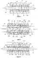
- Figure 1 shows a device which includes two foam segments 4a and 4b where the exhaust flows from the inlet chamber 7 to the outer chamber 8 and from the outer chamber 8 to the exit chamber 9.
- Figure 2 shows a device which includes two foam segments 4a and 4b where the exhaust is forced to flow from the inner chamber 7' via the outer chamber 8' and the closed chamber 13 to the exit chamber 9'.
- Figure 3 shows a device which includes two units assembled in series and sharing a common diaphragm 16. Each unit resembles the embodiment described in Figure 1 .
- Unit “A” shares a common diaphragm 16 with Unit “B”, thus forcing the flow exiting Unit “A” via the exit chamber A9 to enter directly the inlet chamber B7 of Unit “B”. The flow is then forced via the outer chamber B8 and the exit chamber B9 to the outlet pipe 3.
- number 1 designates the metal shell, defining a cavity with an intake pipe 2 and an outlet pipe 3 and two foam segments 4a, 4b made of layered metal foam sheets set in the path of communication between said intake pipe 2 and outlet pipe 3.
- the foam segments 4a, 4b comprise a plurality of metal foam sheets, rolled around perforated tubes 10a, 10b, with a porosity preferably higher than 40%.
- the foam segments 4a and 4b are separated by a diaphragm 5 and are set about the longitudinal axis 6 of the shell 1 in such a way as to define, inside the shell 1, an inlet chamber 7, an outer chamber 8, and an exit chamber 9, the said chambers communicating with said intake pipe 2 and said outlet pipe 3 in such a way that during use, the flow of the engine exhaust gases is forced from the inlet chamber 7 to the outer chamber 8 and from the outer chamber 8 to the exit chamber 9, thus assuming radial components of velocity with respect to the longitudinal axis 6 of the shell 1.
- the porosity of the foam layers is preferably variable. To minimize pressure drop the layers near the perforated tubes should preferably have larger pores and the layers close to the periphery should preferably have smaller pores.
- the foam material is catalytically coated.
- the type and amount of catalytic coating depends on the specific application.
- An important feature of the present device is the possibility of combining different catalytic functionalities in one system, by using different types and/or amounts of catalytic coatings in different foam layers.
- the foam may act at the same time as a particulate filtering device.
- the foam segments 4a, 4b, 12a, 12b are set about the longitudinal axis 6 of the shell 1 in such a way as to define, inside the shell 1, an inner chamber 7, an outer chamber 8, an exit chamber 9, and a closed chamber 13, the said chambers communicating with said intake pipe 2 and said outlet pipe 3 in such a way that during use, the flow of the engine exhaust gases is forced from the inner chamber 7 via the outer chamber 8 and the closed chamber 13 to the exit chamber 9, thus assuming radial components of velocity with respect to the longitudinal axis 6 of the shell 1.
- This design achieves a higher flow cross-section area for the same overall volume with a compromise in filtration depth.
- the exhaust flow is distributed between the primary and the secondary foam segments according to the respective flow resistances.
- the inner and outer dimensions of the main and secondary foam segments can be appropriately designed to achieve the preferred flow distribution, taking into account filtration and pressure drop requirements.
- the porosity of the foams and the catalyst distribution the same considerations apply as already mentioned in the case of Figure 1 .
- Unit “A” comprises two foam segments A4a and A4b separated by a diaphragm A5, the said foam segments being set about the longitudinal axis 6 of the shell 1 in such a way as to define, inside the shell 1, an inlet chamber A7, an outer chamber A8, and an exit chamber A9.
- Unit “B” comprises two foam segments B4a and B4b separated by a diaphragm B5, the said foam segments being set about the longitudinal axis 6 of the shell 1 in such a way as to define, inside the shell 1, an inlet chamber B7, an outer chamber B8, and an exit chamber B9.
Landscapes
- Engineering & Computer Science (AREA)
- Chemical & Material Sciences (AREA)
- Chemical Kinetics & Catalysis (AREA)
- Combustion & Propulsion (AREA)
- Mechanical Engineering (AREA)
- General Engineering & Computer Science (AREA)
- Health & Medical Sciences (AREA)
- Toxicology (AREA)
- Biomedical Technology (AREA)
- Environmental & Geological Engineering (AREA)
- Analytical Chemistry (AREA)
- General Chemical & Material Sciences (AREA)
- Oil, Petroleum & Natural Gas (AREA)
- Geometry (AREA)
- Physics & Mathematics (AREA)
- Exhaust Gas After Treatment (AREA)
- Exhaust Gas Treatment By Means Of Catalyst (AREA)
- Processes For Solid Components From Exhaust (AREA)
- Filtering Materials (AREA)
- Catalysts (AREA)
Abstract
Description
- The present invention relates to devices for gas treatment based on metal foams, in particular an exhaust gas after-treatment device, comprising a metal shell defining a cavity with an intake pipe and an outlet pipe and two foam segments made of layered metal foam sheets set in the path of communication between said intake pipe and outlet pipe.
- The metal foam material considered and the manufacturing process are described in the international patent applications
WO 2004089564 andWO 2005037467 respectively. According to this process, the metal foam is produced in sheets with the desired length and width. - Foam based filters to be used or contained in said devices, are known for diesel particulate filtering applications, although most of them are based on ceramic materials. Typically ceramic foams with sufficiently small pore sizes to achieve good filtration efficiencies exhibit a relatively high pressure drop, due to the large number of closed pores. Moreover, as more soot is accumulated in the filter, such foams are known to lower their filtration efficiency until a "blow-off" behavior, i.e. a negative efficiency, is observed.
- Another drawback of the ceramic foams is the limitation regarding the shaping of the final filter to be used or contained in said devices. Therefore, it is very difficult to obtain a large filtration area in the limited space required in automotive applications.
- From document
WO 01/94010 - Other documents, /./ like
US 3 166 895 orUS 5 484 575 disclose similar solutions, with similar drawbacks as in the case above. -
WO 94/12777 of Flaekt - In the known prior art, the material proposed is generally referred to as porous metal, without specifically detailing the production process.
- Document
DE 10 2005 010248 discloses a fabrication method for a metal foam, but the produced metal foam from this method still presents similar drawbacks, in addition to the "blow-off' behavior. - Besides, some known embodiments are defined by the need to support the thermal regeneration of the filters via the usage of electrical heaters. Therefore the usage of at least two cylindrical filter elements is called for. Due to the limitations related with the material, the production process of the filter elements and of the need of multiple filter elements, the thickness of the filter elements is restricted in the
region 0,5 to 20 mm, preferably 1 mm or more. - The pore size range proposed to be used particularly preferably from 100 to 600 µm is fairly small. Similarly the filtration thicknesses are very narrow.
- A still further known prior art relates to the use of ceramic foams resulting in that they do not provide a solution to solve the aforementioned drawbacks.
-
US 4 175 107 of Fukada yet discloses a catalytic converter for purifying the exhaust gases from an internal combustion engine. It discloses inlet, outer and exit chambers, but the flow can go any way, and it further discloses catalytic elements. -
EP 1344907 A1 discloses a device consisting of a body with open cell or open pores structure, for example made of metal foam or metal pot scourer with open pores with a porosity comprised between 20 and 100 pores per Inch, which is determined by the amount of pores along a line. The porosity may have different values, but one single value at the time for a certain device. In addition, it tends to solve a problem of providing a device oxidizing soot at lowest possible temperature that is equipped against blocking. - The purpose of the present invention is to remedy the aforementioned drawbacks and the application field of the present invention is targeted mainly in the area of catalytic substrates for gasoline and diesel engine exhaust after treatment.
- There is thus proposed according to the present invention a device as defined in
claim 1. /./ - According to a further main embodiment of the invention, there is proposed an exhaust gas after-treatment device further comprising two secondary foam segments made of layered metal foam sheets set in the path of communication between said intake pipe and outlet pipe, in addition to the main said two foam segments. Said device is remarkable in that said two secondary foam segments also comprise a plurality of layers of metal foam sheets, which are set about the longitudinal axis of the shell in such a way as to define, inside the shell, an inner chamber, an outer chamber, an exit chamber, and a closed chamber, wherein said chambers communicate with said intake, resp. outlet pipes in such a way that during use, the flow of the engine exhaust gases is forced from the inner chamber via the outer chamber and the closed chamber to the exit chamber, thus assuming radial components of velocity with respect to the longitudinal axis of the shell.
- According to an advantageous embodiment of the invention, said foam segments of said device are composed of concentric layers of metal foam sheets.
- According to a still further advantageous embodiment of the invention, the foam segments are rolled around perforated tubes.
- According to a particular embodiment of the invention, the respective diameters of said perforated tubes are different.
- According to a more particular embodiment of the invention, the perforation of the perforated tubes is locally variable.
- According to a preferred embodiment of the invention, the metal foam layers are coated with catalytically active material.
- According to a further preferred embodiment of the invention, the catalytic loading of the metal foam layers is variable in any direction.
- According to a specific embodiment of the present invention, said diaphragm has a disc shape with its external diameter assuming any value larger than the diameter of the perforated tubes and lower than the diameter of the outer shell.
- According to a more specific embodiment of the present invention said diaphragm is perforated.
- According to a still more specific embodiment of the present invention said perforation of diaphragm is locally variable.
- According to a further embodiment of the invention, said perforated tube is closed at its one end by a disc-shaped diaphragm and at its opposite end by a disc-shaped diaphragm, thus forcing the flow of gas entering the inner chamber to pass via the outer chamber and the closed chamber to the exit chamber, which communicates with the outlet pipe.
- According to a still further embodiment of the invention, each foam sheet is made of a metal alloy, with suitable mechanical properties to allow forming in tubular design.
- The present invention also relates to an engine exhaust after-treatment system comprising a plurality of combinations, each including a device as set out above in serial arrangements.
- Alternatively, the present invention relates to an engine exhaust after-treatment system comprising a plurality of combinations, each including a device as set out above in parallel arrangements.
- Still alternatively the present invention relates to an engine exhaust after-treatment system comprising a plurality of combinations, each including a device as set out above in both serial, resp. parallel arrangements.
- According to a specific embodiment, the system according to the present invention further comprises a conduit having a cavity defined by an inner surface and wherein each combination is received in the cavity.
- The metal foam offers a high specific surface area for application of catalytic coatings. In addition, the foam structure enhances the gas mixing and mass transfer rates between the gas and the catalytic surface. An additional property of the metal foam as catalyst substrate is its potential to filter particulate matter from the exhaust gas, which is important in the case of diesel and direct injection gasoline engines. Due to the above properties, the metal foam presents advantages compared to the widely used honeycomb substrates. On the other hand, the flow resistance of metal foams depends strongly on their internal structure. To obtain acceptable pressure drop with a foam substrate, it is necessary to optimize both the microstructure - e.g. pore size - and the macro-structure, e.g. external geometry. The present invention addresses the issue of such a design optimization.
- The pressure drop can be reduced by lowering the gas velocities, which is possible by a large cross-section area. A large cross-section area can be obtained if the foam is shaped in a tubular configuration in such a way as to be radially traversed by the exhaust gas flow. This is technically possible in the case of the metal foam considered in the present invention.
- In some applications the primary requirement is that the exhaust aftertreatment device shall not block the engine by exerting an extremely high backpressure. Such high backpressure will occur in any filter accumulating soot with high efficiency and operating under low temperature conditions (100-250 °C), typically met in urban driving. One possibility to avoid this is to use foams that exhibit a decreasing filtration efficiency as soot loading increases. Such a device will tend to equilibrate ("zero efficiency") at an acceptable backpressure level for the engine. Using a carefully selected combination of foam porosities, it is possible to design the device in such a way as to reach the aforementioned target.
- Depending on the application, the metal foams can be coated with any catalytically active material. Possible applications cover diesel oxidation catalysts, "3-way" catalysts, lean NOx catalysts and traps, NOx Selective Catalytic Reduction. The catalytic coating could also be used to enhance the oxidation rate of the accumulated soot in filtration devices.
- The purpose of the invention is accomplished based on a tubular design, where the flow is forced to pass through in the transverse direction several times, using diaphragms to guide the flow. The specific design makes maximum use of the available - usually restricted - volume in such a way as to achieve a good compromise between low gas velocity, sufficient filtration depth and acceptable backpressure.
- A large filtration area could be obtained if the filter is shaped in a tubular configuration in such a way as to be radially traversed by the exhaust gas flow. This is technically possible in the case of the metal foam to be considered in the device according to the present invention.
- In an alternative embodiment, an additional (secondary) foam tube is placed within the metal support of the primary foam segment. The diaphragms are designed in such a way as to allow the flow to be divided between the main and the secondary foam segment according to the respective flow resistances. This configuration further increases the flow area for a given available volume, providing additional pressure drop benefits. This may be done with a compromise in the overall foam thickness. The resulting adverse effect on filtration efficiency could be minimized by appropriate selection of the foam porosity.
- The pore size of the foam may vary in the range between 400 and 1800 microns. The thickness of each foam sheet is approximately 1,5 mm for the lowest pore sizes and approximately 4 mm for the largest pore sizes. This foam can be easily shaped to form cylindrical structures by rolling. Moreover, the foam can be easily coated with catalytically active materials typically used in automotive applications.
- Further features of the present invention are set out in additional sub-claims.
- Unlike most commercialized diesel particulate filters, which work based on the surface filtration mechanism, foam filters operate based on deep-bed filtration. This means that the soot is collected within the foam structure rather than on its surface. Based on current experience based on engine testing, a highly efficient filter with small pores will tend to accumulate much more soot near its entrance rather than towards its exit. This non-uniform soot distribution is not favorable since the highly-loaded regions of the filter will increase the pressure drop non-proportionally. On the other hand, a more uniform distribution can be accomplished using a combination of various foam structures, with larger pores near the entrance and progressively smaller pores near the exit. This configuration referred to as "porosity gradient" is technically feasible with the metal foam material considered here, which is not the case for ceramic foams.
- Real-world testing so far has shown that a deep-bed based particulate filtration efficiency of the order of 80 to 95% is possible with acceptable pressure drop using a coated foam filter appropriately shaped to allow flow direction in a radial direction. Due to the governing diffusion-based filtration mechanism, the filtration efficiency is highest (close to 100%) for the smaller particle sizes (<20nm). It is assessed that the soot capacity limit of the filter may exceed 15 grams/liter, which is almost double compared to standard wall-flow systems. The regeneration potential of this filter at low temperatures (between 250-450°C) has proven to be superior compared to standard catalyzed ceramic wall-flow filters. The catalytic coating is also able to attain a near 100% conversion of CO and hydrocarbons at temperatures of the order of 200°C. At the same time, the foam based filters with pore size of 600 microns or less exhibit no tendency for blowing-off the accumulated soot during any possible realistic driving condition.
- Some exemplary embodiments of the device according to the present invention are further described more in detail in the description hereafter, which are further illustrated by the appended drawings, wherein same numerals refer to similar or identical elements.
-
-
Figure 1 illustrates a first embodiment of the invention. -
Figure 2 illustrates a second embodiment of the invention. -
Figure 3 illustrates a third embodiment of the invention. -
Figure 1 shows a device which includes twofoam segments inlet chamber 7 to theouter chamber 8 and from theouter chamber 8 to theexit chamber 9. -
Figure 2 shows a device which includes twofoam segments closed chamber 13 to the exit chamber 9'. -
Figure 3 shows a device which includes two units assembled in series and sharing acommon diaphragm 16. Each unit resembles the embodiment described inFigure 1 . Unit "A" shares acommon diaphragm 16 with Unit "B", thus forcing the flow exiting Unit "A" via the exit chamber A9 to enter directly the inlet chamber B7 of Unit "B". The flow is then forced via the outer chamber B8 and the exit chamber B9 to theoutlet pipe 3. - Similar to the embodiment described in
Figure 3 , further possible embodiments are possible by assembling more than two units in series and/or in parallel. - With reference to
Figure 1 ,number 1 designates the metal shell, defining a cavity with anintake pipe 2 and anoutlet pipe 3 and twofoam segments intake pipe 2 andoutlet pipe 3. - In
Figure 1 , thefoam segments perforated tubes - The
foam segments diaphragm 5 and are set about thelongitudinal axis 6 of theshell 1 in such a way as to define, inside theshell 1, aninlet chamber 7, anouter chamber 8, and anexit chamber 9, the said chambers communicating with saidintake pipe 2 and saidoutlet pipe 3 in such a way that during use, the flow of the engine exhaust gases is forced from theinlet chamber 7 to theouter chamber 8 and from theouter chamber 8 to theexit chamber 9, thus assuming radial components of velocity with respect to thelongitudinal axis 6 of theshell 1. The porosity of the foam layers is preferably variable. To minimize pressure drop the layers near the perforated tubes should preferably have larger pores and the layers close to the periphery should preferably have smaller pores. - In most applications the foam material is catalytically coated. The type and amount of catalytic coating depends on the specific application. An important feature of the present device is the possibility of combining different catalytic functionalities in one system, by using different types and/or amounts of catalytic coatings in different foam layers. In addition, the foam may act at the same time as a particulate filtering device.
- In the variation of the design shown in
Figure 2 , thefoam segments longitudinal axis 6 of theshell 1 in such a way as to define, inside theshell 1, aninner chamber 7, anouter chamber 8, anexit chamber 9, and aclosed chamber 13, the said chambers communicating with saidintake pipe 2 and saidoutlet pipe 3 in such a way that during use, the flow of the engine exhaust gases is forced from theinner chamber 7 via theouter chamber 8 and theclosed chamber 13 to theexit chamber 9, thus assuming radial components of velocity with respect to thelongitudinal axis 6 of theshell 1. - This design achieves a higher flow cross-section area for the same overall volume with a compromise in filtration depth. The exhaust flow is distributed between the primary and the secondary foam segments according to the respective flow resistances. The inner and outer dimensions of the main and secondary foam segments can be appropriately designed to achieve the preferred flow distribution, taking into account filtration and pressure drop requirements. As regards the porosity of the foams and the catalyst distribution, the same considerations apply as already mentioned in the case of
Figure 1 . - In the variation of the design shown in
Figure 3 , two units are assembled in series, sharing acommon diaphragm 16. Unit "A" comprises two foam segments A4a and A4b separated by a diaphragm A5, the said foam segments being set about thelongitudinal axis 6 of theshell 1 in such a way as to define, inside theshell 1, an inlet chamber A7, an outer chamber A8, and an exit chamber A9. Unit "B" comprises two foam segments B4a and B4b separated by a diaphragm B5, the said foam segments being set about thelongitudinal axis 6 of theshell 1 in such a way as to define, inside theshell 1, an inlet chamber B7, an outer chamber B8, and an exit chamber B9. - The flow of the engine exhaust gases entering Unit "A" via the
intake pipe 2 is forced from the inner chamber A7 via the outer chamber A8 to the exit chamber A9, thus assuming radial components of velocity with respect to thelongitudinal axis 6 of theshell 1. Unit "A" shares acommon diaphragm 16 with Unit "B", thus forcing the flow exiting Unit "A" via the exit chamber A9 to enter directly the inlet chamber B7 of Unit "B". The flow is then forced via the outer chamber B8 and the exit chamber B9 to theoutlet pipe 3, thus assuming radial components of velocity with respect to thelongitudinal axis 6 of theshell 1.
Claims (14)
- An exhaust gas after-treatment device, comprising a metal shell (1) defining a cavity with an intake pipe (2) and an outlet pipe (3) and two foam segments (4a; 4b) that are separated by a diaphragm (5), which are set about the longitudinal axis (6) of the shell (1) in such a way as to define, inside the shell (1), an inlet chamber (7), an outer chamber (8), and an exit chamber (9), the said chambers communicating with said intake pipe (2) and said outlet pipe (3) in such a way that during use, the flow of the engine exhaust gases is forced from the inlet chamber (7) to the outer chamber (8) and from the outer chamber (8) to the exit chamber (9), thus assuming radial components of velocity with respect to the longitudinal axis (6) of the shell (1), characterized in that- said two segments (4a; 4b) are metal foam segments ;- in that said two segments (4a; 4b) are made of layered metal foam sheets set in the path of communication between said intake pipe (2) and outlet pipe (3), each (4a; 4b) comprising a plurality of layers of metal foam sheets; and- in that said porosity of the metal foam layers is variable in different points of said metal foam sheets.
- An exhaust gas after-treatment device according to claim 1, comprising two secondary foam segments (12a; 12b) made of layered metal foam sheets set in the path of communication between said intake pipe (2) and outlet pipe (3), in addition to said main said two foam segments (4a; 4b), characterized in that said two secondary foam segments (12a, 12b) also comprise a plurality of layers of metal foam sheets, which are set about the longitudinal axis (6) of the shell (1) in such a way as to define, inside the shell (1), an inner chamber (7'), an outer chamber (8'), an exit chamber (9'), and a closed chamber (13), the said chambers communicating with said intake pipe (2) and said outlet pipe (3) in such a way that during use, the flow of the engine exhaust gases is forced from the inner chamber (7') via the outer chamber (8') and the closed chamber (13) to the exit chamber (9'), thus assuming radial components of velocity with respect to the longitudinal axis (6) of the shell (1).
- The device according to claim 1 or 2, characterized in that the foam segments (4a; 4b) and/or (12a; 12b) are composed of concentric layers of metal foam sheets.
- The device according to one of the preceding claims, characterized in that the foam segments (4a; 4b) and (12a; 12b) are rolled around perforated tubes (10a; 10b), respectively (15a; 15b).
- The device according to claim 4, characterized in that the respective diameters of said perforated tubes (10a; 15a) and (10b; 15b) are different.
- The device according to one of the claims 5 to 7, characterized in that the perforation of the perforated tubes (10a; 15a) and (10b; 15b) is variable in a limited area.
- The device according to one of the preceding claims, characterized in that the metal foam layers are coated with catalytically active material.
- The device according to the preceding claim, characterized in that the catalytic loading of the metal foam layers is variable in different points of said metal foam sheet layers.
- The device according to one of claims 4 to 8, characterized in that said diaphragm (5) has a disc shape with its external diameter assuming any value larger than the diameter of the perforated tubes (10a; 15a) and (10b; 15b) and lower than the diameter of the outer shell (1).
- The device according to one of the preceding claims, characterized in that said diaphragm (5) is perforated, in particular with a variable perforation in a limited area.
- The device according to one of the claims 4 to 10, when depending on Claim 2, characterized in that said perforated tube (15a) is closed at its one end by a disc-shaped diaphragm (11) and at its opposite end by a disc-shaped diaphragm (14) thus forcing the flow of gas entering the inner chamber (7') to pass via the outer chamber (8') and the closed chamber (13) to the exit chamber (9'), which communicates with the outlet pipe (3).
- The device according to any one of the preceding claims, characterized in that each foam sheet is made of a metal alloy, with suitable mechanical properties to allow forming in tubular design.
- An engine exhaust after-treatment system comprising a plurality of combinations, each including a device according to one of the preceding claims in serial arrangements, and/or in parallel arrangements.
- The system according to the preceding claim further comprising a conduit having a cavity defined by an inner surface and wherein each combination is received in the cavity.
Priority Applications (1)
| Application Number | Priority Date | Filing Date | Title |
|---|---|---|---|
| PL07804509T PL2066879T3 (en) | 2006-09-20 | 2007-09-20 | Gas treatment device |
Applications Claiming Priority (2)
| Application Number | Priority Date | Filing Date | Title |
|---|---|---|---|
| GR20060100530A GR1005756B (en) | 2006-09-20 | 2006-09-20 | Gas treatment device. |
| PCT/GR2007/000048 WO2008035127A1 (en) | 2006-09-20 | 2007-09-20 | Gas treatment device |
Publications (2)
| Publication Number | Publication Date |
|---|---|
| EP2066879A1 EP2066879A1 (en) | 2009-06-10 |
| EP2066879B1 true EP2066879B1 (en) | 2012-08-01 |
Family
ID=38925497
Family Applications (1)
| Application Number | Title | Priority Date | Filing Date |
|---|---|---|---|
| EP07804509A Not-in-force EP2066879B1 (en) | 2006-09-20 | 2007-09-20 | Gas treatment device |
Country Status (13)
| Country | Link |
|---|---|
| US (1) | US8236250B2 (en) |
| EP (1) | EP2066879B1 (en) |
| JP (2) | JP2010504466A (en) |
| KR (1) | KR101553867B1 (en) |
| CN (1) | CN101595283B (en) |
| AU (1) | AU2007298750B2 (en) |
| BR (1) | BRPI0715310A2 (en) |
| CA (1) | CA2671902A1 (en) |
| DK (1) | DK2066879T3 (en) |
| ES (1) | ES2392358T3 (en) |
| GR (1) | GR1005756B (en) |
| PL (1) | PL2066879T3 (en) |
| WO (1) | WO2008035127A1 (en) |
Families Citing this family (16)
| Publication number | Priority date | Publication date | Assignee | Title |
|---|---|---|---|---|
| CN102305117B (en) * | 2010-05-25 | 2014-03-05 | 宋殿麒 | Burn-off cylinder, namely smoke purification device, for internal combustion engine |
| ITRE20110017A1 (en) * | 2011-03-25 | 2012-09-26 | Ufi Innovation Ct Srl | FILTERING GROUP FOR FLUIDS |
| DE102012004270A1 (en) * | 2012-03-02 | 2013-09-05 | Emitec Gesellschaft Für Emissionstechnologie Mbh | Apparatus for treating a gas flow flowing radially outwards from a central region |
| KR101416478B1 (en) * | 2012-08-17 | 2014-07-09 | 세종공업 주식회사 | Mixing module for post treatment exhaust contamination gas decreasing system in diesel engine |
| WO2014113540A1 (en) | 2013-01-16 | 2014-07-24 | Iowa State University Research Foundation, Inc. | A deep intronic target for splicing correction on spinal muscular atrophy gene |
| CN104289159B (en) * | 2013-07-15 | 2016-04-13 | 浙江大学 | A kind of device being filled with the structural catalyst of radial wall stream |
| CN103736328B (en) * | 2013-12-13 | 2015-11-04 | 科迈(常州)电子有限公司 | A kind of air filter of oxygenerator |
| CN104594981B (en) * | 2014-11-29 | 2017-01-11 | 中国煤炭科工集团太原研究院有限公司 | Efficient tail gas particle purification system of mining rubber-tyred vehicle |
| CN108472583A (en) * | 2015-12-22 | 2018-08-31 | 国际壳牌研究有限公司 | A kind of reactor for reducing nitrogen oxides |
| CN106975344A (en) * | 2016-08-31 | 2017-07-25 | 海南兴能泰环境科技有限公司 | Modularization administers the catalyzing, oxidizing and purifying method and device of high-concentration sulfur-containing waste gas |
| CN107671098A (en) * | 2017-09-08 | 2018-02-09 | 合肥惠科金扬科技有限公司 | A kind of dustless clean operating room of AMOLED liquid crystal displays processing |
| IT201800006072A1 (en) * | 2018-06-06 | 2019-12-06 | AIR FILTRATION DEVICE | |
| CN109224690A (en) * | 2018-10-18 | 2019-01-18 | 文露 | A kind of environmental protection chemical industry tail gas processing equipment |
| US11322347B2 (en) | 2018-12-14 | 2022-05-03 | Applied Materials, Inc. | Conformal oxidation processes for 3D NAND |
| CN113750664B (en) * | 2021-08-31 | 2023-02-28 | 成都易态科技有限公司 | Filter and dust removal method |
| CN115672007B (en) * | 2022-10-14 | 2025-06-17 | 安徽顺达环保科技股份有限公司 | A high-efficiency, fully dry dust removal hood for boiler high-sulfur flue gas and its implementation method |
Family Cites Families (24)
| Publication number | Priority date | Publication date | Assignee | Title |
|---|---|---|---|---|
| US3166895A (en) | 1960-06-10 | 1965-01-26 | Owens Corning Fiberglass Corp | Catalytic muffling system for reducing contaminants in exhaust gases |
| GB1519343A (en) | 1974-09-03 | 1978-07-26 | Matsushita Electric Industrial Co Ltd | Gas purifying devices |
| US4913712A (en) * | 1987-11-18 | 1990-04-03 | Swiss Aluminium Ltd. | Filter for cleaning exhaust gases of diesel engines |
| DE3910554A1 (en) | 1988-04-11 | 1989-10-19 | Volkswagen Ag | PARTICLE FILTER CONSTRUCTED USING ONE-SIDED SEALED PUNCHED TUBES |
| FI921889A7 (en) | 1991-05-02 | 1992-11-03 | Scambia Ind Dev Ag | KATALYSATOR FOER KATALYTISK BEHANDLING AV AVGASER |
| SE9203604D0 (en) * | 1992-12-01 | 1992-12-01 | Abb Flaekt Marine Ab | DEVICE FOR HETROGEN CATALYSIS |
| US5512250A (en) * | 1994-03-02 | 1996-04-30 | Catalytica, Inc. | Catalyst structure employing integral heat exchange |
| JPH08243330A (en) * | 1995-03-13 | 1996-09-24 | Toyota Autom Loom Works Ltd | Filter |
| JPH09108570A (en) * | 1995-10-19 | 1997-04-28 | Toyota Motor Corp | Exhaust gas purification oxidation catalyst and method for producing the same |
| JPH10121941A (en) * | 1996-10-18 | 1998-05-12 | Sumitomo Electric Ind Ltd | Exhaust gas purification device |
| JPH10131739A (en) * | 1996-10-28 | 1998-05-19 | Sumitomo Electric Ind Ltd | Exhaust gas purification device |
| JPH10176519A (en) * | 1996-12-18 | 1998-06-30 | Sumitomo Electric Ind Ltd | Particulate trap for diesel engine |
| DE19704147A1 (en) * | 1997-02-04 | 1998-08-06 | Emitec Emissionstechnologie | Heat-resistant and regenerable filter body with flow paths |
| JP3445775B2 (en) * | 2000-02-22 | 2003-09-08 | トヨタ自動車株式会社 | Particulate filter |
| DE60132082T2 (en) | 2000-06-02 | 2008-12-11 | Basf Catalysts Llc | FOLDABLE METAL CATALYST SUPPORT AND MADE OF IT, FORMABLE CATALYST ELEMENTS AND METHOD FOR THE INSTALLATION THEREOF |
| JP2001355431A (en) * | 2000-06-16 | 2001-12-26 | Isuzu Motors Ltd | Diesel engine exhaust purification system |
| EP1344907A1 (en) | 2002-03-12 | 2003-09-17 | Capital Technology GmbH | Device for removing carbon particles from exhaust gases |
| DE10257113A1 (en) * | 2002-12-05 | 2004-06-24 | Emitec Gesellschaft Für Emissionstechnologie Mbh | Particle trap with coated fiber layer |
| DE10316929B3 (en) | 2003-04-07 | 2004-09-16 | Fraunhofer-Gesellschaft zur Förderung der angewandten Forschung e.V. | Production of open-pore molded body, used as particle filter, involves coating open pore body made from nickel or iron with metal powder, to form mixed crystals or intermetallic phases using organic binder, and further processing |
| FI118418B (en) * | 2003-04-17 | 2007-11-15 | Ecocat Oy | Aluminum-rounded catalytic converter for cleaning of gas leaks |
| JP4339049B2 (en) * | 2003-08-29 | 2009-10-07 | 日新電機株式会社 | Exhaust gas treatment method and exhaust gas treatment apparatus |
| DE10346281B4 (en) | 2003-09-30 | 2006-06-22 | Fraunhofer-Gesellschaft zur Förderung der angewandten Forschung e.V. | Method for producing components with a nickel-based alloy and components produced therewith |
| DE102005010248B4 (en) | 2005-02-28 | 2006-10-26 | Fraunhofer-Gesellschaft zur Förderung der angewandten Forschung e.V. | Process for producing an open-pored metal foam body, a metal foam body produced in this way and its uses |
| DE202005010248U1 (en) | 2005-06-30 | 2005-09-08 | Tss Technische Sicherheits-Systeme Gmbh | Concrete crash barrier system for motor transport has a graduated concrete guard wall with lower, middle and upper steps and at least two reinforcement bars in the upper step, and is supported without anchoring to the road |
-
2006
- 2006-09-20 GR GR20060100530A patent/GR1005756B/en not_active IP Right Cessation
-
2007
- 2007-09-20 US US12/311,195 patent/US8236250B2/en not_active Expired - Fee Related
- 2007-09-20 PL PL07804509T patent/PL2066879T3/en unknown
- 2007-09-20 KR KR1020097008074A patent/KR101553867B1/en not_active Expired - Fee Related
- 2007-09-20 WO PCT/GR2007/000048 patent/WO2008035127A1/en not_active Ceased
- 2007-09-20 CN CN2007800391287A patent/CN101595283B/en not_active Expired - Fee Related
- 2007-09-20 JP JP2009528799A patent/JP2010504466A/en active Pending
- 2007-09-20 BR BRPI0715310-4A patent/BRPI0715310A2/en not_active Application Discontinuation
- 2007-09-20 EP EP07804509A patent/EP2066879B1/en not_active Not-in-force
- 2007-09-20 CA CA002671902A patent/CA2671902A1/en not_active Abandoned
- 2007-09-20 ES ES07804509T patent/ES2392358T3/en active Active
- 2007-09-20 AU AU2007298750A patent/AU2007298750B2/en not_active Ceased
- 2007-09-20 DK DK07804509.3T patent/DK2066879T3/en active
-
2013
- 2013-02-08 JP JP2013023247A patent/JP5902634B2/en not_active Expired - Fee Related
Also Published As
| Publication number | Publication date |
|---|---|
| BRPI0715310A2 (en) | 2013-07-09 |
| US8236250B2 (en) | 2012-08-07 |
| GR1005756B (en) | 2007-12-20 |
| PL2066879T3 (en) | 2013-03-29 |
| KR101553867B1 (en) | 2015-09-17 |
| AU2007298750A1 (en) | 2008-03-27 |
| WO2008035127A8 (en) | 2009-06-11 |
| WO2008035127A1 (en) | 2008-03-27 |
| DK2066879T3 (en) | 2012-11-05 |
| CA2671902A1 (en) | 2008-03-27 |
| JP2013151939A (en) | 2013-08-08 |
| CN101595283B (en) | 2012-12-05 |
| KR20090094222A (en) | 2009-09-04 |
| CN101595283A (en) | 2009-12-02 |
| US20100003171A1 (en) | 2010-01-07 |
| EP2066879A1 (en) | 2009-06-10 |
| JP5902634B2 (en) | 2016-04-13 |
| ES2392358T3 (en) | 2012-12-10 |
| JP2010504466A (en) | 2010-02-12 |
| AU2007298750B2 (en) | 2014-01-30 |
Similar Documents
| Publication | Publication Date | Title |
|---|---|---|
| AU2007298750B2 (en) | Gas treatment device | |
| US7935163B2 (en) | Filtering device for diesel engine exhaust gas | |
| EP2175114B1 (en) | Exhaust emission control device | |
| CN101801499B (en) | Tuning particulate filter performance through selective plugging and use of multiple particulate filters to reduce emissions and improve thermal robustness | |
| US7211232B1 (en) | Refractory exhaust filtering method and apparatus | |
| JP4709138B2 (en) | Porous sheet and substrate having one or more porous sheets for treating exhaust gases of combustion engine | |
| JP2000508585A (en) | Heat resistant renewable filter body with flow path | |
| JPS62103410A (en) | Cleaning filter for exhaust | |
| JP2006502842A (en) | Exhaust gas aftertreatment device | |
| EP2435673A2 (en) | Particulate filter with low soot loaded coating | |
| EP1485590B1 (en) | A device for treatment of a gas flow | |
| US20060078479A1 (en) | Filter assembly for an exhaust treatment device | |
| JP4382517B2 (en) | Oxidation catalyst type exhaust gas purification device | |
| JP2007138875A (en) | Exhaust gas purification system and purification method | |
| JP4358054B2 (en) | Exhaust gas purification honeycomb structure | |
| JP6590035B2 (en) | Exhaust gas purification substrate |
Legal Events
| Date | Code | Title | Description |
|---|---|---|---|
| PUAI | Public reference made under article 153(3) epc to a published international application that has entered the european phase |
Free format text: ORIGINAL CODE: 0009012 |
|
| 17P | Request for examination filed |
Effective date: 20090402 |
|
| AK | Designated contracting states |
Kind code of ref document: A1 Designated state(s): AT BE BG CH CY CZ DE DK EE ES FI FR GB GR HU IE IS IT LI LT LU LV MC MT NL PL PT RO SE SI SK TR |
|
| AX | Request for extension of the european patent |
Extension state: AL BA HR MK RS |
|
| 17Q | First examination report despatched |
Effective date: 20090720 |
|
| RAP1 | Party data changed (applicant data changed or rights of an application transferred) |
Owner name: ARISTOTLE UNIVERSITY OF THESSALONIKI Owner name: SAMARAS, ZISSIS Owner name: KOLTSAKIS, GRIGORIOS |
|
| GRAP | Despatch of communication of intention to grant a patent |
Free format text: ORIGINAL CODE: EPIDOSNIGR1 |
|
| DAX | Request for extension of the european patent (deleted) | ||
| GRAS | Grant fee paid |
Free format text: ORIGINAL CODE: EPIDOSNIGR3 |
|
| GRAA | (expected) grant |
Free format text: ORIGINAL CODE: 0009210 |
|
| AK | Designated contracting states |
Kind code of ref document: B1 Designated state(s): AT BE BG CH CY CZ DE DK EE ES FI FR GB GR HU IE IS IT LI LT LU LV MC MT NL PL PT RO SE SI SK TR |
|
| REG | Reference to a national code |
Ref country code: GB Ref legal event code: FG4D |
|
| RAP1 | Party data changed (applicant data changed or rights of an application transferred) |
Owner name: SAMARAS, ZISSIS Owner name: ARISTOTLE UNIVERSITY OF THESSALONIKI-RESEARCH COMM Owner name: KOLTSAKIS, GRIGORIOS |
|
| REG | Reference to a national code |
Ref country code: AT Ref legal event code: REF Ref document number: 568830 Country of ref document: AT Kind code of ref document: T Effective date: 20120815 Ref country code: CH Ref legal event code: EP |
|
| REG | Reference to a national code |
Ref country code: IE Ref legal event code: FG4D |
|
| REG | Reference to a national code |
Ref country code: DE Ref legal event code: R096 Ref document number: 602007024387 Country of ref document: DE Effective date: 20120927 |
|
| REG | Reference to a national code |
Ref country code: DK Ref legal event code: T3 |
|
| REG | Reference to a national code |
Ref country code: SE Ref legal event code: TRGR |
|
| REG | Reference to a national code |
Ref country code: NL Ref legal event code: T3 |
|
| REG | Reference to a national code |
Ref country code: ES Ref legal event code: FG2A Ref document number: 2392358 Country of ref document: ES Kind code of ref document: T3 Effective date: 20121210 |
|
| REG | Reference to a national code |
Ref country code: LT Ref legal event code: MG4D Effective date: 20120801 |
|
| PG25 | Lapsed in a contracting state [announced via postgrant information from national office to epo] |
Ref country code: IS Free format text: LAPSE BECAUSE OF FAILURE TO SUBMIT A TRANSLATION OF THE DESCRIPTION OR TO PAY THE FEE WITHIN THE PRESCRIBED TIME-LIMIT Effective date: 20121201 Ref country code: LT Free format text: LAPSE BECAUSE OF FAILURE TO SUBMIT A TRANSLATION OF THE DESCRIPTION OR TO PAY THE FEE WITHIN THE PRESCRIBED TIME-LIMIT Effective date: 20120801 Ref country code: CY Free format text: LAPSE BECAUSE OF FAILURE TO SUBMIT A TRANSLATION OF THE DESCRIPTION OR TO PAY THE FEE WITHIN THE PRESCRIBED TIME-LIMIT Effective date: 20120801 |
|
| REG | Reference to a national code |
Ref country code: SK Ref legal event code: T3 Ref document number: E 12843 Country of ref document: SK |
|
| PG25 | Lapsed in a contracting state [announced via postgrant information from national office to epo] |
Ref country code: PT Free format text: LAPSE BECAUSE OF FAILURE TO SUBMIT A TRANSLATION OF THE DESCRIPTION OR TO PAY THE FEE WITHIN THE PRESCRIBED TIME-LIMIT Effective date: 20121203 Ref country code: LV Free format text: LAPSE BECAUSE OF FAILURE TO SUBMIT A TRANSLATION OF THE DESCRIPTION OR TO PAY THE FEE WITHIN THE PRESCRIBED TIME-LIMIT Effective date: 20120801 Ref country code: SI Free format text: LAPSE BECAUSE OF FAILURE TO SUBMIT A TRANSLATION OF THE DESCRIPTION OR TO PAY THE FEE WITHIN THE PRESCRIBED TIME-LIMIT Effective date: 20120801 |
|
| REG | Reference to a national code |
Ref country code: GR Ref legal event code: EP Ref document number: 20120402518 Country of ref document: GR Effective date: 20130122 |
|
| REG | Reference to a national code |
Ref country code: PL Ref legal event code: T3 |
|
| PG25 | Lapsed in a contracting state [announced via postgrant information from national office to epo] |
Ref country code: EE Free format text: LAPSE BECAUSE OF FAILURE TO SUBMIT A TRANSLATION OF THE DESCRIPTION OR TO PAY THE FEE WITHIN THE PRESCRIBED TIME-LIMIT Effective date: 20120801 Ref country code: RO Free format text: LAPSE BECAUSE OF FAILURE TO SUBMIT A TRANSLATION OF THE DESCRIPTION OR TO PAY THE FEE WITHIN THE PRESCRIBED TIME-LIMIT Effective date: 20120801 Ref country code: MC Free format text: LAPSE BECAUSE OF NON-PAYMENT OF DUE FEES Effective date: 20120930 |
|
| PLBE | No opposition filed within time limit |
Free format text: ORIGINAL CODE: 0009261 |
|
| STAA | Information on the status of an ep patent application or granted ep patent |
Free format text: STATUS: NO OPPOSITION FILED WITHIN TIME LIMIT |
|
| REG | Reference to a national code |
Ref country code: HU Ref legal event code: AG4A Ref document number: E015554 Country of ref document: HU |
|
| 26N | No opposition filed |
Effective date: 20130503 |
|
| PG25 | Lapsed in a contracting state [announced via postgrant information from national office to epo] |
Ref country code: BG Free format text: LAPSE BECAUSE OF FAILURE TO SUBMIT A TRANSLATION OF THE DESCRIPTION OR TO PAY THE FEE WITHIN THE PRESCRIBED TIME-LIMIT Effective date: 20121101 |
|
| REG | Reference to a national code |
Ref country code: DE Ref legal event code: R097 Ref document number: 602007024387 Country of ref document: DE Effective date: 20130503 |
|
| PG25 | Lapsed in a contracting state [announced via postgrant information from national office to epo] |
Ref country code: MT Free format text: LAPSE BECAUSE OF FAILURE TO SUBMIT A TRANSLATION OF THE DESCRIPTION OR TO PAY THE FEE WITHIN THE PRESCRIBED TIME-LIMIT Effective date: 20120801 |
|
| PG25 | Lapsed in a contracting state [announced via postgrant information from national office to epo] |
Ref country code: LU Free format text: LAPSE BECAUSE OF NON-PAYMENT OF DUE FEES Effective date: 20120920 |
|
| PGFP | Annual fee paid to national office [announced via postgrant information from national office to epo] |
Ref country code: IE Payment date: 20140929 Year of fee payment: 8 Ref country code: DK Payment date: 20140929 Year of fee payment: 8 |
|
| PGFP | Annual fee paid to national office [announced via postgrant information from national office to epo] |
Ref country code: PL Payment date: 20140923 Year of fee payment: 8 Ref country code: TR Payment date: 20140911 Year of fee payment: 8 |
|
| PGFP | Annual fee paid to national office [announced via postgrant information from national office to epo] |
Ref country code: CH Payment date: 20141231 Year of fee payment: 8 |
|
| PGFP | Annual fee paid to national office [announced via postgrant information from national office to epo] |
Ref country code: HU Payment date: 20141218 Year of fee payment: 8 |
|
| REG | Reference to a national code |
Ref country code: FR Ref legal event code: PLFP Year of fee payment: 9 |
|
| PGFP | Annual fee paid to national office [announced via postgrant information from national office to epo] |
Ref country code: FI Payment date: 20150928 Year of fee payment: 9 |
|
| PGFP | Annual fee paid to national office [announced via postgrant information from national office to epo] |
Ref country code: AT Payment date: 20150928 Year of fee payment: 9 |
|
| PGFP | Annual fee paid to national office [announced via postgrant information from national office to epo] |
Ref country code: NL Payment date: 20150925 Year of fee payment: 9 Ref country code: BE Payment date: 20150930 Year of fee payment: 9 |
|
| REG | Reference to a national code |
Ref country code: DK Ref legal event code: EBP Effective date: 20150930 |
|
| PGFP | Annual fee paid to national office [announced via postgrant information from national office to epo] |
Ref country code: SK Payment date: 20160321 Year of fee payment: 9 Ref country code: CZ Payment date: 20160321 Year of fee payment: 9 |
|
| REG | Reference to a national code |
Ref country code: CH Ref legal event code: PL |
|
| REG | Reference to a national code |
Ref country code: IE Ref legal event code: MM4A |
|
| PG25 | Lapsed in a contracting state [announced via postgrant information from national office to epo] |
Ref country code: LI Free format text: LAPSE BECAUSE OF NON-PAYMENT OF DUE FEES Effective date: 20150930 Ref country code: CH Free format text: LAPSE BECAUSE OF NON-PAYMENT OF DUE FEES Effective date: 20150930 Ref country code: IE Free format text: LAPSE BECAUSE OF NON-PAYMENT OF DUE FEES Effective date: 20150920 |
|
| PG25 | Lapsed in a contracting state [announced via postgrant information from national office to epo] |
Ref country code: HU Free format text: LAPSE BECAUSE OF NON-PAYMENT OF DUE FEES Effective date: 20150921 |
|
| REG | Reference to a national code |
Ref country code: FR Ref legal event code: PLFP Year of fee payment: 10 |
|
| PG25 | Lapsed in a contracting state [announced via postgrant information from national office to epo] |
Ref country code: DK Free format text: LAPSE BECAUSE OF NON-PAYMENT OF DUE FEES Effective date: 20150930 |
|
| PG25 | Lapsed in a contracting state [announced via postgrant information from national office to epo] |
Ref country code: PL Free format text: LAPSE BECAUSE OF NON-PAYMENT OF DUE FEES Effective date: 20150920 Ref country code: BE Free format text: LAPSE BECAUSE OF NON-PAYMENT OF DUE FEES Effective date: 20160930 |
|
| PG25 | Lapsed in a contracting state [announced via postgrant information from national office to epo] |
Ref country code: FI Free format text: LAPSE BECAUSE OF NON-PAYMENT OF DUE FEES Effective date: 20160920 |
|
| REG | Reference to a national code |
Ref country code: NL Ref legal event code: MM Effective date: 20161001 |
|
| REG | Reference to a national code |
Ref country code: AT Ref legal event code: MM01 Ref document number: 568830 Country of ref document: AT Kind code of ref document: T Effective date: 20160920 |
|
| PG25 | Lapsed in a contracting state [announced via postgrant information from national office to epo] |
Ref country code: CZ Free format text: LAPSE BECAUSE OF NON-PAYMENT OF DUE FEES Effective date: 20160920 |
|
| REG | Reference to a national code |
Ref country code: SK Ref legal event code: MM4A Ref document number: E 12843 Country of ref document: SK Effective date: 20160920 |
|
| PG25 | Lapsed in a contracting state [announced via postgrant information from national office to epo] |
Ref country code: NL Free format text: LAPSE BECAUSE OF NON-PAYMENT OF DUE FEES Effective date: 20161001 |
|
| PG25 | Lapsed in a contracting state [announced via postgrant information from national office to epo] |
Ref country code: SK Free format text: LAPSE BECAUSE OF NON-PAYMENT OF DUE FEES Effective date: 20160920 |
|
| PG25 | Lapsed in a contracting state [announced via postgrant information from national office to epo] |
Ref country code: AT Free format text: LAPSE BECAUSE OF NON-PAYMENT OF DUE FEES Effective date: 20160920 |
|
| REG | Reference to a national code |
Ref country code: FR Ref legal event code: PLFP Year of fee payment: 11 |
|
| PGFP | Annual fee paid to national office [announced via postgrant information from national office to epo] |
Ref country code: DE Payment date: 20170517 Year of fee payment: 16 |
|
| REG | Reference to a national code |
Ref country code: BE Ref legal event code: MM Effective date: 20160930 |
|
| PGFP | Annual fee paid to national office [announced via postgrant information from national office to epo] |
Ref country code: SE Payment date: 20170927 Year of fee payment: 11 |
|
| REG | Reference to a national code |
Ref country code: FR Ref legal event code: PLFP Year of fee payment: 12 |
|
| REG | Reference to a national code |
Ref country code: ES Ref legal event code: FD2A Effective date: 20181019 |
|
| PGFP | Annual fee paid to national office [announced via postgrant information from national office to epo] |
Ref country code: FR Payment date: 20180928 Year of fee payment: 12 |
|
| PG25 | Lapsed in a contracting state [announced via postgrant information from national office to epo] |
Ref country code: ES Free format text: LAPSE BECAUSE OF NON-PAYMENT OF DUE FEES Effective date: 20170921 |
|
| PGFP | Annual fee paid to national office [announced via postgrant information from national office to epo] |
Ref country code: GB Payment date: 20181031 Year of fee payment: 12 Ref country code: IT Payment date: 20180927 Year of fee payment: 12 |
|
| REG | Reference to a national code |
Ref country code: SE Ref legal event code: EUG |
|
| PG25 | Lapsed in a contracting state [announced via postgrant information from national office to epo] |
Ref country code: SE Free format text: LAPSE BECAUSE OF NON-PAYMENT OF DUE FEES Effective date: 20180921 |
|
| REG | Reference to a national code |
Ref country code: DE Ref legal event code: R119 Ref document number: 602007024387 Country of ref document: DE |
|
| PG25 | Lapsed in a contracting state [announced via postgrant information from national office to epo] |
Ref country code: DE Free format text: LAPSE BECAUSE OF NON-PAYMENT OF DUE FEES Effective date: 20200401 |
|
| PG25 | Lapsed in a contracting state [announced via postgrant information from national office to epo] |
Ref country code: IT Free format text: LAPSE BECAUSE OF NON-PAYMENT OF DUE FEES Effective date: 20190920 |
|
| GBPC | Gb: european patent ceased through non-payment of renewal fee |
Effective date: 20190920 |
|
| PG25 | Lapsed in a contracting state [announced via postgrant information from national office to epo] |
Ref country code: FR Free format text: LAPSE BECAUSE OF NON-PAYMENT OF DUE FEES Effective date: 20190930 Ref country code: GB Free format text: LAPSE BECAUSE OF NON-PAYMENT OF DUE FEES Effective date: 20190920 |
|
| PGFP | Annual fee paid to national office [announced via postgrant information from national office to epo] |
Ref country code: GR Payment date: 20201029 Year of fee payment: 14 |
|
| PG25 | Lapsed in a contracting state [announced via postgrant information from national office to epo] |
Ref country code: TR Free format text: LAPSE BECAUSE OF NON-PAYMENT OF DUE FEES Effective date: 20160920 |
|
| PG25 | Lapsed in a contracting state [announced via postgrant information from national office to epo] |
Ref country code: GR Free format text: LAPSE BECAUSE OF NON-PAYMENT OF DUE FEES Effective date: 20220407 |