EP2066372B1 - Tragbare hautpflasterartige infusionspumpen - Google Patents
Tragbare hautpflasterartige infusionspumpen Download PDFInfo
- Publication number
- EP2066372B1 EP2066372B1 EP07814329A EP07814329A EP2066372B1 EP 2066372 B1 EP2066372 B1 EP 2066372B1 EP 07814329 A EP07814329 A EP 07814329A EP 07814329 A EP07814329 A EP 07814329A EP 2066372 B1 EP2066372 B1 EP 2066372B1
- Authority
- EP
- European Patent Office
- Prior art keywords
- housing portion
- piston
- user
- reservoir
- disposable housing
- Prior art date
- Legal status (The legal status is an assumption and is not a legal conclusion. Google has not performed a legal analysis and makes no representation as to the accuracy of the status listed.)
- Active
Links
- 238000001802 infusion Methods 0.000 title claims description 79
- 239000007933 dermal patch Substances 0.000 title 1
- 239000012530 fluid Substances 0.000 claims description 72
- 230000033001 locomotion Effects 0.000 claims description 55
- 238000004891 communication Methods 0.000 claims description 51
- 238000002347 injection Methods 0.000 claims description 45
- 239000007924 injection Substances 0.000 claims description 45
- 230000008878 coupling Effects 0.000 claims description 8
- 238000010168 coupling process Methods 0.000 claims description 8
- 238000005859 coupling reaction Methods 0.000 claims description 8
- 230000003247 decreasing effect Effects 0.000 claims 1
- 239000000463 material Substances 0.000 description 46
- NOESYZHRGYRDHS-UHFFFAOYSA-N insulin Chemical compound N1C(=O)C(NC(=O)C(CCC(N)=O)NC(=O)C(CCC(O)=O)NC(=O)C(C(C)C)NC(=O)C(NC(=O)CN)C(C)CC)CSSCC(C(NC(CO)C(=O)NC(CC(C)C)C(=O)NC(CC=2C=CC(O)=CC=2)C(=O)NC(CCC(N)=O)C(=O)NC(CC(C)C)C(=O)NC(CCC(O)=O)C(=O)NC(CC(N)=O)C(=O)NC(CC=2C=CC(O)=CC=2)C(=O)NC(CSSCC(NC(=O)C(C(C)C)NC(=O)C(CC(C)C)NC(=O)C(CC=2C=CC(O)=CC=2)NC(=O)C(CC(C)C)NC(=O)C(C)NC(=O)C(CCC(O)=O)NC(=O)C(C(C)C)NC(=O)C(CC(C)C)NC(=O)C(CC=2NC=NC=2)NC(=O)C(CO)NC(=O)CNC2=O)C(=O)NCC(=O)NC(CCC(O)=O)C(=O)NC(CCCNC(N)=N)C(=O)NCC(=O)NC(CC=3C=CC=CC=3)C(=O)NC(CC=3C=CC=CC=3)C(=O)NC(CC=3C=CC(O)=CC=3)C(=O)NC(C(C)O)C(=O)N3C(CCC3)C(=O)NC(CCCCN)C(=O)NC(C)C(O)=O)C(=O)NC(CC(N)=O)C(O)=O)=O)NC(=O)C(C(C)CC)NC(=O)C(CO)NC(=O)C(C(C)O)NC(=O)C1CSSCC2NC(=O)C(CC(C)C)NC(=O)C(NC(=O)C(CCC(N)=O)NC(=O)C(CC(N)=O)NC(=O)C(NC(=O)C(N)CC=1C=CC=CC=1)C(C)C)CC1=CN=CN1 NOESYZHRGYRDHS-UHFFFAOYSA-N 0.000 description 30
- 238000000034 method Methods 0.000 description 30
- 239000000853 adhesive Substances 0.000 description 26
- 230000001070 adhesive effect Effects 0.000 description 26
- 229910001285 shape-memory alloy Inorganic materials 0.000 description 26
- 238000003780 insertion Methods 0.000 description 25
- 230000037431 insertion Effects 0.000 description 25
- 239000004033 plastic Substances 0.000 description 19
- 229920003023 plastic Polymers 0.000 description 19
- 102000004877 Insulin Human genes 0.000 description 15
- 108090001061 Insulin Proteins 0.000 description 15
- 229940125396 insulin Drugs 0.000 description 15
- 230000013011 mating Effects 0.000 description 15
- 239000002131 composite material Substances 0.000 description 14
- 229910052751 metal Inorganic materials 0.000 description 14
- 239000002184 metal Substances 0.000 description 14
- 239000000919 ceramic Substances 0.000 description 12
- 229940079593 drug Drugs 0.000 description 12
- 239000003814 drug Substances 0.000 description 12
- 230000007246 mechanism Effects 0.000 description 10
- 238000000926 separation method Methods 0.000 description 10
- 239000013039 cover film Substances 0.000 description 8
- -1 long acting Chemical compound 0.000 description 7
- 230000006870 function Effects 0.000 description 6
- 229920001296 polysiloxane Polymers 0.000 description 6
- 206010012601 diabetes mellitus Diseases 0.000 description 5
- 239000011521 glass Substances 0.000 description 5
- WQZGKKKJIJFFOK-GASJEMHNSA-N Glucose Natural products OC[C@H]1OC(O)[C@H](O)[C@@H](O)[C@@H]1O WQZGKKKJIJFFOK-GASJEMHNSA-N 0.000 description 4
- 239000008280 blood Substances 0.000 description 4
- 210000004369 blood Anatomy 0.000 description 4
- 239000008103 glucose Substances 0.000 description 4
- 239000003978 infusion fluid Substances 0.000 description 4
- 230000008569 process Effects 0.000 description 4
- 238000011282 treatment Methods 0.000 description 4
- 229920013683 Celanese Polymers 0.000 description 3
- 239000003990 capacitor Substances 0.000 description 3
- 230000007423 decrease Effects 0.000 description 3
- 229920001971 elastomer Polymers 0.000 description 3
- 230000007613 environmental effect Effects 0.000 description 3
- 229910001000 nickel titanium Inorganic materials 0.000 description 3
- 230000037452 priming Effects 0.000 description 3
- 239000005060 rubber Substances 0.000 description 3
- 238000003860 storage Methods 0.000 description 3
- 208000017667 Chronic Disease Diseases 0.000 description 2
- 230000008901 benefit Effects 0.000 description 2
- 230000008859 change Effects 0.000 description 2
- 230000001419 dependent effect Effects 0.000 description 2
- 238000010586 diagram Methods 0.000 description 2
- 230000000694 effects Effects 0.000 description 2
- 238000009472 formulation Methods 0.000 description 2
- 239000007788 liquid Substances 0.000 description 2
- 238000004519 manufacturing process Methods 0.000 description 2
- 238000002483 medication Methods 0.000 description 2
- 239000000203 mixture Substances 0.000 description 2
- HLXZNVUGXRDIFK-UHFFFAOYSA-N nickel titanium Chemical compound [Ti].[Ti].[Ti].[Ti].[Ti].[Ti].[Ti].[Ti].[Ti].[Ti].[Ti].[Ni].[Ni].[Ni].[Ni].[Ni].[Ni].[Ni].[Ni].[Ni].[Ni].[Ni].[Ni].[Ni].[Ni] HLXZNVUGXRDIFK-UHFFFAOYSA-N 0.000 description 2
- 235000012771 pancakes Nutrition 0.000 description 2
- 230000002093 peripheral effect Effects 0.000 description 2
- 238000012545 processing Methods 0.000 description 2
- 230000000472 traumatic effect Effects 0.000 description 2
- 238000003462 Bender reaction Methods 0.000 description 1
- 108010011459 Exenatide Proteins 0.000 description 1
- HTQBXNHDCUEHJF-XWLPCZSASA-N Exenatide Chemical compound C([C@@H](C(=O)N[C@@H]([C@@H](C)CC)C(=O)N[C@@H](CCC(O)=O)C(=O)N[C@@H](CC=1C2=CC=CC=C2NC=1)C(=O)N[C@@H](CC(C)C)C(=O)N[C@@H](CCCCN)C(=O)N[C@@H](CC(N)=O)C(=O)NCC(=O)NCC(=O)N1[C@@H](CCC1)C(=O)N[C@@H](CO)C(=O)N[C@@H](CO)C(=O)NCC(=O)N[C@@H](C)C(=O)N1[C@@H](CCC1)C(=O)N1[C@@H](CCC1)C(=O)N1[C@@H](CCC1)C(=O)N[C@@H](CO)C(N)=O)NC(=O)[C@H](CC(C)C)NC(=O)[C@H](CCCNC(N)=N)NC(=O)[C@@H](NC(=O)[C@H](C)NC(=O)[C@H](CCC(O)=O)NC(=O)[C@H](CCC(O)=O)NC(=O)[C@H](CCC(O)=O)NC(=O)[C@H](CCSC)NC(=O)[C@H](CCC(N)=O)NC(=O)[C@H](CCCCN)NC(=O)[C@H](CO)NC(=O)[C@H](CC(C)C)NC(=O)[C@H](CC(O)=O)NC(=O)[C@H](CO)NC(=O)[C@@H](NC(=O)[C@H](CC=1C=CC=CC=1)NC(=O)[C@@H](NC(=O)CNC(=O)[C@H](CCC(O)=O)NC(=O)CNC(=O)[C@@H](N)CC=1NC=NC=1)[C@@H](C)O)[C@@H](C)O)C(C)C)C1=CC=CC=C1 HTQBXNHDCUEHJF-XWLPCZSASA-N 0.000 description 1
- 101710198884 GATA-type zinc finger protein 1 Proteins 0.000 description 1
- 102100025101 GATA-type zinc finger protein 1 Human genes 0.000 description 1
- DTHNMHAUYICORS-KTKZVXAJSA-N Glucagon-like peptide 1 Chemical compound C([C@@H](C(=O)N[C@@H]([C@@H](C)CC)C(=O)N[C@@H](C)C(=O)N[C@@H](CC=1C2=CC=CC=C2NC=1)C(=O)N[C@@H](CC(C)C)C(=O)N[C@@H](C(C)C)C(=O)N[C@@H](CCCCN)C(=O)NCC(=O)N[C@@H](CCCNC(N)=N)C(N)=O)NC(=O)[C@H](CCC(O)=O)NC(=O)[C@H](CCCCN)NC(=O)[C@H](C)NC(=O)[C@H](C)NC(=O)[C@H](CCC(N)=O)NC(=O)CNC(=O)[C@H](CCC(O)=O)NC(=O)[C@H](CC(C)C)NC(=O)[C@H](CC=1C=CC(O)=CC=1)NC(=O)[C@H](CO)NC(=O)[C@H](CO)NC(=O)[C@@H](NC(=O)[C@H](CC(O)=O)NC(=O)[C@H](CO)NC(=O)[C@@H](NC(=O)[C@H](CC=1C=CC=CC=1)NC(=O)[C@@H](NC(=O)CNC(=O)[C@H](CCC(O)=O)NC(=O)[C@H](C)NC(=O)[C@@H](N)CC=1N=CNC=1)[C@@H](C)O)[C@@H](C)O)C(C)C)C1=CC=CC=C1 DTHNMHAUYICORS-KTKZVXAJSA-N 0.000 description 1
- 229940122355 Insulin sensitizer Drugs 0.000 description 1
- 208000019693 Lung disease Diseases 0.000 description 1
- 206010028980 Neoplasm Diseases 0.000 description 1
- FAPWRFPIFSIZLT-UHFFFAOYSA-M Sodium chloride Chemical compound [Na+].[Cl-] FAPWRFPIFSIZLT-UHFFFAOYSA-M 0.000 description 1
- HZEWFHLRYVTOIW-UHFFFAOYSA-N [Ti].[Ni] Chemical compound [Ti].[Ni] HZEWFHLRYVTOIW-UHFFFAOYSA-N 0.000 description 1
- 230000004913 activation Effects 0.000 description 1
- 229940084891 byetta Drugs 0.000 description 1
- 238000011161 development Methods 0.000 description 1
- 230000018109 developmental process Effects 0.000 description 1
- 235000015872 dietary supplement Nutrition 0.000 description 1
- 201000010099 disease Diseases 0.000 description 1
- 208000037265 diseases, disorders, signs and symptoms Diseases 0.000 description 1
- 230000009977 dual effect Effects 0.000 description 1
- 239000000975 dye Substances 0.000 description 1
- 238000005516 engineering process Methods 0.000 description 1
- 230000036571 hydration Effects 0.000 description 1
- 238000006703 hydration reaction Methods 0.000 description 1
- 230000002401 inhibitory effect Effects 0.000 description 1
- 238000001746 injection moulding Methods 0.000 description 1
- 238000009434 installation Methods 0.000 description 1
- 230000000670 limiting effect Effects 0.000 description 1
- 238000003754 machining Methods 0.000 description 1
- 238000000465 moulding Methods 0.000 description 1
- 235000016709 nutrition Nutrition 0.000 description 1
- 230000036961 partial effect Effects 0.000 description 1
- 108010005636 polypeptide C Proteins 0.000 description 1
- 238000003825 pressing Methods 0.000 description 1
- 238000005086 pumping Methods 0.000 description 1
- 230000002829 reductive effect Effects 0.000 description 1
- 230000004044 response Effects 0.000 description 1
- 238000007789 sealing Methods 0.000 description 1
- 239000011780 sodium chloride Substances 0.000 description 1
- 239000007787 solid Substances 0.000 description 1
- 238000007920 subcutaneous administration Methods 0.000 description 1
- 239000000126 substance Substances 0.000 description 1
- 229920003051 synthetic elastomer Polymers 0.000 description 1
- 239000005061 synthetic rubber Substances 0.000 description 1
- 238000002560 therapeutic procedure Methods 0.000 description 1
- 238000012546 transfer Methods 0.000 description 1
- 230000007704 transition Effects 0.000 description 1
- XLYOFNOQVPJJNP-UHFFFAOYSA-N water Substances O XLYOFNOQVPJJNP-UHFFFAOYSA-N 0.000 description 1
Images


Classifications
-
- G—PHYSICS
- G01—MEASURING; TESTING
- G01F—MEASURING VOLUME, VOLUME FLOW, MASS FLOW OR LIQUID LEVEL; METERING BY VOLUME
- G01F11/00—Apparatus requiring external operation adapted at each repeated and identical operation to measure and separate a predetermined volume of fluid or fluent solid material from a supply or container, without regard to weight, and to deliver it
- G01F11/02—Apparatus requiring external operation adapted at each repeated and identical operation to measure and separate a predetermined volume of fluid or fluent solid material from a supply or container, without regard to weight, and to deliver it with measuring chambers which expand or contract during measurement
- G01F11/021—Apparatus requiring external operation adapted at each repeated and identical operation to measure and separate a predetermined volume of fluid or fluent solid material from a supply or container, without regard to weight, and to deliver it with measuring chambers which expand or contract during measurement of the piston type
- G01F11/029—Apparatus requiring external operation adapted at each repeated and identical operation to measure and separate a predetermined volume of fluid or fluent solid material from a supply or container, without regard to weight, and to deliver it with measuring chambers which expand or contract during measurement of the piston type provided with electric controlling means
-
- A—HUMAN NECESSITIES
- A61—MEDICAL OR VETERINARY SCIENCE; HYGIENE
- A61M—DEVICES FOR INTRODUCING MEDIA INTO, OR ONTO, THE BODY; DEVICES FOR TRANSDUCING BODY MEDIA OR FOR TAKING MEDIA FROM THE BODY; DEVICES FOR PRODUCING OR ENDING SLEEP OR STUPOR
- A61M5/00—Devices for bringing media into the body in a subcutaneous, intra-vascular or intramuscular way; Accessories therefor, e.g. filling or cleaning devices, arm-rests
- A61M5/14—Infusion devices, e.g. infusing by gravity; Blood infusion; Accessories therefor
- A61M5/1413—Modular systems comprising interconnecting elements
-
- A—HUMAN NECESSITIES
- A61—MEDICAL OR VETERINARY SCIENCE; HYGIENE
- A61M—DEVICES FOR INTRODUCING MEDIA INTO, OR ONTO, THE BODY; DEVICES FOR TRANSDUCING BODY MEDIA OR FOR TAKING MEDIA FROM THE BODY; DEVICES FOR PRODUCING OR ENDING SLEEP OR STUPOR
- A61M5/00—Devices for bringing media into the body in a subcutaneous, intra-vascular or intramuscular way; Accessories therefor, e.g. filling or cleaning devices, arm-rests
- A61M5/14—Infusion devices, e.g. infusing by gravity; Blood infusion; Accessories therefor
- A61M5/142—Pressure infusion, e.g. using pumps
- A61M5/14212—Pumping with an aspiration and an expulsion action
- A61M5/14216—Reciprocating piston type
-
- A—HUMAN NECESSITIES
- A61—MEDICAL OR VETERINARY SCIENCE; HYGIENE
- A61M—DEVICES FOR INTRODUCING MEDIA INTO, OR ONTO, THE BODY; DEVICES FOR TRANSDUCING BODY MEDIA OR FOR TAKING MEDIA FROM THE BODY; DEVICES FOR PRODUCING OR ENDING SLEEP OR STUPOR
- A61M5/00—Devices for bringing media into the body in a subcutaneous, intra-vascular or intramuscular way; Accessories therefor, e.g. filling or cleaning devices, arm-rests
- A61M5/14—Infusion devices, e.g. infusing by gravity; Blood infusion; Accessories therefor
- A61M5/142—Pressure infusion, e.g. using pumps
- A61M5/14244—Pressure infusion, e.g. using pumps adapted to be carried by the patient, e.g. portable on the body
- A61M5/14248—Pressure infusion, e.g. using pumps adapted to be carried by the patient, e.g. portable on the body of the skin patch type
-
- A—HUMAN NECESSITIES
- A61—MEDICAL OR VETERINARY SCIENCE; HYGIENE
- A61M—DEVICES FOR INTRODUCING MEDIA INTO, OR ONTO, THE BODY; DEVICES FOR TRANSDUCING BODY MEDIA OR FOR TAKING MEDIA FROM THE BODY; DEVICES FOR PRODUCING OR ENDING SLEEP OR STUPOR
- A61M5/00—Devices for bringing media into the body in a subcutaneous, intra-vascular or intramuscular way; Accessories therefor, e.g. filling or cleaning devices, arm-rests
- A61M5/14—Infusion devices, e.g. infusing by gravity; Blood infusion; Accessories therefor
- A61M5/142—Pressure infusion, e.g. using pumps
- A61M5/145—Pressure infusion, e.g. using pumps using pressurised reservoirs, e.g. pressurised by means of pistons
- A61M5/1452—Pressure infusion, e.g. using pumps using pressurised reservoirs, e.g. pressurised by means of pistons pressurised by means of pistons
- A61M5/14566—Pressure infusion, e.g. using pumps using pressurised reservoirs, e.g. pressurised by means of pistons pressurised by means of pistons with a replaceable reservoir for receiving a piston rod of the pump
-
- G—PHYSICS
- G01—MEASURING; TESTING
- G01F—MEASURING VOLUME, VOLUME FLOW, MASS FLOW OR LIQUID LEVEL; METERING BY VOLUME
- G01F11/00—Apparatus requiring external operation adapted at each repeated and identical operation to measure and separate a predetermined volume of fluid or fluent solid material from a supply or container, without regard to weight, and to deliver it
- G01F11/02—Apparatus requiring external operation adapted at each repeated and identical operation to measure and separate a predetermined volume of fluid or fluent solid material from a supply or container, without regard to weight, and to deliver it with measuring chambers which expand or contract during measurement
- G01F11/021—Apparatus requiring external operation adapted at each repeated and identical operation to measure and separate a predetermined volume of fluid or fluent solid material from a supply or container, without regard to weight, and to deliver it with measuring chambers which expand or contract during measurement of the piston type
- G01F11/023—Apparatus requiring external operation adapted at each repeated and identical operation to measure and separate a predetermined volume of fluid or fluent solid material from a supply or container, without regard to weight, and to deliver it with measuring chambers which expand or contract during measurement of the piston type with provision for varying the stroke of the piston
-
- G—PHYSICS
- G01—MEASURING; TESTING
- G01F—MEASURING VOLUME, VOLUME FLOW, MASS FLOW OR LIQUID LEVEL; METERING BY VOLUME
- G01F11/00—Apparatus requiring external operation adapted at each repeated and identical operation to measure and separate a predetermined volume of fluid or fluent solid material from a supply or container, without regard to weight, and to deliver it
- G01F11/02—Apparatus requiring external operation adapted at each repeated and identical operation to measure and separate a predetermined volume of fluid or fluent solid material from a supply or container, without regard to weight, and to deliver it with measuring chambers which expand or contract during measurement
- G01F11/04—Apparatus requiring external operation adapted at each repeated and identical operation to measure and separate a predetermined volume of fluid or fluent solid material from a supply or container, without regard to weight, and to deliver it with measuring chambers which expand or contract during measurement of the free-piston type
- G01F11/06—Apparatus requiring external operation adapted at each repeated and identical operation to measure and separate a predetermined volume of fluid or fluent solid material from a supply or container, without regard to weight, and to deliver it with measuring chambers which expand or contract during measurement of the free-piston type with provision for varying the stroke of the piston
-
- A—HUMAN NECESSITIES
- A61—MEDICAL OR VETERINARY SCIENCE; HYGIENE
- A61M—DEVICES FOR INTRODUCING MEDIA INTO, OR ONTO, THE BODY; DEVICES FOR TRANSDUCING BODY MEDIA OR FOR TAKING MEDIA FROM THE BODY; DEVICES FOR PRODUCING OR ENDING SLEEP OR STUPOR
- A61M5/00—Devices for bringing media into the body in a subcutaneous, intra-vascular or intramuscular way; Accessories therefor, e.g. filling or cleaning devices, arm-rests
- A61M5/14—Infusion devices, e.g. infusing by gravity; Blood infusion; Accessories therefor
- A61M5/142—Pressure infusion, e.g. using pumps
- A61M5/14244—Pressure infusion, e.g. using pumps adapted to be carried by the patient, e.g. portable on the body
- A61M2005/14268—Pressure infusion, e.g. using pumps adapted to be carried by the patient, e.g. portable on the body with a reusable and a disposable component
-
- A—HUMAN NECESSITIES
- A61—MEDICAL OR VETERINARY SCIENCE; HYGIENE
- A61M—DEVICES FOR INTRODUCING MEDIA INTO, OR ONTO, THE BODY; DEVICES FOR TRANSDUCING BODY MEDIA OR FOR TAKING MEDIA FROM THE BODY; DEVICES FOR PRODUCING OR ENDING SLEEP OR STUPOR
- A61M2205/00—General characteristics of the apparatus
- A61M2205/02—General characteristics of the apparatus characterised by a particular materials
- A61M2205/0266—Shape memory materials
-
- A—HUMAN NECESSITIES
- A61—MEDICAL OR VETERINARY SCIENCE; HYGIENE
- A61M—DEVICES FOR INTRODUCING MEDIA INTO, OR ONTO, THE BODY; DEVICES FOR TRANSDUCING BODY MEDIA OR FOR TAKING MEDIA FROM THE BODY; DEVICES FOR PRODUCING OR ENDING SLEEP OR STUPOR
- A61M2205/00—General characteristics of the apparatus
- A61M2205/82—Internal energy supply devices
- A61M2205/8206—Internal energy supply devices battery-operated
-
- A—HUMAN NECESSITIES
- A61—MEDICAL OR VETERINARY SCIENCE; HYGIENE
- A61M—DEVICES FOR INTRODUCING MEDIA INTO, OR ONTO, THE BODY; DEVICES FOR TRANSDUCING BODY MEDIA OR FOR TAKING MEDIA FROM THE BODY; DEVICES FOR PRODUCING OR ENDING SLEEP OR STUPOR
- A61M2209/00—Ancillary equipment
- A61M2209/04—Tools for specific apparatus
- A61M2209/045—Tools for specific apparatus for filling, e.g. for filling reservoirs
-
- A—HUMAN NECESSITIES
- A61—MEDICAL OR VETERINARY SCIENCE; HYGIENE
- A61M—DEVICES FOR INTRODUCING MEDIA INTO, OR ONTO, THE BODY; DEVICES FOR TRANSDUCING BODY MEDIA OR FOR TAKING MEDIA FROM THE BODY; DEVICES FOR PRODUCING OR ENDING SLEEP OR STUPOR
- A61M5/00—Devices for bringing media into the body in a subcutaneous, intra-vascular or intramuscular way; Accessories therefor, e.g. filling or cleaning devices, arm-rests
- A61M5/36—Devices for bringing media into the body in a subcutaneous, intra-vascular or intramuscular way; Accessories therefor, e.g. filling or cleaning devices, arm-rests with means for eliminating or preventing injection or infusion of air into body
- A61M5/38—Devices for bringing media into the body in a subcutaneous, intra-vascular or intramuscular way; Accessories therefor, e.g. filling or cleaning devices, arm-rests with means for eliminating or preventing injection or infusion of air into body using hydrophilic or hydrophobic filters
- A61M5/385—Devices for bringing media into the body in a subcutaneous, intra-vascular or intramuscular way; Accessories therefor, e.g. filling or cleaning devices, arm-rests with means for eliminating or preventing injection or infusion of air into body using hydrophilic or hydrophobic filters using hydrophobic filters
-
- Y—GENERAL TAGGING OF NEW TECHNOLOGICAL DEVELOPMENTS; GENERAL TAGGING OF CROSS-SECTIONAL TECHNOLOGIES SPANNING OVER SEVERAL SECTIONS OF THE IPC; TECHNICAL SUBJECTS COVERED BY FORMER USPC CROSS-REFERENCE ART COLLECTIONS [XRACs] AND DIGESTS
- Y10—TECHNICAL SUBJECTS COVERED BY FORMER USPC
- Y10T—TECHNICAL SUBJECTS COVERED BY FORMER US CLASSIFICATION
- Y10T29/00—Metal working
- Y10T29/49—Method of mechanical manufacture
- Y10T29/49826—Assembling or joining
Definitions
- the present invention relates to a medical pump for conveying an infusion medium to a user.
- Embodiments of the present invention relate to an infusion medium delivery device for delivering an infusion medium to a patient-user, wherein the delivery device includes a base portion and a durable portion connectable to the base portion, and wherein the base portion can be separated from the durable portion and disposed of after one or more specified number of uses.
- the base portion may support a reservoir, while the durable portion may support a drive device that is operatively coupled to the reservoir, to selectively drive fluid out of the reservoir.
- Certain chronic diseases may be treated, according to modem medical techniques, by delivering a medication or other substance to a patient's body, either in a continuous manner or at particular times or time intervals within an overall time period.
- diabetes is a chronic disease that is commonly treated by delivering defined amounts of insulin to the patient at appropriate times.
- Some common modes of providing an insulin therapy to a patient include delivery of insulin through manually operated syringes and insulin pens.
- Other modem systems employ programmable pumps to deliver controlled amounts of insulin to a patient.
- External pump type delivery devices have been configured in external devices (that connect to a patient-user) or implantable devices (to be implanted inside of a patient-user's body).
- External pump type delivery devices include devices designed for use in a generally stationary location (for example, in a hospital or clinic), and further devices configured for ambulatory or portable use (to be carried by a patient-user). Examples of some external pump type delivery devices are described in published U.S.
- External pump type delivery devices may be connected in fluid-flow communication to a patient-user, for example, through a suitable hollow tubing.
- the hollow tubing may be connected to a hollow needle that is designed to pierce the patient-user's skin and deliver an infusion medium to the patient-user.
- the hollow tubing may be connected directly to the patient-user as or through a cannula.
- a manual insertion of the needle into the patient-user can be somewhat traumatic to the patient-user. Accordingly, insertion mechanisms have been made to assist the insertion of a needle into the patient-user, whereby a needle is forced by a spring to quickly move from a retracted position into an extended position. Examples of insertion mechanisms that are built into a delivery device are described in published U.S. Patent Application US-A-2006/0264894 titled "Infusion Device And Method With Disposable Portion". Other examples of insertion tools are described in U.S. Patent Application Publication No.
- pump type delivery devices can be significantly more convenient to a patient-user, in that accurate doses of insulin may be calculated and delivered automatically to a patient-user at any time during the day or night.
- insulin pumps may be automatically controlled to provide appropriate doses of infusion medium at appropriate times of need, based on sensed or monitored levels of blood glucose.
- Pump type delivery devices have become an important aspect of modem medical treatments of various types of medical conditions, such as diabetes. As pump technologies improve and doctors and patient-users become more familiar with such devices, the popularity of external medical infusion pump treatment increases and is expected to increase substantially over the next decade.
- a medical pump device according to the preamble of claim 1 is known from US-A-4 886 499 . Further, prior art pump mechanisms comprising pistons having a plurality of sections are described in FR-A-2 455 269 , NL-C1-1 019 126 , WO 93/04714 , and US-B1-6 179 583 .
- the present invention provides a medical pump as defined in claim 1.
- the medical pump may be used in a medication delivery device.
- Optional features are defined in the dependent claims.
- Embodiments of the present invention relate, generally, to delivery devices, systems and methods for delivering an infusion medium to a recipient, such as a medical patient.
- Such delivery devices may include first and second housing portions (referred to herein as a durable housing portion and a disposable housing portion, respectively) that are configured to engage and attach to each other for operation.
- the disposable housing portion may contain an infusion medium reservoir and other components that come into contact with the infusion medium and/or the patient-user during operation.
- the disposable housing portion may also contain a pump device in accordance with one of the arrangements described herein.
- the durable housing portion may contain or otherwise support components that do not come into contact with the infusion medium or the patient-user during normal operation of the delivery device, including, but not limited to, a drive device, drive linkage, electronic circuits and, in some embodiments, a power source.
- the disposable housing portion may be disengaged and separated from the durable housing portion, such that the disposable housing portion may be readily disposed of after it has been in use for a period of time, or after one or a prescribed number of uses.
- the durable housing portion may be engaged and operatively connected to another disposable housing portion (such as a new, refurbished, user-filled, prefilled, refilled or re-manufactured disposable housing portion) for further operation.
- a delivery device for delivering an infusion medium to a user may include a disposable housing portion adapted to be secured to a user and a durable housing portion configured to be selectively engaged with and disengaged from the disposable housing portion, to allow disposal of the disposable housing portion without disposing of the durable housing portion.
- Delivery device embodiments described herein may employ any one of various pump arrangements described herein, to draw the infusion medium from the reservoir and/or convey the infusion medium to an injection site.
- An example of a delivery device described herein includes a pump device according to an embodiment of the present invention, supported by the disposable housing portion and arranged to be operatively driven by a drive shaft, where the drive shaft is supported by the durable housing portion, for movement in a first direction and in a second direction opposite to the first direction.
- the delivery device may also include a drive device operatively connected to the drive shaft, to selectively move the drive shaft in the first direction to drive the pump device.
- a pump device includes a housing provided with a piston channel that has a generally linear, longitudinal axis.
- the housing also has an inlet port in fluid flow communication with the channel and configured for connection to a reservoir, and an outlet port in fluid flow communication with the channel and configured for connection in fluid flow communication with an injection site.
- a piston is located in the piston channel and has a first piston section and a second piston section coupled together for limited movement, relative to each other.
- the second piston section has a surface for operable engagement with the drive shaft when the durable housing portion and disposable hosing portion are engaged.
- the piston is moveable with movement of the drive shaft along the longitudinal axis of the piston channel between fill, pull and dispense positions.
- the first and second piston sections are separate to form a chamber having volume between the first and second piston sections, and the chamber is aligned in fluid flow communication with the inlet port.
- the first and second piston sections are separated and the chamber formed between the first and second piston sections is located within the channel, between the inlet port and the outlet port, out of fluid flow communication with the inlet port and the outlet port.
- the chamber between the first and second piston sections is aligned in fluid flow communication with the outlet port.
- the delivery device also includes a reservoir that has an interior volume for containing an infusion medium.
- a conduit connects the interior volume of the reservoir in fluid flow communication with the inlet port of the housing of the pump device.
- the reservoir may be supported by the disposable housing portion.
- each of the first and second piston sections may have an end surface that faces the end surface of the other of the first and second piston sections.
- the second piston section has a hollow interior portion and an opening on one end, into the hollow interior portion.
- the hollow interior portion of the second piston section has a stop surface.
- the first piston section includes an extension portion that extends into the hollow interior portion of the second piston section and has a stop surface for engaging the stop surface of the hollow interior portion of the second piston section when the end surfaces of the first and second piston sections are fully separated and the piston is in the fill position.
- the first piston section may have the hollow interior portion and an opening on one end, into the hollow interior portion, where the hollow interior portion has a stop surface
- the second piston section includes an extension portion extending into the hollow interior portion of the first piston section, where the extension portion has a stop surface for engaging the stop surface of the hollow interior portion of the first piston section when the end surfaces of the first and second piston sections are fully separated and the piston is in the fill position.
- each of the first and second piston sections may have an end surface that faces the end surface of the other of the first and second piston sections.
- the end surfaces of the first and second piston sections are arranged to abut each other when the piston is in the dispense position.
- the second piston section may have an end surface facing away from the first piston section.
- the disposable housing portion includes a housing structure having an interior volume in which the pump device is located and also includes a wall with an opening.
- the surface of the second piston section that is for operable engagement with the drive shaft is the end surface of the second piston section that faces away from the first piston section, and is positioned to be acted upon by the drive shaft, through the opening in the wall of the housing structure of the disposable housing portion when the disposable housing portion and the durable housing portion are engaged with each other.
- the durable housing portion may include a housing structure having an interior volume in which the drive device is located and a wall having an opening.
- the drive shaft extends through the opening in the wall of the durable housing portion.
- the drive shaft may have an end that is positioned external to the durable housing portion for operable connection with the end surface of the second piston section, when the disposable housing portion and the durable housing portion are engaged with each other.
- Methods of making a pump device for conveying a fluidic medium include providing a piston channel in a housing, where the piston channel has a generally linear, longitudinal axis, providing an inlet port in fluid flow communication with the piston channel and configured for connection to a source of fluidic medium, and providing an outlet port in fluid flow communication with the piston channel.
- Such methods further include providing a piston having a first piston section and a second piston section coupled together for limited movement, relative to each other, the second piston section having a surface for receiving a drive force from a drive shaft, and supporting the piston within the piston channel for movement along the longitudinal axis of the piston channel between fill, pull and dispense positions, when a drive force is received from a drive shaft.
- first and second piston sections are separate to form a chamber having volume between the first and second piston sections, and the chamber is aligned in fluid flow communication with the inlet port.
- first and second piston sections are separated and the chamber formed between the first and second piston sections is located within the channel, between the inlet port and the outlet port, out of fluid flow communication with the inlet port and the outlet port.
- the chamber between the first and second piston sections is aligned in fluid flow communication with the outlet port.
- the end surfaces of the first and second piston sections may be arranged to abut each other when the piston is in the dispense position.
- supporting the piston within the piston channel includes arranging each of the first and second piston sections end-to-end, with an end surface of each piston section facing an end surface of the other piston section.
- providing a piston having first and second piston sections may include providing the second piston section with a hollow interior portion and an opening on one end, into the hollow interior portion, the hollow interior portion having a stop surface and providing the first piston section with an extension portion extending into the hollow interior portion of the second piston section, the extension portion having a stop surface for engaging the stop surface of the hollow interior portion of the second piston section when the end surfaces of the first and second piston sections are fully separated and the piston is in the fill position.
- providing a piston having first and second piston sections may include providing the first piston section with a hollow interior portion and an opening on one end, into the hollow interior portion, the hollow interior portion having a stop surface and providing the second piston section with an extension portion extending into the hollow interior portion of the first piston section, the extension portion having a stop surface for engaging the stop surface of the hollow interior portion of the first piston section when the end surfaces of the first and second piston sections are fully separated and the piston is in the fill position.
- Further method arrangements also include providing a disposable housing portion with a surface adapted to be secured to a user and providing the disposable housing portion and a durable housing portion with connection structure to allow the disposable housing portion and the durable housing portion to be selectively engaged with each other for operation and disengaged from each other to allow disposal of the disposable housing portion without disposing of the durable housing portion.
- Such methods further include supporting a drive shaft with the durable housing portion, for movement in a generally linear dimension and operatively connecting a drive device to the drive shaft, to selectively move the drive shaft in the generally linear dimension.
- Such methods further include supporting a pump housing with the disposable housing portion, where the pump housing has a piston channel with a generally linear, longitudinal axis.
- such further methods may include providing an inlet port extending to the piston channel and configured for connection to a source of fluidic medium and providing an outlet port in fluid flow communication with the piston channel.
- such methods include providing a piston having a surface for receiving a drive force from the drive shaft when the disposable housing portion and the durable housing portion are engaged for operation, and supporting the piston in the piston channel for movement along the longitudinal axis of the piston channel between fill and dispense positions upon receiving a force from a drive shaft.
- the piston In the fill position, the piston is moved to a position to allow fluid flow communication through the inlet port and into the piston channel and piston chamber.
- the piston In the dispense position, the piston is moved to a position to obstruct fluid flow communication through the inlet port and to reduce the volume of the piston chamber to force fluid in the piston chamber out of the outlet port.
- a method includes providing the housing of the pump device with an outlet chamber in fluid flow communication with the piston chamber and the outlet port. Such arrangements further include arranging a one-way valve between the piston chamber and the outlet chamber and arranged to allow fluid flow from the piston chamber to the outlet chamber and inhibit fluid flow from the outlet chamber to the piston chamber.
- the one-way valve may be a duckbill valve structure.
- any of the above-described embodiments may include a reservoir having an interior volume for containing an infusion medium and a conduit connecting the interior volume of the reservoir in fluid flow communication with the inlet port of the housing of the pump device.
- the reservoir may be supported by the disposable housing portion.
- the durable housing portion may include a housing structure that has an interior volume in which the drive device is located and a wall having an opening.
- the drive shaft extends through the opening in the wall of the durable housing portion.
- the drive shaft has an end that is positioned external to the durable housing portion for operable connection with the surface of the piston, when the disposable housing portion and the durable housing portion are engaged with each other.
- one of the durable housing portion and the disposable housing portion may have at least one flexible pawl and the other of the durable housing portion and the disposable housing portion may have at least one receptacle with a shape for receiving the at least one flexible pawl, when the disposable housing portion and the durable housing portion are engaged with each other.
- each flexible pawl may include a first stop surface and each receptacle may include a second stop surface arranged such that the first stop surface engages the second stop surface, upon the pawl being received within the receptacle.
- electrical control circuitry may be contained in the durable housing portion.
- the electrical control circuitry controls the drive device for delivery of the infusion medium from the reservoir to the user when the durable housing portion and the disposable housing portion are engaged.
- the base portion has a bottom surface and an adhesive material may be provided on the bottom surface for securing the disposable housing portion to the skin of the user.
- Further embodiments may include an injection site at which a hollow needle or cannula may be inserted into a user's skin when the bottom surface of the base portion is secured to the user's skin, and a conduit that couples the injection site in fluid flow communication with the outlet port of the pump device.
- a one-way valve is provided within the conduit.
- a conduit is coupled to the inlet port of the pump device, and a one-way valve within the conduit.
- a conduit may be coupled to the inlet port of the pump device, and a one-way valve may be provided within the conduit.
- Fig. 1 is a generalized diagram of a delivery system in relation to a human patient-user.
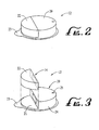
- Fig. 2 is a perspective view of a delivery device.
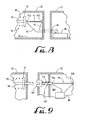
- Fig. 3 is a perspective view of a durable portion and a disposable portion of the delivery device of Fig. 2 , with the durable portion separated from the disposable portion.
- Fig. 4 is a schematic, cross-sectional view of a disposable housing portion of a delivery device.
- Fig. 5 is a side view of the disposable housing portion of the embodiment of Fig. 4 .
- Fig. 6 is a schematic, cross-sectional view of a durable housing portion of a delivery device according to an embodiment of the invention.
- Fig. 7 is a side, schematic, cross-sectional view of the durable housing portion of Fig. 6 .
- Fig. 8 shows a schematic view of a pump device and reservoir according to a further embodiment of the invention.
- Fig. 9 shows a schematic view of a pump device and reservoir according to yet a further embodiment of the invention.
- Fig. 10 shows a schematic view of a pump device and reservoir according to yet a further embodiment of the invention.
- Fig. 11 shows a side, partial cross-section view of a piston of the pump device of Fig. 8 , according to an embodiment of the invention.
- Fig. 12 shows a perspective view of a shuttle housing of the pump device of Fig. 10 , according to an embodiment of the invention..
- Figs. 13a-15b show side cross-section, views of the pump device of Fig. 10 , in a fill, shuttle and dispense position, respectively.
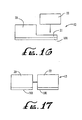
- Fig. 16 shows a schematic side view of an arrangement of a durable housing portion and a disposable housing portion of a delivery system consistent with Fig 3 .
- Fig. 17 shows a schematic side view of an arrangement of a durable housing portion and a disposable housing portion of a delivery system.
- Fig. 18 shows a partially exploded view of a delivery device.
- Fig. 19 shows a schematic top view of an arrangement of a durable housing portion and a disposable housing portion of a delivery system.
- Fig. 20 shows a schematic top view of an arrangement of a durable housing portion and a disposable housing portion of a delivery system.
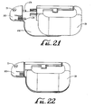
- Figs. 21-23 each show a perspective view of a connection arrangement for a disposable housing portion and an injection site module.
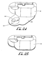
- Figs. 24 and 25 each show a perspective view of another connection arrangement for a disposable housing portion and an injection site module.
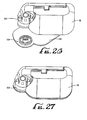
- Figs. 26-28 each show a perspective view of yet another connection arrangement for a disposable housing portion and an injection site module.
- a delivery device includes first and second housing portions (referred to herein as a durable housing portion and a disposable housing portion, respectively) that are configured to engage and attach to each other for operation.
- the disposable housing portion may contain or otherwise support an infusion medium reservoir and other components that come into contact with the infusion medium and/or the patient-user during operation.
- the disposable housing portion may also contain or otherwise support a pump device in accordance with one of the embodiments described herein.
- the pump device is connected or connectable in fluid flow communication with the reservoir, to draw fluid from the reservoir and/or convey the fluid to an injection site.
- the disposable housing portion may be disengaged and separated from the durable housing portion, such that the disposable housing portion may be readily disposed of after it has been in use for a period of time, or after one or a prescribed number of uses.
- the durable housing portion may be engaged and operatively connected to another disposable housing portion (such as a new, refurbished, user-filled, pre-filled, refilled or re-manufactured disposable housing portion) for further operation.
- the durable housing portion may contain or otherwise support components that do not come into contact with the infusion medium or the patient-user during normal operation of the delivery device, including, but not limited to, a drive device, drive linkage, electronic circuits and, in some embodiments, a power source.
- Delivery device embodiments described herein may employ any one of various pumps described herein, to draw the infusion medium from the reservoir and/or convey the infusion medium to an injection site.
- Particular pumps may be configured to provide a pump configuration that is operable in the manner described herein, yet is capable of being manufactured with sufficient economical economy to be included in a disposable housing portion.
- embodiments of the present invention are described herein with reference to an insulin delivery example for treating diabetes, other embodiments of the invention may be employed for delivering other infusion media to a patient-user for other purposes.
- further embodiments of the invention may be employed for delivering other types of drugs to treat diseases or medical conditions other than diabetes, including, but not limited to drugs for treating pain or certain types of cancers, pulmonary disorders or HIV.
- Further embodiments may be employed for delivering media other than drugs, including, but not limited to, nutritional media including nutritional supplements, dyes or other tracing media, saline or other hydration media, or the like.
- embodiments of the present invention are described herein for delivering or infusing an infusion medium to a patient-user, other embodiments may be configured to draw a medium from a patient-user.
- embodiments of the present invention refer to the housing portions of disclosed delivery devices as disposable or durable, and may be configured to allow the disposable housing portion to be disposed of and replaced in an economically efficient manner, it will be understood that, in further embodiments, the disposable housing portion embodiments described herein may be re-used and need not be disposed of. Similarly, the durable housing portion embodiments described herein may be disposed of after one or more uses, if desired.
- embodiments are configured to allow certain components (for example, those that contact the infusion medium or the patient-user during operation) to be housed in a first housing portion that may be readily disposable, while other components (for example, those that do not contact the infusion medium or the patient-user during operation and that have a replacement cost that is of a relatively significant level) may be housed in a second housing portion that may be re-used with one or more new, user-filled, pre-filled, refilled, refurbished or remanufactured disposable first housing portions.
- FIG. 1 A generalized representation of an infusion medium delivery system 10 is shown in Fig. 1 , wherein the system includes a delivery device 12.
- the system 10 may also include other components coupled for communication with the delivery device 12, including, but not limited to, a sensor or monitor 14, a command control device (CCD) 16 and a computer 18.
- CCD command control device
- Each of the CCD 16, the sensor or monitor 14, the computer 18 and the delivery device 12 may include receiver, transmitter or transceiver electronics that allow communication with other components of the system.
- the delivery device 12 may include electronics and software for analyzing sensor data and for delivering the infusion medium according to sensed data and/or pre-programmed delivery routines.
- the system 10 may include a delivery device 12 that operates without any one or more of the other components of the system 10 shown in Fig. 1 .
- Examples of the types of communications and/or control capabilities, as well as device feature sets and/or program options may be found in published U.S. Patent Application US 2003/0212364 entitled "External Infusion Device with Remote Programming, Bolus Estimator and/or Vibration Alarm Capabilities," and published U.S.
- the delivery device 12 and sensor or monitor 14 are secured to a patient-user 1.
- the locations at which those components are secured to the patient-user 1 in Fig. 1 are provided only as a representative, non-limiting example.
- the delivery device 12 and sensor or monitor 14 may be secured at other locations on the patient-user 1, and such locations may depend upon the type of treatment to be administered by the system 10.
- Such other locations may include, but are not limited to, other locations on the patient-user's body, locations on the patient-user's clothing, belt, suspenders, straps, purse, tote or other structure that may be carried by the patient-user.
- the delivery device 12 contains a reservoir of an infusion medium and a pump, for delivering the infusion medium, such as, but not limited to an insulin formulation, into the patient-user's body in a controlled manner.
- Control instructions and/or data may be communicated between the delivery device 12, the sensor or monitor 14, the CCD 16 and the computer 18.
- the delivery device 12 may be configured to secure to the skin of a patient-user 1, in the manner of a patch, at a desired location on the patient-user. In such embodiments, it is desirable that the delivery device 12 have relatively small dimensions for comfort and ability to conceal the device, for example, under a garment
- patch-like delivery devices are described in published U.S. Patent Application US 2006/0264894 .
- Delivery devices described in published U.S. Patent Application US2006/0264894 employ a reservoir structure having a moveable plunger for selectively driving fluid from the reservoir.
- An example of a patch-like delivery device 12 is shown in Figs. 2-3 herein which, according to one embodiment of the present invention, may employ a pump and drive arrangement such as shown and described with respect to Figs. 4-7 or Figs. 8 and 9 .
- Further delivery device embodiments may employ a pump and drive arrangement such as shown and described with respect to Figs. 10-15 .
- Yet further delivery device arrangements may employ a pump and drive arrangement such as shown and described with respect to Figs. 16 and 17 .
- the delivery device 12 in Fig. 2 includes a base housing portion 20 that may be disposable after one or a number of specified uses, and a further housing portion 22.
- the base portion 20 is referred to herein as a disposable housing portion or disposable portion
- the further housing portion 22 is referred to herein as a durable housing portion or durable portion.
- either or both housing portions 20 or 22 may be disposed of or re-used, depending upon the context of use.
- the disposable housing portion 20 may support structural elements that ordinarily contact the patient-user's skin or the infusion medium, during operation of the delivery device 12.
- the durable housing portion 22 may support elements (including electronics, motor components, linkage components, and the like) that do not ordinarily contact the patient-user or the infusion medium during operation of the delivery device 12.
- elements in the durable housing portion 22 of the delivery device 12 are typically not contaminated from contact with the patient-user or the infusion medium during normal operation of the delivery device 12.
- the disposable housing portion 20 of the delivery device 12 includes a base 21 that includes or otherwise supports a reservoir retaining portion 24 that houses a reservoir and a pump device.
- the durable housing portion 22 may include a housing that secures onto the base 21 adjacent the reservoir retaining portion 24.
- the durable housing portion 22 may house a suitable drive device, such as an electrically operated motor (not shown in Fig. 2 ), and drive linkage components (not shown in Fig. 2 ) for operatively coupling the drive device to the pump to drive fluid out of the reservoir, when the durable housing portion 22 is coupled to the disposable housing portion 20.
- the durable housing portion 22 also may house suitable control electronics (not shown in Fig. 2 ) for controlling the operation of the drive device to drive fluid from the reservoir in a controlled manner. Further arrangements may include other electronics within the durable housing portion 22, such as, but not limited to communication electronics (not shown in Fig. 2 ) for communicating with the sensor or monitor 14, the CCD 16, the computer 18 and/or other components of the system 10 shown in Fig. 1 .
- the base 21 of the disposable housing portion 20 has a bottom surface (facing downward and into the page in Figs. 2 and 3 ) that is configured to secure to a patient-user's skin at a desired location on the patient-user.
- a suitable adhesive may be employed at the interface between the bottom surface of the base 21 and the patient-user's skin, to adhere the base 21 to the patient-user's skin.
- the adhesive may be provided on the bottom surface of the base 21, with a peelable cover layer 23 covering the adhesive material. In this manner, a patient-user may peel off the cover layer 23 to expose the adhesive material and then place the adhesive side of the base 21 against the patient-user's skin.
- multiple layers of adhesive material alternating with multiple layers of cover layer material may be provided on the base 21, to allow the base to be secured to, removed from and then, again, secured to a patient-user's skin for multiple reuses or re-applications.
- multiple alternating layers of adhesive material and peelable covers may be employed, for multiple applications or re-applications of the base 21 to the patient-user's skin.
- the disposable portion 20 may include a button or other operator 25 for operating a needle insertion mechanism located within the reservoir retaining portion 24.
- reference number 25 may represent an opening, through which an external needle insertion mechanism may operate. Examples of suitable needle insertion mechanisms are described in published U.S. Patent Application US 2006/0264894 .
- Other needle/cannula insertion tools may be used (or modified for use) to insert a needle and/or cannula, such as for example published U.S. Patent Application US 2003/0225373 and/or published U.S.
- the reservoir retaining portion may include a suitable opening or port for connecting one end of a hollow tube to the reservoir, while the other end of the hollow tube is connected to a hollow needle for piercing the patient-user's skin and conveying the infusion medium from the reservoir into the patient-user for examples, as described with reference to Fig. 2 of published U.S. Patent Application US 2006/0264894 .
- the durable housing portion 22 of the delivery device 12 includes a housing shell configured to mate with and secure to the disposable housing portion 20.
- the durable housing portion 22 and disposable housing portion 20 may be provided with correspondingly shaped grooves, notches, tabs or other suitable features that allow the two parts to easily connect and disconnect from each other (for example, by a friction connection, snap connection, flexible or moveable interlocking members or other suitable connection arrangement), by manually pressing the two portions together in a manner well known in the mechanical arts.
- the durable housing portion 22 and disposable portion 20 may be separated from each other by manually applying sufficient force to unsnap the two parts from each other.
- a suitable seal such as an annular seal, may be placed along the peripheral edge of the disposable housing portion 20 and/or the durable housing portion 22, so as to provide a liquid, hermetic, or airtight seal between the durable portion 20 and the durable portion 22.
- the durable housing portion 22 and disposable housing portion 20 may be made of suitably rigid materials that maintain their shape, yet provide sufficient flexibility and resilience to effectively snap together and apart, as described above.
- the base 21 material may be selected for suitable compatibility with the patient-user's skin.
- the disposable housing portion 20 and the durable housing portion 22 of the delivery device 12 may be made of any suitable plastic, metal, composite material or the like.
- the disposable housing portion 20 may be made of the same type of material or a different material relative to the durable housing portion 22.
- the disposable and durable housing portions may be manufactured by injection molding or other molding processes, machining processes or combinations thereof.
- the base 21 may be made of a relatively flexible material, such as a flexible silicone, plastic, rubber, synthetic rubber or the like. By forming the base 21 of a material capable of flexing with the patient-user's skin, a greater level of patient-user comfort may be achieved when the base is secured to the patient-user's skin. Also, a flexible base 21 can result in an increase in the site options on the patient-user's body at which the base 21 may be secured.
- the disposable housing portion 20 and/or the durable housing portion 22 may include an internal sensor (not shown in Figs. 2 and 3 ) for connection to a patient-user, for example, through a needle (not shown in Figs 2 and 3 ) for piercing a patient-user's skin when the disposable housing portion 20 is secured to a patient-user's skin.
- a suitable aperture (not shown in Figs. 2 and 3 ) may be formed in the base 21, to allow the passage of the sensor needle, when the sensor needle is extended to pierce a patient-user's skin.
- the durable housing portion 20 of the delivery device 12 may be connected to an external sensor 14, through a sensor lead, as described with respect to Fig. 2 of published U.S.
- the sensor may include any suitable biological sensing device, depending upon the nature of the treatment to be administered by the delivery device 12.
- the sensor 14 may include a blood glucose sensor.
- one or more environmental sensing devices may be included in or on the delivery device 12, for sensing one or more environmental conditions.
- the sensor may be included with as a part or along side the infusion cannula and/or needle, such as for example as shown in published U.S. Patent application US 2006/0253085 entitled "Dual Insertion Set.”
- the disposable elements may be arranged on the disposable portion 20, while durable elements may be arranged within a separable durable portion 22.
- the disposable portion 20 may be separated from the durable portion 22, so that the disposable portion 20 may be disposed of in a proper manner.
- the durable portion 22 may, then, be mated with a new (un-used, user-filled, pre-filled, refilled, refurbished or re-manufactured) disposable portion 20 for further delivery operation with a patient-user.
- This also provides the user with the option to change medication delivery, by changing out and replacing reservoirs 26 with different ones containing either different medications, such as Amilyn, GLP-1, Byetta, Peptide C, insulin sensitizers, combinations of medications (with or without insulin) or the like.
- different medications such as Amilyn, GLP-1, Byetta, Peptide C, insulin sensitizers, combinations of medications (with or without insulin) or the like.
- the user my change out different types of insulin (e.g., long acting, fast acting, or the like) or utilize different concentrations (U50, U100, U200, U400 or the like).
- FIG. 4-7 An example of a disposable housing portion 20 and a durable housing portion 22 of a delivery device 12 is shown in Figs. 4-7 , wherein Figs. 4 and 5 show a top and side view, respectively, of a disposable housing portion 20, while Figs. 6 and 7 show a top and side cross-sectional view of a durable housing portion 22.
- the disposable housing portion 20 includes a base portion 21 and a reservoir retaining portion 24, as described above.
- the durable housing portion 22 is configured to be manually positioned on the base portion 21, adjacent the reservoir retaining portion 24 of the disposable housing portion 20 and to be engaged with and connected to the disposable housing portion 20, yet be selectively separable from the disposable housing portion 20, by manual force.
- a drive device within the durable housing portion 22 is arranged to make an operative connection with a pump device located within the disposable housing portion 20, as described below.
- a reservoir 26 is located in the reservoir retaining portion 24.
- the reservoir 26 may include a container having an internal volume for containing a fluidic infusion medium, such as, but not limited to an insulin formulation
- a fluidic infusion medium such as, but not limited to an insulin formulation
- the reservoir 26 may be made of any material suitably compatible with the infusion medium, including, but not limited to suitable metal, plastic, ceramic, glass, composite material or the like.
- the reservoir 26 may be formed of a plastic material referred to as TOPAS (trademark of Ticona, a subsidiary of Celanese Corporation), such as described in U.S. Patent. Publication US-A-2005/0197626 ).
- the reservoir 26 may be supported by the reservoir retaining portion 24 of the disposable housing portion 20 in any suitable manner.
- the reservoir 26 may be supported on a surface of the base 21 and held in place by one or more projections, walls or other surfaces.
- the reservoir 26 may be configured to be removable and replaceable with respect to the disposable housing portion 20.
- the reservoir 26 may be secured to the disposable housing portion 20 in a manner intended to inhibit removal of the reservoir 26 from the disposable housing portion 20.
- an adhesive material may be employed to adhere a surface of the reservoir 26 to the base 21 or other structure of the disposable housing portion 20.
- multiple layers of adhesive material may be provided on the reservoir 26 or the base 21, to allow the reservoir to be secured to, removed from and then, again, secured to the base or replaced with another reservoir to secure to the base, for reservoir replacement, refilling, or other service.
- the reservoir 26 may be formed unitarily with the reservoir retaining portion 24, for example, as a hollow chamber provided within an otherwise solid portion of the reservoir retaining portion 24.
- the hollow interior of the reservoir retaining portion 24 may be coated or lined in another manner with a suitable metal, plastic, plastic TOPAS (trademark of Ticona, a subsidiary of Celanese Corporation), ceramic, glass, composite material or the like.
- the retaining portion 24, itself may be made of a suitable metal, plastic, plastic, TOPAS (trademark of Ticona, a subsidiary of Celanese Corporation), ceramic, glass, composite material or the like.
- the reservoir 26 has an outlet port 30, through which the infusion medium contained within the interior of the reservoir 26 may be communicated out of the reservoir.
- the outlet port 30 is open to the interior of the reservoir 26 and may include suitable tube-connection structure for connecting a fluid conduit 32 in fluid flow communication with the outlet port.
- the connection structure may include any suitable connection structure that may be selectively (or, in some arrangements, permanently) connected to a reservoir 26 to provide fluid flow communication with the interior of the reservoir 26.
- the connection structure may function with a pierceable septum located within the outlet port of the reservoir.
- the connection structure may include a typical Luer-type connector having a cap structure for receiving an outlet port of the reservoir and a hollow needle for piercing the septum in the outlet port of the reservoir 26.
- the conduit 32 may include any suitable structure that provides a fluid flow path, such as, but not limited to a tube-shaped conduit made of any suitable material, including, but not limited to silicone or other plastic, metal, ceramic or composite material.
- a first end of the conduit 32 is connected or connectable to the reservoir, through a reservoir connection structure as described above.
- a second end of the conduit 32 is connected in fluid flow communication with an inlet port 33 of a pump device 34.
- the pump device 34 has an outlet port 35 connected in fluid flow communication with a second conduit 36, for conveying fluid to a delivery or injection site 38 located on the disposable housing portion 20.
- the injection site 38 may include an insertion mechanism to assist the insertion of a needle or cannula into the patient-user and connection of the needle or cannula in flow communication with the second conduit 36. Examples of such insertion mechanisms that are built into a delivery device are described in published US. Patent Application US 2006/0264894 filed 8/23/05 , titled "Infusion Device And Method With Disposable Portion".
- needle/cannula insertion tools may be used (or modified for use) to insert a needle and/or cannula; such as for example published U.S. Patent Application US 2003/0225373 filed March 14, 2003 and/or published U.S. Patent Application 2004/0002682 filed December 9, 2002 , and entitled "Insertion Device For Insertion Set and Method of Using the Same.”
- the example pump device 34 in Fig. 4 is not in accordance with the present invention. It includes a pump chamber 44 having an internal volume 45 and moveable piston having a piston head 46 located within the pump chamber 44 and a piston shaft 50 extending from the piston head.
- the piston head 46 is selectively moveable from a retracted position (as shown in Fig. 4 ) in the direction of arrow 48, to an active position, to reduce the volume of the portion of the chamber 44 on the outlet port side of the piston head 46.
- the piston head 46 is also moveable from the active position toward the direction opposite of the arrow 48, to the retracted position (as shown in Fig. 4 ), to increase the volume of the portion of the chamber 44 on the outlet port side of the piston head 46.
- the piston head 46 is fixedly connected to the piston shaft 50.
- the piston shaft 50 defines a longitudinal axis A that extends along the linear direction of movement of piston 46 (the linear direction of and opposite of the arrow 48) and has a first end that is connected to the piston head.
- the piston head 46 and the piston shaft 50 may include a unitary body. Alternatively, the piston head 46 and the piston shaft 50 may include two members that are coupled together in a fixed relation to each other.
- the second end of the piston shaft 50 is fixedly connected to a push plate 52.
- the push plate 52 and the piston shaft 50 may include a unitary body. Alternatively, the push plate 52 and the piston shaft 50 may include two members that are coupled together in a fixed relation to each other.
- the piston head 46, piston shaft 50 and push plate 52 may be made of any suitably rigid material or materials, including, but not limited to metal, plastic, ceramic, composite material or the like.
- the push plate 52 may be located within a second chamber 54 that is spaced from the piston chamber 44, but connected to the piston chamber 44 by a channel section 56.
- the channel section 56 may include a hollow, tubular structure having an internal passage through which the piston shaft 50 extends.
- One or more seals 58 may be located within or adjacent to the internal passage of the channel section 56, such as, but not limited to one or more o-ring seals or the like, for inhibiting fluid from passing through the channel section 56.
- the seal(s) 58 may be made of any suitable seal material, including, but not limited to, plastic, rubber, silicone, metal, ceramic or composite material.
- a bias member 60 is operatively connected to the piston, for example, by operative connection with the push plate 52, to provide a bias force on the piston for urging the piston along the linear dimension of the axis A, opposite to the direction of arrow 48.
- the bias member 60 includes a coil spring arranged within the second chamber 54, around and coaxial with the longitudinal axis A of the piston shaft 50.
- the coil spring bias member 60 of Fig. 4 has one end that abuts an internal wall of the second chamber 54 and a second end that abuts a first surface of the push plate 52.
- the coil spring bias member 60 is configured to be in a partially compressed state, to impart a force on the push plate 52 in the direction opposite to the direction of arrow 48.
- the first surface of the push plate 52 may include an annular groove in which one end of the coil spring bias member 60 may reside, to help retain the coil spring bias member 60 in place.
- a similar annular groove may be provided in the surface of the interior wall of the second chamber 54 that is abutted by the coil spring bias member, in which the other end of the coil spring bias member may reside.
- Each of the pump chamber 44 and the second chamber 54 may include a generally cylindrical body, having a hollow interior.
- the channel section 56 may include a generally hollow, cylindrical section extending between the pump chamber 44 and the second chamber 54 and having a generally ' cylindrical interior volume.
- Each of the piston head 46 and the push plate 52 may include disk-shaped members and the piston shaft 50 may include a cylindrical member, each having a generally circular cross-section (taken perpendicular to the axis A).
- the pump chamber 44, second chamber 54 and channel section 56 may include a single, unitary structure.
- the pump chamber 44, second chamber 54 and channel section 56 may be composed of one or more separate parts that are connected together in a fixed relation to each other.
- the pump chamber 44, second chamber 54 and channel section 56 may be made of any suitably rigid material or materials, including, but not limited to metal, plastic, ceramic, composite material or the like.
- the second chamber 54 may be configured unitarily with the housing structure that forms the reservoir retaining portion 24 of the disposable housing portion 20.
- the housing structure of the reservoir retaining portion 24 may define an interior volume (for containing the reservoir 26, conduits 32 and 36, components of the injection site 38 and components of the pump device 34) that is sealed from the external environment by the walls of the housing structure, the seal 58 and a septum or other seal structure in the delivery site 38, prior to operation of a needle injector at the injection site.
- the reservoir retaining portion 24 of the disposable housing portion 20 has a side or wall 66 that has an opening (which may be a recess) 68 through which the push plate 52 may be acted upon.
- a second surface of the push plate 52 (facing in an opposite direction relative to the facing direction of the first surface against which the coil spring bias member 60 abuts) may be exposed through the opening 68 and faces in a direction outward from the opening 68.
- the push plate is arranged to be engaged by (or otherwise acted upon) a portion of a drive linkage supported on the durable housing portion 22, upon the durable housing portion 22 and disposable housing portion 20 being engaged and connected together for operation, as described below.
- the durable housing portion 22 has a side or wall 70 ( Fig. 6 ) that faces the wall 66 of the reservoir retaining portion 24 of the disposable housing portion 20, when the durable housing portion 22 is engaged with the disposable housing portion 20 as shown in Fig. 2 .
- the side or wall 70 defines an opening 72 through which a portion of a linkage structure may extend, to contact and act upon the push plate 52, when the durable housing portion 22 is engaged with the disposable housing portion 20.
- the durable housing portion 22 is configured to engage and connect to the disposable housing portion 20, yet be disconnected and separated from the disposable housing portion 20 by application of sufficient manual force.
- Any suitable connection structure including, but not limited to, engagable snap fitted members, friction fitted members, flexible or moveable interlocking members or the like may be employed on the disposable housing portion and durable housing portion.
- the connection structure includes a pair of engagement pawls 74 extending from the wall 66 of the reservoir retaining portion 24 of the disposable housing portion 20 and a pair of correspondingly shaped receptacles 76 on the wall 70 of the durable housing portion 22.
- Each engagement pawl 74 is configured to fit within an associated one of the receptacles 76, when the durable housing portion 22 is aligned with the disposable housing portion 20 in an engagement position, to connect the durable housing portion 22 and the disposable housing portion 20 together.
- Each engagement pawl 74 may include a structure extending from the wall 66 and having a stop surface 78 for engaging a corresponding stop surface 79 of a receptacle 76, when the engagement pawl 74 is inserted into its associated receptacle 76.
- the stop surfaces 78 and 79 when engaged, inhibit separation of the durable housing portion 22 and the disposable housing portion 20, unless a sufficient separation force is applied.
- the relative flexibility and resiliency of the pawls 74 and/or receptacles 76 allow the durable housing portion 22 and the disposable housing portion 20 to remain connected to each other unless a sufficient manual force is applied in the separation directions (for example the disposable housing portion is forced in a direction of arrow 48 relative to the durable housing portion and/or the durable housing portion is forced in a direction opposite to arrow 48 relative to the disposable housing portion).
- a sufficient force would cause the pawls 74 and/or receptacles 76 to resiliently flex enough to allow the stop surface 78 of each pawl 74 to ride over the stop surface 79 of its associated receptacle and, thus, allow the pawls 74 to be withdrawn from the receptacles 76, as the disposable portion 20 is separated from the durable portion 22.
- Each pawl 74 may include an angled or curved surface (surface at an angle of having a tangent that is not parallel or perpendicular to external surface of the wall 66) to facilitate insertion of the pawls 74 into the receptacles 76.
- the pawls 74 may be made of a material having sufficient rigidity and flexibility to function as described herein, including, but not limited to, metal, plastic, composite material or the like.
- the pawls 74 may be made of the same material as and may be formed unitary with the wall 66 of the disposable housing portion 22. In other arrangements, the pawls 74 may be formed separately from the disposable housing portion and then connected to the wall 66.
- While the illustrated embodiment shows a pair of pawls 74 and a corresponding pair of receptacles 76, other embodiments may employ a single pawl and associated receptacle or more than two pawls and associated receptacles.
- the illustrated arrangement shows pawls 74 on the wall 66 of the disposable housing portion 20 and receptacles 76 on the wall 70 of the durable housing portion 22, other embodiments may employ one more pawls on the wall 70 of the durable housing portion 22 and one or more associated receptacles on the wall 66 of the disposable housing portion 20.
- Yet other arrangements may employ various combinations of one or more pawls and associated receptacles on each of the walls 66 and 70.
- the durable housing portion 22 includes a housing structure having an interior volume 80.
- a drive device 82 is supported in interior volume of the durable housing portion 22 and is operatively connected to a drive shaft 84, through a linkage structure 86.
- the drive device 82 may include, for example, but is not limited to a motor or other device for converting electrical power into rotational motion.
- Such drive devices may include, but are not limited to, a DC motor, a flat or pancake DC motor, a servo motor, a stepper motor, an electronically commutated motor, a rotary piezo-electrically actuated motor, a piezo-electrically actuated or thermally actuated bender with or without an escapement wheel, an electronically actuated solenoid with or without an escapement wheel or a shaped memory alloy wire with or without an escapement wheel.
- escapement wheel arrangements with benders, solenoids, shaped memory alloy wires or the like Further examples of shape memory alloy wire drive systems may be found in U.S. Patent No. 6,375,638 issued April 23, 2002 , and entitled "Incremental Motion Pump Mechanisms Driven by Shape Memory Alloy Wire or the Like.”
- the linkage structure 86 may include any suitable gear, gear train, belt, shaft or other linkage arrangement that communicates rotational motion of the motor or other rotational motion producing device to linear motion of the drive shaft 84.
- the linkage structure includes a drive cam 90 that is coupled for rotation with a drive gear 92, about a rotational axis 94.
- the drive shaft 84 has one end coupled to the drive cam, at a location offset from the rotational axis 94, such that rotation of the drive cam results in linear motion of the drive shaft 84.
- the drive gear 92 is arranged to be rotationally driven about the axis 94 by the motor or other rotational drive device, for example, by direct connection to the motor or other rotational drive device or by indirect connection through other portions of the linkage structure 86, such as, but not limited to gears, shafts, belts or the like.
- linkage structures may be found in published U.S. Patent Application US 2001/0041869 filed March 21, 2001 , and entitled "Control Tabs For Infusion Devices And Methods Of Using The Same".
- the drive device 82 may include a device that converts electrical power to linear motion, including, but not limited to piezo-electrically actuated solenoid or bender, thermally actuated solenoid or bender and electrically actuated solenoid devices.
- the linkage structure 86 may include any suitable gear, gear train, belt, shaft or other linkage arrangement that communicates linear motion of the drive device to linear motion of the drive shaft 84.
- the linear motion drive device may be directly connected to the drive shaft 84 (or the drive shaft 84 may be part of the linear motion drive device, such as the drive shaft of a solenoid).
- the drive device 82 is connected to a control circuit that is supported within the durable housing portion 22 of the delivery device, for controlling the operation of the drive device according to a desired infusion delivery program or profile.
- a delivery program or profile may be stored within a suitable electronic storage medium (not shown) located within the durable housing portion 22 and/or may be communicated to the delivery device 12 from other sources, such as a CCD 16 or a computer 18 (as shown in Fig. 1 ).
- the delivery program or profile may be employed by the control circuit to control the operation of the drive device 82 in accordance with the delivery program or profile.
- control circuit may control the drive device 82 to deliver one or more discrete volumes of the infusion medium in response to delivery demand control signals generated within the device 12 or communicated to the device 12 from other sources, such as a CCD 16 or a computer 18 (as shown in Fig. 1 ).
- the durable housing portion 22 may contain additional electronic circuitry (not shown) for communication with external devices such as the CCD 16 or computer 18, for storage of sensor data or other data, for processing and control functions, or for other functions.
- the durable housing portion 22 may have a user interface (not shown) including one or more buttons, electronic display, or the like, and associated electronic interface circuitry to allow a user to access data and/or input data or instructions to control electronic circuitry within the durable housing portion 22. Examples of the types of communications and/or control capabilities, as well as device feature sets and/or program options may be found in published U.S. Patent Application US 2003/0212364 filed May 27, 2003 , and entitled “External Infusion Device with Remote Programming, Bolus Estimator and/or Vibration Alarm Capabilities," and published U.S. Patent Application US 2004/0073095 filed May 5, 2003 , and entitled “Handheld Personal Data Assistant (PDA) with a Medical Device and Method of Using the Same.”
- PDA Personal Data Assistant
- the durable housing portion 22 may contain a battery, high energy capacitor or other electronic power source for providing electrical power to the drive device 82, control circuit electronics and other electronic circuitry contained in the durable housing portion 22.
- the control circuit electronics, other electronic circuitry and the power source are represented in Figs. 6 and 7 by reference number 98.
- the battery, high energy capacitor or other electronic power source may be rechargeable through a recharge connector (not shown) provided on the durable housing portion 22.
- the power source may be removable and replaceable with respect to the durable housing portion 22.
- a battery, capacitor or other electronic power source (not shown) may be supported on the disposable housing portion 20 and connectable to the drive device 82, control circuit and other electronic circuitry in the durable housing portion, through electrical connectors (not shown in Figs.
- Such electrical connectors may include one or more pairs of conductive pads, where each pair of pads is connected to opposite poles of the power source and located on any suitable surface of the disposable housing portion 20 that engages a corresponding surface on the durable housing portion 22, when the durable housing portion 22 is engaged with the disposable housing portion 20.
- the corresponding surface of the durable housing portion 22 includes one or more corresponding pairs of conductive pads that are electrically connected to the drive device 82, control circuit and other electronic circuitry in the durable housing portion and are arranged to engage the conductive pads on the disposable housing portion, when the durable housing portion 22 is coupled to the disposable housing portion 20.
- the drive device 82, linkage structure 86, control circuit, other electronic circuitry and power source 98 described above, are located within the interior volume 80 of the durable housing portion 22.
- the drive shaft 84 extends through an opening in the wall 70 of the durable housing portion 22.
- the interior volume 80 of the durable portion 22 may be suitably sealed from the external environment by the housing structure that forms the durable portion 22 and by one or more seals 99 provided around the drive shaft 84, within or adjacent the opening in the wall 70.
- the seal(s) 99 may include, but are not limited to, one or more o-ring seals or the like.
- the seal(s) 99 may be made of any suitable seal material, including, but not limited to, plastic, rubber, silicone, metal, ceramic or composite material.
- the delivery device 12 of Figs. 4-6 includes a disposable housing portion 20 supporting a reservoir 26, a pump device 34 and other components described above, and a durable housing portion 22 for supporting a drive device 82, a drive shaft 84, linkage structure 86, and electronics (which may also include a power source) 98.
- the reservoir in the disposable housing portion 20 may be filled with a suitable infusion medium.
- the disposable housing portion 20 may be secured to a patient-user's skin (either before or after filling the reservoir), in the manner described above.
- a needle injector may be operated to place a hollow needle or cannula through the patient-user's skin and connect the hollow needle or cannula in fluid flow communication with the conduit 36.
- the durable housing portion 22 may be manually aligned with the disposable housing portion 20, and engaged with and connected to the disposable housing portion 20 (either before or after the disposable housing portion is secured to a patient-user's skin and either before or after the needle injector is activated), in the manner described above.
- an end of the drive shaft 84 (opposite to the end connected to the drive cam 90) abuts or is positioned adjacent to the push plate 52.
- the drive shaft 84 may extend into the opening in the wall 66 of the reservoir retaining portion 24 of the disposable housing portion 20 and contact or reside adjacent the outward-facing surface of the push plate 52.
- the drive device 82 may be selectively activated, with the electrical control and power provided by the control circuit electronics and power source 98, to selectively move the drive shaft 84 in a back-and-forth motion along two generally linear directions (corresponding to the direction of arrow 48 and the direction opposite to the direction of arrow 48), as described above.
- the drive device 82 may be controlled to selectively rotate the drive gear 92 and drive cam 90 in a first direction about the rotation axis 94. As the drive cam 90 rotates, the drive shaft is moved in one direction and then the opposite direction, along the linear dimension of the arrow 48.
- the drive shaft 82 may be driven in a linear back-and-forth motion by rotating the drive gear 92 and drive cam 90 in one direction and then the opposite direction, for example, by controlling the drive device to drive in one direction and then the opposite direction.
- the extended end of the drive shaft 84 engages the push plate 52 and imparts a force on the push plate 52 in the direction of arrow 48 sufficient to move the push plate 52 in the direction of arrow 48, against the force of the coil spring bias member 60.
- the piston shaft 50 and piston head 46 are moved in the direction of arrow 48, from the retracted position (as shown in Fig. 4 ), to an active position.
- the piston head 46 moves toward the active position, the volume of the portion of the piston chamber 44 located on one side of the piston head 46 (the side to the left of the piston head 46 in the orientation shown in Fig. 4 ) is reduced. As that portion of the piston chamber 44 volume reduces, the pressure within that volume increases to force fluid through the outlet port 35, conduit 36 and one-way valve 42, to the injection site 38.
- the amount of motion of the drive shaft 84 in the direction of arrow 48 is selected to move the piston head from the retracted position (shown in Fig. 4 ). Once the piston head 46 reaches its active position, the drive shaft 84 also reaches its farthest point of motion in the direction of arrow 48. Thereafter, the drive shaft 84 is moved in the direction opposite to the direction of arrow 48 as the drive device 82 continues to impart a drive force. As the drive shaft 84 moves in the direction opposite to the direction of arrow 48, the push plate 52, piston, piston shaft 50 and piston head 46 also move in the direction opposite to the direction of arrow 48 to the retracted position (shown in Fig. 4 ), by the force of the coil spring bias member 60.
- the volume of the portion of the piston chamber 44 located on one side of the piston head 46 increases.
- the pressure within that volume decreases sufficiently to draw fluid from the reservoir 26, through the conduit 32, the one-way valve 40 and the inlet port 33, and into that portion of the volume of the piston chamber 44. In this manner, the portion of the volume of the piston chamber on one side of the piston head 46 (the side to the left of the piston head 46 in the orientation shown in Fig.
- the pump device 34 may be driven by the motion of the drive shaft 84, to effectively force infusion medium from the piston chamber 44 to the injection site 38, and by the return force of the bias member 60, to draw infusion medium from the reservoir 26, into the piston chamber 44.
- the drive device 82 may be controlled by the control circuit, in accordance with a pre-defined delivery profile, to selectively deliver a suitable amount of infusion medium to the patient-user, through the injection site.
- the delivery profile may be designed in accordance with a pre-known volume of the piston chamber 44 and the pre-known volume of infusion medium delivered through the outlet port 35 and conduit 36 to the injection site 38, for each stroke of the piston head 46 from the retracted position to the active position.
- the piston chamber 44 Before starting a pumping process, the piston chamber 44 may be primed, for example, by pre-filling the piston chamber 44 with infusion medium during manufacture, assembly or at another time period prior to securing the disposable portion of the delivery device to a patient-user's skin, by filling the piston chamber 44 either before or after securing to the patient-user through a filling port (not shown), or by operating the drive device to cause the piston head 36 to make one or more strokes to lower the pressure within the piston chamber sufficient to draw fluid from the reservoir through the inlet port 33 before activation of a needle injector at the injection site 38.
- a priming port may be provided in the piston chamber 44, where the priming port may include a one-way air valve (not shown) that allows air to escape, but inhibits infusion fluid from escaping the piston chamber 44 and inhibits air from entering the piston chamber 44.
- the priming port may be covered with a material that allows the passage of air, but inhibits the passage of water or other liquids. Examples of structures that permit air-flow, but that inhibit fluids can be found in published U.S. Patent Application US 2003/0125672 filedDecember 22, 2003 , and entitled “Reservoir Connector," and published U.S. Patent Application Serial US 2004/0092873 filed October 31, 2003 , and entitled "External Infusion Device with a Vented Housing.”
- the embodiment shown in Figs. 4-6 employs a bias member 60 for imparting a force on the push plate 52, to return push plate 52 to the retracted position (shown in Fig. 4 ).
- the drive shaft 84 may be arranged to engage and abut the push plate 52 to push the push plate 52 in the direction of arrow 48, while the bias member 60 urges the push plate 52 back toward the retracted position (in the direction opposite to the direction of arrow 48), when the drive shaft 84 is driven to the return position.
- Others arrangements may employ the return motion of the drive shaft 84 (in the direction opposite to the direction of arrow 48) to return the push plate 52 to the retracted position.
- connection structure for allowing the drive shaft 84 to be selectively engaged and connected to the push plate 52, when the durable housing portion 22 is engaged and connected to the disposable housing portion 20.
- connection structure may include, but not limited to, engageable snap fitted members, friction fitted members, flexible or moveable interlocking members or the like.
- the connection structure for connecting the drive shaft 84 to the push plate 52 may include a pawl and associated receptacle arrangement (similar to the pawl 74 and receptacle 76 described above), wherein one of the pawl and receptacle is provided on the push plate and the other of the pawl and receptacle is provided on the end of the drive shaft 84.
- the arrangement shown in Figs. 4-6 may employ any one of various types of suitable drive devices including, but are not limited to, a DC motor, a flat or pancake DC motor, a servo motor, a stepper motor, an electronically commutated motor, a rotary piezo-electrically actuated motor, a piezo-electrically actuated or thermally actuated bender with or without an escapement wheel, an electronically actuated solenoid with or without an escapement wheel or a Shape Memory Alloy (SMA) wire with or without an escapement wheel.
- a DC motor a flat or pancake DC motor
- a servo motor a stepper motor
- an electronically commutated motor a rotary piezo-electrically actuated motor
- a piezo-electrically actuated or thermally actuated bender with or without an escapement wheel
- an electronically actuated solenoid with or without an escapement wheel or a Shape Memory Alloy (SMA) wire with or without an escapement
- the linear motion of the push plate 52 may be provided by an SMA wire, such as, but not limited to, Nitinol (Nickel-Titanium/Naval Ordinance Laboratory).
- a Nitinol driver may be provided in the durable housing portion 22 or the disposable housing portion 20.
- an SMA wire 91 is located in the disposable housing portion 20, and has one end 91 a connected to the push plate 52 (or directly to the piston shaft 50 by omitting the push plate 52) and a second end 91b connected in a fixed position relative to the disposable housing portion.
- the SMA wire 91 is configured to expand in the linear direction (the direction of the wire, to push the piston shaft 50 in the direction of arrow 48, upon application of a suitable electrical potential across the SMA wire.
- the two ends 91a and 91b of the SMA wire 91 are connected, through suitable electrical leads 95 and 97, to an electrical connector element 93 on the disposable housing portion 20.
- the connector element 93 is configured to electrically connect with a corresponding connector element 93' on the durable housing portion 22, when the disposable housing portion 20 and the durable housing portion 22 are engaged.
- the connector element 93' is electrically connected to a battery (or other suitable source of electrical power) and control electronics 98, to selectively provide an electrical potential across the leads 95 and 97, to selectively energize the SMA wire, when the disposable housing portion 20 and the durable housing portion 22 are engaged. Because the power source in the durable housing portion 22 and the SMA wire drive device in the disposable housing portion 20 need only an electrical connection for operation, the respective housing portions 20 and 22 may be enclosed and sealed and need not include any openings to the external environment. In further arrangements, such sealed housing portions may include a vent opening for equalizing pressure between the interior of the housing portion and the exterior environment.
- FIG. 9 Another drive example that employs an SMA wire is shown in Fig. 9 , wherein an SMA wire is located in the durable housing portion 22.
- the SMA wire 91' has one end 91 a' coupled to a push rod 100 and a second end 91b' coupled in a fixed relation with the durable housing portion 22.
- the push rod 100 is supported for movement in a linear direction (the directions of arrow 48 and opposite to arrow 48), for example, by a suitable support structure 102 that includes a slide bearing surface abutting the push rod 100.
- the support structure 102 may be part of or affixed to the durable housing portion 22.
- the push rod 100 is connected to a mating member 104 that has a mating surface accessible from outside of the durable housing portion 22.
- a bias member provides a return force on the mating member 104 and may comprise a coil spring connected between the mating member 104 and the support structure 102.
- the mating member 104 may be located external to the durable housing portion 22 and/or may extend through an opening in the durable housing portion 22, such that the mating surface of the mating member 104 is arranged to engage a corresponding mating surface on the pump device 34, when the durable housing portion 22 and the disposable housing portion 20 are engaged.
- a connection shaft 50' extends from the pump device 34 and has a mating surface on one end that is shaped to engage and mate with the mating surface of the mating member 104.
- the connection shaft 50' extends from the push plate 52.
- the push plate 52 may be omitted, such that the connection shaft 50' comprises a portion of the piston shaft 50.
- a linear-motion pump device 134 according to an embodiment of the invention is shown in Figs. 10-15 .
- the pump device 134 may be employed in a delivery device 12 as described above with respect to Figs. 4-7 , in place of the linear motion pump device 34 described above.
- the pump device 134 includes a shuttle mechanism that is operated by imparting a linear force for providing a linear motion of a piston shuttle.
- the pump device 134 operates to dispense fluid from a reservoir 126.
- the reservoir 126 may be located in a disposable housing portion, similar to the disposable housing portion 20 described above.
- the reservoir 126 may include a reservoir structure as described above with respect to reservoir 26 in Figs. 4-7 .
- the reservoir 126 may include a flexible bag or a container having flexible walls that collapse, as fluid is withdrawn from the reservoir interior.
- the reservoir 126 may include a septum 128, such as a self-sealing septum that may be pierced by a needle (for example a syringe needle) for filling or refilling of the reservoir.
- the septum 128 may be positioned at a location where it is exposed through an opening in the housing structure that forms the disposable housing portion 20, to allow access for filling or refilling operations from outside of the disposable housing portion 20.
- the reservoir 126 may be filled or refilled, for example, by inserting a needle of a syringe through the septum 128 and operating the syringe to dispense infusion fluid from the needle, into the interior of the reservoir.
- the pump device 134 includes a shuttle housing 136 and a shuttle piston 138.
- the shuttle housing 136 includes a structural body made of any suitably rigid material, including, but not limited to, metal, plastic, ceramic, glass or composite materials.
- the shuttle housing 136 includes an interior channel 140 having a longitudinal axis A 1 .
- the shuttle housing 136 may include a cylindrical-shaped body having an outer peripheral wall surface 137 and the channel 140 may be cylindrical shaped channel generally centrally located within the cylindrical shaped body. However, other embodiments may employ other suitable shapes for the shuttle housing 136 and channel 140.
- the shuttle housing 136 includes an inlet port 142, comprising an opening through the outer wall of the shuttle housing 136, to the channel 140.
- the shuttle housing 136 also includes an outlet port 144, comprising a second opening through the outer wall of the shuttle housing 136, to the channel 140.
- the outlet port 144 is located at a spaced relation relative to the inlet port 142, along the longitudinal axis A 1 of the channel 140.
- the inlet port 142 and the outlet port 144 are offset from each other by 180 degrees around the longitudinal axis A 1 of the channel 140, with the inlet port 142 directed upward and the outlet port directed downward relative to the orientation of Figs. 10-15 .
- the inlet port 142 and the outlet port 144 may be offset from each other by less than or greater than 180 degrees, or may be in line (not offset) with respect to the longitudinal axis A 1 of the channel 140.
- the outlet port 144 may be connected to a conduit in fluid flow communication with an injection site, such as conduit 36 and injection site 38 as shown in Fig. 4 .
- the piston 138 includes first and second piston sections 146 and 148, respectively.
- Each piston section 146, 148 includes a structural body having a longitudinal axis and a shape corresponding to the shape of the channel 140. Accordingly, in embodiments in which the channel 140 has a cylindrical shape, the structural body of the piston sections 146 and 148 each include a cylindrical shaped body having an outer diameter slightly less than the diameter of the channel 140. The diameters of the piston sections 146, 148 and the channel 140 are selected to allow the piston sections 146, 148 to fit within and move axially within the channel 140, yet inhibit leakage of infusion fluid between the piston sections 146, 148 and the interior wall of the channel 140.
- the piston sections 146, 148 may be made of any suitably rigid material, including, but not limited to, metal, plastic, ceramic, glass or composite materials.
- the piston sections 146, 148 are arranged, end-to-end, at least partially within the channel 140, such that one end 147 of piston section 146 faces an opposite-facing end 149 of piston section 148.
- the piston sections 146, 148 are separate structural bodies that are coupled together, yet moveable relative to each other in the axial dimension of the channel 140.
- a coupling structure suitable for allowing axial movement of the piston sections 146 and 148 relative to each other is provided to couple the piston sections 146, 148 together.
- One embodiment of such a suitable coupling structure is shown in Fig. 11 and includes a hollow interior channel 150 extending axially within the interior of one of the piston sections, such as the piston section 148.
- the end of the piston section 148 that faces the piston section 146 is provided with an opening 152 into the interior channel 150 of the piston section 148.
- the channel 150 of the piston section 148 has a stepped interior surface, that has a first diameter D 1 adjacent the opening 152 and a second diameter D 2 further spaced from the opening 152 along the axial dimension A 1 .
- a step, forming a stop surface 154, is provided at the transition between the two diameters D 1 and D 2 of the channel 150.
- the coupling structure further includes an extension portion 156, extending axially from the end of the piston section 146 that faces the piston section 148.
- the extension portion 156 is rigidly fixed relative to the piston section 146.
- the extension portion 156 may be formed integral with the piston section 146 as a single, unitary body, or may be formed separate from the piston section 146 and fixedly secured to the piston section 146.
- the extension portion 156 extends toward the piston section 148 and through the opening 152 in the end of the piston section 148 and into the channel 150.
- the extension portion 156 has a free end on which a head 158 is located.
- the head 158 provides a stop surface 160 for engaging the stop surface 154, as described below.
- One or more seals 159 may be provided around the opening 152 and/or around the extension portion 156, to inhibit fluid flow communication through the opening 152 and into the channel 150.
- Such seal(s) 159 may be made of any suitable seal material, including, but not limited to, metal, plastic, silicone, ceramic, composite material or the like. While the coupling structure in the embodiment of Fig. 11 employs a channel 150 in the piston section 148 and an extension portion 156 on the piston section 146, other embodiments may employ a channel 150 in the piston section 146 and an extension portion on the piston section 148, to function in a manner as described herein.
- the coupling structure allows the piston sections 146, 148 to move axially relative to each other to separate from each other for a limited distance, while remaining connected to each other.
- a gap or chamber 162 is formed between the two facing ends 147 and 149 of the piston sections 146 and 148, respectively.
- the width of the gap or chamber 162 increases, as one or both of the piston sections 146, 148 move to separate, until the stop surface 160 of the head 158 engages the stop surface 154 of the stepped interior surface of the channel 150.
- the piston 138 (including both piston sections 146, 148) is moved in a linear manner, along the axial dimension A 1 , by selective operation of a drive device, similar to the operation of the drive device described above with respect to Figs. 4-7 .
- the end 151 of the piston section 148 opposite to the end 149 is arranged to be acted upon by a drive shaft, such as drive shaft 84 described above with respect to Figs. 4-7 , to impart a force on the piston section 148 sufficient to provide axial motion of the piston 138 within the channel 140.
- the shuttle housing 136 and piston 138 of the pump device 134 of Fig. 10 may be supported within the reservoir retaining portion 24 of the disposable housing portion 20 (of Figs.
- the drive shaft 84 and the end 151 of the piston section 148 may be provided with a suitable connection structure for allowing the drive shaft 84 to be selectively engaged and connected to the end 151 of the piston section 148, when the durable housing portion 22 is engaged and connected to the disposable housing portion 20.
- connection structure may include, but is not limited to, engageable snap fitted members, friction fitted members, flexible or moveable interlocking members or the like.
- connection structure for connecting the drive shaft 84 to the end 151 of the piston section 148 may include a pawl and associated receptacle arrangement (similar to the pawl 74 and receptacle 76 described above), wherein one of the pawl and receptacle is provided on the push plate and the other of the pawl and receptacle is provided on the end of the drive shaft 84.
- the drive shaft 84 may impart forces on the piston section 148 in the direction of arrow 164 and, then in the direction of arrow 166, to provide a back-and-forth motion of the piston section 148 in the axial dimension A 1 .
- the length of motion of the drive shaft 84 and the dimensions of the piston sections 146, 148 and the extensions portion 156 are selected to allow the piston sections to move (with the motion of the drive shaft 84), as described with reference to Figs. 13-15 .
- the piston 138 (including piston sections 146, 148 shown in Figs. 13-15 ) are moveable along the axial dimension A 1 , between at least three general positional locations along the axial dimension A 1 .
- the three general positional locations are referred to herein as the fill position (Figs. 13a-c), the shuttle position ( Fig. 14 ) and the dispense position (Figs. 15a-b).
- the piston 138 may be placed in a start portion of the fill position ( Fig. 13a ) prior to the beginning of operation (for example, during manufacture, assembly or installation). Alternatively, the piston 138 may be in another initial position (for example the position shown in Fig. 14 ) prior to operation, and the drive device 82 may be initially operated to move the drive shaft 84 and, thus the piston 138 from that initial position, in the direction of arrow 164, to a start portion of the fill position (as shown in Fig. 13a ).
- the drive force on the piston 138 is applied by the drive shaft 84 onto the end 151 of the piston section 148. Accordingly, if the piston sections 146, 148 are initially separated, the drive force imparted by the drive shaft 84 on the piston end 151 in the direction of arrow 164, will first cause the piston section 148 to move toward the piston section 146 and close the gap or chamber 162, until the end surfaces 147 and 149 of the piston sections 146 and 148, respectively, come into contact.
- the piston 138 In a starting (or ending) portion of the fill position, as shown in Fig. 13a , the piston 138 is arranged with the end faces 147 and 149 of the piston sections 146 and 148 adjacent the inlet port 144 and with no (or a minimal) gap between the end faces 147 and 149 of the piston sections 146 and 148. From the starting portion of the fill position of Fig. 13a , the piston section 148 may be moved in the direction of arrow 166 to open the gap or chamber 162 between the end faces 147 and 149 of the piston section.
- the low pressure volume within the gap or chamber 162 provides a sufficient pressure differential relative to the pressure within the reservoir 126, to cause fluid to flow into the gap or chamber 162, from the reservoir 126, through the inlet port 142.
- fluid is drawn from the reservoir, through the inlet port 142 and into the gap or chamber 162.
- the gap or chamber 162 continues to widen to the complete fill portion of the fill position, shown in Fig. 13c , at which the piston sections 146 and 148 are in a fully separated state (wherein the stop surfaces 154 and 160 of Fig. 11 are abutted together).
- the piston sections 146 and 148 are positioned relative to the shuttle housing 136, such that the gap or chamber 162 is located in fluid flow communication with the inlet port 144 of the shuttle housing 136. In that position, fluid flow communication is provided between the interior of the reservoir 126 and the gap or chamber 162, through the inlet port 144, to allow infusion fluid to flow from the reservoir, into the gap or chamber 162. Fluid may flow from the reservoir 126 and into the gap or chamber 162, for example, by the force of a pressure differential created when piston sections 146, 148 separate to form the gap or chamber 162 and/or by gravitational force (wherein the gap or chamber 162 is located below the reservoir 126, during operation, as shown in Figs.
- fluid flow from the reservoir 126, to the gap or chamber 162 may be provided or enhanced by providing the interior of the reservoir 126 with a pressure higher than the pressure in the gap or chamber 162 (for example, by imparting a force on a flexible wall of the reservoir and/or filling the reservoir with pressurized fluid).
- the full stroke of motion of the drive shaft 84 in the direction of arrow 166 may be selected such that the end of the stroke of motion of the drive shaft 84 in the direction of arrow 166 corresponds to the position of the piston sections 146 and 148 in Fig. 14 .
- the full stroke of motion of the drive shaft 84 in the direction of arrow 164 may be selected such that the end of the stroke of motion of the drive shaft 84 in the direction of arrow 164 corresponds to the position of the piston sections 146 and 148 in Fig. 13a .
- the drive shaft 84 begins to move back, in the direction of arrow 164 (opposite to the direction of arrow 166).
- the piston section 148 is moved in the direction of arrow 164 relative to the piston section 146 and the shuttle housing 136, as shown in Fig. 15a , to begin dispensing fluid from the gap or chamber 162, into the outlet port 144.
- the pressure in the gap or chamber 162 is increased by driving the piston sections 146 and 148 further together, to force the infusion medium out of the gap or chamber 162 and into the conduit 36.
- the drive shaft 84 may impart a force on the end surface 151 of the piston portion 148, in the direction of arrow 164 (Figs. 15a-b).
- That force causes the piston section 148 to move axially in the direction of arrow 164, relative to the piston section 146 and shuttle housing 136, until the end walls 147 and 149 ( Fig. 11 ) of the piston sections 146, 148 abut each other.
- the piston section 148 moves toward the piston section 146, the volume of the gap or chamber 162 decreases, causing the infusion medium within the gap or chamber to be forced out of the gap or chamber and be dispensed into the conduit 36, through the outlet port 144.
- the piston section 146 may be configured to provide a bi-directional friction with the interior surface of the piston channel 140 of the cylinder 136 that is greater than that of the piston member 148 in the cylinder 136.
- the piston section 146 In the fill stroke direction 166, the piston section 146 is held back relative to the motion of the piston member 148, to open the chamber 162.
- the piston section 146 In the dispense stroke direction 164, the piston section 146 resists motion relative to the motion of the piston section 148 to fully force the fluid from the chamber into the outlet port 144.
- This bi-directional friction for the piston section 146 may be provided by selecting the shape and/or size of the outer diameter of the piston section 146, or by providing a spring-loaded or otherwise biased member to bear against the piston section 146, to provide suitable friction engagement with the inside surface of the piston channel 140 and/or by providing one or more 0-ring seals around the piston section 146.
- a reservoir 126, piston 138 and shuttle housing 136 configuration may be employed in a disposable housing portion 20, as described above, in place of the pump device 34 and reservoir 26 described above with respect to Figs. 4-7 ).
- the piston 138 may be operatively coupled to a drive shaft 84, as described above, when a durable housing portion 22 is coupled to the disposable housing portion 2, to control movement of the piston 138 in a back-and-forth motion along the axial dimension A 1 (in the directions of arrows 164 and 166).
- Figs. 10-15 such movement of the piston 138 causes the piston sections 146, 148 to move between the fill position ( Fig. 11 ), the shuttle position ( Fig. 12 ) and the dispense position ( Fig. 13 ) and back, within the shuttle housing 136.
- Such motion of the piston sections 146, 148 causes a volume of infusion medium to be dispensed from the outlet port 144 and into the conduit 136, with each back-and-forth motion of the piston 138.
- the volume of infusion medium dispensed with each back-and-forth motion of the piston 138 is dependent on the volume of the gap or chamber 162 and may be pre-determined for providing a suitable delivery profile to control the operation of the drive device 84.
- the pump device embodiment of Figs. 10-15 may be operatively coupled to a linearly driven drive shaft, to allow for a controlled dispensing of infusion medium, with relatively few moving parts and relatively uncomplicated structural components.
- the disposable housing portion (e.g., 20 in Fig. 3 ) is provided with a base portion 21 that may be secured to the patient-user's skin by, for example, but not limited to, an adhesive material provided on the bottom surface of the base portion 21.
- That arrangement is generally represented, in side view, in Fig. 16 , wherein an adhesive material 101 is provided on the bottom surface (skin-facing surface) of the base 21 of the disposable housing portion 20.
- the durable housing portion 22 may be configure to be arranged on the base 21 of the disposable housing portion 20 to engage and connect to the disposable housing portion 20.
- the base 21 may be disposed between the durable housing portion 22 and the patient-user's skin, during operation, such that only the base 21 of the disposable housing portion remains in contact with the patient-user's skin, during operation.
- the durable housing portion 22 and the disposable housing portion 20 may be configured to engage each other in a side-by-side arrangement, for example, as represented in Fig. 17 .
- a side-by-side arrangement in Fig. 17 either one or both of the durable housing portion 22 and the disposable housing portion 20 may be provided with a base having an adhesive material 101 (and a peelable cover layer 23 as shown in Fig. 3 ).
- one or both of the durable housing portion 22 and the disposable housing portion 20 may be attachable and detachable from a separate base member 21'.
- Suitable connecting structure such as described above for connecting the durable housing portion and the disposable housing portion together, may be employed for connecting the durable housing portion and the disposable housing portion to the base member 21'.
- the separate base member 21' may include a generally flat, plate-like structure made of any suitably rigid material including, but not limited to, plastic, metal, ceramic, composite material or the like.
- the base member 21' has a surface (the upper-facing surface in Fig. 18 ) to which the disposable housing portion 20 and the durable housing portion 22 may be attached.
- the base member 21' has a second surface (the lower-facing surface in Fig. 18 ) to which an adhesive material and a peelable cover film may be applied, as described above, to allow the base member 21' to be secured to a patient-user's skin.
- the base member 21' may include a needle inserter device 25, as described above.
- the base member 21' may be secured to a patient-user's skin.
- the needle inserter 25 may be activated to insert a hollow needle or cannula into the patient-user's skin.
- the durable housing portion 22 and the disposable housing portion 20 may be attached to the base member 21', to connect the reservoir within the disposable housing portion 20 in fluid flow communication with the hollow needle or cannula.
- the durable housing portion 22 and the disposable housing portion 20 may be connected together (for example, in the manner described above) before attaching those housing portions to the base member 21'.
- one of the durable and disposable housing portion is attached to the base member 21' before the durable and disposable housing portions are connected together.
- the needle inserter device may be activated to insert a hollow needle or cannula into the patient-user's skin after the disposable housing portion is attached to the base member 21' (either before or after the durable and disposable housing portions are connected together).
- Other needle/cannula insertion tools may be used (or modified for use) to insert a needle and/or cannula, such as for example published U.S. Patent Applications US 2003/0225373 and/or published U.S. Patent Application US 2004/0002682 entitled "Insertion Device For Insertion Set and Method of Using the Same.”
- reference number 25 may represent an opening in the base member 21' that aligns with a needle inserter device (or aligns with a further opening) located in the disposable housing portion 20, when the disposable housing portion 20 is attached to the base member 21'.
- the base member 21' may be secured to the patient-user's skin.
- the disposable housing portion 20 is attached to the base member 21' (either before or after the durable and disposable housing portions are connected together).
- the needle inserter device 25 may be activated to insert a hollow needle or cannula into a patient-user's skin (either before or after the durable and disposable housing portions are connected together).
- an injection site module 103 that is external to the disposable housing portion 20, but connected to the disposable housing portion 20, through a suitable conduit 102, as shown in Fig. 19 .
- the external injection site module 103 may include a needle or cannula injector device structure and an operator or opening (similar to the operator or opening 25 described above) through which the injector device may be activated.
- the external injection site module 103 may include an infusion set such as, but not limited to an infusion set as described or referenced in U.S. Patent Application No.
- the conduit 102 that connects the module 103 with the disposable housing portion 20 may be any suitable tubing structure having a fluid flow passage, such as, but not limited to, a flexible tube made of plastic, silicone or the like.
- An adhesive material may be provided on the tubing structure (or between the tubing structure and the patient-user's skin) to secure the tubing to the patient-user's skin.
- the conduit 102 may be fixed at one end to the disposable housing portion 20, in fluid-flow communication with the reservoir within the disposable housing portion 20, and fixed at a second end to an external injection site module 103, for connection in fluid-flow communication with a hollow needle or cannula, as described above.
- one or both of the ends of the conduit 102 may include suitable connection structures that allow the conduit ends to be selectively connected in fluid-flow communication with, and selectively disconnected from the disposable housing portion 20 and/or the injection site module 103.
- Such connectors may comprise a hollow needle and septum, a Luer connector, or other suitable fluid-communication connectors.
- the disposable housing portion 20 and the durable housing portion 22 may be disconnected from the module 103, for example, by disconnecting one of the ends of the conduit 102 from the module 103 or the disposable housing portion 20, while leaving the module 103 in place (without requiring the patient-user to withdraw the needle or cannula and, later, insert a needle or cannula to resume operation).
- a patient-user may readily disconnect and remove the disposable housing portion 20 and durable housing portion 22, for example, to allow the patient-user to shower, bath, swim or conduct other activities, yet also allow the patient-user to readily re-connect the disposable housing portion 20 to the module 103, for example, upon completion of such activities. Examples of connectors can be found in published U.S.
- different connectors such as Luer locks, or the like may be used.
- the conduit 102 may be eliminated and an injection site module 103 may be directly connected with the disposable housing portion 20, as shown in Fig. 22 .
- one or more suitable fluid flow passages are provided through the disposable housing portion 20 and into the injection site module 103, for fluid-flow communication between the reservoir in the disposable housing portion 20 and a hollow needle or cannula, as described above.
- the injection site module 103 and the disposable housing portion 20 may include mating connection structures to allow the injection site module 103 and the disposable housing portion 20 to be selectively connected and disconnected from each other.
- FIGs. 21-28 show an example arrangement, in which an injection site module 103 includes at least one (two in Fig. 23 ) protruding engagement pawl 174 that are configured to be received in a corresponding number of receptacles on the disposable housing portion 20 (similar to the pawls 74 and receptacles 76 described above).
- the pawl(s) 174 may be located on the disposable housing portion 20, while the corresponding receptacles may be located on the module 103.
- each of the disposable housing portion 20 and the module 103 may include one or more pawls and one or more receptacles.
- the pawls 174 and receptacles may be configured to allow a patient-user to manually slide the pawls into the receptacles as the disposable housing portion 20 and the module 103 are brought together.
- the module 103 is secured to the disposable housing portion 20.
- the pawls 174 may include a shaped portion or head to provide a snap-fit with the receptacles, when the pawls 174 are fully received within the receptacles.
- the pawls 174 may be configured with sufficient flexibility to allow the patient-user to separate the disposable housing portion 20 from the module 103, by applying a sufficient force to full those two parts away from each other and unsnap the pawls 174 from the receptacles.
- the module 103 may be attached to or may include a base portion 450 that may be secured to a patient-user's skin during operation, in lieu of the extended base 21 of the disposable housing portion 20 described above.
- the base portion 450 may include an adhesive material as described herein with respect to the base 21 of the disposable housing portion 20.
- the arrangement of Figs. 21-23 may be formed in three general parts, including the disposable housing portion 20, the durable housing portion 22 and the module 103 on the base portion 450.
- the durable housing portion 22 and the disposable housing portion 20 may be secured together (as shown in Fig. 23 ), and the combined, connected disposable and durable housing portions may be secured to the module 103 and base portion 450.
- the base portion 450 may be secured to a patient-user's skin, before the combined, connected disposable and durable housing portions are secured to the module 103 and base portion 450.
- the combined, connected disposable and durable housing portions are secured to the module 103 and base portion 450, before the base portion 450 is secured to the patient-user's skin.
- connection structure is described with reference to Figs. 24 and 25 , wherein the module 103 includes a shaped head 452 configured to be received within a correspondingly shaped opening or receptacle in the disposable housing portion 20.
- the shaped head 452 may be configured with a shape that allows the head to be received in the receptacle when the disposable housing portion 20 is aligned relative to the module 103 in a first alignment position, as shown in Fig. 24 , and further allows the disposable housing portion 20 to be rotated relative to the module 103 while the head 452 is received within the receptacle to a second alignment position as shown in Fig. 25 .
- the receptacle in the disposable housing portion 20 may be shaped to allow the head 452 to be freely received or removed from the receptacle, when the disposable housing portion 20 is in the first alignment position ( Fig. 24 ), yet abut the head 452 and inhibit separation of the head 452 from the receptacle (and, thus, inhibit separation of the disposable housing portion 20 from the module 103), when the disposable housing portion is in the second alignment position ( Fig. 25 ).
- connection structure is described with reference to Figs. 26-28 , wherein the module 103 includes a shaped receptacle 454 configured to receive a correspondingly shaped connector member in the disposable housing portion 20.
- the module 103 is formed, integral with the disposable housing portion 20.
- the shaped receptacle 454 may be configured with a shape that allows the connector member of the disposable housing portion to be engaged with the receptacle 454 when the disposable housing portion 20 is aligned relative to the module 103 in a first alignment position, as shown in Fig.
- the receptacle 454 and the connector member in the disposable housing portion 20 may be shaped to allow the connector member to be freely engage the receptacle 454, when the disposable housing portion 20 is in the first alignment position ( Fig. 26 ), yet lock with the receptacle 454 and inhibit separation of the connector member from the receptacle (and, thus, inhibit separation of the disposable housing portion 20 from the module 103), when the disposable housing portion is in the second alignment position ( Fig. 27 ).
- the receptacle 454 and connection member may include any suitable known rotary connection structures for connecting two structures together upon engagement and relative rotation of the two structures in one direction, yet allow the two structures to be disengaged and separated from an engaged arrangement, by relative rotation of the two structures in the second, opposite direction.
- the arrangement of Figs. 26-28 may be formed in three general parts, including the disposable housing portion 20, the durable housing portion 22 and the module 103 on the base portion 456.
- the durable housing portion 22 and the disposable housing portion 20 may be secured together (as shown in Fig. 28 ), and the combined, connected disposable and durable housing portions may be secured to the base portion 456.
- the base portion 456 may be secured to a patient-user's skin, before the combined, connected disposable and durable housing portions are secured to the base portion 456.
- the combined, connected disposable and durable housing portions are secured to the base portion 456, before the base portion 456 is secured to the patient-user's skin.
- the injection site module may be formed as a unitary structure with the disposable housing portion 20.
- one or more sensors may be located in the disposable housing portion 20, the injection site module 103 or the durable housing portion 22, for sensing a biological condition, including, but not limited to, blood glucose level, level of infusion medium in the patient-user's blood and/or other conditions.
- a biological condition including, but not limited to, blood glucose level, level of infusion medium in the patient-user's blood and/or other conditions.
- Such sensor(s) may include a hollow needle or cannula and/or a set of micro-needles, as described above, for piercing the patient-user's skin to convey fluid from the patient to the sensor.
- arrangements described above may include an adhesive material and a cover film 23 ( Figs. 2 and 3 ), further arrangements may include a plurality of adhesive material layers alternating with a corresponding plurality of cover film layers 23, to allow the delivery device to be secured, removed and re-secured to the patient-user's skin one or more times.
- a first cover film layer located at the end of the stack of alternating layers of adhesive material and cover film may be removed to expose a first layer of adhesive material. With the first layer of adhesive material exposed, the delivery device (or component thereof) may be adhered to a patient-user's skin, as described above.
- the delivery device (or component having the adhesive) may be removed from the patient-user's skin, for example, for servicing, refilling, replacement of one or more components, or the like.
- a second cover film layer on the delivery device (or component) may be removed to expose a second layer of adhesive material.
- the delivery device (or component) may be secured to the same patient-user or, in certain contexts, to a different patient-user, for further operation.
- the process may be repeated a number of times up to the number of adhesive material and cover film layer pairs are included in the plural alternating layers of adhesive material and cover film.
- Such other embodiments may be operated by operating the drive device to selectively move the piston plunger away from the septum-end of the reservoir (to increase the fluid-retaining volume of the reservoir) to create a negative pressure sufficient to draw fluid from the patient-user (or other source) to which the hollow needle or cannula is secured.
- an at-site delivery system may be made of two parts, including a disposable portion and a non-disposable portion.
- the disposable portion may contain components that are in direct contact with the infusion medium, such as reservoir body, reservoir piston, septum systems and injection needle.
- the non-disposable portion could contain components that are not in contact with the medication including the drive system, pressure or force sensing system, battery, electronics, display, and non-disposable housing.
Claims (15)
- Medizinische Pumpvorrichtung (134) zum Fördern eines Infusionsmediums an einen Benutzer, die aufweist:ein Gehäuse (136) mit einem Kolbenkanal (140) mit einer allgemeinen gradlinigen Längsachse (A), einem Einlass (142) in Strömungsverbindung mit einem Leitungskanal (140), an den eine Quelle eines Fluid-Mediums (126) anschließbar ist, und einem Auslass (144) in Strömungsverbindung mit dem Kanal (140),gekennzeichnet durcheinen im Kolbenkanal (140) angeordneten Kolben (138) mit einem ersten Kolbenabschnitt (146, 148) und einem zweiten Kolbenabschnitt (148, 146), die relativ zueinander begrenzt axial bewegbar miteinander gekoppelt sind, wobei der zweite Kolbenabschnitt (148, 146) eine Fläche (151) zur Aufnahme einer von einer Antriebswelle (84) ausgeübten Antriebskraft hat;wobei der Kolben (138) entlang der Längsachse (A) des Kolbenkanals (40) zwischen Füll-, Zug- und Ausgabepositionen bewegbar ist, wenn von der Antriebswelle (84) her eine Antriebskraft empfangen wird derart, dass:in der Füllposition der erste und der zweite Kolbenabschnitt (146, 148) von der Antriebskraft getrennt werden, um zwischen dem ersten und dem zweiten Kolbenabschnitt (146, 148) eine Kammer (162) mit einem Volumen zu bilden, und die Kammer (162) in Strömungsverbindung mit dem Einlass (142) ausgerichtet ist;in Zugpositionen der erste und der zweite Kolbenabschnitt (146, 148) getrennt sind und die zwischen dem ersten und dem zweiten Kolbenabschnitt (136, 148) gebildete Kammer (162) erhalten bleibt und sich zwischen dem Einlass (142) und dem Auslass befindet, und zwar ohne Strömungsverbindung mit dem Einlass und dem Auslass (144) im Leitungskanal (140); undin der Ausgabeposition die Kammer (162) zwischen dem ersten und dem zweiten Kolbenabschnitt (146, 148) in Strömungsverbindung mit dem Auslass (144) ausgerichtet ist und die Kammer (162) verkleinert wird, so dass das Infusionsmedium in der Kammer ausgegeben wird, wenn die Antriebskraft in der Gegenrichtung aufgebracht wird.
- Pumpvorrichtung nach Anspruch 1, bei der:der erste und der zweite Kolbenabschnitt (146, 148) jeweils eine Endfläche (147, 149) aufweise, die der Endfläche (149, 147) des jeweils anderen Kolbenabschnitts (146, 148) zugewandt ist;der zweite Kolbenabschnitt (148) einen hohlen Innenbereich (150) und an einem Ende eine Öffnung zum hohlen Innenbereich (150) aufweist, wobei der hohle Innenbereich eine Anschlagfläche (154) aufweist; undder erste Kolbenabschnitt (146) eine Verlängerung (156) hat, die in den hohlen Innenbereich (150) des zweiten Kolbenabschnitts (148) hinein verläuft, wobei die Verlängerung (156) eine Anschlagfläche (160) hat, die sich an die Anschlagfläche (154) des hohlen Innenbereichs (150) des zweiten Kolbenabschnitts (148) anlegt, wenn die Endflächen (147, 149) des ersten und des zweiten Kolbenabschnitts (146, 148) vollständig getrennt sind und der Kolben seine Füllposition einnimmt.
- Pumpvorrichtung nach Anspruch 1, bei der:der erste und der zweite Kolbenabschnitt (146, 148) jeweils eine Endfläche (147, 149) aufweisen, die der Endfläche (149, 147) des jeweils anderen der Kolbenabschnitte (148, 146) zugewandt ist;der erste Kolbenabschnitt (148) einen hohlen Innenbereich (150) und an einem Ende eine Öffnung (52) zum hohlen Innebereich (150) hat, wobei der hohle Innenbereich (150) eine Anschlagfläche (154) aufweist; undder zweite Kolbenabschnitt (146) eine Verlängerung (156) aufweist, die in den hohlen Innenbereich (150) des ersten Kolbenabschnitts (148) hinein verläuft und eine Anschlagfläche (160) hat, die an die Anschlagfläche (154) des hohlen Innenbereichs (150) des ersten Kolbenabschnitts (148) anlegbar ist, wenn die Endflächen (147, 149) des ersten und des zweiten Kolbenabschnitts (148, 146) vollständig getrennt sind und der Kolben (138) sich in der Füllposition befindet.
- Pumpvorrichtung nach Anspruch 1, bei der:der erste und der zweite Kolbenabschnitt (146, 148) jeweils eine Endfläche (147, 149) aufweisen, die der Endfläche (149, 147) des jeweils anderen Kolbenabschnitts (148, 146) zugewandt ist; unddie Endflächen (147, 149) des ersten und des zweiten Kolbenabschnitts (146, 148) so angeordnet sind, dass sie sich aneinander legen, wenn der Kolben (138) sich in der Ausgabeposition befindet.
- Pumpvorrichtung zur Ausgabe eines Infusionsmediums an einen Benutzer, die aufweist:ein Gehäuse (20, 22);eine Pumpvorrichtung (134) nach einem der voranstehenden Ansprüche, wobei die Pumpvorrichtung (134) im Gehäuse (20, 23) gehaltert ist; unddie Infusionsausgabevorrichtung weiterhin einen Antrieb (82) aufweist, der betrieblich mit einer Antriebswelle (84) gekoppelt ist, um diese anzutreiben und die Antriebskraft auf die Fläche (151) des zweiten Kolbenabschnitts (146, 148) aufzubringen.
- Ausgabevorrichtung nach Anspruch 5, deren Gehäuse (20, 22) aufweist:einen ersten Gehäuseteil (20), der an einem Benutzer befestigbar ist; undeinen zweiten Gehäuseteil (22), der wahlweise an den ersten Gehäuseteil (20) ansetz- und von ihm lösbar ist, um das Entsorgen des ersten Gehäuseteils (20) ohne Entsorgen des zweiten Gehäuseteils (22) zu ermöglichen, wobei der zweite Gehäuseteil (22) einen umschlossenen Innenraum aufweist;wobei die Pumpvorrichtung (134) vom ersten Gehäuseteil (20) und der Antrieb (82) vom zweiten Gehäuseteil (22) gehaltert sind.
- Ausgabevorrichtung nach Anspruch 6, bei der die Antriebswelle (84) vom zweiten Gehäuseteil (22) gelagert ist.
- Ausgabevorrichtung nach Anspruch 6 oder 7, bei der der Auslass für den fluidischen Anschluss an eine Injektionsstelle anschließbar ist.
- Ausgabevorrichtung nach Anspruch 6, 7 oder 8, bei der beim Aneinandersetzen des ersten und des zweiten Gehäuseteils die Antriebswelle an der Fläche (151) des zweiten Kolbenabschnitts (146, 148) angreift.
- Ausgabevorrichtung nach einem der Ansprüche 6 bis 8, weiterhin mit einem Reservoir (136) mit einem Innenraum zur Aufnahme eines Infufionsmediums und einem Leitungskanal, der den Innenraum des Reservoirs fluidisch mit dem Einlass (142) der Pumpvorrichtung (134) verbindet.
- Ausgabevorrichtung nach Anspruch 9, bei der das Reservoir (126) vom ersten Gehäuseteil (20) gelagert wird.
- Ausgabevorrichtung nach Anspruch 9, bei der:der zweite Gehäuseteil (22) eine Gehäusestruktur mit einem Innenraum aufweist, in dem sich der Antrieb (82) befindet;die Gehäusestruktur des zweiten Gehäuseteils (22) eine Wandfläche mit einer Öffnung aufweist;die Antriebswelle (84) durch die Öffnung in der Wandfläche des zweiten Gehäuseteils verläuft, um an der Fläche (151) des zweiten Kolbenabschnitts (146, 148) anzugreifen, wenn der erste Gehäuseteil (20) an den zweiten Gehäuseteil (22) angesetzt wird.
- Ausgabevorrichtung nach Anspruch 6, bei der entweder der zweite oder der erste Gehäuseteil, aber nicht beide, mindestens eine biegsame Klinke und der jeweils andere der beiden Gehäuseteile mindestens eine, zum Eingriff der mindestens einen biegsamen Klinke gestaltete Aufnahme aufweist, wenn der erste und der zweite Gehäuseteil aneinandergesetzt sind.
- Ausgabevorrichtung nach Anspruch 6, weiterhin mit einer elektrischen Steuerschaltung, die im zweiten Gehäuseteil enthalten ist und den Antrieb zur Ausgabe des Infusionsmediums aus dem Reservoir an den Benutzer steuert, wenn der zweite und der erste Gehäuseteil aneinander angesetzt sind.
- Ausgabevorrichtung nach Anspruch 6, bei der der erste Gehäuseteil einen Fuß mit einer an der Haut des Benutzers befestigbaren Bodenfläche aufweist und weiterhin eine Injektionsstelle, an der eine Hohlnadel oder Kanüle in die Haut eines Benutzers einführbar ist, wenn die Bodenfläche des Fußes auf der Haut des Benutzers festgelegt ist, sowie ein Leitungskanal vorgesehen sind, die die Injektionsstelle in Strömungsverbindung mit dem Auslass der Pumpeinrichtung bringt.
Priority Applications (3)
| Application Number | Priority Date | Filing Date | Title |
|---|---|---|---|
| EP13196221.9A EP2719410A3 (de) | 2006-08-23 | 2007-08-22 | Tragbare Infusionspumpen zum Aufkleben auf die Haut |
| DK12183991.4T DK2548595T3 (da) | 2006-08-23 | 2007-08-22 | Bærbare infusionspumper af hudplastertypen |
| EP12183991.4A EP2548595B1 (de) | 2006-08-23 | 2007-08-22 | Tragbare Infusionspumpen zum Aufkleben auf die Haut |
Applications Claiming Priority (2)
| Application Number | Priority Date | Filing Date | Title |
|---|---|---|---|
| US83974106P | 2006-08-23 | 2006-08-23 | |
| PCT/US2007/076466 WO2008024808A2 (en) | 2006-08-23 | 2007-08-22 | Portable infusion pumps of the skin-patch type |
Related Child Applications (2)
| Application Number | Title | Priority Date | Filing Date |
|---|---|---|---|
| EP13196221.9A Division EP2719410A3 (de) | 2006-08-23 | 2007-08-22 | Tragbare Infusionspumpen zum Aufkleben auf die Haut |
| EP12183991.4A Division EP2548595B1 (de) | 2006-08-23 | 2007-08-22 | Tragbare Infusionspumpen zum Aufkleben auf die Haut |
Publications (2)
| Publication Number | Publication Date |
|---|---|
| EP2066372A2 EP2066372A2 (de) | 2009-06-10 |
| EP2066372B1 true EP2066372B1 (de) | 2012-10-10 |
Family
ID=38895676
Family Applications (3)
| Application Number | Title | Priority Date | Filing Date |
|---|---|---|---|
| EP12183991.4A Active EP2548595B1 (de) | 2006-08-23 | 2007-08-22 | Tragbare Infusionspumpen zum Aufkleben auf die Haut |
| EP07814329A Active EP2066372B1 (de) | 2006-08-23 | 2007-08-22 | Tragbare hautpflasterartige infusionspumpen |
| EP13196221.9A Withdrawn EP2719410A3 (de) | 2006-08-23 | 2007-08-22 | Tragbare Infusionspumpen zum Aufkleben auf die Haut |
Family Applications Before (1)
| Application Number | Title | Priority Date | Filing Date |
|---|---|---|---|
| EP12183991.4A Active EP2548595B1 (de) | 2006-08-23 | 2007-08-22 | Tragbare Infusionspumpen zum Aufkleben auf die Haut |
Family Applications After (1)
| Application Number | Title | Priority Date | Filing Date |
|---|---|---|---|
| EP13196221.9A Withdrawn EP2719410A3 (de) | 2006-08-23 | 2007-08-22 | Tragbare Infusionspumpen zum Aufkleben auf die Haut |
Country Status (7)
| Country | Link |
|---|---|
| US (3) | US20080097291A1 (de) |
| EP (3) | EP2548595B1 (de) |
| JP (1) | JP2010501280A (de) |
| CN (1) | CN101563120B (de) |
| CA (1) | CA2658730C (de) |
| DK (2) | DK2066372T3 (de) |
| WO (1) | WO2008024808A2 (de) |
Families Citing this family (394)
| Publication number | Priority date | Publication date | Assignee | Title |
|---|---|---|---|---|
| US6564105B2 (en) | 2000-01-21 | 2003-05-13 | Medtronic Minimed, Inc. | Method and apparatus for communicating between an ambulatory medical device and a control device via telemetry using randomized data |
| US8034026B2 (en) * | 2001-05-18 | 2011-10-11 | Deka Products Limited Partnership | Infusion pump assembly |
| US8152789B2 (en) | 2001-10-23 | 2012-04-10 | Medtronic Minimed, Inc. | System and method for providing closed loop infusion formulation delivery |
| US10080529B2 (en) | 2001-12-27 | 2018-09-25 | Medtronic Minimed, Inc. | System for monitoring physiological characteristics |
| US7008403B1 (en) * | 2002-07-19 | 2006-03-07 | Cognitive Ventures Corporation | Infusion pump and method for use |
| CN101257875A (zh) | 2005-09-06 | 2008-09-03 | 泰科保健集团有限合伙公司 | 具有微型泵的独立伤口敷料 |
| BRPI0615765A2 (pt) | 2005-09-07 | 2011-05-24 | Tyco Healthcare | curativo para ferimento com reservatório a vácuo |
| BRPI0616591A2 (pt) | 2005-09-07 | 2011-06-28 | Tyco Healthcare | aparelho de curativo de ferimento independente |
| US8113244B2 (en) | 2006-02-09 | 2012-02-14 | Deka Products Limited Partnership | Adhesive and peripheral systems and methods for medical devices |
| US8852164B2 (en) | 2006-02-09 | 2014-10-07 | Deka Products Limited Partnership | Method and system for shape-memory alloy wire control |
| US8475408B2 (en) * | 2005-11-08 | 2013-07-02 | Asante Solutions, Inc. | Infusion pump system |
| US11497846B2 (en) | 2006-02-09 | 2022-11-15 | Deka Products Limited Partnership | Patch-sized fluid delivery systems and methods |
| US11364335B2 (en) | 2006-02-09 | 2022-06-21 | Deka Products Limited Partnership | Apparatus, system and method for fluid delivery |
| US9492606B2 (en) | 2006-02-09 | 2016-11-15 | Deka Products Limited Partnership | Apparatus, system and methods for an infusion pump assembly |
| US11478623B2 (en) | 2006-02-09 | 2022-10-25 | Deka Products Limited Partnership | Infusion pump assembly |
| WO2007106557A2 (en) | 2006-03-14 | 2007-09-20 | University Of Southern California | Mems device for delivery of therapeutic agents |
| US9056165B2 (en) | 2006-09-06 | 2015-06-16 | Medtronic Minimed, Inc. | Intelligent therapy recommendation algorithm and method of using the same |
| DK2121076T3 (en) * | 2006-12-29 | 2017-07-24 | Hoffmann La Roche | Infusion device that can be worn outside the body |
| EP2120737B1 (de) | 2007-02-05 | 2020-04-01 | Boston Scientific Limited | Thrombektomie-vorrichtung |
| EP2989975B1 (de) | 2007-02-06 | 2018-06-13 | Medtronic MiniMed, Inc. | Optische systeme und verfahren zur ratiometrischen messung der blutzuckerkonzentration |
| US20080228056A1 (en) | 2007-03-13 | 2008-09-18 | Michael Blomquist | Basal rate testing using frequent blood glucose input |
| US7963954B2 (en) | 2007-04-30 | 2011-06-21 | Medtronic Minimed, Inc. | Automated filling systems and methods |
| US8434528B2 (en) * | 2007-04-30 | 2013-05-07 | Medtronic Minimed, Inc. | Systems and methods for reservoir filling |
| CA2685474C (en) | 2007-04-30 | 2014-07-08 | Medtronic Minimed, Inc. | Reservoir filling, bubble management, and infusion medium delivery systems and methods with same |
| US8597243B2 (en) | 2007-04-30 | 2013-12-03 | Medtronic Minimed, Inc. | Systems and methods allowing for reservoir air bubble management |
| US8613725B2 (en) | 2007-04-30 | 2013-12-24 | Medtronic Minimed, Inc. | Reservoir systems and methods |
| US8323250B2 (en) * | 2007-04-30 | 2012-12-04 | Medtronic Minimed, Inc. | Adhesive patch systems and methods |
| US7959715B2 (en) * | 2007-04-30 | 2011-06-14 | Medtronic Minimed, Inc. | Systems and methods allowing for reservoir air bubble management |
| JP5517919B2 (ja) | 2007-05-10 | 2014-06-11 | グルメトリクス、 インク. | 即時血管内グルコース測定のための平衡非消費蛍光センサー |
| EP2155295A2 (de) * | 2007-05-11 | 2010-02-24 | Medingo Ltd. | Modulare medizinische flüssigkeitsabgabe-vorrichtung vom hautpflastertyp |
| US7951112B2 (en) * | 2007-05-16 | 2011-05-31 | Smiths Medical Asd, Inc. | Pump module for use in a medical fluid dispensing system |
| US7833196B2 (en) * | 2007-05-21 | 2010-11-16 | Asante Solutions, Inc. | Illumination instrument for an infusion pump |
| US7981102B2 (en) | 2007-05-21 | 2011-07-19 | Asante Solutions, Inc. | Removable controller for an infusion pump |
| US7892199B2 (en) | 2007-05-21 | 2011-02-22 | Asante Solutions, Inc. | Occlusion sensing for an infusion pump |
| US7794426B2 (en) * | 2007-05-21 | 2010-09-14 | Asante Solutions, Inc. | Infusion pump system with contamination-resistant features |
| US7751907B2 (en) | 2007-05-24 | 2010-07-06 | Smiths Medical Asd, Inc. | Expert system for insulin pump therapy |
| US8221345B2 (en) | 2007-05-30 | 2012-07-17 | Smiths Medical Asd, Inc. | Insulin pump based expert system |
| EP2178583B1 (de) | 2007-07-20 | 2014-02-12 | Medingo Ltd. | Belüftete Spendevorrichtung |
| US7922695B2 (en) | 2007-10-18 | 2011-04-12 | Roche Diagnostics Operations, Inc. | Drug delivery pump drive using linear piezoelectric motor |
| US7592740B2 (en) * | 2007-11-08 | 2009-09-22 | Roche Diagnostics Operations, Inc. | Miniature drug delivery pump with a piezoelectric drive system |
| WO2009066106A1 (en) | 2007-11-21 | 2009-05-28 | Smith & Nephew Plc | Wound dressing |
| AU2008327660B2 (en) | 2007-11-21 | 2014-02-13 | Smith & Nephew Plc | Wound dressing |
| EP2242464B2 (de) | 2007-12-20 | 2017-03-01 | University Of Southern California | Vorrichtung zur abgabe von therapeutika |
| WO2009088956A2 (en) | 2007-12-31 | 2009-07-16 | Deka Products Limited Partnership | Infusion pump assembly |
| US10080704B2 (en) | 2007-12-31 | 2018-09-25 | Deka Products Limited Partnership | Apparatus, system and method for fluid delivery |
| US8900188B2 (en) | 2007-12-31 | 2014-12-02 | Deka Products Limited Partnership | Split ring resonator antenna adapted for use in wirelessly controlled medical device |
| US10188787B2 (en) | 2007-12-31 | 2019-01-29 | Deka Products Limited Partnership | Apparatus, system and method for fluid delivery |
| US9456955B2 (en) * | 2007-12-31 | 2016-10-04 | Deka Products Limited Partnership | Apparatus, system and method for fluid delivery |
| US8881774B2 (en) | 2007-12-31 | 2014-11-11 | Deka Research & Development Corp. | Apparatus, system and method for fluid delivery |
| BR122019016154B8 (pt) | 2007-12-31 | 2021-06-22 | Deka Products Lp | conjunto de bomba de infusão |
| US20090177147A1 (en) | 2008-01-07 | 2009-07-09 | Michael Blomquist | Insulin pump with insulin therapy coaching |
| US8986253B2 (en) | 2008-01-25 | 2015-03-24 | Tandem Diabetes Care, Inc. | Two chamber pumps and related methods |
| WO2009125398A2 (en) | 2008-04-09 | 2009-10-15 | Medingo Ltd. | Systems, devices and methods for fluid delivery |
| US9295776B2 (en) * | 2008-04-11 | 2016-03-29 | Medtronic Minimed, Inc. | Reservoir plunger head systems and methods |
| US8597269B2 (en) * | 2008-04-11 | 2013-12-03 | Medtronic Minimed, Inc. | Reservoir seal retainer systems and methods |
| US8858501B2 (en) * | 2008-04-11 | 2014-10-14 | Medtronic Minimed, Inc. | Reservoir barrier layer systems and methods |
| US8206353B2 (en) * | 2008-04-11 | 2012-06-26 | Medtronic Minimed, Inc. | Reservoir barrier layer systems and methods |
| CA2723724C (en) | 2008-05-08 | 2017-03-14 | Replenish Pumps, Llc | Implantable pumps and cannulas therefor |
| CN102202708B (zh) | 2008-05-08 | 2015-01-21 | 迷你泵有限责任公司 | 药物输送泵及其制造方法 |
| US9849238B2 (en) | 2008-05-08 | 2017-12-26 | Minipumps, Llc | Drug-delivery pump with intelligent control |
| US7976500B2 (en) | 2008-06-26 | 2011-07-12 | Calibra Medical, Inc. | Disposable infusion device with redundant valved safety |
| ES2396748T3 (es) * | 2008-06-30 | 2013-02-25 | Animas Corporation | Microbomba volumétrica |
| US8700114B2 (en) | 2008-07-31 | 2014-04-15 | Medtronic Minmed, Inc. | Analyte sensor apparatuses comprising multiple implantable sensor elements and methods for making and using them |
| WO2010022069A2 (en) * | 2008-08-18 | 2010-02-25 | Calibra Medical, Inc. | Drug infusion system with reusable and disposable components |
| US7959598B2 (en) | 2008-08-20 | 2011-06-14 | Asante Solutions, Inc. | Infusion pump systems and methods |
| CA2954728C (en) | 2008-09-15 | 2019-03-26 | Deka Products Limited Partnership | Systems and methods for fluid delivery |
| US8408421B2 (en) | 2008-09-16 | 2013-04-02 | Tandem Diabetes Care, Inc. | Flow regulating stopcocks and related methods |
| US8650937B2 (en) | 2008-09-19 | 2014-02-18 | Tandem Diabetes Care, Inc. | Solute concentration measurement device and related methods |
| US9510854B2 (en) | 2008-10-13 | 2016-12-06 | Boston Scientific Scimed, Inc. | Thrombectomy catheter with control box having pressure/vacuum valve for synchronous aspiration and fluid irrigation |
| US9370621B2 (en) * | 2008-12-16 | 2016-06-21 | Medtronic Minimed, Inc. | Needle insertion systems and methods |
| WO2010080715A1 (en) | 2009-01-12 | 2010-07-15 | Becton, Dickinson And Company | Infusion set and/or patch pump having at least one of an in-dwelling rigid catheter with flexible features and/or a flexible catheter attachment |
| US9375529B2 (en) * | 2009-09-02 | 2016-06-28 | Becton, Dickinson And Company | Extended use medical device |
| US8939928B2 (en) * | 2009-07-23 | 2015-01-27 | Becton, Dickinson And Company | Medical device having capacitive coupling communication and energy harvesting |
| CA2769030C (en) | 2009-07-30 | 2016-05-10 | Tandem Diabetes Care, Inc. | Infusion pump system with disposable cartridge having pressure venting and pressure feedback |
| KR101697388B1 (ko) | 2009-08-18 | 2017-01-17 | 미니펌프스, 엘엘씨 | 적응 제어기를 갖춘 전해 약품 운반 펌프 |
| US8672873B2 (en) | 2009-08-18 | 2014-03-18 | Cequr Sa | Medicine delivery device having detachable pressure sensing unit |
| US8547239B2 (en) | 2009-08-18 | 2013-10-01 | Cequr Sa | Methods for detecting failure states in a medicine delivery device |
| CA2771383A1 (en) * | 2009-08-27 | 2011-03-03 | Sanofi-Aventis Deutschland Gmbh | Modular injection device with integrated display |
| US10092691B2 (en) | 2009-09-02 | 2018-10-09 | Becton, Dickinson And Company | Flexible and conformal patch pump |
| US8241018B2 (en) * | 2009-09-10 | 2012-08-14 | Tyco Healthcare Group Lp | Compact peristaltic medical pump |
| WO2011044294A1 (en) * | 2009-10-06 | 2011-04-14 | Flex Partners, Inc. | Precision fluid delivery systems |
| US8882701B2 (en) | 2009-12-04 | 2014-11-11 | Smiths Medical Asd, Inc. | Advanced step therapy delivery for an ambulatory infusion pump and system |
| WO2011075706A1 (en) * | 2009-12-18 | 2011-06-23 | K&Y Corporation | Infusion pump |
| US8070723B2 (en) | 2009-12-31 | 2011-12-06 | Medtronic Minimed, Inc. | Activity guard |
| MX339532B (es) * | 2010-04-21 | 2016-05-30 | Abbvie Biotechnology Ltd | Dispositivo de inyección automática ponible para entrega controlada de agentes terapéuticos. |
| CN102971027B (zh) * | 2010-05-20 | 2015-08-26 | 贝克顿·迪金森公司 | 药物传送装置 |
| USD669165S1 (en) | 2010-05-27 | 2012-10-16 | Asante Solutions, Inc. | Infusion pump |
| WO2011159930A2 (en) | 2010-06-16 | 2011-12-22 | Medtronic, Inc. | Damping systems for stabilizing medications in drug delivery devices |
| US9215995B2 (en) | 2010-06-23 | 2015-12-22 | Medtronic Minimed, Inc. | Sensor systems having multiple probes and electrode arrays |
| WO2012055771A1 (en) * | 2010-10-25 | 2012-05-03 | Sanofi-Aventis Deutschland Gmbh | Medicine delivery device |
| US8795230B2 (en) | 2010-11-30 | 2014-08-05 | Becton, Dickinson And Company | Adjustable height needle infusion device |
| US9950109B2 (en) | 2010-11-30 | 2018-04-24 | Becton, Dickinson And Company | Slide-activated angled inserter and cantilevered ballistic insertion for intradermal drug infusion |
| US8814831B2 (en) | 2010-11-30 | 2014-08-26 | Becton, Dickinson And Company | Ballistic microneedle infusion device |
| US8628510B2 (en) | 2010-12-22 | 2014-01-14 | Medtronic Minimed, Inc. | Monitoring the operating health of a force sensor in a fluid infusion device |
| US20130041203A1 (en) * | 2011-02-18 | 2013-02-14 | Marlin Stephen Heilman | Blood flow assist devices, systems and methods |
| US11266823B2 (en) | 2011-02-22 | 2022-03-08 | Medtronic Minimed, Inc. | Retractable sealing assembly for a fluid reservoir of a fluid infusion device |
| US8864726B2 (en) | 2011-02-22 | 2014-10-21 | Medtronic Minimed, Inc. | Pressure vented fluid reservoir having a movable septum |
| EP2678002A2 (de) | 2011-02-25 | 2014-01-01 | Medtronic, Inc. | Therapie für nierenerkrankungen und/oder herzinsuffizienz |
| US20120220528A1 (en) | 2011-02-25 | 2012-08-30 | Medtronic, Inc. | Systems and methods for therapy of kidney disease and/or heart failure using chimeric natriuretic peptides |
| US9008744B2 (en) | 2011-05-06 | 2015-04-14 | Medtronic Minimed, Inc. | Method and apparatus for continuous analyte monitoring |
| US8795231B2 (en) | 2011-05-10 | 2014-08-05 | Medtronic Minimed, Inc. | Automated reservoir fill system |
| WO2013016363A2 (en) * | 2011-07-25 | 2013-01-31 | Tandem Diabetes Care, Inc. | Multi-reservoir infusion pump systems and methods |
| US9707335B2 (en) | 2011-09-02 | 2017-07-18 | Unitract Syringe Pty Ltd | Drive mechanism for drug delivery pumps with integrated status indication |
| US9814832B2 (en) | 2011-09-02 | 2017-11-14 | Unl Holdings Llc | Drive mechanism for drug delivery pumps with integrated status indication |
| US8939935B2 (en) | 2011-09-02 | 2015-01-27 | Unitract Syringe Pty Ltd | Drive mechanism for drug delivery pumps with integrated status indication |
| EP2731642B1 (de) | 2011-09-02 | 2018-09-19 | UNL Holdings LLC | Einsetzmechanismus für eine wirkstofffreisetzungspumpe |
| WO2013033675A1 (en) | 2011-09-02 | 2013-03-07 | Medtronic, Inc. | Chimeric natriuretic peptide compositions and methods of preparation |
| US11173244B2 (en) | 2011-09-02 | 2021-11-16 | Unl Holdings Llc | Drive mechanism for drug delivery pumps with integrated status indication |
| US8808230B2 (en) | 2011-09-07 | 2014-08-19 | Asante Solutions, Inc. | Occlusion detection for an infusion pump system |
| WO2013040032A1 (en) | 2011-09-13 | 2013-03-21 | Unitract Syringe Pty Ltd | Sterile fluid pathway connection to drug containers for drug delivery pumps |
| CA2850148C (en) | 2011-09-27 | 2020-02-25 | Glumetrics, Inc. | Method for functionalizing a porous membrane covering of an optical sensor to facilitate coupling of an antithrombogenic agent |
| US9989522B2 (en) | 2011-11-01 | 2018-06-05 | Medtronic Minimed, Inc. | Methods and materials for modulating start-up time and air removal in dry sensors |
| US8999720B2 (en) | 2011-11-17 | 2015-04-07 | Medtronic Minimed, Inc. | Aqueous radiation protecting formulations and methods for making and using them |
| US9610401B2 (en) | 2012-01-13 | 2017-04-04 | Medtronic Minimed, Inc. | Infusion set component with modular fluid channel element |
| EP2822543B1 (de) | 2012-03-05 | 2020-05-13 | Becton, Dickinson and Company | Drahtlose kommunikation für medizinprodukte am körper |
| US11524151B2 (en) | 2012-03-07 | 2022-12-13 | Deka Products Limited Partnership | Apparatus, system and method for fluid delivery |
| JP6250571B2 (ja) | 2012-03-12 | 2017-12-20 | スミス アンド ネフュー ピーエルシーSmith & Nephew Public Limited Company | 減圧装置および方法 |
| US11033679B2 (en) | 2012-03-12 | 2021-06-15 | Unl Holdings Llc | Fill-finish cartridges for sterile fluid pathway assemblies and drug delivery devices incorporating fill-finish cartridges |
| US9180242B2 (en) | 2012-05-17 | 2015-11-10 | Tandem Diabetes Care, Inc. | Methods and devices for multiple fluid transfer |
| US9493807B2 (en) | 2012-05-25 | 2016-11-15 | Medtronic Minimed, Inc. | Foldover sensors and methods for making and using them |
| US9555186B2 (en) | 2012-06-05 | 2017-01-31 | Tandem Diabetes Care, Inc. | Infusion pump system with disposable cartridge having pressure venting and pressure feedback |
| US9238100B2 (en) | 2012-06-07 | 2016-01-19 | Tandem Diabetes Care, Inc. | Device and method for training users of ambulatory medical devices |
| US10156543B2 (en) | 2012-06-08 | 2018-12-18 | Medtronic Minimed, Inc. | Application of electrochemical impedance spectroscopy in sensor systems, devices, and related methods |
| US9682188B2 (en) | 2012-08-21 | 2017-06-20 | Medtronic Minimed, Inc. | Reservoir fluid volume estimator and medical device incorporating same |
| CA2881306A1 (en) | 2012-08-29 | 2014-03-06 | Unitract Syringe Pty Ltd | Controlled delivery drive mechanisms for drug delivery pumps |
| US9662445B2 (en) | 2012-08-30 | 2017-05-30 | Medtronic Minimed, Inc. | Regulating entry into a closed-loop operating mode of an insulin infusion system |
| USD745142S1 (en) | 2012-08-30 | 2015-12-08 | Unitract Syringe Pty Ltd | Drug delivery pump |
| US10130767B2 (en) | 2012-08-30 | 2018-11-20 | Medtronic Minimed, Inc. | Sensor model supervisor for a closed-loop insulin infusion system |
| CN104640585B (zh) * | 2012-09-26 | 2017-05-03 | 泰尔茂株式会社 | 药液给予装置 |
| WO2014074621A1 (en) | 2012-11-07 | 2014-05-15 | Glumetrics, Inc. | Dry insertion and one-point in vivo calibration of an optical analyte sensor |
| US9265455B2 (en) | 2012-11-13 | 2016-02-23 | Medtronic Minimed, Inc. | Methods and systems for optimizing sensor function by the application of voltage |
| US10194840B2 (en) | 2012-12-06 | 2019-02-05 | Medtronic Minimed, Inc. | Microarray electrodes useful with analyte sensors and methods for making and using them |
| US10426383B2 (en) | 2013-01-22 | 2019-10-01 | Medtronic Minimed, Inc. | Muting glucose sensor oxygen response and reducing electrode edge growth with pulsed current plating |
| CA2898585C (en) | 2013-01-25 | 2020-10-13 | Unitract Syringe Pty Ltd | Integrated sliding seal fluid pathway connection and drug containers for drug delivery pumps |
| USD723157S1 (en) | 2013-03-12 | 2015-02-24 | Unitract Syringe Pty Ltd | Drug delivery pump |
| KR20140110496A (ko) * | 2013-03-08 | 2014-09-17 | 삼성전자주식회사 | 약물 주입 펌프 |
| US9107986B2 (en) * | 2013-03-11 | 2015-08-18 | Boston Scientific Limited | Double action infusion pump |
| US10357606B2 (en) | 2013-03-13 | 2019-07-23 | Tandem Diabetes Care, Inc. | System and method for integration of insulin pumps and continuous glucose monitoring |
| USD746975S1 (en) | 2013-03-14 | 2016-01-05 | Thoratec Corporation | Catheter pump console |
| US9173998B2 (en) | 2013-03-14 | 2015-11-03 | Tandem Diabetes Care, Inc. | System and method for detecting occlusions in an infusion pump |
| US10016561B2 (en) | 2013-03-15 | 2018-07-10 | Tandem Diabetes Care, Inc. | Clinical variable determination |
| US9180243B2 (en) | 2013-03-15 | 2015-11-10 | Tandem Diabetes Care, Inc. | Detection of infusion pump conditions |
| US9492608B2 (en) | 2013-03-15 | 2016-11-15 | Tandem Diabetes Care, Inc. | Method and device utilizing insulin delivery protocols |
| US9338819B2 (en) | 2013-05-29 | 2016-05-10 | Medtronic Minimed, Inc. | Variable data usage personal medical system and method |
| US9714650B2 (en) | 2013-06-11 | 2017-07-25 | Matthew G. Morris, Jr. | Pumping system |
| US10194864B2 (en) | 2013-06-21 | 2019-02-05 | Medtronic Minimed, Inc. | Anchoring apparatus and method for attaching device on body |
| CA3130345A1 (en) | 2013-07-03 | 2015-01-08 | Deka Products Limited Partnership | Apparatus, system and method for fluid delivery |
| US9561324B2 (en) | 2013-07-19 | 2017-02-07 | Bigfoot Biomedical, Inc. | Infusion pump system and method |
| US9880528B2 (en) | 2013-08-21 | 2018-01-30 | Medtronic Minimed, Inc. | Medical devices and related updating methods and systems |
| WO2015027174A1 (en) | 2013-08-23 | 2015-02-26 | Unitract Syringe Pty Ltd | Integrated pierceable seal fluid pathway connection and drug containers for drug delivery pumps |
| US8979799B1 (en) | 2013-10-14 | 2015-03-17 | Medtronic Minimed, Inc. | Electronic injector |
| US8979808B1 (en) | 2013-10-14 | 2015-03-17 | Medtronic Minimed, Inc. | On-body injector and method of use |
| US9265881B2 (en) | 2013-10-14 | 2016-02-23 | Medtronic Minimed, Inc. | Therapeutic agent injection device |
| US9375537B2 (en) | 2013-10-14 | 2016-06-28 | Medtronic Minimed, Inc. | Therapeutic agent injection device |
| US9226709B2 (en) | 2013-11-04 | 2016-01-05 | Medtronic Minimed, Inc. | ICE message system and method |
| US9267875B2 (en) | 2013-11-21 | 2016-02-23 | Medtronic Minimed, Inc. | Accelerated life testing device and method |
| US10569015B2 (en) | 2013-12-02 | 2020-02-25 | Bigfoot Biomedical, Inc. | Infusion pump system and method |
| US9750877B2 (en) | 2013-12-11 | 2017-09-05 | Medtronic Minimed, Inc. | Predicted time to assess and/or control a glycemic state |
| US10105488B2 (en) | 2013-12-12 | 2018-10-23 | Medtronic Minimed, Inc. | Predictive infusion device operations and related methods and systems |
| US9849240B2 (en) | 2013-12-12 | 2017-12-26 | Medtronic Minimed, Inc. | Data modification for predictive operations and devices incorporating same |
| US20150164385A1 (en) | 2013-12-16 | 2015-06-18 | Medtronic Minimed, Inc. | Methods and systems for improving the reliability of orthogonally redundant sensors |
| US10321844B2 (en) | 2013-12-16 | 2019-06-18 | Medtronic Minimed, Inc. | In-vivo electrochemical impedance spectroscopy (EIS)-based calibration |
| US9779226B2 (en) | 2013-12-18 | 2017-10-03 | Medtronic Minimed, Inc. | Fingerprint enhanced authentication for medical devices in wireless networks |
| US9143941B2 (en) | 2013-12-18 | 2015-09-22 | Medtronic Minimed, Inc. | Secure communication by user selectable communication range |
| US9694132B2 (en) | 2013-12-19 | 2017-07-04 | Medtronic Minimed, Inc. | Insertion device for insertion set |
| US9861748B2 (en) | 2014-02-06 | 2018-01-09 | Medtronic Minimed, Inc. | User-configurable closed-loop notifications and infusion systems incorporating same |
| US11135354B2 (en) * | 2014-03-03 | 2021-10-05 | Quasuras, Inc. | Fluid delivery pump |
| US9388805B2 (en) | 2014-03-24 | 2016-07-12 | Medtronic Minimed, Inc. | Medication pump test device and method of use |
| US9689830B2 (en) | 2014-04-03 | 2017-06-27 | Medtronic Minimed, Inc. | Sensor detection pads with integrated fuse |
| US9707336B2 (en) | 2014-04-07 | 2017-07-18 | Medtronic Minimed, Inc. | Priming detection system and method of using the same |
| US9248221B2 (en) | 2014-04-08 | 2016-02-02 | Incuvate, Llc | Aspiration monitoring system and method |
| US9433427B2 (en) | 2014-04-08 | 2016-09-06 | Incuvate, Llc | Systems and methods for management of thrombosis |
| US10004845B2 (en) | 2014-04-18 | 2018-06-26 | Becton, Dickinson And Company | Split piston metering pump |
| US10232113B2 (en) | 2014-04-24 | 2019-03-19 | Medtronic Minimed, Inc. | Infusion devices and related methods and systems for regulating insulin on board |
| US9681828B2 (en) | 2014-05-01 | 2017-06-20 | Medtronic Minimed, Inc. | Physiological characteristic sensors and methods for forming such sensors |
| US10279106B1 (en) | 2014-05-08 | 2019-05-07 | Tandem Diabetes Care, Inc. | Insulin patch pump |
| US9883877B2 (en) | 2014-05-19 | 2018-02-06 | Walk Vascular, Llc | Systems and methods for removal of blood and thrombotic material |
| WO2015177652A1 (en) | 2014-05-20 | 2015-11-26 | Cequr Sa | Medicine delivery device with restricted access filling port |
| US9901305B2 (en) | 2014-06-13 | 2018-02-27 | Medtronic Minimed, Inc. | Physiological sensor history backfill system and method |
| US9416775B2 (en) | 2014-07-02 | 2016-08-16 | Becton, Dickinson And Company | Internal cam metering pump |
| US11185627B2 (en) | 2014-07-21 | 2021-11-30 | Medtronic Minimed, Inc. | Smart connection interface |
| WO2016019133A1 (en) | 2014-07-30 | 2016-02-04 | Tandem Diabetes Care, Inc. | Temporary suspension for closed-loop medicament therapy |
| US9717845B2 (en) | 2014-08-19 | 2017-08-01 | Medtronic Minimed, Inc. | Geofencing for medical devices |
| US20160051755A1 (en) | 2014-08-25 | 2016-02-25 | Medtronic Minimed, Inc. | Low cost fluid delivery device |
| US11464899B2 (en) | 2014-08-28 | 2022-10-11 | Becton, Dickinson And Company | Wireless communication for on-body medical devices |
| US9839753B2 (en) | 2014-09-26 | 2017-12-12 | Medtronic Minimed, Inc. | Systems for managing reservoir chamber pressure |
| JP6713467B2 (ja) * | 2014-09-29 | 2020-06-24 | ユーエヌエル ホールディングス エルエルシーUNL Holdings LLC | 薬剤送達ポンプの為の剛性針挿入機構 |
| US10279126B2 (en) | 2014-10-07 | 2019-05-07 | Medtronic Minimed, Inc. | Fluid conduit assembly with gas trapping filter in the fluid flow path |
| US9841014B2 (en) | 2014-10-20 | 2017-12-12 | Medtronic Minimed, Inc. | Insulin pump data acquisition device and system |
| US9592335B2 (en) | 2014-10-20 | 2017-03-14 | Medtronic Minimed, Inc. | Insulin pump data acquisition device |
| TWD174377S (zh) | 2014-11-07 | 2016-03-11 | 優尼翠克注射器有限公司 | 給藥裝置之部分(一) |
| US9731067B2 (en) | 2014-11-25 | 2017-08-15 | Medtronic Minimed, Inc. | Mechanical injection pump and method of use |
| US9901675B2 (en) | 2014-11-25 | 2018-02-27 | Medtronic Minimed, Inc. | Infusion set insertion device and method of use |
| US9636453B2 (en) | 2014-12-04 | 2017-05-02 | Medtronic Minimed, Inc. | Advance diagnosis of infusion device operating mode viability |
| US9943645B2 (en) | 2014-12-04 | 2018-04-17 | Medtronic Minimed, Inc. | Methods for operating mode transitions and related infusion devices and systems |
| CN104391403A (zh) * | 2014-12-05 | 2015-03-04 | 京东方科技集团股份有限公司 | 一种液晶泵及应用该液晶泵的滴下方法 |
| US10307535B2 (en) | 2014-12-19 | 2019-06-04 | Medtronic Minimed, Inc. | Infusion devices and related methods and systems for preemptive alerting |
| US9717848B2 (en) | 2015-01-22 | 2017-08-01 | Medtronic Minimed, Inc. | Data derived pre-bolus delivery |
| CN107106765B (zh) * | 2015-02-20 | 2020-10-23 | 泰尔茂株式会社 | 给药液装置 |
| US9872954B2 (en) | 2015-03-02 | 2018-01-23 | Medtronic Minimed, Inc. | Belt clip |
| US10307528B2 (en) | 2015-03-09 | 2019-06-04 | Medtronic Minimed, Inc. | Extensible infusion devices and related methods |
| US10625016B2 (en) | 2015-03-13 | 2020-04-21 | Fresenius Vial Sas | Infusion device |
| US10449298B2 (en) | 2015-03-26 | 2019-10-22 | Medtronic Minimed, Inc. | Fluid injection devices and related methods |
| JP6743050B2 (ja) | 2015-04-27 | 2020-08-19 | スミス アンド ネフュー ピーエルシーSmith & Nephew Public Limited Company | 減圧装置および方法 |
| US9878097B2 (en) | 2015-04-29 | 2018-01-30 | Bigfoot Biomedical, Inc. | Operating an infusion pump system |
| US10130757B2 (en) | 2015-05-01 | 2018-11-20 | Medtronic Minimed, Inc. | Method and system for leakage detection in portable medical devices |
| CN107735121B (zh) | 2015-05-08 | 2019-02-15 | 以色列三级跳远有限责任公司 | 用于向体内输液的系统和装置 |
| CN107635598B (zh) * | 2015-05-13 | 2020-09-08 | 迈奎特心肺有限公司 | 用于心肺机的具有闩锁机构的设备对接接口 |
| US9999721B2 (en) | 2015-05-26 | 2018-06-19 | Medtronic Minimed, Inc. | Error handling in infusion devices with distributed motor control and related operating methods |
| USD794771S1 (en) | 2015-07-10 | 2017-08-15 | Unitract Syringe Pty Ltd. | Drug delivery pump |
| EP3337534B1 (de) * | 2015-08-20 | 2022-08-31 | Tandem Diabetes Care, Inc. | Antriebsmechanismus für infusionspumpe |
| US10201657B2 (en) | 2015-08-21 | 2019-02-12 | Medtronic Minimed, Inc. | Methods for providing sensor site rotation feedback and related infusion devices and systems |
| US10293108B2 (en) | 2015-08-21 | 2019-05-21 | Medtronic Minimed, Inc. | Infusion devices and related patient ratio adjustment methods |
| US10543314B2 (en) | 2015-08-21 | 2020-01-28 | Medtronic Minimed, Inc. | Personalized parameter modeling with signal calibration based on historical data |
| US10702292B2 (en) | 2015-08-28 | 2020-07-07 | Incuvate, Llc | Aspiration monitoring system and method |
| US10561440B2 (en) | 2015-09-03 | 2020-02-18 | Vesatek, Llc | Systems and methods for manipulating medical devices |
| US10117992B2 (en) | 2015-09-29 | 2018-11-06 | Medtronic Minimed, Inc. | Infusion devices and related rescue detection methods |
| US11065381B2 (en) | 2015-10-05 | 2021-07-20 | E3D A.C.A.L. | Infusion pump device and method for use thereof |
| US9992818B2 (en) | 2015-10-06 | 2018-06-05 | Medtronic Minimed, Inc. | Protocol translation device |
| US20170100142A1 (en) | 2015-10-09 | 2017-04-13 | Incuvate, Llc | Systems and methods for management of thrombosis |
| US11501867B2 (en) | 2015-10-19 | 2022-11-15 | Medtronic Minimed, Inc. | Medical devices and related event pattern presentation methods |
| US9757511B2 (en) | 2015-10-19 | 2017-09-12 | Medtronic Minimed, Inc. | Personal medical device and method of use with restricted mode challenge |
| US11666702B2 (en) | 2015-10-19 | 2023-06-06 | Medtronic Minimed, Inc. | Medical devices and related event pattern treatment recommendation methods |
| US10146911B2 (en) | 2015-10-23 | 2018-12-04 | Medtronic Minimed, Inc. | Medical devices and related methods and systems for data transfer |
| US10037722B2 (en) | 2015-11-03 | 2018-07-31 | Medtronic Minimed, Inc. | Detecting breakage in a display element |
| US10827959B2 (en) | 2015-11-11 | 2020-11-10 | Medtronic Minimed, Inc. | Sensor set |
| US9848805B2 (en) | 2015-12-18 | 2017-12-26 | Medtronic Minimed, Inc. | Biostable glucose permeable polymer |
| US10226263B2 (en) | 2015-12-23 | 2019-03-12 | Incuvate, Llc | Aspiration monitoring system and method |
| US20170181672A1 (en) | 2015-12-28 | 2017-06-29 | Medtronic Minimed, Inc. | Sensor systems, devices, and methods for continuous glucose monitoring |
| US10327686B2 (en) | 2015-12-28 | 2019-06-25 | Medtronic Minimed, Inc. | Sensor systems, devices, and methods for continuous glucose monitoring |
| US10349872B2 (en) | 2015-12-28 | 2019-07-16 | Medtronic Minimed, Inc. | Methods, systems, and devices for sensor fusion |
| US10327680B2 (en) | 2015-12-28 | 2019-06-25 | Medtronic Minimed, Inc. | Sensor systems, devices, and methods for continuous glucose monitoring |
| US10569016B2 (en) | 2015-12-29 | 2020-02-25 | Tandem Diabetes Care, Inc. | System and method for switching between closed loop and open loop control of an ambulatory infusion pump |
| US10987468B2 (en) | 2016-01-05 | 2021-04-27 | Bigfoot Biomedical, Inc. | Operating multi-modal medicine delivery systems |
| CN113035322A (zh) | 2016-01-28 | 2021-06-25 | 克鲁有限公司 | 用于跟踪食物摄入和其它行为并提供相关反馈的方法和设备 |
| US10790054B1 (en) | 2016-12-07 | 2020-09-29 | Medtronic Minimed, Inc. | Method and apparatus for tracking of food intake and other behaviors and providing relevant feedback |
| CA3016484A1 (en) | 2016-03-07 | 2017-09-14 | Smith & Nephew Plc | Wound treatment apparatuses and methods with negative pressure source integrated into wound dressing |
| USD809134S1 (en) | 2016-03-10 | 2018-01-30 | Bigfoot Biomedical, Inc. | Infusion pump assembly |
| US10492805B2 (en) | 2016-04-06 | 2019-12-03 | Walk Vascular, Llc | Systems and methods for thrombolysis and delivery of an agent |
| US10420508B2 (en) | 2016-04-08 | 2019-09-24 | Medtronic Minimed, Inc. | Sensor connections |
| US10765348B2 (en) | 2016-04-08 | 2020-09-08 | Medtronic Minimed, Inc. | Sensor and transmitter product |
| US10765369B2 (en) | 2016-04-08 | 2020-09-08 | Medtronic Minimed, Inc. | Analyte sensor |
| WO2017186771A1 (en) | 2016-04-26 | 2017-11-02 | Smith & Nephew Plc | Wound dressings and methods of use with integrated negative pressure source having a fluid ingress inhibition component |
| US10589038B2 (en) | 2016-04-27 | 2020-03-17 | Medtronic Minimed, Inc. | Set connector systems for venting a fluid reservoir |
| US10426389B2 (en) | 2016-04-28 | 2019-10-01 | Medtronic Minimed, Inc. | Methods, systems, and devices for electrode capacitance calculation and application |
| US10324058B2 (en) | 2016-04-28 | 2019-06-18 | Medtronic Minimed, Inc. | In-situ chemistry stack for continuous glucose sensors |
| US9970893B2 (en) | 2016-04-28 | 2018-05-15 | Medtronic Minimed, Inc. | Methods, systems, and devices for electrode capacitance calculation and application |
| CN109069710B (zh) | 2016-05-03 | 2022-04-12 | 史密夫及内修公开有限公司 | 优化到负压治疗系统中的负压源的功率传输 |
| CN109069711A (zh) | 2016-05-03 | 2018-12-21 | 史密夫及内修公开有限公司 | 用于在负压力治疗系统中驱动负压源的系统和方法 |
| US11096831B2 (en) | 2016-05-03 | 2021-08-24 | Smith & Nephew Plc | Negative pressure wound therapy device activation and control |
| WO2017196504A1 (en) | 2016-05-10 | 2017-11-16 | Sage Burton H Jr | Spring-driven drug delivery device |
| US9968737B2 (en) | 2016-05-26 | 2018-05-15 | Medtronic Minimed, Inc. | Systems for set connector assembly with lock |
| US10086134B2 (en) | 2016-05-26 | 2018-10-02 | Medtronic Minimed, Inc. | Systems for set connector assembly with lock |
| US10086133B2 (en) | 2016-05-26 | 2018-10-02 | Medtronic Minimed, Inc. | Systems for set connector assembly with lock |
| US11179078B2 (en) | 2016-06-06 | 2021-11-23 | Medtronic Minimed, Inc. | Polycarbonate urea/urethane polymers for use with analyte sensors |
| US11134872B2 (en) | 2016-06-06 | 2021-10-05 | Medtronic Minimed, Inc. | Thermally stable glucose limiting membrane for glucose sensors |
| BR112019002457A2 (pt) | 2016-08-08 | 2019-05-14 | Unl Holdings Llc | dispositivo de entrega de fármaco e método para conectar uma trajetória de fluxo de fluido |
| AU2017315129B2 (en) | 2016-08-25 | 2022-10-27 | Smith & Nephew Plc | Absorbent negative pressure wound therapy dressing |
| US10695487B2 (en) | 2016-08-30 | 2020-06-30 | Unl Holdings Llc | Controlled delivery drive mechanisms for drug delivery pumps |
| US10485924B2 (en) | 2016-09-06 | 2019-11-26 | Medtronic Minimed, Inc. | Pump clip for a fluid infusion device |
| GB2554401B (en) * | 2016-09-26 | 2019-01-23 | Dyson Technology Ltd | Cleaning appliance |
| US10426896B2 (en) | 2016-09-27 | 2019-10-01 | Bigfoot Biomedical, Inc. | Medicine injection and disease management systems, devices, and methods |
| AU2017336310B2 (en) | 2016-09-30 | 2022-12-08 | Smith & Nephew Plc | Negative pressure wound treatment apparatuses and methods with integrated electronics |
| US11278665B2 (en) | 2016-11-22 | 2022-03-22 | Eitan Medical Ltd. | Method for delivering a therapeutic substance |
| CA3037432A1 (en) | 2016-12-12 | 2018-06-21 | Bigfoot Biomedical, Inc. | Alarms and alerts for medication delivery devices and related systems and methods |
| USD836769S1 (en) | 2016-12-12 | 2018-12-25 | Bigfoot Biomedical, Inc. | Insulin delivery controller |
| US10709834B2 (en) | 2016-12-21 | 2020-07-14 | Medtronic Minimed, Inc. | Medication fluid infusion set component with integrated physiological analyte sensor, and corresponding fluid infusion device |
| US10861591B2 (en) | 2016-12-21 | 2020-12-08 | Medtronic Minimed, Inc. | Infusion systems and methods for pattern-based therapy adjustments |
| US10272201B2 (en) | 2016-12-22 | 2019-04-30 | Medtronic Minimed, Inc. | Insertion site monitoring methods and related infusion devices and systems |
| US11197949B2 (en) | 2017-01-19 | 2021-12-14 | Medtronic Minimed, Inc. | Medication infusion components and systems |
| US10821225B2 (en) | 2017-01-20 | 2020-11-03 | Medtronic Minimed, Inc. | Cannulas for drug delivery devices |
| US10552580B2 (en) | 2017-02-07 | 2020-02-04 | Medtronic Minimed, Inc. | Infusion system consumables and related calibration methods |
| US10646649B2 (en) | 2017-02-21 | 2020-05-12 | Medtronic Minimed, Inc. | Infusion devices and fluid identification apparatuses and methods |
| CN110582257B (zh) | 2017-03-08 | 2022-03-15 | 史密夫及内修公开有限公司 | 存在故障条件时的负压伤口治疗装置控制 |
| US11134868B2 (en) | 2017-03-17 | 2021-10-05 | Medtronic Minimed, Inc. | Metal pillar device structures and methods for making and using them in electrochemical and/or electrocatalytic applications |
| US11000236B2 (en) | 2017-03-24 | 2021-05-11 | Medtronic Minimed, Inc. | Patient data management systems and conversational interaction methods |
| FR3065646B1 (fr) * | 2017-04-26 | 2019-06-14 | Aptar France Sas | Dispositif d'injection automatique de produit fluide |
| CN110612131B (zh) | 2017-05-09 | 2023-05-16 | 史密夫及内修公开有限公司 | 用于负压伤口治疗系统的冗余控件 |
| US11512384B2 (en) | 2017-05-11 | 2022-11-29 | Medtronic Minimed, Inc. | Analyte sensors and methods for fabricating analyte sensors |
| US11596733B2 (en) | 2017-06-15 | 2023-03-07 | Triple Jump Israel Ltd. | Patch pump systems and apparatus for managing diabetes, and methods thereof |
| USD839294S1 (en) | 2017-06-16 | 2019-01-29 | Bigfoot Biomedical, Inc. | Display screen with graphical user interface for closed-loop medication delivery |
| US10856784B2 (en) | 2017-06-30 | 2020-12-08 | Medtronic Minimed, Inc. | Sensor initialization methods for faster body sensor response |
| CA3067841A1 (en) | 2017-07-06 | 2019-01-10 | Quasuras, Inc. | Medical pump with flow control |
| US11389088B2 (en) | 2017-07-13 | 2022-07-19 | Bigfoot Biomedical, Inc. | Multi-scale display of blood glucose information |
| US10596295B2 (en) | 2017-08-28 | 2020-03-24 | Medtronic Minimed, Inc. | Adhesive patch arrangement for a physiological characteristic sensor, and related sensor assembly |
| US11412960B2 (en) | 2017-08-28 | 2022-08-16 | Medtronic Minimed, Inc. | Pedestal for sensor assembly packaging and sensor introducer removal |
| US11247032B1 (en) * | 2017-09-07 | 2022-02-15 | Massachusetts Mutual Life Insurance Company | Wearable band for transdermal drug delivery |
| GB201718070D0 (en) | 2017-11-01 | 2017-12-13 | Smith & Nephew | Negative pressure wound treatment apparatuses and methods with integrated electronics |
| EP3681550B1 (de) | 2017-09-13 | 2023-11-08 | Smith & Nephew PLC | Vorrichtungen zur unterdruckwundbehandlung mit integrierter elektronik |
| US11311217B2 (en) | 2017-09-13 | 2022-04-26 | Medtronic Minimed, Inc. | Methods, systems, and devices for calibration and optimization of glucose sensors and sensor output |
| US10874300B2 (en) | 2017-09-26 | 2020-12-29 | Medtronic Minimed, Inc. | Waferscale physiological characteristic sensor package with integrated wireless transmitter |
| US10525244B2 (en) | 2017-09-28 | 2020-01-07 | Medtronic Minimed, Inc. | Microneedle arrays and methods for fabricating microneedle arrays |
| US10524730B2 (en) | 2017-09-28 | 2020-01-07 | Medtronic Minimed, Inc. | Medical devices with microneedle arrays and methods for operating such medical devices |
| WO2019086332A1 (en) | 2017-11-01 | 2019-05-09 | Smith & Nephew Plc | Negative pressure wound treatment apparatuses and methods with integrated electronics |
| GB201718054D0 (en) | 2017-11-01 | 2017-12-13 | Smith & Nephew | Sterilization of integrated negative pressure wound treatment apparatuses and sterilization methods |
| GB201718072D0 (en) | 2017-11-01 | 2017-12-13 | Smith & Nephew | Negative pressure wound treatment apparatuses and methods with integrated electronics |
| US11676734B2 (en) | 2017-11-15 | 2023-06-13 | Medtronic Minimed, Inc. | Patient therapy management system that leverages aggregated patient population data |
| US11213230B2 (en) | 2017-12-13 | 2022-01-04 | Medtronic Minimed, Inc. | Optional sensor calibration in continuous glucose monitoring |
| US11471082B2 (en) | 2017-12-13 | 2022-10-18 | Medtronic Minimed, Inc. | Complex redundancy in continuous glucose monitoring |
| US11439352B2 (en) | 2018-01-17 | 2022-09-13 | Medtronic Minimed, Inc. | Medical device with adhesive patch longevity |
| US11458246B2 (en) | 2018-02-05 | 2022-10-04 | Tandem Diabetes Care, Inc. | Methods and systems for detecting infusion pump conditions |
| US11186859B2 (en) | 2018-02-07 | 2021-11-30 | Medtronic Minimed, Inc. | Multilayer electrochemical analyte sensors and methods for making and using them |
| US11583213B2 (en) | 2018-02-08 | 2023-02-21 | Medtronic Minimed, Inc. | Glucose sensor electrode design |
| US11220735B2 (en) | 2018-02-08 | 2022-01-11 | Medtronic Minimed, Inc. | Methods for controlling physical vapor deposition metal film adhesion to substrates and surfaces |
| US11672446B2 (en) | 2018-03-23 | 2023-06-13 | Medtronic Minimed, Inc. | Insulin delivery recommendations based on nutritional information |
| US11158413B2 (en) | 2018-04-23 | 2021-10-26 | Medtronic Minimed, Inc. | Personalized closed loop medication delivery system that utilizes a digital twin of the patient |
| US11147919B2 (en) | 2018-04-23 | 2021-10-19 | Medtronic Minimed, Inc. | Methodology to recommend and implement adjustments to a fluid infusion device of a medication delivery system |
| WO2019209963A1 (en) | 2018-04-24 | 2019-10-31 | Deka Products Limited Partnership | Apparatus and system for fluid delivery |
| US20190341149A1 (en) | 2018-05-07 | 2019-11-07 | Medtronic Minimed, Inc. | Augmented reality guidance for medical devices |
| JP7453920B2 (ja) * | 2018-05-15 | 2024-03-21 | サノフイ | 液体処理デバイス用の駆動ユニットおよび液体処理デバイス |
| US11678905B2 (en) | 2018-07-19 | 2023-06-20 | Walk Vascular, Llc | Systems and methods for removal of blood and thrombotic material |
| US11174852B2 (en) | 2018-07-20 | 2021-11-16 | Becton, Dickinson And Company | Reciprocating pump |
| WO2020023576A1 (en) | 2018-07-25 | 2020-01-30 | Modular Medical, Inc. | Subcutaneous access hub with multiple cannula ports |
| US11761077B2 (en) | 2018-08-01 | 2023-09-19 | Medtronic Minimed, Inc. | Sputtering techniques for biosensors |
| US11122697B2 (en) | 2018-08-07 | 2021-09-14 | Medtronic Minimed, Inc. | Method of fabricating an electronic medical device, including overmolding an assembly with thermoplastic material |
| US11021731B2 (en) | 2018-08-23 | 2021-06-01 | Medtronic Minimed, Inc. | Analyte sensing layers, analyte sensors and methods for fabricating the same |
| US10828419B2 (en) | 2018-09-04 | 2020-11-10 | Medtronic Minimed, Inc. | Infusion set with pivoting metal cannula and strain relief |
| USD898925S1 (en) | 2018-09-13 | 2020-10-13 | Smith & Nephew Plc | Medical dressing |
| US11547799B2 (en) | 2018-09-20 | 2023-01-10 | Medtronic Minimed, Inc. | Patient day planning systems and methods |
| US11097052B2 (en) | 2018-09-28 | 2021-08-24 | Medtronic Minimed, Inc. | Insulin infusion device with configurable target blood glucose value for automatic basal insulin delivery operation |
| US10894126B2 (en) | 2018-09-28 | 2021-01-19 | Medtronic Minimed, Inc. | Fluid infusion system that automatically determines and delivers a correction bolus |
| US11071821B2 (en) | 2018-09-28 | 2021-07-27 | Medtronic Minimed, Inc. | Insulin infusion device with efficient confirmation routine for blood glucose measurements |
| US10980942B2 (en) | 2018-09-28 | 2021-04-20 | Medtronic Minimed, Inc. | Infusion devices and related meal bolus adjustment methods |
| US11357909B2 (en) | 2018-10-05 | 2022-06-14 | Eitan Medical Ltd. | Triggering sequence |
| US20200116748A1 (en) | 2018-10-11 | 2020-04-16 | Medtronic Minimed, Inc. | Systems and methods for measurement of fluid delivery |
| US10946140B2 (en) | 2018-10-11 | 2021-03-16 | Medtronic Minimed, Inc. | Systems and methods for measurement of fluid delivery |
| US20200135320A1 (en) | 2018-10-31 | 2020-04-30 | Medtronic Minimed, Inc. | Automated detection of a physical behavior event and corresponding adjustment of a medication dispensing system based on historical events |
| US11367517B2 (en) | 2018-10-31 | 2022-06-21 | Medtronic Minimed, Inc. | Gesture-based detection of a physical behavior event based on gesture sensor data and supplemental information from at least one external source |
| US11363986B2 (en) | 2018-10-31 | 2022-06-21 | Medtronic Minimed, Inc. | Automated detection of a physical behavior event and corresponding adjustment of a medication dispensing system |
| US20200289373A1 (en) | 2018-10-31 | 2020-09-17 | Medtronic Minimed, Inc. | Automated detection of a physical behavior event and corresponding adjustment of a physiological characteristic sensor device |
| US11382541B2 (en) | 2018-11-16 | 2022-07-12 | Medtronic Minimed, Inc. | Miniaturized analyte sensor |
| EP3659645A1 (de) * | 2018-11-30 | 2020-06-03 | Sensile Medical AG | Arzneimittelverabreichungsvorrichtung |
| US11540750B2 (en) | 2018-12-19 | 2023-01-03 | Medtronic Minimed, Inc | Systems and methods for physiological characteristic monitoring |
| JP2022516608A (ja) | 2019-01-04 | 2022-03-01 | イネーブル インジェクションズ,インク. | 着脱可能なパッチならびにモニタリングを用いた、医療用流体注射デバイスおよび方法 |
| US11109800B2 (en) | 2019-01-04 | 2021-09-07 | Enable Injections, Inc. | Medical fluid injection apparatus and method with detachable patch and monitoring |
| US11701467B2 (en) | 2019-02-01 | 2023-07-18 | Medtronic Minimed, Inc. | Methods and devices for occlusion detection using actuator sensors |
| US11389587B2 (en) | 2019-02-06 | 2022-07-19 | Medtronic Minimed, Inc. | Patient monitoring systems and related presentation methods |
| US11191899B2 (en) | 2019-02-12 | 2021-12-07 | Medtronic Minimed, Inc. | Infusion systems and related personalized bolusing methods |
| US11311215B2 (en) | 2019-04-04 | 2022-04-26 | Medtronic Minimed, Inc. | Measurement of device materials using non-Faradaic electrochemical impedance spectroscopy |
| US11224361B2 (en) | 2019-04-23 | 2022-01-18 | Medtronic Minimed, Inc. | Flexible physiological characteristic sensor assembly |
| US11317867B2 (en) | 2019-04-23 | 2022-05-03 | Medtronic Minimed, Inc. | Flexible physiological characteristic sensor assembly |
| US10939488B2 (en) | 2019-05-20 | 2021-03-02 | Medtronic Minimed, Inc. | Method and system for controlling communication between devices of a wireless body area network for an medical device system |
| US11844925B2 (en) | 2019-06-06 | 2023-12-19 | Medtronic Minimed, Inc. | Fluid infusion systems |
| US11448611B2 (en) | 2019-07-03 | 2022-09-20 | Medtronic Minimed, Inc. | Structurally reinforced sensor and method for manufacturing the same |
| US11617828B2 (en) | 2019-07-17 | 2023-04-04 | Medtronic Minimed, Inc. | Reservoir connection interface with detectable signature |
| US11718865B2 (en) | 2019-07-26 | 2023-08-08 | Medtronic Minimed, Inc. | Methods to improve oxygen delivery to implantable sensors |
| US11523757B2 (en) | 2019-08-01 | 2022-12-13 | Medtronic Minimed, Inc. | Micro-pillar working electrodes design to reduce backflow of hydrogen peroxide in glucose sensor |
| US11883208B2 (en) | 2019-08-06 | 2024-01-30 | Medtronic Minimed, Inc. | Machine learning-based system for estimating glucose values based on blood glucose measurements and contextual activity data |
| US11617522B2 (en) | 2019-08-06 | 2023-04-04 | Medtronic Minimed, Inc. | Sensor inserter with disposal lockout state |
| US11724045B2 (en) | 2019-08-21 | 2023-08-15 | Medtronic Minimed, Inc. | Connection of a stopper and piston in a fluid delivery device |
| US20210060249A1 (en) | 2019-08-29 | 2021-03-04 | Medtronic Minimed, Inc. | Controlling medical infusion device operation and features based on detected patient sleeping status |
| US11565044B2 (en) | 2019-09-12 | 2023-01-31 | Medtronic Minimed, Inc. | Manufacturing controls for sensor calibration using fabrication measurements |
| US11654235B2 (en) | 2019-09-12 | 2023-05-23 | Medtronic Minimed, Inc. | Sensor calibration using fabrication measurements |
| US11213623B2 (en) | 2019-09-20 | 2022-01-04 | Medtronic Minimed, Inc. | Infusion systems and related personalized bolusing methods |
| US11241537B2 (en) | 2019-09-20 | 2022-02-08 | Medtronic Minimed, Inc. | Contextual personalized closed-loop adjustment methods and systems |
| US11511099B2 (en) | 2019-10-08 | 2022-11-29 | Medtronic Minimed, Inc. | Apparatus for detecting mating of a cap with a fluid delivery device and method |
| US11638545B2 (en) | 2019-10-16 | 2023-05-02 | Medtronic Minimed, Inc. | Reducing sensor foreign body response via high surface area metal structures |
| US11496083B2 (en) | 2019-11-15 | 2022-11-08 | Medtronic Minimed, Inc. | Devices and methods for controlling electromechanical actuators |
| US11944784B2 (en) | 2019-11-18 | 2024-04-02 | Medtronic Minimed, Inc. | Combined analyte sensor and infusion set |
| US11559624B2 (en) | 2019-11-21 | 2023-01-24 | Medtronic Minimed, Inc. | Systems for wearable infusion port and associated pump |
| US11324881B2 (en) | 2019-11-21 | 2022-05-10 | Medtronic Minimed, Inc. | Systems for wearable infusion port and associated pump |
| US11670425B2 (en) | 2019-12-09 | 2023-06-06 | Medtronic Minimed, Inc. | Translation modeling methods and systems for simulating sensor measurements |
| US11488700B2 (en) | 2019-12-13 | 2022-11-01 | Medtronic Minimed, Inc. | Medical device configuration procedure guidance responsive to detected gestures |
| US11938301B2 (en) | 2019-12-13 | 2024-03-26 | Medtronic Minimed, Inc. | Controlling medication delivery system operation and features based on automatically detected muscular movements |
| CN114787932A (zh) | 2019-12-13 | 2022-07-22 | 美敦力迷你迈德公司 | 用于基于从离散胰岛素治疗系统接收的数据来训练用户的数学模型的方法和系统 |
| US11786655B2 (en) | 2019-12-13 | 2023-10-17 | Medtronic Minimed, Inc. | Context-sensitive predictive operation of a medication delivery system in response to gesture-indicated activity changes |
| US11375955B2 (en) | 2019-12-18 | 2022-07-05 | Medtronic Minimed, Inc. | Systems for skin patch gravity resistance |
| US11690573B2 (en) | 2019-12-18 | 2023-07-04 | Medtronic Minimed, Inc. | Systems for skin patch gravity resistance |
| US11821022B2 (en) | 2019-12-23 | 2023-11-21 | Medtronic Minimed, Inc. | Ethylene oxide absorption layer for analyte sensing and method |
| US11244753B2 (en) | 2020-01-30 | 2022-02-08 | Medtronic Minimed, Inc. | Activity monitoring systems and methods |
| US11817197B2 (en) | 2020-02-07 | 2023-11-14 | Quasuras, Inc. | Medical pump electronic pairing with device |
| US11833327B2 (en) | 2020-03-06 | 2023-12-05 | Medtronic Minimed, Inc. | Analyte sensor configuration and calibration based on data collected from a previously used analyte sensor |
| USD958167S1 (en) | 2020-03-23 | 2022-07-19 | Companion Medical, Inc. | Display screen with graphical user interface |
| USD958817S1 (en) | 2020-03-31 | 2022-07-26 | Medtronic Minimed, Inc. | Display screen with graphical user interface |
| US11596359B2 (en) | 2020-04-09 | 2023-03-07 | Medtronic Minimed, Inc. | Methods and systems for mitigating sensor error propagation |
| US11583631B2 (en) | 2020-04-23 | 2023-02-21 | Medtronic Minimed, Inc. | Intuitive user interface features and related functionality for a therapy delivery system |
| US11690955B2 (en) | 2020-04-23 | 2023-07-04 | Medtronic Minimed, Inc. | Continuous analyte sensor quality measures and related therapy actions for an automated therapy delivery system |
| US11272884B2 (en) | 2020-06-04 | 2022-03-15 | Medtronic Minimed, Inc. | Liner for adhesive skin patch |
| JP2023532459A (ja) * | 2020-07-02 | 2023-07-28 | イネーブル インジェクションズ,インク. | 再使用可能パッチを用いた医療用流体注射装置および方法 |
| US11650248B2 (en) | 2020-07-28 | 2023-05-16 | Medtronic Minimed, Inc. | Electrical current measurement system |
| US11445807B2 (en) | 2020-07-31 | 2022-09-20 | Medtronic Minimed, Inc. | Pump clip with tube clamp for a fluid infusion device |
| US11839743B2 (en) | 2020-10-07 | 2023-12-12 | Medtronic Minimed, Inc. | Graphic user interface for automated infusate delivery |
| US11737783B2 (en) | 2020-10-16 | 2023-08-29 | Medtronic Minimed, Inc. | Disposable medical device introduction system |
| US11844930B2 (en) | 2020-10-29 | 2023-12-19 | Medtronic Minimed, Inc. | User-mountable electronic device with accelerometer-based activation feature |
| US11806503B2 (en) | 2020-10-29 | 2023-11-07 | Medtronic Minimed, Inc. | Removable wearable device and related attachment methods |
| US11534086B2 (en) | 2020-10-30 | 2022-12-27 | Medtronic Minimed, Inc. | Low-profile wearable medical device |
| US11944786B2 (en) | 2021-01-18 | 2024-04-02 | Medtronic Minimed, Inc. | Infusion device |
| CN219354892U (zh) * | 2021-05-26 | 2023-07-18 | 贝克顿·迪金森公司 | 用于输送药物的药物输送装置 |
| US11904146B2 (en) | 2021-06-08 | 2024-02-20 | Medtronic Minimed, Inc. | Medicine injection devices, systems, and methods for medicine administration and tracking |
| US11792714B2 (en) | 2021-06-16 | 2023-10-17 | Medtronic Minimed, Inc. | Medicine administration in dynamic networks |
| US11817285B2 (en) | 2021-09-02 | 2023-11-14 | Medtronic Minimed, Inc. | Ingress-tolerant input devices comprising sliders |
| US11587742B1 (en) | 2021-09-02 | 2023-02-21 | Medtronic Minimed, Inc. | Ingress-tolerant input devices |
| WO2023122514A1 (en) * | 2021-12-22 | 2023-06-29 | Icu Medical, Inc. | Dual mode and hybrid pump and container systems |
| US11896447B2 (en) | 2022-03-14 | 2024-02-13 | Medtronic Minimed, Inc. | Safeguards against separation from portable medicine delivery devices |
Family Cites Families (189)
| Publication number | Priority date | Publication date | Assignee | Title |
|---|---|---|---|---|
| US20980A (en) * | 1858-07-20 | Improvement in converting rotary into reciprocating motion | ||
| US173774A (en) * | 1876-02-22 | Improvement in carriage-seats | ||
| US666969A (en) * | 1900-09-22 | 1901-01-29 | Thomas L Mckeen | Draw-bar attachment. |
| JPS507525Y1 (de) * | 1969-07-04 | 1975-03-06 | ||
| CH557178A (de) | 1972-08-10 | 1974-12-31 | Siemens Ag | Geraet fuer die zufuehrung von medikamenten. |
| US3963151A (en) * | 1974-08-05 | 1976-06-15 | Becton, Dickinson And Company | Fluid dispensing system |
| US4064879A (en) | 1976-04-06 | 1977-12-27 | Metatech Corporation | Pressure-indicating syringe |
| US4089624A (en) * | 1976-06-04 | 1978-05-16 | Becton, Dickinson And Company | Controlled pumping system |
| FR2455269A1 (fr) | 1978-01-17 | 1980-11-21 | Marceau Serge | Systeme de dosage dynamique a cylindres pneumatiques |
| US4447234A (en) * | 1981-04-10 | 1984-05-08 | Parker-Hannifin Corporation | Medication infusion pump |
| US4518384A (en) * | 1983-06-17 | 1985-05-21 | Survival Technology, Inc. | Multiple medicament cartridge clip and medicament discharging device therefor |
| US4676122A (en) * | 1984-06-15 | 1987-06-30 | Daltex Medical Sciences, Inc. | Fail-safe mechanical drive for syringe |
| US4838857A (en) * | 1985-05-29 | 1989-06-13 | Becton, Dickinson And Company | Medical infusion device |
| US4886499A (en) | 1986-12-18 | 1989-12-12 | Hoffmann-La Roche Inc. | Portable injection appliance |
| US4976696A (en) | 1987-08-10 | 1990-12-11 | Becton, Dickinson And Company | Syringe pump and the like for delivering medication |
| US4836496A (en) * | 1987-08-27 | 1989-06-06 | Johnson Service Company | SMF actuator |
| IL86076A (en) * | 1988-04-14 | 1992-12-01 | Inventor S Funding Corp Ltd | Transdermal drug delivery device |
| US5190522A (en) * | 1989-01-20 | 1993-03-02 | Institute Of Biocybernetics And Biomedical Engineering P.A.S. | Device for monitoring the operation of a delivery system and the method of use thereof |
| US5425706A (en) * | 1989-02-24 | 1995-06-20 | S. I. Scientific Innovations Ltd. | Dispensing device particularly useful for dispensing nutritional liquids |
| US5062834A (en) | 1989-02-24 | 1991-11-05 | Product Development (S.G.Z.) Ltd | Device for dispensing a liquid particularly useful for delivering medicaments at a predetermined rate |
| US5176502A (en) * | 1990-04-25 | 1993-01-05 | Becton, Dickinson And Company | Syringe pump and the like for delivering medication |
| US5090963A (en) * | 1990-10-19 | 1992-02-25 | Product Development (Z.G.S.) Ltd. | Electrochemically driven metering medicament dispenser |
| US5242406A (en) * | 1990-10-19 | 1993-09-07 | Sil Medics Ltd. | Liquid delivery device particularly useful for delivering drugs |
| US5156591A (en) * | 1990-12-13 | 1992-10-20 | S. I. Scientific Innovations Ltd. | Skin electrode construction and transdermal drug delivery device utilizing same |
| TW279133B (de) | 1990-12-13 | 1996-06-21 | Elan Med Tech | |
| US5527288A (en) * | 1990-12-13 | 1996-06-18 | Elan Medical Technologies Limited | Intradermal drug delivery device and method for intradermal delivery of drugs |
| IL97099A0 (en) * | 1991-01-30 | 1992-03-29 | Scient Innovations Ltd | Infusion pump with safety means controlling the electrolytic cell |
| US5984894A (en) | 1991-04-18 | 1999-11-16 | Novo Nordisk A/S | Infuser |
| US5207666A (en) * | 1991-08-30 | 1993-05-04 | Infusaid, Inc. | Passive shuttle metering device for implantable drug delivery system |
| US5356632A (en) | 1991-09-12 | 1994-10-18 | S.I. Scientific Innovations Ltd. | Transdermal drug delivery device |
| US5203506A (en) * | 1991-12-16 | 1993-04-20 | Product Development (Z.G.S.) Ltd. | Liquid pump and nebulizer constructed therewith |
| US5259732A (en) | 1992-04-29 | 1993-11-09 | Becton, Dickinson And Company | Syringe pump with syringe barrel position detector |
| US5261884A (en) | 1992-04-29 | 1993-11-16 | Becton, Dickinson And Company | Syringe pump control system |
| US5295966A (en) * | 1992-04-29 | 1994-03-22 | Becton, Dickinson And Company | Syringe pump with biased lockable syringe clamp |
| US5232449A (en) * | 1992-04-29 | 1993-08-03 | Becton, Dickinson And Company | Syringe pump pusher |
| US5246147A (en) * | 1992-05-20 | 1993-09-21 | Sil Medics Ltd. | Liquid material dispenser |
| IE930532A1 (en) * | 1993-07-19 | 1995-01-25 | Elan Med Tech | Liquid material dispenser and valve |
| US6402718B1 (en) * | 1992-08-17 | 2002-06-11 | Medrad, Inc. | Front-loading medical injector and syringe for use therewith |
| US5295967A (en) * | 1992-09-23 | 1994-03-22 | Becton, Dickinson And Company | Syringe pump having continuous pressure monitoring and display |
| US5242408A (en) * | 1992-09-23 | 1993-09-07 | Becton, Dickinson And Company | Method and apparatus for determining pressure and detecting occlusions in a syringe pump |
| US5254096A (en) * | 1992-09-23 | 1993-10-19 | Becton, Dickinson And Company | Syringe pump with graphical display or error conditions |
| CA2167586C (en) | 1993-07-31 | 2005-01-25 | Terence Edward Weston | Needle-less injector |
| US5957889A (en) * | 1993-09-27 | 1999-09-28 | Novo Nordisk A/S | Displacement system for controlled infusion of a liquid |
| US5997501A (en) | 1993-11-18 | 1999-12-07 | Elan Corporation, Plc | Intradermal drug delivery device |
| US5851549A (en) | 1994-05-25 | 1998-12-22 | Becton Dickinson And Company | Patch, with system and apparatus for manufacture |
| JP3129099B2 (ja) * | 1994-09-09 | 2001-01-29 | ブラザー工業株式会社 | 駆動装置付ポンプ |
| US5545152A (en) | 1994-10-28 | 1996-08-13 | Minimed Inc. | Quick-connect coupling for a medication infusion system |
| IE72524B1 (en) | 1994-11-04 | 1997-04-23 | Elan Med Tech | Analyte-controlled liquid delivery device and analyte monitor |
| GB9501218D0 (en) * | 1995-01-21 | 1995-03-15 | Boc Group Plc | Medical devices |
| AU7093096A (en) * | 1995-09-05 | 1997-03-27 | Elan Medical Technologies Limited | Chemically driven liquid delivery pumping device |
| US5858001A (en) * | 1995-12-11 | 1999-01-12 | Elan Medical Technologies Limited | Cartridge-based drug delivery device |
| BR9709681A (pt) * | 1996-06-10 | 1999-08-10 | Elan Corp Plc | Agulha para fornecimento subcutâneo de fluido |
| IE80772B1 (en) * | 1996-06-10 | 1999-02-10 | Elan Corp Plc | Delivery needle |
| ATE356830T1 (de) | 1996-08-30 | 2007-04-15 | Novo Nordisk As | Glp-1 derivate |
| IE960927A1 (en) | 1996-12-31 | 1998-07-01 | Elan Med Tech | A device for generating a pulsatile fluid drug flow |
| WO1998033538A1 (en) * | 1997-02-04 | 1998-08-06 | Novo Nordisk A/S | A device for the administration of a liquid medicament suspension |
| US6607509B2 (en) | 1997-12-31 | 2003-08-19 | Medtronic Minimed, Inc. | Insertion device for an insertion set and method of using the same |
| US20070142776A9 (en) | 1997-02-05 | 2007-06-21 | Medtronic Minimed, Inc. | Insertion device for an insertion set and method of using the same |
| US6179583B1 (en) * | 1997-02-25 | 2001-01-30 | Weston Medical Limited | Metered fluid delivery device |
| US6186982B1 (en) * | 1998-05-05 | 2001-02-13 | Elan Corporation, Plc | Subcutaneous drug delivery device with improved filling system |
| US6003736A (en) | 1997-06-09 | 1999-12-21 | Novo Nordisk A/S | Device for controlled dispensing of a dose of a liquid contained in a cartridge |
| CA2294610A1 (en) * | 1997-06-16 | 1998-12-23 | George Moshe Katz | Methods of calibrating and testing a sensor for in vivo measurement of an analyte and devices for use in such methods |
| DE29712274U1 (de) | 1997-07-11 | 1997-09-18 | Zeiss Carl Fa | Optische Anordnung |
| IE970782A1 (en) | 1997-10-22 | 1999-05-05 | Elan Corp | An improved automatic syringe |
| AU9621898A (en) * | 1997-10-23 | 1999-05-17 | Morten Mernoe | An infusion pump system and an infusion pump unit |
| US5876189A (en) * | 1997-12-09 | 1999-03-02 | Lube Devices, Inc. | Pumped fluid metering device for the precise feeding of a fluid |
| US5957895A (en) | 1998-02-20 | 1999-09-28 | Becton Dickinson And Company | Low-profile automatic injection device with self-emptying reservoir |
| US5954697A (en) | 1998-03-02 | 1999-09-21 | Srisathapat; Chad | Threaded nut syringe plunger for use with a medication infusion pump |
| JP4425465B2 (ja) * | 1998-03-23 | 2010-03-03 | エラン コーポレーション ピーエルシー | 薬剤送給装置 |
| TW406018B (en) * | 1998-05-21 | 2000-09-21 | Elan Corp Plc | Improved adhesive system for medical devices |
| US6558320B1 (en) | 2000-01-20 | 2003-05-06 | Medtronic Minimed, Inc. | Handheld personal data assistant (PDA) with a medical device and method of using the same |
| US6554798B1 (en) | 1998-08-18 | 2003-04-29 | Medtronic Minimed, Inc. | External infusion device with remote programming, bolus estimator and/or vibration alarm capabilities |
| US6800071B1 (en) | 1998-10-29 | 2004-10-05 | Medtronic Minimed, Inc. | Fluid reservoir piston |
| US20050197626A1 (en) | 1998-10-29 | 2005-09-08 | Medtronic Minimed Inc. | Fluid reservoir for use with an external infusion device |
| CA2350706A1 (en) | 1998-11-13 | 2000-05-25 | Elan Pharma International Limited | Drug delivery systems and methods |
| AU765742B2 (en) | 1998-11-30 | 2003-09-25 | Novo Nordisk A/S | A method and a system for assisting a user in a medical self treatment, said self treatment comprising a plurality of actions |
| US6406455B1 (en) * | 1998-12-18 | 2002-06-18 | Biovalve Technologies, Inc. | Injection devices |
| US6375638B2 (en) | 1999-02-12 | 2002-04-23 | Medtronic Minimed, Inc. | Incremental motion pump mechanisms powered by shape memory alloy wire or the like |
| DE60031248T2 (de) | 1999-02-18 | 2007-05-24 | Biovalve Technologies, Inc., North Grafton | Elektroaktive pore |
| US6423035B1 (en) | 1999-06-18 | 2002-07-23 | Animas Corporation | Infusion pump with a sealed drive mechanism and improved method of occlusion detection |
| US6776776B2 (en) * | 1999-10-14 | 2004-08-17 | Becton, Dickinson And Company | Prefillable intradermal delivery device |
| US6585698B1 (en) | 1999-11-01 | 2003-07-01 | Becton, Dickinson & Company | Electronic medical delivery pen having a multifunction actuator |
| US6229584B1 (en) | 1999-11-15 | 2001-05-08 | Compal Electronics, Inc. | Liquid crystal display monitor having a monitor stand with a replaceable housing part |
| US6770054B1 (en) * | 1999-11-23 | 2004-08-03 | Felton International, Inc. | Injector assembly with driving means and locking means |
| WO2001051109A1 (en) * | 2000-01-07 | 2001-07-19 | Biovalve Technologies, Inc. | Injection device |
| US20010041869A1 (en) | 2000-03-23 | 2001-11-15 | Causey James D. | Control tabs for infusion devices and methods of using the same |
| TW523415B (en) | 2000-03-24 | 2003-03-11 | Novo Nordisk As | A flexible piston rod |
| US6485461B1 (en) | 2000-04-04 | 2002-11-26 | Insulet, Inc. | Disposable infusion device |
| TW499314B (en) * | 2000-05-30 | 2002-08-21 | Novo Nordisk As | A medication delivery device with replaceable cooperating modules and a method of making same |
| US6607513B1 (en) * | 2000-06-08 | 2003-08-19 | Becton, Dickinson And Company | Device for withdrawing or administering a substance and method of manufacturing a device |
| US6440096B1 (en) * | 2000-07-14 | 2002-08-27 | Becton, Dickinson And Co. | Microdevice and method of manufacturing a microdevice |
| AU2001278417A1 (en) * | 2000-07-14 | 2002-01-30 | Novo-Nordisk A/S | A liquid medication delivery device and a method of delivering an intended dose |
| US6589229B1 (en) * | 2000-07-31 | 2003-07-08 | Becton, Dickinson And Company | Wearable, self-contained drug infusion device |
| EP1309366B1 (de) | 2000-08-10 | 2007-02-21 | Novo Nordisk A/S | Vorrichtung zur verabreichung von medikamenten mit einem halter für eine kassette |
| WO2002015965A2 (en) * | 2000-08-18 | 2002-02-28 | Becton Dickinson And Company | Constant rate fluid delivery device with selectable flow rate and titratable bolus button |
| US6669669B2 (en) * | 2001-10-12 | 2003-12-30 | Insulet Corporation | Laminated patient infusion device |
| US20040260233A1 (en) | 2000-09-08 | 2004-12-23 | Garibotto John T. | Data collection assembly for patient infusion system |
| CA2771723C (en) * | 2000-09-08 | 2016-03-29 | Insulet Corporation | Devices, systems and methods for patient infusion |
| CA2423717A1 (en) | 2000-10-04 | 2002-04-11 | Insulet Corporation | Data collection assembly for patient infusion system |
| US6537251B2 (en) * | 2000-10-05 | 2003-03-25 | Novo Nordisk A/S | Medication delivery device with bended piston rod |
| US6508788B2 (en) * | 2000-10-27 | 2003-01-21 | Novo Nordisk A/S | Medication delivery device with telescopic piston rod |
| DE60126325T2 (de) * | 2000-11-09 | 2007-11-08 | Insulet Corp., Beverly | Gerät zur transkutanen abgabe von medikamenten |
| EP2578252B1 (de) * | 2000-11-30 | 2019-01-09 | Valeritas, Inc. | Vorrichtung mit im wesentlichen frei beweglicher Mikrosonde über dem Gehäuse |
| WO2002051470A2 (en) | 2000-11-30 | 2002-07-04 | Biovalve Technologies, Inc. | Injection systems |
| WO2002050584A2 (en) * | 2000-12-21 | 2002-06-27 | Biovalve Technologies, Inc. | Microneedle array systems |
| ATE311811T1 (de) | 2000-12-21 | 2005-12-15 | Insulet Corp | Medizinisches gerät zur fernbedienung |
| US6899699B2 (en) * | 2001-01-05 | 2005-05-31 | Novo Nordisk A/S | Automatic injection device with reset feature |
| WO2002064196A1 (en) * | 2001-02-14 | 2002-08-22 | Novo Nordisk A/S | Electronically controlled injection or infusion device |
| CN1556716A (zh) * | 2001-02-22 | 2004-12-22 | ���Ͽع�����˾ | 模块化的输注装置和方法 |
| US7066915B2 (en) * | 2001-04-10 | 2006-06-27 | Medtronic, Inc. | Low profile inlet valve for a piston pump therapeutic substance delivery device |
| DE60213253T2 (de) | 2001-08-27 | 2007-07-26 | Novo Nordisk A/S | Eine patrone und ein medizinisches anlieferungssystem das solch eine patrone unterbringt |
| US20030055380A1 (en) * | 2001-09-19 | 2003-03-20 | Flaherty J. Christopher | Plunger for patient infusion device |
| DE60230888D1 (de) * | 2001-09-26 | 2009-03-05 | Novo Nordisk As | Modulare vorrichtung zur verabreichung von medikamenten |
| NL1019126C1 (nl) | 2001-10-05 | 2003-04-08 | Fondse Valves B V | Doseerpomp. |
| US6689100B2 (en) * | 2001-10-05 | 2004-02-10 | Becton, Dickinson And Company | Microdevice and method of delivering or withdrawing a substance through the skin of an animal |
| US20040078028A1 (en) * | 2001-11-09 | 2004-04-22 | Flaherty J. Christopher | Plunger assembly for patient infusion device |
| US6715516B2 (en) * | 2001-12-19 | 2004-04-06 | Novo Nordisk A/S | Method and apparatus for filling cartridges with a liquid |
| US6952604B2 (en) | 2001-12-21 | 2005-10-04 | Becton, Dickinson And Company | Minimally-invasive system and method for monitoring analyte levels |
| JP2005516968A (ja) | 2001-12-29 | 2005-06-09 | ノボ ノルディスク アクティーゼルスカブ | Glp−1化合物と糖尿病後期合併症モジュレーターの組み合わせ使用 |
| ES2329781T3 (es) | 2002-02-04 | 2009-12-01 | Becton, Dickinson And Company | Dispositivo y metodo para suministrar o extraer una sustancia a traves de la piel. |
| US6692457B2 (en) * | 2002-03-01 | 2004-02-17 | Insulet Corporation | Flow condition sensor assembly for patient infusion device |
| US6830558B2 (en) * | 2002-03-01 | 2004-12-14 | Insulet Corporation | Flow condition sensor assembly for patient infusion device |
| US6936006B2 (en) * | 2002-03-22 | 2005-08-30 | Novo Nordisk, A/S | Atraumatic insertion of a subcutaneous device |
| US6780171B2 (en) * | 2002-04-02 | 2004-08-24 | Becton, Dickinson And Company | Intradermal delivery device |
| US7115108B2 (en) | 2002-04-02 | 2006-10-03 | Becton, Dickinson And Company | Method and device for intradermally delivering a substance |
| US7052251B2 (en) | 2002-04-22 | 2006-05-30 | Medtronic Minimed, Inc. | Shape memory alloy wire driven positive displacement micropump with pulsatile output |
| US6656159B2 (en) | 2002-04-23 | 2003-12-02 | Insulet Corporation | Dispenser for patient infusion device |
| US6960192B1 (en) | 2002-04-23 | 2005-11-01 | Insulet Corporation | Transcutaneous fluid delivery system |
| US6656158B2 (en) | 2002-04-23 | 2003-12-02 | Insulet Corporation | Dispenser for patient infusion device |
| US6723072B2 (en) | 2002-06-06 | 2004-04-20 | Insulet Corporation | Plunger assembly for patient infusion device |
| US20080132842A1 (en) | 2002-06-06 | 2008-06-05 | Flaherty J Christopher | Plunger assembly for patient infusion device |
| US7018361B2 (en) | 2002-06-14 | 2006-03-28 | Baxter International Inc. | Infusion pump |
| US20040010207A1 (en) * | 2002-07-15 | 2004-01-15 | Flaherty J. Christopher | Self-contained, automatic transcutaneous physiologic sensing system |
| US7018360B2 (en) | 2002-07-16 | 2006-03-28 | Insulet Corporation | Flow restriction system and method for patient infusion device |
| EP1391794A1 (de) | 2002-07-23 | 2004-02-25 | Novo Nordisk A/S | Vorrichtung mit Zeitanzeige |
| US6767188B2 (en) * | 2002-08-15 | 2004-07-27 | Becton, Dickinson And Company | Constant output fluidic system |
| ATE344071T1 (de) | 2002-09-09 | 2006-11-15 | Novo Nordisk As | Flussbeschränker mit sicherheitsmerkmal |
| EP1403519A1 (de) * | 2002-09-27 | 2004-03-31 | Novo Nordisk A/S | Membranpumpe mit dehnbarer Pumpenmembran |
| US7128727B2 (en) | 2002-09-30 | 2006-10-31 | Flaherty J Christopher | Components and methods for patient infusion device |
| US7144384B2 (en) | 2002-09-30 | 2006-12-05 | Insulet Corporation | Dispenser components and methods for patient infusion device |
| AU2003279237A1 (en) * | 2002-10-09 | 2004-05-04 | Therasense, Inc. | Fluid delivery device, system and method |
| JP2006507912A (ja) | 2002-11-26 | 2006-03-09 | バソジェン アイルランド リミテッド | 医療処置制御装置、システム及び方法 |
| US20040116866A1 (en) * | 2002-12-17 | 2004-06-17 | William Gorman | Skin attachment apparatus and method for patient infusion device |
| AU2004232289A1 (en) | 2003-04-18 | 2004-11-04 | Insulet Corporation | User interface for infusion pump remote controller and method of using the same |
| US20040220551A1 (en) | 2003-04-30 | 2004-11-04 | Flaherty J. Christopher | Low profile components for patient infusion device |
| US20050215982A1 (en) | 2003-04-30 | 2005-09-29 | Luis Malave | RF medical device |
| MXPA05013437A (es) | 2003-06-09 | 2007-08-24 | Nipro Diabetes Systems Inc | Sistema de acoplamiento para una bomba de infusion. |
| DE10327254B4 (de) | 2003-06-17 | 2010-01-28 | Disetronic Licensing Ag | Modulare Infusionspumpe |
| WO2005002649A1 (en) | 2003-07-08 | 2005-01-13 | Novo Nordisk A/S | Portable drug delivery device having an encapsulated needle |
| US20050065760A1 (en) | 2003-09-23 | 2005-03-24 | Robert Murtfeldt | Method for advising patients concerning doses of insulin |
| KR20060099520A (ko) | 2003-10-21 | 2006-09-19 | 노보 노르디스크 에이/에스 | 의료용 피부 장착 장치 |
| CA2543545A1 (en) | 2003-10-21 | 2005-05-06 | Ole Christian Nielsen | Medical injection device mountable to the skin |
| EP1527792A1 (de) | 2003-10-27 | 2005-05-04 | Novo Nordisk A/S | Eine auf die Haut anbringbare medizinische Injektionsvorrichtung |
| US7494481B2 (en) | 2004-12-03 | 2009-02-24 | Medtronic Minimed, Inc. | Multi-position infusion set device and process |
| US7520867B2 (en) | 2003-11-10 | 2009-04-21 | Medtronic Minimed, Inc. | Subcutaneous infusion set |
| WO2005094920A1 (en) | 2004-03-30 | 2005-10-13 | Novo Nordisk A/S | Actuator system comprising lever mechanism |
| WO2006015922A1 (en) | 2004-08-10 | 2006-02-16 | Novo Nordisk A/S | A method of forming a sterilised sensor package and a sterilised sensor package |
| EP1784249A2 (de) | 2004-08-16 | 2007-05-16 | Novo Nordisk A/S | Mehrphasige biokompatible semipermeable membran für biosensoren |
| US20080135408A1 (en) | 2004-08-20 | 2008-06-12 | Novo Nordisk A/S | Manufacturing Process For Producing Narrow Sensors |
| WO2006024671A1 (en) | 2004-09-03 | 2006-03-09 | Novo Nordisk A/S | A method of calibrating a system for measuring the concentration of substances in body and an apparatus for exercising the method |
| WO2006024672A1 (en) | 2004-09-03 | 2006-03-09 | Novo Nordisk A/S | System and method for estimating the glucose concentration in blood |
| WO2006032692A1 (en) | 2004-09-22 | 2006-03-30 | Novo Nordisk A/S | Medical device with cannula inserter |
| US20090048499A1 (en) | 2004-10-18 | 2009-02-19 | Novo Nordisk A/S | Sensor film for transcutaneous insertion and a method for making the sensor film |
| WO2006072416A2 (en) | 2005-01-06 | 2006-07-13 | Novo Nordisk A/S | A system for analysing data and for assisting a person in navigating the data |
| CN101107025A (zh) | 2005-01-17 | 2008-01-16 | 诺和诺德公司 | 附有生理特征综合监测的流体输送装置 |
| CN101107028B (zh) | 2005-01-24 | 2013-04-10 | 诺和诺德公司 | 经皮设备组件 |
| WO2006084464A1 (en) | 2005-02-08 | 2006-08-17 | Novo Nordisk A/S | A medical apparatus with a code reader and a method for operating such apparatus |
| ATE414551T1 (de) | 2005-02-21 | 2008-12-15 | Novo Nordisk As | Verfahren zur sicherstellung von konstanter motorgeschwindigkeit bei einer injektionsvorrichtung |
| EP1856793A1 (de) | 2005-02-23 | 2007-11-21 | Novo Nordisk A/S | Verfahren zum testen einer elektronischen schaltung zum antrieb eines gleichstrommotors |
| EP1861138A1 (de) | 2005-02-23 | 2007-12-05 | Novo Nordisk A/S | Verfahren und gerät zur umkehr einer kolbenstange in einer injektionsvorrichtung |
| JP2008531159A (ja) | 2005-02-28 | 2008-08-14 | ノボ・ノルデイスク・エー/エス | 薬剤送達流量を変更する装置 |
| WO2006096746A1 (en) | 2005-03-11 | 2006-09-14 | Becton, Dickinson And Company | Entrapped binding protein as biosensors |
| WO2006097453A1 (en) | 2005-03-17 | 2006-09-21 | Novo Nordisk A/S | Securing pairing of electronic devices |
| EP2896419A1 (de) | 2005-03-28 | 2015-07-22 | Insulet Corporation | Flüssigkeitsabgabevorrichtung |
| WO2006108775A2 (en) | 2005-04-08 | 2006-10-19 | Novo Nordisk A/S | Pump assembly with active and passive valve |
| US8298172B2 (en) | 2005-04-13 | 2012-10-30 | Novo Nordisk A/S | Medical skin mountable device and system |
| WO2006116997A1 (en) | 2005-04-29 | 2006-11-09 | Novo Nordisk A/S | Handheld injection device with integrated force sensor |
| US9233203B2 (en) | 2005-05-06 | 2016-01-12 | Medtronic Minimed, Inc. | Medical needles for damping motion |
| US20060253085A1 (en) | 2005-05-06 | 2006-11-09 | Medtronic Minimed, Inc. | Dual insertion set |
| EP1898975A2 (de) | 2005-05-13 | 2008-03-19 | Novo Nordisk A/S | Medizinische vorrichtung zur erkennung der loslösung einer transkutanen vorrichtung |
| WO2006125692A1 (en) | 2005-05-26 | 2006-11-30 | Novo Nordisk A/S | A dosing operation in a medical device |
| JP2008546495A (ja) | 2005-06-27 | 2008-12-25 | ノボ・ノルデイスク・エー/エス | プロファイルの図式的プログラミング機能を有する送達システムのユーザインターフェース |
| CN101238464A (zh) | 2005-06-27 | 2008-08-06 | 诺沃-诺迪斯克有限公司 | 提供快捷导航的输送系统用户接口 |
| JP2008543518A (ja) | 2005-06-27 | 2008-12-04 | ノボ・ノルデイスク・エー/エス | パラメータのデュアル設定機能を有する送達システムのユーザインターフェース |
| EP1933902B1 (de) | 2005-09-26 | 2014-12-17 | Asante Solutions, Inc. | Infusionspumpe mit einem antrieb mit sperrklinken- und ratschenkombination |
| US20070134112A1 (en) * | 2005-12-14 | 2007-06-14 | Hupp Evan L | Button diaphragm piston pump |
| PL2077128T3 (pl) | 2005-12-23 | 2011-10-31 | Unomedical As | Urządzenie wstrzykujące |
| EP1986715A1 (de) | 2006-02-02 | 2008-11-05 | Coloplast A/S | Pumpe und system zur behandlung einer wunde |
| US7682338B2 (en) * | 2006-08-23 | 2010-03-23 | Medtronic Minimed, Inc. | Infusion medium delivery system, device and method with needle inserter and needle inserter device and method |
-
2006
- 2006-10-27 US US11/589,323 patent/US20080097291A1/en not_active Abandoned
- 2006-11-30 US US11/606,836 patent/US8187228B2/en active Active
- 2006-11-30 US US11/606,703 patent/US8202250B2/en active Active
-
2007
- 2007-08-22 EP EP12183991.4A patent/EP2548595B1/de active Active
- 2007-08-22 EP EP07814329A patent/EP2066372B1/de active Active
- 2007-08-22 CN CN200780038520.XA patent/CN101563120B/zh active Active
- 2007-08-22 CA CA2658730A patent/CA2658730C/en active Active
- 2007-08-22 DK DK07814329.4T patent/DK2066372T3/da active
- 2007-08-22 EP EP13196221.9A patent/EP2719410A3/de not_active Withdrawn
- 2007-08-22 JP JP2009525745A patent/JP2010501280A/ja active Pending
- 2007-08-22 WO PCT/US2007/076466 patent/WO2008024808A2/en active Application Filing
- 2007-08-22 DK DK12183991.4T patent/DK2548595T3/da active
Also Published As
| Publication number | Publication date |
|---|---|
| CA2658730A1 (en) | 2008-02-28 |
| WO2008024808A2 (en) | 2008-02-28 |
| EP2548595B1 (de) | 2014-02-12 |
| EP2066372A2 (de) | 2009-06-10 |
| WO2008024808A3 (en) | 2008-04-24 |
| US20080097291A1 (en) | 2008-04-24 |
| DK2548595T3 (da) | 2014-05-05 |
| EP2719410A3 (de) | 2014-06-11 |
| DK2066372T3 (da) | 2013-01-28 |
| US8187228B2 (en) | 2012-05-29 |
| CN101563120B (zh) | 2012-10-17 |
| CN101563120A (zh) | 2009-10-21 |
| US20080097375A1 (en) | 2008-04-24 |
| CA2658730C (en) | 2014-04-08 |
| US20080051716A1 (en) | 2008-02-28 |
| EP2548595A1 (de) | 2013-01-23 |
| US8202250B2 (en) | 2012-06-19 |
| EP2719410A2 (de) | 2014-04-16 |
| JP2010501280A (ja) | 2010-01-21 |
Similar Documents
| Publication | Publication Date | Title |
|---|---|---|
| EP2066372B1 (de) | Tragbare hautpflasterartige infusionspumpen | |
| US8512288B2 (en) | Infusion medium delivery device and method with drive device for driving plunger in reservoir | |
| US8137314B2 (en) | Infusion medium delivery device and method with compressible or curved reservoir or conduit | |
| US7905868B2 (en) | Infusion medium delivery device and method with drive device for driving plunger in reservoir | |
| US8277415B2 (en) | Infusion medium delivery device and method with drive device for driving plunger in reservoir | |
| US8992474B2 (en) | Needle insertion systems and methods | |
| US8840586B2 (en) | Systems and methods allowing for reservoir filling and infusion medium delivery | |
| CA2602472C (en) | Infusion device and method with disposable portion | |
| EP2654828B1 (de) | Tragbare arzneimittelabgabevorrichtung mit aufnahmestruktur | |
| WO2009126436A1 (en) | Reservoir seal retainer systems and methods |
Legal Events
| Date | Code | Title | Description |
|---|---|---|---|
| PUAI | Public reference made under article 153(3) epc to a published international application that has entered the european phase |
Free format text: ORIGINAL CODE: 0009012 |
|
| 17P | Request for examination filed |
Effective date: 20090318 |
|
| AK | Designated contracting states |
Kind code of ref document: A2 Designated state(s): AT BE BG CH CY CZ DE DK EE ES FI FR GB GR HU IE IS IT LI LT LU LV MC MT NL PL PT RO SE SI SK TR |
|
| AX | Request for extension of the european patent |
Extension state: AL BA HR MK RS |
|
| DAX | Request for extension of the european patent (deleted) | ||
| 17Q | First examination report despatched |
Effective date: 20110802 |
|
| REG | Reference to a national code |
Ref country code: DE Ref legal event code: R079 Ref document number: 602007026036 Country of ref document: DE Free format text: PREVIOUS MAIN CLASS: A61M0005142000 Ipc: G01F0011020000 |
|
| RIC1 | Information provided on ipc code assigned before grant |
Ipc: G01F 11/06 20060101ALI20120214BHEP Ipc: G01F 11/02 20060101AFI20120214BHEP Ipc: A61M 5/145 20060101ALI20120214BHEP |
|
| GRAP | Despatch of communication of intention to grant a patent |
Free format text: ORIGINAL CODE: EPIDOSNIGR1 |
|
| GRAS | Grant fee paid |
Free format text: ORIGINAL CODE: EPIDOSNIGR3 |
|
| GRAA | (expected) grant |
Free format text: ORIGINAL CODE: 0009210 |
|
| AK | Designated contracting states |
Kind code of ref document: B1 Designated state(s): AT BE BG CH CY CZ DE DK EE ES FI FR GB GR HU IE IS IT LI LT LU LV MC MT NL PL PT RO SE SI SK TR |
|
| REG | Reference to a national code |
Ref country code: GB Ref legal event code: FG4D |
|
| REG | Reference to a national code |
Ref country code: AT Ref legal event code: REF Ref document number: 579160 Country of ref document: AT Kind code of ref document: T Effective date: 20121015 Ref country code: CH Ref legal event code: EP |
|
| REG | Reference to a national code |
Ref country code: IE Ref legal event code: FG4D |
|
| REG | Reference to a national code |
Ref country code: DE Ref legal event code: R096 Ref document number: 602007026036 Country of ref document: DE Effective date: 20121206 |
|
| REG | Reference to a national code |
Ref country code: DK Ref legal event code: T3 |
|
| REG | Reference to a national code |
Ref country code: NL Ref legal event code: T3 |
|
| PG25 | Lapsed in a contracting state [announced via postgrant information from national office to epo] |
Ref country code: SI Free format text: LAPSE BECAUSE OF FAILURE TO SUBMIT A TRANSLATION OF THE DESCRIPTION OR TO PAY THE FEE WITHIN THE PRESCRIBED TIME-LIMIT Effective date: 20121010 |
|
| REG | Reference to a national code |
Ref country code: AT Ref legal event code: MK05 Ref document number: 579160 Country of ref document: AT Kind code of ref document: T Effective date: 20121010 |
|
| REG | Reference to a national code |
Ref country code: LT Ref legal event code: MG4D |
|
| PG25 | Lapsed in a contracting state [announced via postgrant information from national office to epo] |
Ref country code: SE Free format text: LAPSE BECAUSE OF FAILURE TO SUBMIT A TRANSLATION OF THE DESCRIPTION OR TO PAY THE FEE WITHIN THE PRESCRIBED TIME-LIMIT Effective date: 20121010 Ref country code: IS Free format text: LAPSE BECAUSE OF FAILURE TO SUBMIT A TRANSLATION OF THE DESCRIPTION OR TO PAY THE FEE WITHIN THE PRESCRIBED TIME-LIMIT Effective date: 20130210 Ref country code: FI Free format text: LAPSE BECAUSE OF FAILURE TO SUBMIT A TRANSLATION OF THE DESCRIPTION OR TO PAY THE FEE WITHIN THE PRESCRIBED TIME-LIMIT Effective date: 20121010 Ref country code: LT Free format text: LAPSE BECAUSE OF FAILURE TO SUBMIT A TRANSLATION OF THE DESCRIPTION OR TO PAY THE FEE WITHIN THE PRESCRIBED TIME-LIMIT Effective date: 20121010 Ref country code: ES Free format text: LAPSE BECAUSE OF FAILURE TO SUBMIT A TRANSLATION OF THE DESCRIPTION OR TO PAY THE FEE WITHIN THE PRESCRIBED TIME-LIMIT Effective date: 20130121 |
|
| PG25 | Lapsed in a contracting state [announced via postgrant information from national office to epo] |
Ref country code: PL Free format text: LAPSE BECAUSE OF FAILURE TO SUBMIT A TRANSLATION OF THE DESCRIPTION OR TO PAY THE FEE WITHIN THE PRESCRIBED TIME-LIMIT Effective date: 20121010 Ref country code: GR Free format text: LAPSE BECAUSE OF FAILURE TO SUBMIT A TRANSLATION OF THE DESCRIPTION OR TO PAY THE FEE WITHIN THE PRESCRIBED TIME-LIMIT Effective date: 20130111 Ref country code: BE Free format text: LAPSE BECAUSE OF FAILURE TO SUBMIT A TRANSLATION OF THE DESCRIPTION OR TO PAY THE FEE WITHIN THE PRESCRIBED TIME-LIMIT Effective date: 20121010 Ref country code: LV Free format text: LAPSE BECAUSE OF FAILURE TO SUBMIT A TRANSLATION OF THE DESCRIPTION OR TO PAY THE FEE WITHIN THE PRESCRIBED TIME-LIMIT Effective date: 20121010 Ref country code: CY Free format text: LAPSE BECAUSE OF FAILURE TO SUBMIT A TRANSLATION OF THE DESCRIPTION OR TO PAY THE FEE WITHIN THE PRESCRIBED TIME-LIMIT Effective date: 20121010 Ref country code: PT Free format text: LAPSE BECAUSE OF FAILURE TO SUBMIT A TRANSLATION OF THE DESCRIPTION OR TO PAY THE FEE WITHIN THE PRESCRIBED TIME-LIMIT Effective date: 20130211 |
|
| PG25 | Lapsed in a contracting state [announced via postgrant information from national office to epo] |
Ref country code: AT Free format text: LAPSE BECAUSE OF FAILURE TO SUBMIT A TRANSLATION OF THE DESCRIPTION OR TO PAY THE FEE WITHIN THE PRESCRIBED TIME-LIMIT Effective date: 20121010 |
|
| PG25 | Lapsed in a contracting state [announced via postgrant information from national office to epo] |
Ref country code: BG Free format text: LAPSE BECAUSE OF FAILURE TO SUBMIT A TRANSLATION OF THE DESCRIPTION OR TO PAY THE FEE WITHIN THE PRESCRIBED TIME-LIMIT Effective date: 20130110 Ref country code: SK Free format text: LAPSE BECAUSE OF FAILURE TO SUBMIT A TRANSLATION OF THE DESCRIPTION OR TO PAY THE FEE WITHIN THE PRESCRIBED TIME-LIMIT Effective date: 20121010 Ref country code: EE Free format text: LAPSE BECAUSE OF FAILURE TO SUBMIT A TRANSLATION OF THE DESCRIPTION OR TO PAY THE FEE WITHIN THE PRESCRIBED TIME-LIMIT Effective date: 20121010 Ref country code: CZ Free format text: LAPSE BECAUSE OF FAILURE TO SUBMIT A TRANSLATION OF THE DESCRIPTION OR TO PAY THE FEE WITHIN THE PRESCRIBED TIME-LIMIT Effective date: 20121010 |
|
| PLBE | No opposition filed within time limit |
Free format text: ORIGINAL CODE: 0009261 |
|
| STAA | Information on the status of an ep patent application or granted ep patent |
Free format text: STATUS: NO OPPOSITION FILED WITHIN TIME LIMIT |
|
| PG25 | Lapsed in a contracting state [announced via postgrant information from national office to epo] |
Ref country code: RO Free format text: LAPSE BECAUSE OF FAILURE TO SUBMIT A TRANSLATION OF THE DESCRIPTION OR TO PAY THE FEE WITHIN THE PRESCRIBED TIME-LIMIT Effective date: 20121010 Ref country code: IT Free format text: LAPSE BECAUSE OF FAILURE TO SUBMIT A TRANSLATION OF THE DESCRIPTION OR TO PAY THE FEE WITHIN THE PRESCRIBED TIME-LIMIT Effective date: 20121010 |
|
| 26N | No opposition filed |
Effective date: 20130711 |
|
| REG | Reference to a national code |
Ref country code: DE Ref legal event code: R097 Ref document number: 602007026036 Country of ref document: DE Effective date: 20130711 |
|
| REG | Reference to a national code |
Ref country code: CH Ref legal event code: PL |
|
| PG25 | Lapsed in a contracting state [announced via postgrant information from national office to epo] |
Ref country code: LI Free format text: LAPSE BECAUSE OF NON-PAYMENT OF DUE FEES Effective date: 20130831 Ref country code: CH Free format text: LAPSE BECAUSE OF NON-PAYMENT OF DUE FEES Effective date: 20130831 Ref country code: MC Free format text: LAPSE BECAUSE OF FAILURE TO SUBMIT A TRANSLATION OF THE DESCRIPTION OR TO PAY THE FEE WITHIN THE PRESCRIBED TIME-LIMIT Effective date: 20121010 |
|
| REG | Reference to a national code |
Ref country code: IE Ref legal event code: MM4A |
|
| PG25 | Lapsed in a contracting state [announced via postgrant information from national office to epo] |
Ref country code: IE Free format text: LAPSE BECAUSE OF NON-PAYMENT OF DUE FEES Effective date: 20130822 |
|
| PG25 | Lapsed in a contracting state [announced via postgrant information from national office to epo] |
Ref country code: TR Free format text: LAPSE BECAUSE OF FAILURE TO SUBMIT A TRANSLATION OF THE DESCRIPTION OR TO PAY THE FEE WITHIN THE PRESCRIBED TIME-LIMIT Effective date: 20121010 Ref country code: MT Free format text: LAPSE BECAUSE OF FAILURE TO SUBMIT A TRANSLATION OF THE DESCRIPTION OR TO PAY THE FEE WITHIN THE PRESCRIBED TIME-LIMIT Effective date: 20121010 |
|
| PG25 | Lapsed in a contracting state [announced via postgrant information from national office to epo] |
Ref country code: HU Free format text: LAPSE BECAUSE OF FAILURE TO SUBMIT A TRANSLATION OF THE DESCRIPTION OR TO PAY THE FEE WITHIN THE PRESCRIBED TIME-LIMIT; INVALID AB INITIO Effective date: 20070822 Ref country code: LU Free format text: LAPSE BECAUSE OF NON-PAYMENT OF DUE FEES Effective date: 20130822 |
|
| REG | Reference to a national code |
Ref country code: FR Ref legal event code: PLFP Year of fee payment: 10 |
|
| REG | Reference to a national code |
Ref country code: FR Ref legal event code: PLFP Year of fee payment: 11 |
|
| REG | Reference to a national code |
Ref country code: FR Ref legal event code: PLFP Year of fee payment: 12 |
|
| REG | Reference to a national code |
Ref country code: NL Ref legal event code: MM Effective date: 20190901 |
|
| PG25 | Lapsed in a contracting state [announced via postgrant information from national office to epo] |
Ref country code: NL Free format text: LAPSE BECAUSE OF NON-PAYMENT OF DUE FEES Effective date: 20190901 |
|
| PGFP | Annual fee paid to national office [announced via postgrant information from national office to epo] |
Ref country code: GB Payment date: 20200722 Year of fee payment: 14 |
|
| GBPC | Gb: european patent ceased through non-payment of renewal fee |
Effective date: 20210822 |
|
| PG25 | Lapsed in a contracting state [announced via postgrant information from national office to epo] |
Ref country code: GB Free format text: LAPSE BECAUSE OF NON-PAYMENT OF DUE FEES Effective date: 20210822 |
|
| PGFP | Annual fee paid to national office [announced via postgrant information from national office to epo] |
Ref country code: DK Payment date: 20220721 Year of fee payment: 16 |
|
| REG | Reference to a national code |
Ref country code: DE Ref legal event code: R082 Ref document number: 602007026036 Country of ref document: DE Representative=s name: MEISSNER BOLTE PATENTANWAELTE RECHTSANWAELTE P, DE |
|
| PGFP | Annual fee paid to national office [announced via postgrant information from national office to epo] |
Ref country code: FR Payment date: 20230720 Year of fee payment: 17 Ref country code: DE Payment date: 20230720 Year of fee payment: 17 |
|
| REG | Reference to a national code |
Ref country code: DK Ref legal event code: EBP Effective date: 20230831 |