EP2066002A2 - Public transport vehicle, method of use and battery pack for said vehicle - Google Patents
Public transport vehicle, method of use and battery pack for said vehicle Download PDFInfo
- Publication number
- EP2066002A2 EP2066002A2 EP08101786A EP08101786A EP2066002A2 EP 2066002 A2 EP2066002 A2 EP 2066002A2 EP 08101786 A EP08101786 A EP 08101786A EP 08101786 A EP08101786 A EP 08101786A EP 2066002 A2 EP2066002 A2 EP 2066002A2
- Authority
- EP
- European Patent Office
- Prior art keywords
- battery
- voltage
- bus
- vehicle
- dcnom
- Prior art date
- Legal status (The legal status is an assumption and is not a legal conclusion. Google has not performed a legal analysis and makes no representation as to the accuracy of the status listed.)
- Granted
Links
Images

Classifications
-
- H—ELECTRICITY
- H02—GENERATION; CONVERSION OR DISTRIBUTION OF ELECTRIC POWER
- H02J—ELECTRIC POWER NETWORKS; CIRCUIT ARRANGEMENTS OR SYSTEMS FOR SUPPLYING OR DISTRIBUTING ELECTRIC POWER; SYSTEMS FOR STORING ELECTRIC ENERGY
- H02J7/00—Circuit arrangements for charging or discharging batteries or for supplying loads from batteries
- H02J7/14—Circuit arrangements for charging or discharging batteries or for supplying loads from batteries for charging batteries from dynamo-electric generators driven at varying speed, e.g. on vehicle
- H02J7/1438—Circuit arrangements for charging or discharging batteries or for supplying loads from batteries for charging batteries from dynamo-electric generators driven at varying speed, e.g. on vehicle in combination with power supplies for loads other than batteries
-
- B—PERFORMING OPERATIONS; TRANSPORTING
- B60—VEHICLES IN GENERAL
- B60L—PROPULSION OF ELECTRICALLY-PROPELLED VEHICLES; SUPPLYING ELECTRIC POWER FOR AUXILIARY EQUIPMENT OF ELECTRICALLY-PROPELLED VEHICLES; ELECTRODYNAMIC BRAKE SYSTEMS FOR VEHICLES IN GENERAL; MAGNETIC SUSPENSION OR LEVITATION FOR VEHICLES; MONITORING OPERATING VARIABLES OF ELECTRICALLY-PROPELLED VEHICLES; ELECTRIC SAFETY DEVICES FOR ELECTRICALLY-PROPELLED VEHICLES
- B60L50/00—Electric propulsion with power supplied within the vehicle
- B60L50/50—Electric propulsion with power supplied within the vehicle using propulsion power supplied by batteries or fuel cells
- B60L50/60—Electric propulsion with power supplied within the vehicle using propulsion power supplied by batteries or fuel cells using power supplied by batteries
- B60L50/61—Electric propulsion with power supplied within the vehicle using propulsion power supplied by batteries or fuel cells using power supplied by batteries by batteries charged by engine-driven generators, e.g. series hybrid electric vehicles
-
- B—PERFORMING OPERATIONS; TRANSPORTING
- B60—VEHICLES IN GENERAL
- B60L—PROPULSION OF ELECTRICALLY-PROPELLED VEHICLES; SUPPLYING ELECTRIC POWER FOR AUXILIARY EQUIPMENT OF ELECTRICALLY-PROPELLED VEHICLES; ELECTRODYNAMIC BRAKE SYSTEMS FOR VEHICLES IN GENERAL; MAGNETIC SUSPENSION OR LEVITATION FOR VEHICLES; MONITORING OPERATING VARIABLES OF ELECTRICALLY-PROPELLED VEHICLES; ELECTRIC SAFETY DEVICES FOR ELECTRICALLY-PROPELLED VEHICLES
- B60L58/00—Methods or circuit arrangements for monitoring or controlling batteries or fuel cells, specially adapted for electric vehicles
- B60L58/10—Methods or circuit arrangements for monitoring or controlling batteries or fuel cells, specially adapted for electric vehicles for monitoring or controlling batteries
-
- B—PERFORMING OPERATIONS; TRANSPORTING
- B60—VEHICLES IN GENERAL
- B60L—PROPULSION OF ELECTRICALLY-PROPELLED VEHICLES; SUPPLYING ELECTRIC POWER FOR AUXILIARY EQUIPMENT OF ELECTRICALLY-PROPELLED VEHICLES; ELECTRODYNAMIC BRAKE SYSTEMS FOR VEHICLES IN GENERAL; MAGNETIC SUSPENSION OR LEVITATION FOR VEHICLES; MONITORING OPERATING VARIABLES OF ELECTRICALLY-PROPELLED VEHICLES; ELECTRIC SAFETY DEVICES FOR ELECTRICALLY-PROPELLED VEHICLES
- B60L2210/00—Converter types
- B60L2210/10—DC to DC converters
-
- H—ELECTRICITY
- H02—GENERATION; CONVERSION OR DISTRIBUTION OF ELECTRIC POWER
- H02J—ELECTRIC POWER NETWORKS; CIRCUIT ARRANGEMENTS OR SYSTEMS FOR SUPPLYING OR DISTRIBUTING ELECTRIC POWER; SYSTEMS FOR STORING ELECTRIC ENERGY
- H02J2207/00—Details of circuit arrangements for charging or discharging batteries or supplying loads from batteries
- H02J2207/20—Charging or discharging characterised by the power electronics converter
-
- H—ELECTRICITY
- H02—GENERATION; CONVERSION OR DISTRIBUTION OF ELECTRIC POWER
- H02P—CONTROL OR REGULATION OF ELECTRIC MOTORS, ELECTRIC GENERATORS OR DYNAMO-ELECTRIC CONVERTERS; CONTROLLING TRANSFORMERS, REACTORS OR CHOKE COILS
- H02P2201/00—Indexing scheme relating to controlling arrangements characterised by the converter used
- H02P2201/11—Buck converter, i.e. DC-DC step down converter decreasing the voltage between the supply and the inverter driving the motor
-
- Y—GENERAL TAGGING OF NEW TECHNOLOGICAL DEVELOPMENTS; GENERAL TAGGING OF CROSS-SECTIONAL TECHNOLOGIES SPANNING OVER SEVERAL SECTIONS OF THE IPC; TECHNICAL SUBJECTS COVERED BY FORMER USPC CROSS-REFERENCE ART COLLECTIONS [XRACs] AND DIGESTS
- Y02—TECHNOLOGIES OR APPLICATIONS FOR MITIGATION OR ADAPTATION AGAINST CLIMATE CHANGE
- Y02T—CLIMATE CHANGE MITIGATION TECHNOLOGIES RELATED TO TRANSPORTATION
- Y02T10/00—Road transport of goods or passengers
- Y02T10/60—Other road transportation technologies with climate change mitigation effect
- Y02T10/62—Hybrid vehicles
-
- Y—GENERAL TAGGING OF NEW TECHNOLOGICAL DEVELOPMENTS; GENERAL TAGGING OF CROSS-SECTIONAL TECHNOLOGIES SPANNING OVER SEVERAL SECTIONS OF THE IPC; TECHNICAL SUBJECTS COVERED BY FORMER USPC CROSS-REFERENCE ART COLLECTIONS [XRACs] AND DIGESTS
- Y02—TECHNOLOGIES OR APPLICATIONS FOR MITIGATION OR ADAPTATION AGAINST CLIMATE CHANGE
- Y02T—CLIMATE CHANGE MITIGATION TECHNOLOGIES RELATED TO TRANSPORTATION
- Y02T10/00—Road transport of goods or passengers
- Y02T10/60—Other road transportation technologies with climate change mitigation effect
- Y02T10/64—Electric machine technologies in electromobility
-
- Y—GENERAL TAGGING OF NEW TECHNOLOGICAL DEVELOPMENTS; GENERAL TAGGING OF CROSS-SECTIONAL TECHNOLOGIES SPANNING OVER SEVERAL SECTIONS OF THE IPC; TECHNICAL SUBJECTS COVERED BY FORMER USPC CROSS-REFERENCE ART COLLECTIONS [XRACs] AND DIGESTS
- Y02—TECHNOLOGIES OR APPLICATIONS FOR MITIGATION OR ADAPTATION AGAINST CLIMATE CHANGE
- Y02T—CLIMATE CHANGE MITIGATION TECHNOLOGIES RELATED TO TRANSPORTATION
- Y02T10/00—Road transport of goods or passengers
- Y02T10/60—Other road transportation technologies with climate change mitigation effect
- Y02T10/70—Energy storage systems for electromobility, e.g. batteries
-
- Y—GENERAL TAGGING OF NEW TECHNOLOGICAL DEVELOPMENTS; GENERAL TAGGING OF CROSS-SECTIONAL TECHNOLOGIES SPANNING OVER SEVERAL SECTIONS OF THE IPC; TECHNICAL SUBJECTS COVERED BY FORMER USPC CROSS-REFERENCE ART COLLECTIONS [XRACs] AND DIGESTS
- Y02—TECHNOLOGIES OR APPLICATIONS FOR MITIGATION OR ADAPTATION AGAINST CLIMATE CHANGE
- Y02T—CLIMATE CHANGE MITIGATION TECHNOLOGIES RELATED TO TRANSPORTATION
- Y02T10/00—Road transport of goods or passengers
- Y02T10/60—Other road transportation technologies with climate change mitigation effect
- Y02T10/72—Electric energy management in electromobility
Definitions
- the present invention relates to a public transport vehicle, a method of use and a battery pack for said vehicle.
- Public transport vehicles which include:
- Battery refers to an accumulator which delivers continuous current by converting chemical energy into electrical energy. As the conversion process is reversible, it is also possible to store electrical energy in the battery.
- This kind of battery may be formed by a single battery from the terminals of which electrical energy is taken directly, or by a group of several batteries connected in series or in parallel, the electrical energy in this case being taken from the terminals of said group.
- the term battery is used to indicate both a single battery and a group of batteries connected in series and/or in parallel. If the battery is formed by a group of batteries, each element of this group is here referred to as "rechargeable electric cell" in order to avoid using the same term to refer to the group and to the individual elements within said group.
- the nominal voltage V Bnom of the battery is chosen as near or equal to the voltage V DCnom .
- the V Bnom voltage is also equal to 70% or 80% of the V Bmax voltage.
- the V DCnom voltage is also equal to 70% or 80% of the voltage V Bmax .
- the V Bmin voltage is around 33% of the V Bmax voltage. In such conditions, throughout almost the entire working range of the battery, the voltage V B at the terminals of the battery is strictly lower than the V DCnom voltage. Consequently, to discharge the battery on the DC bus, a step-up converter must be used, for example.
- This invention thus aims to propose a public transport vehicle which has an increased capacity for transferring the electrical energy stored in the battery to the DC bus.
- the object of the invention is therefore a public transport vehicle wherein:
- a voltage lower than 33% of the V Bmax voltage corresponds roughly to the residual voltage at the terminals of the battery when the latter is completely discharged or nearly discharged.
- the V DCnom voltage is less than 33% of the V Bmax voltage
- only the step-down converter is used to deliver the energy stored in the battery to the DC bus under a voltage that is equal or very close to the V Dcnom voltage.
- a step-down converter of equal complexity can transfer much higher quantities of energy per unit of time than a step-up converter.
- V Bmax voltage also makes it possible to prolong the lifespan of the batteries, as the energy stored in the battery can be used even if the voltage between the terminals is close to the V Bmin voltage.
- a further object of the invention is a method of use of the aforementioned public transport vehicle.
- This method comprises a stage in which the stored energy is released from the battery on the DC bus, in which, systematically during the entire energy-release stage, only the step-down converter is used.
- a further object of the invention is a battery pack that is able to be used in the aforementioned public transport vehicle.
- Figure 1 shows a public transport vehicle 2 such as, for example, a bus, streetcar, tram or other.
- Vehicle 2 comprises a DC bus formed by two electric conductors 6, 8 between which are connected various electric charges to be fed by direct voltage.
- the electric charges could be air-conditioners, auxiliary electric charges such as hydraulic pumps, or a transformer suitable to feed a further on-board electric network with a lower voltage.
- One of the charges could also be a further electrical energy accumulator such as a supercapacitor.
- Each of the electric charges is designed to work under a nominal functioning voltage V DCnom .
- said voltage V Dcnom is above 300 volts DC and preferably above or equal to 350 volts DC.
- the electric charges also have a voltage V Dcmax beyond which the voltage risks degrading.
- the voltage V Dcmax is above or equal to 400 volts DC.
- an inverter/rectifier 14 is connected on one side, between the conductors 6 and 8 and on the other side to a propulsion engine 16 of the vehicle 2.
- the engine 16 is a three-phase motor/alternator equipped with a shaft 18 suitable to drive in rotation at least one drive wheel 20 of the vehicle 2.
- the engine 16 is also suitable to function as an alternator in order to produce alternating voltage.
- the inverter/rectifier 14 is also connected to a main source of electrical energy 24.
- a main source of electrical energy 24 when the inverter/rectifier 14 functions as an inverter, it is suitable to feed the engine 16 from the power source 24 and/or from the DC bus.
- the inverter/rectifier 14 when the inverter/rectifier 14 functions as a rectifier, the alternating voltage generated by the engine 16, when the shaft 18 is driven in rotation by the wheel 20, is transformed into direct voltage delivered onto the DC bus.
- An interrupter 26 allows the source 24 to be disconnected from the inverter/rectifier 14 when the latter functions as a rectifier.
- inverter/rectifier 14 functions as an inverter connected to the DC bus, it is considered as an electric charge connected to said DC bus.
- a battery 30 is also connected between the conductors 6 and 8 and by means of a DC-DC converter 32.
- V Bmin When the battery 30 is completely charged, it has between its terminals a voltage V BmaX when it is connected to the converter 32. Conversely, when said battery 30 is completely discharged, the voltage between its terminals is equal to V Bmin .
- the voltage V Bmin is never nil.
- voltage V Bmin is less than 33% of the V Bmax voltage and generally, in the range of voltage used, of 20% of the V Bmax voltage.
- the nominal voltage V Bnom of the battery 30 is between 70% and 80% of the V Bmax voltage. For example, here the nominal voltage V Bnom is equal to 80% of the V Bmax voltage.
- the battery 30 is chosen so that it has a V Bmin voltage that is strictly higher than the V DCnom voltage and, for example, V Dmin is at least 1.5 times higher than the V DCnom voltage .
- V Bmax voltage varies according to the age of the battery 30, i.e. depending on the number of charge and discharge cycles that have taken place. However, it is always possible to choose a battery 30 with V Bmin voltage which will definitely always be strictly higher than the V DCnom voltage, even near the end of the battery life.
- the battery 30 is created by connecting in series two rechargeable electric cells 31A and 31B.
- each of the cells 31A and 31B has a maximum voltage V Pmax when it is fully charged, and a minimum voltage V Pmin when it is completely discharged.
- the voltages V Pmax and V Pmin are measured when the battery 30 is electrically connected to the DC bus.
- the cells 31A and 31B are chosen so that their respective V Pmax voltages are each three times as high as V DCnom .
- the battery 30 is a NiMH (Nickel Metal Hybrid) battery or a lithium battery.
- An RC filter 34 is connected in parallel to the terminals of the converter 32 between the battery 30 and said converter 32 so as to filter the voltage produced by the converter 32.
- said filter 34 is formed by a capacitor C1 connected in parallel to a resistance R1.
- a controllable circuit breaker 36 is also included between the battery 30 and the converter 32 so as to be able to isolate the battery 30 from the group of charges connected to the DC bus.
- a voltage clipper 38 is connected to the conductors 6 and 8. Said clipper 38 is able to clip the voltage contained on the DC bus when it exceeds the V DCmax voltage. Typically, for this purpose the clipper dissipates the excess electrical energy on the DC bus in, for example, a rheostat.
- the converter 32 includes a chopper/step-down converter 40 as well as a chopper/step-up converter 42.
- the chopper/step-down converter 40 is able to lower the voltage V B at the terminals of the battery 30 to deliver the electrical energy stored in the battery 30 to the DC bus under a voltage V DC that is near or equal to the voltage V DCnom .
- Said chopper/step-down converter is also able to cut a discharge current from the battery 30 to the DC bus when its amperage is higher than 100 amperes and preferably higher than 300 amperes.
- the chopper/step-down converter 40 is made with the use of an inductor L connected in series with a controllable interrupter I 2 . More specifically, one end of the inductor L is directly connected to one end of the conductor 6 while its other end 44 is connected to a first side of the interrupter I 2 . The other side of the interrupter I 2 is connected to the positive terminal of the battery 30.
- the interrupter I 2 includes a diode D 2 the anode of which is connected to the end 44 of the inductor L, and a transistor Q 2 , connected in parallel to the terminals of the diode D 2 .
- the transmitter of the transistor Q 2 is connected to the end 44 of the inductor L.
- the transistor Q 2 is, for example, an IGBT transistor (Insulated Gate Bipolar Transistor).
- the chopper/step-up converter 42 is able to increase the voltage V DC in the DC bus to produce a voltage V Dccharge at the terminals of the RC filter 34.
- the chopper/step-up converter 42 is formed by the inductor coil L and a controllable interrupter I 1 connected on one side to the end 44 and on the other to the conductor 8.
- the structure of the interrupter I 1 is identical to that of the interrupter I 2 except for the fact that the diode and the transistor are numbered D 1 and Q 1 respectively.
- An ammeter 46 and a voltmeter 47 are also envisaged to measure, respectively, the charge i B or discharge current of the battery 30, and the voltage V B at the terminals of the battery 30.
- An ammeter 48 and a voltmeter 49 are envisaged to measure, respectively, the amperage of the current i DC passing through the conductor 6 and the voltage V DC between the conductors 6 and 8.
- the vehicle 2 includes a control unit 50 for the converter 32 and the circuit breaker 36.
- said unit 50 is electrically connected to the ammeters 46 and 48 as well as to the voltmeters 47 and 49.
- Unit 50 is also connected to a non-volatile and rewritable memory 52 containing notably a setting V config the importance of which will become clear in the light of this description.
- the battery 30, the converter 32, the filter 34, the circuit breaker 36, the ammeter 46, the voltmeter 47, the control unit 50 and the memory 52 are included in a battery pack 54 forming a single removable piece.
- the battery pack 54 includes connectors 56 and 58 that can be attached and, alternately, detached from complementary connectors 60 and 62.
- the connectors 56 and 60 allow the battery 30 to be electrically connected to the conductors 6 and 8 by means of the converter 32, while the connectors 58 and 62 allow the ammeter 48 and the voltmeter 49 to be electrically connected to the control unit 50.
- the pack 54 also includes an interface 64 connected to the memory 52.
- Said interface 64 allows a removable configuration unit 66 to be connected and disconnected alternately.
- the unit 66 also makes it possible to memorise a new value for the V config setting in the memory 52.
- the unit 66 is, for example, equipped with a keyboard 68 and, possibly, a screen 70.
- the unit 66 is independent from the battery pack 54 and from the vehicle 2.
- the method begins with a stage 80 in which the battery pack 54 is configured before being assembled inside the vehicle 2.
- the configuration unit 66 is connected to an interface 64.
- the configuration unit registers a new value for the setting V config .
- this new value for the setting V config is equal to the voltage V DCnom of the DC bus in vehicle 2.
- step 86 the unit 6 is disconnected from the interface 64 and, in step 86, the battery pack 54 is installed inside the vehicle.
- the connectors 56 and 58 are attached to connectors 60 and 62 of the vehicle 2 to electrically connect the battery pack 54 to the DC bus and to the ammeter 48 and the voltmeter 49.
- the vehicle 2 can now begin to make use of the battery pack 54.
- the voltage clipper 58 continuously clips the V DC voltage so that it is always lower than the V Dcmax voltage.
- the method can continue with a step 90 in which the energy stored in the battery 30 is released to feed the various charges connected to the DC bus of the vehicle 2.
- the unit 50 deactivates the chopper/step-up converter 42, in step 92. For example, during step 92, the unit 50 controls the opening of the transistor Q1, then maintains this transistor open for the entire duration of step 90.
- step 94 the unit 50 controls the chopper/step-down converter 40 to lower the voltage V B at the terminals of the battery 30 so as to deliver the energy stored in said battery under a voltage equal to the setting V config .
- step 84 the frequency by which the current i B is cut by the transistor Q2 is regulated according to the voltage V B measured by the voltmeter 47 and to the value of the setting V config recorded in the memory 52. It is therefore clear that the battery pack 54 can be connected to DC buses of different vehicles which have different V DCnom voltages, simply by adjusting the value of the setting V config before connecting the battery pack 54 to the vehicle.
- step 96 the various charges connected to the DC bus consume the electrical energy supplied by the battery 30.
- the battery 30 For example, a part of the electrical energy supplied by the battery 30 is used by the engine 16 to rotate the drive wheels.
- step 98 the unit 50 also estimates the state of charge of the battery 30 by measuring the amount of electrical energy supplied to the DC bus from the battery 30. This amount of energy can be estimated using measurements of amperage i B and voltage V B .
- step 100 the unit 50 monitors the value of the measured V DC voltage. If it should exceed a pre-set threshold S 1 , the unit 50 automatically stops step 90 and automatically proceeds to a step 110 in which energy is stored in the battery 30.
- raising the V DC voltage means that a surplus of energy is available on the DC bus and it is therefore wise to store this energy surplus in the battery 30.
- This rise in the V DC voltage could be caused by the vehicle 2 braking with the help of the engine 16. Indeed, when such braking takes place, the engine 16 functions as an alternator and therefore produces a three-phase current which is then rectified by the rectifier 14 and delivered to the DC bus.
- step-down converter is deactivated.
- the unit 50 controls the opening of the transistor Q2 and maintains said transistor open for the entire duration of step 110.
- the unit 50 controls the chopper/step-up converter 42 to generate a voltage V DCcharge which is strictly higher than the V DC voltage present at the same time on the DC bus. More specifically, the unit 50 controls the chopper/step-up converter 42 in relation to the V DC voltage and the V B voltage measured as well as in relation to the estimate of the state of charge of the battery 30 in order to determine the most appropriate value of the V DCcharge voltage for recharging the battery 30. Indeed, regulating the value of the V DCcharge voltage according to the aforementioned measurements and the state of charge of the battery makes it possible to set the amperage of the current i B , since this amperage depends on the difference between the V B voltage and the V DCcharge voltage.
- the unit 50 controls the chopper/step-up converter 42 so that the V DCcharge voltage is significantly higher than the V B voltage.
- the amperage of the current i B must be kept low so as not to damage the battery 30. Consequently, the unit 50 controls the chopper/step-up converter 42 so that the V DCcharge voltage is only slightly higher than the V B voltage.
- step 114 the battery 30 is recharged while at the same time controlling the amperage of the current i B .
- step 118 the unit 50 also continues to update the estimate of the state of charge of the battery 30 calculated using the amperage of the current i B and the V B voltage measured.
- Stage 110 continues as long as the V DC voltage is higher than the threshold S 1 . When this condition is not fulfilled, the method returns to stage 90.
- the unit 50 may proceed to a stage 120 of electrical isolation of the battery 30 from the DC bus.
- unit 50 controls the opening of the transistors Q1 and Q2 simultaneously, and maintains these transistors open while the circuit breaker 36 is not open. This allows very effective protection, as the cutting time of the transistors Q1 and Q2 is a thousand times shorter than that of the circuit breaker 36. In such conditions, the amperage of the discharge current is nil and unit 50 can control the opening of the circuit breaker 36 at that point.
- step 130 For the purposes of maintenance or in order to recharge the battery 54 in a way other than using the DC bus, it is possible to proceed to step 130 in which the battery pack 54 is removed from the vehicle 2.
- the connectors 56 and 58 are detached from their corresponding connectors 60 and 62 and the battery pack 54 is removed from the vehicle 2.
- the battery pack 54 may then be recharged from an electricity source that is independent from the vehicle 2, by connecting said source to the battery 30 by means of the connector 56.
- step 130 it is possible to either return to stage 80 in order to reset the battery pack 54 so hat it can be installed in another vehicle, or return directly to step 86 to reinstall the battery pack 54 in the vehicle 2.
- the chopper/step-down converter 40 or the chopper/step-up converter 42 may include various branches in parallel to interrupters I 1 or I 2 . In these conditions, for the same power transmitted from the battery 30 to the DC bus, the converter can work at a much higher frequency of cutting. This allows the size of the inductor L to be reduced.
- the connectors 56, 58, 60 and 62 are omitted if the battery pack 54 is not required to be removable.
- the configuration unit 66 can also be integrated inside the battery pack 54 or inside the vehicle 2.
Landscapes
- Engineering & Computer Science (AREA)
- Power Engineering (AREA)
- Life Sciences & Earth Sciences (AREA)
- Sustainable Development (AREA)
- Sustainable Energy (AREA)
- Transportation (AREA)
- Mechanical Engineering (AREA)
- Electric Propulsion And Braking For Vehicles (AREA)
- Charge And Discharge Circuits For Batteries Or The Like (AREA)
Abstract
Description
- The present invention relates to a public transport vehicle, a method of use and a battery pack for said vehicle.
- Public transport vehicles exist which include:
- a DC bus formed by two conductors between which various electric charges on board said vehicle are connected in parallel, said electric charges being devised to function under a nominal direct voltage VDCnom, one of said charges being an inverter able to feed a propulsion engine in the vehicle, and
- a battery connected to the DC bus to feed the various charges with electric energy stored in said battery, said battery having between its terminals a voltage VBmax when the battery is fully charged and a voltage VBmin when the battery is discharged, the voltages VBmax and VBmin being measured when the battery is electrically connected to the DC bus.
- Battery as used here refers to an accumulator which delivers continuous current by converting chemical energy into electrical energy. As the conversion process is reversible, it is also possible to store electrical energy in the battery. This kind of battery may be formed by a single battery from the terminals of which electrical energy is taken directly, or by a group of several batteries connected in series or in parallel, the electrical energy in this case being taken from the terminals of said group. In this description and in the set of claims, the term battery is used to indicate both a single battery and a group of batteries connected in series and/or in parallel. If the battery is formed by a group of batteries, each element of this group is here referred to as "rechargeable electric cell" in order to avoid using the same term to refer to the group and to the individual elements within said group.
- In existing vehicles the nominal voltage VBnom of the battery is chosen as near or equal to the voltage VDCnom. Typically, the VBnom voltage is also equal to 70% or 80% of the VBmax voltage. Thus, the VDCnom voltage is also equal to 70% or 80% of the voltage VBmax. Typically, the VBmin voltage is around 33% of the VBmax voltage. In such conditions, throughout almost the entire working range of the battery, the voltage VB at the terminals of the battery is strictly lower than the VDCnom voltage. Consequently, to discharge the battery on the DC bus, a step-up converter must be used, for example.
- These existing vehicles function correctly. However, it would now be advantageous to increase even further the amount of energy per unit of time that can be transferred from the battery to the DC bus. This invention thus aims to propose a public transport vehicle which has an increased capacity for transferring the electrical energy stored in the battery to the DC bus.
- The object of the invention is therefore a public transport vehicle wherein:
- the VDCnom voltage is systematically lower than 33% of the VBmax voltage, and
- the vehicle includes a controllable step-down DC-DC converter that is connected on one side to the battery terminals and on the other side to the DC bus, said step-down converter being able to deliver to the DC bus the electrical energy stored in the battery, under a voltage equal to the VDCnom voltage .
- A voltage lower than 33% of the VBmax voltage corresponds roughly to the residual voltage at the terminals of the battery when the latter is completely discharged or nearly discharged. Thus, in the aforesaid vehicle, since the VDCnom voltage is less than 33% of the VBmax voltage, only the step-down converter is used to deliver the energy stored in the battery to the DC bus under a voltage that is equal or very close to the VDcnom voltage. Now, a step-down converter of equal complexity can transfer much higher quantities of energy per unit of time than a step-up converter. Thus, in this vehicle, there is a greater capacity for transferring stored electrical energy from the battery to the DC bus.
- Furthermore, this choice of VBmax voltage also makes it possible to prolong the lifespan of the batteries, as the energy stored in the battery can be used even if the voltage between the terminals is close to the VBmin voltage.
- The embodiments of the aforementioned vehicle may comprise one or several of the following characteristics:
- the battery and the controllable step-down converter are integrated in the same battery pack forming a single removable piece, and said battery pack and the DC bus comprise complementary connectors that can be attached to each other so as to electrically connect the battery pack to the DC bus and, alternately, to be detached from each other so as to allow the battery pack to be removed from the vehicle;
- a non-volatile rewritable memory containing a setting Vconfig that is able to take several different values, and a control unit that is able to control the step-down converter so that it delivers the energy stored in the battery to the DC bus under a voltage that is determined according to the value of the Vconfig setting, and
- a configuration unit able to adjust the value of the Vconfig setting even before the battery pack has been electrically connected to the DC bus;
- the battery is formed by at least two rechargeable electric cells, having a VPmax voltage when it is fully charged, said VPmax voltage being strictly higher than twice the VDCnom voltage for each of the rechargeable electric cells, the VPmax voltage being measured when the battery is electrically connected to the DC bus;
- the step-down converter is able to cut a discharge current of the battery circulating from the battery to the DC bus, and the vehicle has a controllable circuit breaker that is able to cut the discharge and charge current to electrically isolate the battery from the DC bus, and a control unit able to control the step-down converter to cut the discharge current and maintain this discharge current cut-off for a pre-set length of time, and to control the opening of the circuit breaker according to the step-down converter control, in order to ensure that the circuit breaker is opened when the amperage of the discharge current is nil;
- the step-down converter is a chopper/step-down converter able to lower the voltage at the battery terminals to deliver the electrical energy stored in the battery under a voltage that is equal to the VDCnom voltage, by chopping the discharge current;
- the vehicle also comprises a step-up DC-DC converter connected on one side to the battery terminals and, on the other, to the DC bus, said step-up converter being able to increase the voltage of the DC bus to deliver electrical energy to be stored in the battery under a VDCcharge voltage strictly higher than the VDCnom voltage, and in which the vehicle comprises a control unit for the step-up converter to regulate the VDCcharge voltage according to a voltage that is currently measured at the terminals of the battery;
- the vehicle may comprise a voltage clipper connected to the DC bus, said clipper being able to systematically maintain the voltage on the DC bus lower than or equal to a VDCmax voltage beyond which the electric charges connected to the DC bus risk being damaged, said VDcmax voltage being strictly higher than the VDCnom voltage.
- These embodiments of the vehicle also have the following advantages:
- the use of a battery pack forming a single removable piece allows the battery pack to be easily replaced by another one, and offers the option of recharging the battery pack without having to use the DC bus,
- the use of the Vconfig setting allows the same battery pack to be used in different vehicles equipped with DC buses with different VDCnom voltages,
- using a battery made up of at least two rechargeable cells connected in series makes it easier to control the charge of said battery and to use said cells, than if they were connected in parallel,
- the inclusion of a control unit able to control the step-down converter to cut off the discharge current and then control the opening of the circuit breaker simplifies the design of said circuit breaker, as the cut-off power of the latter will only be used in the case of a power outage or, conversely, of having a very high-performing cut-off device,
- using a chopper/step-down converter to lower the voltage allows the overall dimensions to be reduced, with equal performance,
- regulating the VDccharge voltage makes it possible to regulate the amperage of the charge current of the battery according to its charge status, represented by voltage VB, and thus to protect the battery against excessively strong charge currents, and
- the voltage clipper connected to the DC bus ensures that the various electric charges connected to said bus will not be degraded due to an overvoltage.
- A further object of the invention is a method of use of the aforementioned public transport vehicle. This method comprises a stage in which the stored energy is released from the battery on the DC bus, in which, systematically during the entire energy-release stage, only the step-down converter is used.
- A further object of the invention is a battery pack that is able to be used in the aforementioned public transport vehicle.
- The invention will be better understood in the light of the following description, given purely by way of nonlimiting example and with reference to the drawings, in which:
-
figure 1 is a schematic illustration of the architecture of a public transport vehicle, and -
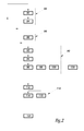
figure 2 is a flow chart of a method of use of the vehicle infigure 1 . - In the remainder of this description the characteristics and functions that are well known to those skill in the art will not be described in detail.
-
Figure 1 shows apublic transport vehicle 2 such as, for example, a bus, streetcar, tram or other. -
Vehicle 2 comprises a DC bus formed by twoelectric conductors - Each of the electric charges is designed to work under a nominal functioning voltage VDCnom. For example, in the
vehicle 2, said voltage VDcnom is above 300 volts DC and preferably above or equal to 350 volts DC. - The electric charges also have a voltage VDcmax beyond which the voltage risks degrading. Here, for example, the voltage VDcmax is above or equal to 400 volts DC.
- In the embodiment shown in
figure 1 , an inverter/rectifier 14 is connected on one side, between theconductors propulsion engine 16 of thevehicle 2. For example, theengine 16 is a three-phase motor/alternator equipped with ashaft 18 suitable to drive in rotation at least onedrive wheel 20 of thevehicle 2. Theengine 16 is also suitable to function as an alternator in order to produce alternating voltage. - The inverter/
rectifier 14 is also connected to a main source ofelectrical energy 24. Hence, when the inverter/rectifier 14 functions as an inverter, it is suitable to feed theengine 16 from thepower source 24 and/or from the DC bus. Conversely, when the inverter/rectifier 14 functions as a rectifier, the alternating voltage generated by theengine 16, when theshaft 18 is driven in rotation by thewheel 20, is transformed into direct voltage delivered onto the DC bus. Aninterrupter 26 allows thesource 24 to be disconnected from the inverter/rectifier 14 when the latter functions as a rectifier. - Here, when the inverter/
rectifier 14 functions as an inverter connected to the DC bus, it is considered as an electric charge connected to said DC bus. - A
battery 30 is also connected between theconductors DC converter 32. - When the
battery 30 is completely charged, it has between its terminals a voltage VBmaX when it is connected to theconverter 32. Conversely, when saidbattery 30 is completely discharged, the voltage between its terminals is equal to VBmin. In practice, the voltage VBmin is never nil. Typically, voltage VBmin is less than 33% of the VBmax voltage and generally, in the range of voltage used, of 20% of the VBmax voltage. Here, the nominal voltage VBnom of thebattery 30 is between 70% and 80% of the VBmax voltage. For example, here the nominal voltage VBnom is equal to 80% of the VBmax voltage. - In this embodiment the
battery 30 is chosen so that it has a VBmin voltage that is strictly higher than the VDCnom voltage and, for example, VDmin is at least 1.5 times higher than the VDCnom voltage . - The value of the VBmax voltage varies according to the age of the
battery 30, i.e. depending on the number of charge and discharge cycles that have taken place. However, it is always possible to choose abattery 30 with VBmin voltage which will definitely always be strictly higher than the VDCnom voltage, even near the end of the battery life. - Here, the
battery 30 is created by connecting in series two rechargeableelectric cells battery 30, each of thecells battery 30 is electrically connected to the DC bus. In order to obtain a VBmin voltage at least twice as high as the VDCnom voltage, here, thecells - Here, the
battery 30 is a NiMH (Nickel Metal Hybrid) battery or a lithium battery. - An
RC filter 34 is connected in parallel to the terminals of theconverter 32 between thebattery 30 and saidconverter 32 so as to filter the voltage produced by theconverter 32. Here, saidfilter 34 is formed by a capacitor C1 connected in parallel to a resistance R1. - A
controllable circuit breaker 36 is also included between thebattery 30 and theconverter 32 so as to be able to isolate thebattery 30 from the group of charges connected to the DC bus. - A
voltage clipper 38 is connected to theconductors clipper 38 is able to clip the voltage contained on the DC bus when it exceeds the VDCmax voltage. Typically, for this purpose the clipper dissipates the excess electrical energy on the DC bus in, for example, a rheostat. - The
converter 32 includes a chopper/step-down converter 40 as well as a chopper/step-upconverter 42. - Here, the chopper/step-
down converter 40 is able to lower the voltage VB at the terminals of thebattery 30 to deliver the electrical energy stored in thebattery 30 to the DC bus under a voltage VDC that is near or equal to the voltage VDCnom. Said chopper/step-down converter is also able to cut a discharge current from thebattery 30 to the DC bus when its amperage is higher than 100 amperes and preferably higher than 300 amperes. - Here, the chopper/step-
down converter 40 is made with the use of an inductor L connected in series with a controllable interrupter I2. More specifically, one end of the inductor L is directly connected to one end of theconductor 6 while itsother end 44 is connected to a first side of the interrupter I2. The other side of the interrupter I2 is connected to the positive terminal of thebattery 30. - For example, the interrupter I2 includes a diode D2 the anode of which is connected to the
end 44 of the inductor L, and a transistor Q2, connected in parallel to the terminals of the diode D2. The transmitter of the transistor Q2 is connected to theend 44 of the inductor L. The transistor Q2 is, for example, an IGBT transistor (Insulated Gate Bipolar Transistor). - The chopper/step-up
converter 42 is able to increase the voltage VDC in the DC bus to produce a voltage VDccharge at the terminals of theRC filter 34. - For this purpose, the chopper/step-up
converter 42 is formed by the inductor coil L and a controllable interrupter I1 connected on one side to theend 44 and on the other to theconductor 8. - For example, the structure of the interrupter I1 is identical to that of the interrupter I2 except for the fact that the diode and the transistor are numbered D1 and Q1 respectively.
- An
ammeter 46 and avoltmeter 47 are also envisaged to measure, respectively, the charge iB or discharge current of thebattery 30, and the voltage VB at the terminals of thebattery 30. - An
ammeter 48 and avoltmeter 49 are envisaged to measure, respectively, the amperage of the current iDC passing through theconductor 6 and the voltage VDC between theconductors - Lastly, the
vehicle 2 includes acontrol unit 50 for theconverter 32 and thecircuit breaker 36. For this purpose, saidunit 50 is electrically connected to theammeters voltmeters Unit 50 is also connected to a non-volatile andrewritable memory 52 containing notably a setting Vconfig the importance of which will become clear in the light of this description. - In this embodiment, the
battery 30, theconverter 32, thefilter 34, thecircuit breaker 36, theammeter 46, thevoltmeter 47, thecontrol unit 50 and thememory 52 are included in abattery pack 54 forming a single removable piece. For this purpose, thebattery pack 54 includesconnectors complementary connectors connectors battery 30 to be electrically connected to theconductors converter 32, while theconnectors ammeter 48 and thevoltmeter 49 to be electrically connected to thecontrol unit 50. - Lastly, the
pack 54 also includes aninterface 64 connected to thememory 52. Saidinterface 64 allows aremovable configuration unit 66 to be connected and disconnected alternately. Theunit 66 also makes it possible to memorise a new value for the Vconfig setting in thememory 52. For this purpose theunit 66 is, for example, equipped with akeyboard 68 and, possibly, ascreen 70. Here, theunit 66 is independent from thebattery pack 54 and from thevehicle 2. - The functioning of the
vehicle 2 shall now be described with reference tofigure 2 . - The method begins with a
stage 80 in which thebattery pack 54 is configured before being assembled inside thevehicle 2. For this purpose, in astep 82, theconfiguration unit 66 is connected to aninterface 64. Then, instep 84, the configuration unit registers a new value for the setting Vconfig. Here, this new value for the setting Vconfig is equal to the voltage VDCnom of the DC bus invehicle 2. - Next, the
unit 6 is disconnected from theinterface 64 and, instep 86, thebattery pack 54 is installed inside the vehicle. Instep 86, with anoperation 88, theconnectors connectors vehicle 2 to electrically connect thebattery pack 54 to the DC bus and to theammeter 48 and thevoltmeter 49. - The
vehicle 2 can now begin to make use of thebattery pack 54. - Let us recall that when the
battery pack 54 is in use, thevoltage clipper 58 continuously clips the VDC voltage so that it is always lower than the VDcmax voltage. - Here we suppose that, initially, the
battery 30 is charged. Hence, the method can continue with astep 90 in which the energy stored in thebattery 30 is released to feed the various charges connected to the DC bus of thevehicle 2. - At the beginning of
step 90, theunit 50 deactivates the chopper/step-upconverter 42, instep 92. For example, duringstep 92, theunit 50 controls the opening of the transistor Q1, then maintains this transistor open for the entire duration ofstep 90. - Next, in
step 94, theunit 50 controls the chopper/step-down converter 40 to lower the voltage VB at the terminals of thebattery 30 so as to deliver the energy stored in said battery under a voltage equal to the setting Vconfig. In thisstep 84, the frequency by which the current iB is cut by the transistor Q2 is regulated according to the voltage VB measured by thevoltmeter 47 and to the value of the setting Vconfig recorded in thememory 52. It is therefore clear that thebattery pack 54 can be connected to DC buses of different vehicles which have different VDCnom voltages, simply by adjusting the value of the setting Vconfig before connecting thebattery pack 54 to the vehicle. - Next, in
step 96, the various charges connected to the DC bus consume the electrical energy supplied by thebattery 30. For example, a part of the electrical energy supplied by thebattery 30 is used by theengine 16 to rotate the drive wheels. - In parallel to step 96, in
step 98, theunit 50 also estimates the state of charge of thebattery 30 by measuring the amount of electrical energy supplied to the DC bus from thebattery 30. This amount of energy can be estimated using measurements of amperage iB and voltage VB. - Also in parallel to
steps step 100, theunit 50 monitors the value of the measured VDC voltage. If it should exceed a pre-set threshold S1, theunit 50 automatically stopsstep 90 and automatically proceeds to astep 110 in which energy is stored in thebattery 30. In effect, raising the VDC voltage means that a surplus of energy is available on the DC bus and it is therefore wise to store this energy surplus in thebattery 30. This rise in the VDC voltage could be caused by thevehicle 2 braking with the help of theengine 16. Indeed, when such braking takes place, theengine 16 functions as an alternator and therefore produces a three-phase current which is then rectified by therectifier 14 and delivered to the DC bus. - At the beginning of
step 110, withstep 112, the step-down converter is deactivated. For example, theunit 50 controls the opening of the transistor Q2 and maintains said transistor open for the entire duration ofstep 110. - Next in
step 114, theunit 50 controls the chopper/step-upconverter 42 to generate a voltage VDCcharge which is strictly higher than the VDC voltage present at the same time on the DC bus. More specifically, theunit 50 controls the chopper/step-upconverter 42 in relation to the VDC voltage and the VB voltage measured as well as in relation to the estimate of the state of charge of thebattery 30 in order to determine the most appropriate value of the VDCcharge voltage for recharging thebattery 30. Indeed, regulating the value of the VDCcharge voltage according to the aforementioned measurements and the state of charge of the battery makes it possible to set the amperage of the current iB, since this amperage depends on the difference between the VB voltage and the VDCcharge voltage. For example, if the state of charge is low, thebattery 30 can be charged with the use of a current iB with a high amperage and in this case, theunit 50 controls the chopper/step-upconverter 42 so that the VDCcharge voltage is significantly higher than the VB voltage. Conversely, if the state of charge of thebattery 30 is already high, the amperage of the current iB must be kept low so as not to damage thebattery 30. Consequently, theunit 50 controls the chopper/step-upconverter 42 so that the VDCcharge voltage is only slightly higher than the VB voltage. - Thus, in
step 114, thebattery 30 is recharged while at the same time controlling the amperage of the current iB. - Simultaneously to step 114, in
step 118, theunit 50 also continues to update the estimate of the state of charge of thebattery 30 calculated using the amperage of the current iB and the VB voltage measured. -
Stage 110 continues as long as the VDC voltage is higher than the threshold S1. When this condition is not fulfilled, the method returns to stage 90. - Simultaneously to
steps unit 50 may proceed to astage 120 of electrical isolation of thebattery 30 from the DC bus. During thisstage 120,unit 50 controls the opening of the transistors Q1 and Q2 simultaneously, and maintains these transistors open while thecircuit breaker 36 is not open. This allows very effective protection, as the cutting time of the transistors Q1 and Q2 is a thousand times shorter than that of thecircuit breaker 36. In such conditions, the amperage of the discharge current is nil andunit 50 can control the opening of thecircuit breaker 36 at that point. - For the purposes of maintenance or in order to recharge the
battery 54 in a way other than using the DC bus, it is possible to proceed to step 130 in which thebattery pack 54 is removed from thevehicle 2. In thisstep 130, theconnectors corresponding connectors battery pack 54 is removed from thevehicle 2. Thebattery pack 54 may then be recharged from an electricity source that is independent from thevehicle 2, by connecting said source to thebattery 30 by means of theconnector 56. - At the end of
step 130 it is possible to either return tostage 80 in order to reset thebattery pack 54 so hat it can be installed in another vehicle, or return directly to step 86 to reinstall thebattery pack 54 in thevehicle 2. - Numerous other embodiments are possible. For example, the chopper/step-
down converter 40 or the chopper/step-upconverter 42 may include various branches in parallel to interrupters I1 or I2. In these conditions, for the same power transmitted from thebattery 30 to the DC bus, the converter can work at a much higher frequency of cutting. This allows the size of the inductor L to be reduced. - As a variation, the
connectors battery pack 54 is not required to be removable. - The
configuration unit 66 can also be integrated inside thebattery pack 54 or inside thevehicle 2.
Claims (10)
- Public transport vehicle including :- a DC bus (8) formed by two conductors (6, 8) between which various electric charges (10, 12, 14) onboard said vehicle are connected in parallel, said electric charges being designed to function under a nominal direct voltage VDCnom, one of said charges (14) being an inverter suitable to feed a propulsion engine of said vehicle, and- a battery (30) connected to the DC bus to feed the various charges with electrical energy stored in said battery, said battery having between its terminals a voltage VBmax when the battery is fully charged, and a voltage VBmin when the battery is discharged, voltages VBmax and VBmin being measured when the battery is electrically connected to the DC buscharacterised in that:- the voltage VDCnom is systematically lower than 33% of the voltage VBmax, and- the vehicle has a controllable step-down DC-DC converter (40) connected on one side to the terminals of the battery (30) and on the other side, to the DC bus, said step-down converter being able to deliver onto the DC bus the electrical energy stored in the battery under a voltage equal to the voltage VDCnom.
- Vehicle according to claim 1, in which:- the battery (30) and the controllable step-down converter (40) are integrated in the same battery pack (54) forming a single removable piece, and- said battery pack (54) and the DC bus have complementary connectors (56, 58, 60, 62) suitable to be attached to each other so as to electrically connect the battery pack to the DC bus and, alternately, to be detached from each other to allow the battery pack to be removed from the vehicle.
- Vehicle according to claim 2, wherein the battery pack (54) includes:- a non-volatile rewritable memory (52) containing a setting Vconfig able to take several different values, and- a control unit (50) able to control the step-down converter so that it delivers the energy stored in the battery to the DC bus under a voltage that is determined according to the value of the setting Vconfig, and- in which the vehicle comprises a configuration unit (66) allowing the value of the setting Vconfig to be adjusted even before the battery pack has been electrically connected to the DC bus.
- Vehicle according to any one of the previous claims, wherein the battery (30) is formed by at least two rechargeable electric cells (31A, 31B) connected in series, each rechargeable cell having a voltage VPmax when it is completely charged, said voltage VPmax being strictly higher than twice the VDCnom voltage for each of the rechargeable electric cells, the voltage VPmax being measured when the battery is electrically connected to the DC bus.
- Vehicle according to any one of the previous claims, wherein the step-down converter (40) is able to cut a discharge current of the battery circulating from the battery to the DC bus, and wherein the vehicle comprises a controllable circuit breaker (36) able to cut the discharge and charge current in order to electrically isolate the battery from the DC bus, and a control unit (50) able to control the step-down converter to cut the discharge current and maintain said discharge current cut off for a pre-set length of time, and to control the opening of the circuit breaker according to the control of the step-down converter, so as to ensure that the circuit breaker is opened when the amperage of the discharge current is nil.
- Vehicle according to any one of the previous claims, wherein the step-down converter (40) is a chopper/step-down converter able to lower the voltage at the terminals of the battery (30) to deliver the electrical energy stored in the battery under a voltage equal to the UDCnom voltage by chopping the discharge current.
- Vehicle according to any one of the previous claims, wherein the vehicle also comprises a step-up DC-DC converter (42) connected, on one side, to the terminals of the battery and, on the other side, to the DC bus, said step-up converter being able to increase the voltage of the DC bus to deliver electrical energy to be stored in the battery under a voltage VDCcharge strictly higher than the VDCnom voltage, and wherein the vehicle includes a control unit (50) for the step-up converter in order to adjust the VDCcharge voltage according to a voltage measured at that moment at the battery terminals.
- Vehicle according to any one of the previous claims, wherein the vehicle comprises a voltage clipper (38) connected to the DC bus, said clipper being able to systematically maintain the voltage on the DC bus lower than or equal to a voltage VDCmax beyond which the electric charges (10, 12, 14) connected to the DC bus risk being degraded, the voltage VDCmax being strictly higher than the voltage VDCnom.
- Method of use of a public transport vehicle according to any one of the previous claims, said method including a stage (90) in which the energy stored in the battery (30) is release onto the DC bus, characterised in that, systematically, for the entire duration of the stage of energy released, only the step-down converter is used.
- Battery pack forming a single removable piece that can be used in a vehicle according to any one of claims 1 to 8, said pack including a battery (30) able to be connected to the DC bus to feed the various electric charges with electrical energy stored in the battery, said battery having between its terminals a voltage VBmax when the battery is fully charged, and a voltage VBmin when the battery is discharged, voltages VBmax and VBmin being measured when the battery is electrically connected to the DC bus,
characterised in that:- the voltage VDCnom is systematically lower than 33% of the voltage VBmax, and- the battery pack also comprises:connectors (56, 58) suitable to be attached to complementary connectors (60, 62) that are joined to the DC bus so as to electrically connect the battery pack to the DC bus and, alternately, to be detached from the complementary connectors so as to allow the battery pack to be removed from the vehicle, and a step-down DC-DC converter (40) connected on one side to the terminals of the battery, and on the other side, to the connectors (56, 58), said step-down converter being able to deliver onto the DC bus the electrical energy stored in the battery under a voltage equal to the voltage VDCnom.
Applications Claiming Priority (1)
| Application Number | Priority Date | Filing Date | Title |
|---|---|---|---|
| FR0701228A FR2912850B1 (en) | 2007-02-21 | 2007-02-21 | TRANSIT VEHICLE, METHOD OF USE AND BATTERY PACK FOR THIS VEHICLE |
Publications (3)
| Publication Number | Publication Date |
|---|---|
| EP2066002A2 true EP2066002A2 (en) | 2009-06-03 |
| EP2066002A3 EP2066002A3 (en) | 2011-04-27 |
| EP2066002B1 EP2066002B1 (en) | 2013-04-03 |
Family
ID=38353603
Family Applications (1)
| Application Number | Title | Priority Date | Filing Date |
|---|---|---|---|
| EP08101786A Active EP2066002B1 (en) | 2007-02-21 | 2008-02-20 | Public transport vehicle, method of use and battery pack for said vehicle |
Country Status (3)
| Country | Link |
|---|---|
| EP (1) | EP2066002B1 (en) |
| ES (1) | ES2414612T3 (en) |
| FR (1) | FR2912850B1 (en) |
Cited By (1)
| Publication number | Priority date | Publication date | Assignee | Title |
|---|---|---|---|---|
| EP3021453A1 (en) * | 2014-11-14 | 2016-05-18 | Iveco France S.A. | Electric power supply circuit for a vehicle and a vehicle equipped with such a circuit |
Family Cites Families (4)
| Publication number | Priority date | Publication date | Assignee | Title |
|---|---|---|---|---|
| US5675232A (en) * | 1989-11-07 | 1997-10-07 | Norand Corporation | Battery pack including electronic power saver |
| JP3245334B2 (en) * | 1995-08-03 | 2002-01-15 | 本田技研工業株式会社 | Power control device for electric vehicle |
| JP4623003B2 (en) * | 2004-02-19 | 2011-02-02 | トヨタ自動車株式会社 | Motor drive device |
| DE102005019116A1 (en) * | 2005-04-25 | 2006-10-26 | Siemens Ag | Battery for an electronic unit, e.g. a motor vehicle control system, is combined in a single unit with a direct voltage converter on a circuit board |
-
2007
- 2007-02-21 FR FR0701228A patent/FR2912850B1/en not_active Expired - Fee Related
-
2008
- 2008-02-20 ES ES08101786T patent/ES2414612T3/en active Active
- 2008-02-20 EP EP08101786A patent/EP2066002B1/en active Active
Cited By (1)
| Publication number | Priority date | Publication date | Assignee | Title |
|---|---|---|---|---|
| EP3021453A1 (en) * | 2014-11-14 | 2016-05-18 | Iveco France S.A. | Electric power supply circuit for a vehicle and a vehicle equipped with such a circuit |
Also Published As
| Publication number | Publication date |
|---|---|
| EP2066002A3 (en) | 2011-04-27 |
| FR2912850A1 (en) | 2008-08-22 |
| ES2414612T3 (en) | 2013-07-22 |
| EP2066002B1 (en) | 2013-04-03 |
| FR2912850B1 (en) | 2012-06-15 |
Similar Documents
| Publication | Publication Date | Title |
|---|---|---|
| CN106926718B (en) | Method and apparatus for charging a plurality of energy storage devices | |
| EP2367258B1 (en) | A combined battery charger and battery equalizer | |
| US9013143B2 (en) | Method for charging a plug-in electric vehicle | |
| JP6293010B2 (en) | Power storage system | |
| US8581557B2 (en) | Direct-current power source apparatus | |
| CA2538299C (en) | Energy storage device for loads having variable power consumption | |
| EP1377477B1 (en) | Energy storage device for loads having variable power rates | |
| US9000614B2 (en) | System for multiple energy storage and management and method of making same | |
| US9444285B2 (en) | Charge controller for vehicle | |
| EP2272722B1 (en) | Power source apparatus for vehicle | |
| US8534400B2 (en) | Electric vehicle and method of control for active auxiliary battery depletion | |
| US9935471B2 (en) | Drive apparatus and transporter | |
| JP6653197B2 (en) | Power storage device, device and control method | |
| US20020145404A1 (en) | Energy storage device and loads having variable power rates | |
| EP2369712A1 (en) | Battery charging apparatus | |
| CN104661856B (en) | Coupling store device for a motor vehicle | |
| US11214171B2 (en) | Mixed battery pack control | |
| JP2013524756A (en) | Self-contained power supply system | |
| JP7397572B2 (en) | vehicle power system | |
| CN101959710B (en) | Energy storage systems for rail vehicles | |
| EP2066002B1 (en) | Public transport vehicle, method of use and battery pack for said vehicle | |
| CA2428403A1 (en) | Energy storage device for loads having variable power rates | |
| CN119489707A (en) | Low voltage charging system for high voltage rechargeable energy storage system | |
| CN121866696A (en) | Power storage system |
Legal Events
| Date | Code | Title | Description |
|---|---|---|---|
| PUAI | Public reference made under article 153(3) epc to a published international application that has entered the european phase |
Free format text: ORIGINAL CODE: 0009012 |
|
| AK | Designated contracting states |
Kind code of ref document: A2 Designated state(s): AT BE BG CH CY CZ DE DK EE ES FI FR GB GR HR HU IE IS IT LI LT LU LV MC MT NL NO PL PT RO SE SI SK TR |
|
| AX | Request for extension of the european patent |
Extension state: AL BA MK RS |
|
| PUAL | Search report despatched |
Free format text: ORIGINAL CODE: 0009013 |
|
| AK | Designated contracting states |
Kind code of ref document: A3 Designated state(s): AT BE BG CH CY CZ DE DK EE ES FI FR GB GR HR HU IE IS IT LI LT LU LV MC MT NL NO PL PT RO SE SI SK TR |
|
| AX | Request for extension of the european patent |
Extension state: AL BA MK RS |
|
| RIC1 | Information provided on ipc code assigned before grant |
Ipc: H02J 7/14 20060101AFI20090428BHEP Ipc: B60L 11/18 20060101ALI20110318BHEP |
|
| 17P | Request for examination filed |
Effective date: 20111025 |
|
| AKX | Designation fees paid |
Designated state(s): AT BE BG CH CY CZ DE DK EE ES FI FR GB GR HR HU IE IS IT LI LT LU LV MC MT NL NO PL PT RO SE SI SK TR |
|
| RIC1 | Information provided on ipc code assigned before grant |
Ipc: B60L 11/18 20060101ALI20120730BHEP Ipc: H02J 7/14 20060101AFI20120730BHEP |
|
| GRAP | Despatch of communication of intention to grant a patent |
Free format text: ORIGINAL CODE: EPIDOSNIGR1 |
|
| GRAS | Grant fee paid |
Free format text: ORIGINAL CODE: EPIDOSNIGR3 |
|
| GRAA | (expected) grant |
Free format text: ORIGINAL CODE: 0009210 |
|
| AK | Designated contracting states |
Kind code of ref document: B1 Designated state(s): AT BE BG CH CY CZ DE DK EE ES FI FR GB GR HR HU IE IS IT LI LT LU LV MC MT NL NO PL PT RO SE SI SK TR |
|
| REG | Reference to a national code |
Ref country code: GB Ref legal event code: FG4D |
|
| REG | Reference to a national code |
Ref country code: CH Ref legal event code: EP Ref country code: AT Ref legal event code: REF Ref document number: 605240 Country of ref document: AT Kind code of ref document: T Effective date: 20130415 |
|
| REG | Reference to a national code |
Ref country code: IE Ref legal event code: FG4D |
|
| REG | Reference to a national code |
Ref country code: DE Ref legal event code: R096 Ref document number: 602008023398 Country of ref document: DE Effective date: 20130529 |
|
| REG | Reference to a national code |
Ref country code: ES Ref legal event code: FG2A Ref document number: 2414612 Country of ref document: ES Kind code of ref document: T3 Effective date: 20130722 |
|
| REG | Reference to a national code |
Ref country code: SE Ref legal event code: TRGR |
|
| REG | Reference to a national code |
Ref country code: AT Ref legal event code: MK05 Ref document number: 605240 Country of ref document: AT Kind code of ref document: T Effective date: 20130403 |
|
| PG25 | Lapsed in a contracting state [announced via postgrant information from national office to epo] |
Ref country code: SI Free format text: LAPSE BECAUSE OF FAILURE TO SUBMIT A TRANSLATION OF THE DESCRIPTION OR TO PAY THE FEE WITHIN THE PRESCRIBED TIME-LIMIT Effective date: 20130403 |
|
| REG | Reference to a national code |
Ref country code: NL Ref legal event code: T3 |
|
| REG | Reference to a national code |
Ref country code: LT Ref legal event code: MG4D |
|
| PG25 | Lapsed in a contracting state [announced via postgrant information from national office to epo] |
Ref country code: BE Free format text: LAPSE BECAUSE OF FAILURE TO SUBMIT A TRANSLATION OF THE DESCRIPTION OR TO PAY THE FEE WITHIN THE PRESCRIBED TIME-LIMIT Effective date: 20130403 Ref country code: IS Free format text: LAPSE BECAUSE OF FAILURE TO SUBMIT A TRANSLATION OF THE DESCRIPTION OR TO PAY THE FEE WITHIN THE PRESCRIBED TIME-LIMIT Effective date: 20130803 Ref country code: NO Free format text: LAPSE BECAUSE OF FAILURE TO SUBMIT A TRANSLATION OF THE DESCRIPTION OR TO PAY THE FEE WITHIN THE PRESCRIBED TIME-LIMIT Effective date: 20130703 Ref country code: GR Free format text: LAPSE BECAUSE OF FAILURE TO SUBMIT A TRANSLATION OF THE DESCRIPTION OR TO PAY THE FEE WITHIN THE PRESCRIBED TIME-LIMIT Effective date: 20130704 Ref country code: LT Free format text: LAPSE BECAUSE OF FAILURE TO SUBMIT A TRANSLATION OF THE DESCRIPTION OR TO PAY THE FEE WITHIN THE PRESCRIBED TIME-LIMIT Effective date: 20130403 Ref country code: AT Free format text: LAPSE BECAUSE OF FAILURE TO SUBMIT A TRANSLATION OF THE DESCRIPTION OR TO PAY THE FEE WITHIN THE PRESCRIBED TIME-LIMIT Effective date: 20130403 Ref country code: FI Free format text: LAPSE BECAUSE OF FAILURE TO SUBMIT A TRANSLATION OF THE DESCRIPTION OR TO PAY THE FEE WITHIN THE PRESCRIBED TIME-LIMIT Effective date: 20130403 Ref country code: PT Free format text: LAPSE BECAUSE OF FAILURE TO SUBMIT A TRANSLATION OF THE DESCRIPTION OR TO PAY THE FEE WITHIN THE PRESCRIBED TIME-LIMIT Effective date: 20130805 |
|
| PG25 | Lapsed in a contracting state [announced via postgrant information from national office to epo] |
Ref country code: BG Free format text: LAPSE BECAUSE OF FAILURE TO SUBMIT A TRANSLATION OF THE DESCRIPTION OR TO PAY THE FEE WITHIN THE PRESCRIBED TIME-LIMIT Effective date: 20130703 Ref country code: CY Free format text: LAPSE BECAUSE OF FAILURE TO SUBMIT A TRANSLATION OF THE DESCRIPTION OR TO PAY THE FEE WITHIN THE PRESCRIBED TIME-LIMIT Effective date: 20130403 Ref country code: PL Free format text: LAPSE BECAUSE OF FAILURE TO SUBMIT A TRANSLATION OF THE DESCRIPTION OR TO PAY THE FEE WITHIN THE PRESCRIBED TIME-LIMIT Effective date: 20130403 Ref country code: LV Free format text: LAPSE BECAUSE OF FAILURE TO SUBMIT A TRANSLATION OF THE DESCRIPTION OR TO PAY THE FEE WITHIN THE PRESCRIBED TIME-LIMIT Effective date: 20130403 Ref country code: HR Free format text: LAPSE BECAUSE OF FAILURE TO SUBMIT A TRANSLATION OF THE DESCRIPTION OR TO PAY THE FEE WITHIN THE PRESCRIBED TIME-LIMIT Effective date: 20130403 |
|
| PG25 | Lapsed in a contracting state [announced via postgrant information from national office to epo] |
Ref country code: CZ Free format text: LAPSE BECAUSE OF FAILURE TO SUBMIT A TRANSLATION OF THE DESCRIPTION OR TO PAY THE FEE WITHIN THE PRESCRIBED TIME-LIMIT Effective date: 20130403 Ref country code: SK Free format text: LAPSE BECAUSE OF FAILURE TO SUBMIT A TRANSLATION OF THE DESCRIPTION OR TO PAY THE FEE WITHIN THE PRESCRIBED TIME-LIMIT Effective date: 20130403 Ref country code: EE Free format text: LAPSE BECAUSE OF FAILURE TO SUBMIT A TRANSLATION OF THE DESCRIPTION OR TO PAY THE FEE WITHIN THE PRESCRIBED TIME-LIMIT Effective date: 20130403 Ref country code: DK Free format text: LAPSE BECAUSE OF FAILURE TO SUBMIT A TRANSLATION OF THE DESCRIPTION OR TO PAY THE FEE WITHIN THE PRESCRIBED TIME-LIMIT Effective date: 20130403 |
|
| PLBE | No opposition filed within time limit |
Free format text: ORIGINAL CODE: 0009261 |
|
| STAA | Information on the status of an ep patent application or granted ep patent |
Free format text: STATUS: NO OPPOSITION FILED WITHIN TIME LIMIT |
|
| PG25 | Lapsed in a contracting state [announced via postgrant information from national office to epo] |
Ref country code: RO Free format text: LAPSE BECAUSE OF FAILURE TO SUBMIT A TRANSLATION OF THE DESCRIPTION OR TO PAY THE FEE WITHIN THE PRESCRIBED TIME-LIMIT Effective date: 20130403 |
|
| 26N | No opposition filed |
Effective date: 20140106 |
|
| REG | Reference to a national code |
Ref country code: DE Ref legal event code: R097 Ref document number: 602008023398 Country of ref document: DE Effective date: 20140106 |
|
| PG25 | Lapsed in a contracting state [announced via postgrant information from national office to epo] |
Ref country code: MC Free format text: LAPSE BECAUSE OF FAILURE TO SUBMIT A TRANSLATION OF THE DESCRIPTION OR TO PAY THE FEE WITHIN THE PRESCRIBED TIME-LIMIT Effective date: 20130403 Ref country code: LU Free format text: LAPSE BECAUSE OF FAILURE TO SUBMIT A TRANSLATION OF THE DESCRIPTION OR TO PAY THE FEE WITHIN THE PRESCRIBED TIME-LIMIT Effective date: 20140220 |
|
| REG | Reference to a national code |
Ref country code: CH Ref legal event code: PL |
|
| PG25 | Lapsed in a contracting state [announced via postgrant information from national office to epo] |
Ref country code: CH Free format text: LAPSE BECAUSE OF NON-PAYMENT OF DUE FEES Effective date: 20140228 Ref country code: LI Free format text: LAPSE BECAUSE OF NON-PAYMENT OF DUE FEES Effective date: 20140228 |
|
| REG | Reference to a national code |
Ref country code: IE Ref legal event code: MM4A |
|
| PG25 | Lapsed in a contracting state [announced via postgrant information from national office to epo] |
Ref country code: IE Free format text: LAPSE BECAUSE OF NON-PAYMENT OF DUE FEES Effective date: 20140220 |
|
| REG | Reference to a national code |
Ref country code: FR Ref legal event code: PLFP Year of fee payment: 8 |
|
| REG | Reference to a national code |
Ref country code: FR Ref legal event code: PLFP Year of fee payment: 9 |
|
| PG25 | Lapsed in a contracting state [announced via postgrant information from national office to epo] |
Ref country code: MT Free format text: LAPSE BECAUSE OF FAILURE TO SUBMIT A TRANSLATION OF THE DESCRIPTION OR TO PAY THE FEE WITHIN THE PRESCRIBED TIME-LIMIT Effective date: 20130403 |
|
| PG25 | Lapsed in a contracting state [announced via postgrant information from national office to epo] |
Ref country code: TR Free format text: LAPSE BECAUSE OF FAILURE TO SUBMIT A TRANSLATION OF THE DESCRIPTION OR TO PAY THE FEE WITHIN THE PRESCRIBED TIME-LIMIT Effective date: 20130403 Ref country code: HU Free format text: LAPSE BECAUSE OF FAILURE TO SUBMIT A TRANSLATION OF THE DESCRIPTION OR TO PAY THE FEE WITHIN THE PRESCRIBED TIME-LIMIT; INVALID AB INITIO Effective date: 20080220 |
|
| REG | Reference to a national code |
Ref country code: FR Ref legal event code: PLFP Year of fee payment: 10 |
|
| REG | Reference to a national code |
Ref country code: FR Ref legal event code: PLFP Year of fee payment: 11 |
|
| REG | Reference to a national code |
Ref country code: NL Ref legal event code: PD Owner name: IVECO FRANCE S.A.S.; FR Free format text: DETAILS ASSIGNMENT: CHANGE OF OWNER(S), CHANGE OF LEGAL ENTITY; FORMER OWNER NAME: IVECO FRANCE S.A. Effective date: 20230406 |
|
| REG | Reference to a national code |
Ref country code: DE Ref legal event code: R081 Ref document number: 602008023398 Country of ref document: DE Owner name: IVECO FRANCE S.A.S., FR Free format text: FORMER OWNER: IVECO FRANCE S.A., VENISSIEUX, FR |
|
| P01 | Opt-out of the competence of the unified patent court (upc) registered |
Effective date: 20230522 |
|
| REG | Reference to a national code |
Ref country code: ES Ref legal event code: PC2A Owner name: IVECO FRANCE S.A.S. Effective date: 20240614 |
|
| PGFP | Annual fee paid to national office [announced via postgrant information from national office to epo] |
Ref country code: NL Payment date: 20260220 Year of fee payment: 19 |
|
| PGFP | Annual fee paid to national office [announced via postgrant information from national office to epo] |
Ref country code: SE Payment date: 20260223 Year of fee payment: 19 |
|
| PGFP | Annual fee paid to national office [announced via postgrant information from national office to epo] |
Ref country code: GB Payment date: 20260223 Year of fee payment: 19 |
|
| PGFP | Annual fee paid to national office [announced via postgrant information from national office to epo] |
Ref country code: ES Payment date: 20260317 Year of fee payment: 19 |
|
| PGFP | Annual fee paid to national office [announced via postgrant information from national office to epo] |
Ref country code: DE Payment date: 20260220 Year of fee payment: 19 |
|
| PGFP | Annual fee paid to national office [announced via postgrant information from national office to epo] |
Ref country code: IT Payment date: 20260209 Year of fee payment: 19 |
|
| PGFP | Annual fee paid to national office [announced via postgrant information from national office to epo] |
Ref country code: FR Payment date: 20260227 Year of fee payment: 19 |