EP2065983A2 - Contact member, holding structure of contact member and electrical connector - Google Patents
Contact member, holding structure of contact member and electrical connector Download PDFInfo
- Publication number
- EP2065983A2 EP2065983A2 EP08170274A EP08170274A EP2065983A2 EP 2065983 A2 EP2065983 A2 EP 2065983A2 EP 08170274 A EP08170274 A EP 08170274A EP 08170274 A EP08170274 A EP 08170274A EP 2065983 A2 EP2065983 A2 EP 2065983A2
- Authority
- EP
- European Patent Office
- Prior art keywords
- press
- contact member
- contact
- housing
- connector
- Prior art date
- Legal status (The legal status is an assumption and is not a legal conclusion. Google has not performed a legal analysis and makes no representation as to the accuracy of the status listed.)
- Withdrawn
Links
- 230000013011 mating Effects 0.000 claims abstract description 46
- 238000003825 pressing Methods 0.000 claims description 16
- 230000009467 reduction Effects 0.000 abstract description 5
- 230000002401 inhibitory effect Effects 0.000 abstract description 4
- 239000002184 metal Substances 0.000 description 7
- 229910052751 metal Inorganic materials 0.000 description 7
- 238000003032 molecular docking Methods 0.000 description 4
- 238000004519 manufacturing process Methods 0.000 description 3
- 238000005452 bending Methods 0.000 description 2
- 230000008901 benefit Effects 0.000 description 2
- 238000000034 method Methods 0.000 description 2
- 229910000881 Cu alloy Inorganic materials 0.000 description 1
- 230000015572 biosynthetic process Effects 0.000 description 1
- 230000008859 change Effects 0.000 description 1
- 238000005520 cutting process Methods 0.000 description 1
- 238000006073 displacement reaction Methods 0.000 description 1
- 230000000694 effects Effects 0.000 description 1
- 239000011295 pitch Substances 0.000 description 1
- 230000008569 process Effects 0.000 description 1
- 229920003002 synthetic resin Polymers 0.000 description 1
- 239000000057 synthetic resin Substances 0.000 description 1
Images








Classifications
-
- H—ELECTRICITY
- H01—ELECTRIC ELEMENTS
- H01R—ELECTRICALLY-CONDUCTIVE CONNECTIONS; STRUCTURAL ASSOCIATIONS OF A PLURALITY OF MUTUALLY-INSULATED ELECTRICAL CONNECTING ELEMENTS; COUPLING DEVICES; CURRENT COLLECTORS
- H01R13/00—Details of coupling devices of the kinds covered by groups H01R12/70 or H01R24/00 - H01R33/00
- H01R13/40—Securing contact members in or to a base or case; Insulating of contact members
- H01R13/405—Securing in non-demountable manner, e.g. moulding, riveting
- H01R13/41—Securing in non-demountable manner, e.g. moulding, riveting by frictional grip in grommet, panel or base
-
- H—ELECTRICITY
- H01—ELECTRIC ELEMENTS
- H01R—ELECTRICALLY-CONDUCTIVE CONNECTIONS; STRUCTURAL ASSOCIATIONS OF A PLURALITY OF MUTUALLY-INSULATED ELECTRICAL CONNECTING ELEMENTS; COUPLING DEVICES; CURRENT COLLECTORS
- H01R12/00—Structural associations of a plurality of mutually-insulated electrical connecting elements, specially adapted for printed circuits, e.g. printed circuit boards [PCB], flat or ribbon cables, or like generally planar structures, e.g. terminal strips, terminal blocks; Coupling devices specially adapted for printed circuits, flat or ribbon cables, or like generally planar structures; Terminals specially adapted for contact with, or insertion into, printed circuits, flat or ribbon cables, or like generally planar structures
- H01R12/70—Coupling devices
- H01R12/71—Coupling devices for rigid printing circuits or like structures
- H01R12/712—Coupling devices for rigid printing circuits or like structures co-operating with the surface of the printed circuit or with a coupling device exclusively provided on the surface of the printed circuit
- H01R12/716—Coupling device provided on the PCB
Definitions
- the present invention relates to a contact member held in an insulative housing of an electrical connector and its holding structure, and particularly relates to a holding structure of a contact member suitable for a low profiled header which is soldered to a printed wiring board.
- an electrical connector which interconnects printed wiring boards (hereinafter, simply called wiring boards) mounted with electronic components in a parallel state inside electronic equipment represented by a personal computer.
- the connector is mounted on each of the wiring boards, and is sometimes called a vertical header.
- a high density connector that is, a connecter which is compact and has a number of contact members has been developed.
- a connector 200 of Japanese Utility Model Laid-Open No. 4-99378 a plurality of terminal plate mating portions 202 are formed in the rear portion of a housing 201, and after terminal units 203 mate with the terminal plate mating portions 202, each of the terminal units 203 is welded to the housing 201 to be fixed to the housing 201.
- a number of contact members 205 and 206 are embedded in a terminal plate 204 which is short in a dimension in a longitudinal direction with a narrow width in two rows at predetermined pitches.
- Contact portions 205a and 206a of the contact members 205 and 206 are disposed in a mating recess 207 along insulative walls 208 formed in the mating recess 207 of the housing 201.
- projections 208a are formed at upper end portions of the insulative walls 208.
- the contact portions 205a and 206a are hidden by the projections 208a.
- the projections 208a are provided to prevent the contact members of a mating connector (not shown) from colliding with the tip ends of the contact portions 205a and 206a when the connector 200 mates with the mating connector.
- mating may become insufficient.
- the contact portions 205a and 206a and even the contact members of the mating connector may be damaged.
- the connector 200 is required to be reduced in height, that is, to reduce its height in correspondence with miniaturization of electronic equipment.
- the connector 200 in which the projections 208a are provided at the tip ends of the insulative walls 208 is disadvantageous for reduction in height. This is because the insulative walls 208 become higher correspondingly to formation of the projections 208a.
- a connector 300 described in Japanese Patent Laid-Open No. 2001-102120 is not provided with the projections 208a at the upper ends of the insulative walls 208 as in the above described connector 200 and therefore, the connector 300 can be reduced in height.
- a contact member 303 is restrained to a housing 301 by press-fitting only its raised portion into a bottom floor 301b. Accordingly, when a force is applied to a tine portion 303b of the contact member 303 in the direction shown by an arrow, the contact member 303 rotates in the direction shown by an arrow around the press-fitted portion. Thereupon, a contact portion 303a displaces in the direction to be away from an insulative wall 302. Thereupon, the contact portion 303a is likely to collide with a contact portion 304a of a contact member 304 of a mating connector.
- lift displacement of the contact portion 303a in the direction to be away from the insulative wall 302
- the contact member 303 When the thickness of the bottom floor 301b of the housing 301 becomes thin, the contact member 303 easily rotates when a force is applied to the tine portion 303b in the direction shown by the arrow. This is because the length of the bottom floor 301b which restrains the contact member 303 becomes short.
- the connector 300 When the connector 300 is reduced in height, a predetermined mating length needs to be ensured, and therefore, the thickness of the bottom floor 301b is made thin. Accordingly, when the connector 300 is reduced in height, the contact portion 303a is easily lifted from the insulative wall 302.
- the present invention is made in view of the technical problem described above, and has an object to provide a contact member capable of preventing a contact portion from being lifted from an insulative wall of a housing without inhibiting reduction in height. Furthermore, the present invention has an object to provide a holding structure of the contact member and a connector which prevent the contact portion from being lifted from the insulative wall by using the contact member.
- a contact member of the present invention which attains the above described object is a contact member of a connector, which is held in a housing including a press-fit hole and a support surface and is connected to a mating contact member.
- the contact member is characterized by including a flat contact portion for contact with the mating contact member, and disposed along the support surface, a flat press-fit fixing portion which is connected to the contact portion and is press-fitted into the press-fit hole, a tine portion connected to the press-fit fixing portion, and a lug extending from a side surface of the press-fit fixing portion, and is characterized in that the lug includes a projected portion projected to the support surface side from the contact portion, and the projected portion is disposed at a side opposite from the contact portion with respect to the press-fit fixing portion.
- the contact member according to the present invention When the contact member according to the present invention is held in the housing, the projected portion is pressed by the support surface, and thereby, the lug receives the force in the direction to be away from the support surface. As a result, the contact portion connected via the press-fit fixing portion is pressed to the support surface with the press-fit fixing portion as a center. In this manner, the present invention prevents the contact portion from being lifted from the support wall.
- the lug in the contact member of the present invention may be in any shape, as long as the lug includes a support piece which is connected to the press-fit fixing portion and is provided on the same plane as the contact portion, and an inclined piece which is extended from the support piece in a direction in which the mating contact member is inserted, with a tip end of it being inclined to be in contact with or closely adjacent to or close to the support surface.
- the lug of the contact member can be formed without adding a new process step, in the process of manufacturing the contact.
- the lugs are preferably provided at both side surfaces in a width direction of the press-fit fixing portion. This is because the contact portion can be more reliably pressed to the support surface.
- the present invention provides a holding structure of a contact member using the above contact member. More specifically, the present invention provides a holding structure of a contact member with respect to a housing, in which a press-fit fixing portion is press-fitted into a press-fit hole formed in the housing, and a contact portion is disposed along a support surface formed in the housing, and is characterized in that the contact member includes the flat contact portion which is in contact with a mating contact member, and is disposed along the support surface, a flat press-fit fixing portion which is connected to the contact portion and press-fitted into the press-fit hole, a tine portion connected to the press-fit fixing portion, and a lug extending from a side surface of the press-fit fixing portion, the lug includes a projected portion projected to the support surface side from the contact portion, and the projected portion is disposed at a side opposite from the contact portion with respect to the press-fit fixing portion.
- the housing is characterized by including a pressing surface which presses the projected portion of the lug.
- the lug preferably includes a support piece which is connected to the press-fit fixing portion and is provided on the same plane as the contact portion, and an inclined piece which is extended from the support piece in a direction in which the mating contact member is inserted, with a tip end of it being inclined to be close to the support surface.
- the tip end of the inclined piece is pressed by the pressing surface.
- the lugs are preferably provided at both side surfaces in a width direction of the press-fit fixing portion, and in this case, the pressing surfaces are provided at both sides in a width direction of the press-fit hole.
- the present invention provides a connector using the above contact member.
- the connector comprises a first connector mounted on a first printed wiring board or printed circuit board, and a second connector mating with the first connector and mounted on a second printed wiring board or printed circuit board.
- Any one of the first connector and the second connector includes a housing including a press-fit hole and a support surface, and a plurality of contact members held in the housing, at least one of the contact members includes a flat contact portion which is in contact with a mating contact member, and is disposed along the support surface, a flat press-fit fixing portion which is connected to the contact portion and press-fitted into the press-fit hole, a tine portion connected to the press-fit fixing portion, and a lug extending from a side surface of the press-fit fixing portion, the lug includes a projected portion projected to the support surface side from the contact portion, and the projected portion is disposed at a side opposite from the contact portion with respect to the press-fit fixing portion.
- the housing is characterized by including a pressing surface
- the lug also preferably includes a support piece which is connected to the press-fit fixing portion and is provided on the same plane as the contact portion, and an inclined piece which is extended from the support piece in a direction in which the mating contact member is inserted, with a tip end of it being inclined to be close to the support surface, and the tip end of the inclined piece is pressed by the pressing surface.
- the lugs are preferably provided at both side surfaces in a width direction of the press-fit fixing portion, and in this case, the pressing surfaces are provided at both sides in a width direction of the press-fit hole.
- a connector capable of preventing a contact member from being lifted up without inhibiting reduction in height can be provided.
- the present embodiment is an example in which the present invention is applied to a docking connector which connects a notebook type personal computer (hereinafter, called a note PC) and a docking station, which is an extension unit, to each other.
- a docking connector which connects a notebook type personal computer (hereinafter, called a note PC) and a docking station, which is an extension unit, to each other.
- a housing 4 constitutes a plug connector 10 of the present embodiment.
- the plug connector 10 is placed on a top surface of the docking station.
- the plug connector 10 has the insulative elongated housing 4, and contact members 8 and 9 which are held in a mating portion 6 of the housing 4 in four rows along a longitudinal direction L of the housing 4.
- the contact member 8 is a contact member with a narrow width for a signal
- the contact member 9 is a contact member with a large width for power supply.
- the housing 4 has a main body 14 in a rectangular parallelepiped shape extending in the longitudinal direction L, and mounting portions 12 and 12 each in a rectangular parallelepiped shape which are located at both ends of it.
- the main body 14 and the mounting portions 12 and 12 are integrally molded from a synthetic resin.
- Each of the mounting portions 12 is mounted with a holding metal fitting 22.
- the holding metal fitting 22 has a holding leg 18 which extends to the side of a wiring board or circuit board on which the plug connector 10 is mounted. The holding leg 18 is used when the plug connector 10 is mounted on the wiring board.
- Guide posts 26 for being inserted into guide holes 118 of a receptacle connector 100 which will be described later are projectingly provided at both ends of the mating portion 6 in the mating direction.
- the guide post 26 performs a guide function and a lock function.
- the housing 4 is mounted with shield shells (hereinafter, simply called shells) 28 and 28.
- the shell 28 is formed by being stamped out of one metal sheet and bent.
- the housing 4 has mating grooves 44 in the mating portion 6 in two rows along the longitudinal direction L, and a plurality of contact receiving grooves 44a and 44b are formed at both sides of the mating groove 44.
- the contact receiving grooves 44a and 44b are respectively formed in accordance with the widths of the contact members 8 and 9.
- the contact members 8 are disposed in the contact receiving groove 44a, and the contact members 9 are disposed in the contact receiving groove 44b.
- the mating receptacle connector 100 which mates with the plug connector 10 will be described with reference to FIGS. 4 to 6 and there is a housing 104 of the receptacle connector 100.
- the receptacle connector 100 is placed on the bottom surface of a note PC.
- the receptacle connector 100 has an insulative housing 104 in a rectangular parallelepiped shape, and a shield shell (hereinafter, simply called a shell) 128 made of a metal constituted to cover a side wall 115 of the housing 104, and a plurality of contact members 108 and 109 held in the housing 104.
- the contact members 108 and 109 are respectively connected to the contact members 8 and 9 of the plug connector 10.
- a mating recess 101 extending along the longitudinal direction L is formed.
- mating ribs 144 in two rows which mate with the mating grooves 44 of the plug connector 10 are formed integrally with the housing 104 along the longitudinal direction L.
- On the side surface of the mating rib 144 a plurality of contact receiving grooves 144a and 144b are formed.
- the contact receiving grooves 144a and 144b are respectively formed in accordance with the width of the contacts.
- the contact members 108 are disposed in the contact receiving groove 144a, and the contact members 109 are disposed in the contact receiving groove 144b.
- the contact members 108 and 109 are disposed in the contact receiving grooves 144a and 144b, and are placed in rows at both sides of each of the mating ribs 144.
- Guide holes 118 for receiving the guide posts 26 of the plug connector 10 to be the mating connector are formed at both end portions in the longitudinal direction L of the housing 104.
- the contact members 108 and 109 have tine portions 108a and 109c which are respectively connected to wiring boards (not shown), and the tine portions 108a and 109c are exposed from the undersurface of the housing 104.
- the present embodiment has a characteristic in the shape of the contact member of the receptacle connector 100.
- the characteristic prevents the contact portion from being lifted from the insulative wall without inhibiting reduction in height of the docking connector constituted of the plug connector 10 and the receptacle connector 100 according to the present embodiment.
- the characteristic will be described with the contact member 109 for power supply which is held by the receptacle connector 100 being taken as an example.
- the contact member 109 is taken as an example, but it goes without saying that the present invention can be applied to the contact members 8 and 9 and 108.
- the contact member 109 is L-shaped in the vertical section, and comprises a contact portion 109a, a press-fit fixing portion 109b, a tine portion 109c, and lugs 109d.
- the contact member 109 by stamping out and bending a thin metal plate with a high electric conductivity such as a copper alloy, for example, the contact portion 109a, the press-fit fixing portion 109b, the tine portion 109c and the lugs 109d are integrally formed.
- the contact member 109 is made of a thin metal plate, and therefore, each of the components has resiliency.
- the contact portion 109a is the region for contact with the contact member 9 of the mating connector.
- a free end side of the contact portion 109a will be called a front end, and a side connecting to the tine portion 109c will be called a rear end.
- the contact portion 109a is connected at the rear end to the press-fit fixing portion 109b which is press-fitted into a bottom floor 116 of the housing 104.
- the contact portion 109a is received by the contact receiving groove 144b of the housing 104.
- the tine portion 109c is electrically connected to a wiring board or circuit board mounted with the receptacle connector 100.
- the tine portion 109c has its one end connected to the press-fit fixing portion 109b. Furthermore, the tine portion 109c forms an angle of about 90° with respect to the contact portion 109a.
- the above contact portion 109a, press-fit fixing portion 109b and the tine portion 109c are similar to the respective portions of a known contact.
- the lugs 109d are provided at both side surfaces opposed to the width direction of the press-fit fixing portion 109b.
- the lug 109d comprises a support piece 109d1 extending from a side surface of the contact portion 109a, and an inclined piece 109d2 which is connected to the support piece 109d1 and extends toward the rear end.
- the support piece 109d1 is provided on the same plane as the contact portion 109a.
- the inclined piece 109d2 is provided to form a predetermined angle ⁇ with respect to the support piece 109d1 and with respect to the contact portion 109a.
- the inclined piece 109d2 has elasticity, and functions as a spring.
- the contact portion 109a is formed integrally with the lugs 109d. Further, the inclined pieces 109d2 are disposed at the opposite side from the contact portion 109a with respect to the press-fit fixing portion 109b.
- FIGS. 8A to 8C are views showing a conventional contact member 09.
- the components corresponding to the contact portion 109a, the tine portion 109c and the lug 109d of the contact member 109 according to the present invention are assigned with reference numerals and characters 09a, 09b and 09c, respectively.
- the conventional contact member 09 differs from the contact member 109 according to the present invention in that the entire lug 09d is provided on the same plane as the contact portion 09a.
- the contact member 109 is inserted into the housing 104 in the direction of the solid line arrow.
- the contact member 109 is press-fitted into the housing 104 of the receptacle connector 100 from below.
- the contact portion 109a of the contact member 109 is received in the contact receiving groove 144a formed in the mating rib 144. Furthermore, the press-fit fixing portion 109b of the contact member 109 is press-fitted into a press-fit hole 144c formed in the bottom floor 116 of the housing 104. The contact member 109 is restrained by the housing 104 by only the press-fit fixing portion 109b.
- the lugs 109d are located at both ends in the width direction of the press-fit hole 144c. Meanwhile, pressing surfaces 144d formed on the same plane as the support surface S are formed at the positions corresponding to the lugs 109d.
- a force is assumed to be applied to the tine portion 109c of the contact member 109 in the direction of the outlined arrow.
- the contact member 109 is restrained by the housing 104 by only the press-fit fixing portion 109b, and therefore, the contact member 109 is to rotate in the direction shown by the outlined arrow with the press-fit fixing portion 109b as a center.
- the inclined pieces 109d2 of the lugs 109d are projected to the support surface S side from the contact portion 109a, and therefore, are pressed by the pressing surfaces 144d in the press-fit hole 144c.
- the contact portion 109a is formed integrally with the inclined pieces 109d2 via the press-fit fixing portion 109b, a force pressing to the support surface S is applied to the contact portion 109a as shown by the outlined arrow. This force prevents the contact portion 109a from being lifted from the support surface S.
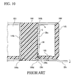
- FIG. 10 is a view in which the contact member 109 of FIG. 9 is replaced with the conventional contact member 09.
- the lugs 09d are disposed parallel along the support surface S. Accordingly, when a force is applied to the tine portion 09c in the arrow direction, the contact portion 09a rotates in the arrow direction as a whole with the press-fit fixing portion 09b as the center, and as a result of it, the contact portion 09a is lifted from the support surface S.
- the contact member 109 even if a force is applied to the tine portion 109c in the direction of the arrow shown in FIG. 9 , the inclined pieces 109d2 are pressed by the pressing surfaces 144d, whereby a force which presses the contact portion 109a against the support surface S occurs, and the contact portion 109a is not lifted from the support surface S.
- the contact member 109 can prevent the contact portion 109a from being lifted from the support surface S in the state in which the contact member 109 is held in the housing 104 by constituting the lugs 109d, which generate a force which presses the contact portion 109a to the support surface S of the mating rib 144, integrally with the contact portion 109a.
- the effect can be obtained without making the bottom floor 116 of the housing 104 thick.
- the present embodiment has the advantage of being capable of preventing the contact portion 109a from being lifted from the support surface S by only forming the inclined pieces 109d2 at part of the lugs 109d without adding a new member.
- this point will be described with reference to FIG. 11 .
- FIG. 11 shows the state in which an intermediate body 109M of the contact member 109 is formed by stamping out a thin metal plate.
- FIG. 11 also shows the example in which the intermediate bodies of another kind of contact member are simultaneously formed.
- the portions corresponding to the lugs 109d of the contact member 109 are connected to a carrier C via a notch portion, and the contact member 109 is finally cut off from the carrier C by being cut at a predetermined position.
- the notch portion is a portion which is formed to have a narrow width to be capable of being easily cut off or broken off from the carrier C. Bending of the tine portion 109c and the inclined pieces 109d2 is performed either before or after cutting the carrier C, and the inclined pieces 109d2 can be bent simultaneously with the tine portion 109c.
- the intermediate bodies 109M of the contact member 109 and the intermediate bodies of another kind of contact member can be handled together, and can be stamped out together, and work such as bending can be applied, whereby high productivity can be ensured.
- the lugs 109d are produced by using the notch portion connecting the carrier C and the intermediate body 109M of the contact member 109 when such a production method is adopted. Therefore, according to the present embodiment, the advantage of being capable of preventing the contact portion 109a from being lifted from the support surface S is provided without an increase in cost.
- the inclined pieces 109d2 are provided in the lugs 109d, but other constitutions can be adopted as long as they exhibit similar functions.
- a projection can be provided instead of the inclined piece 109d2.
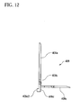
- FIG. 12 shows an example of it.
- a contact member 409 includes a press-fit fixing portion 409b and a tine portion 409c, and a lug 409d is formed on the same plane as the contact portion 409a, but a projection 409d2 projected to the support surface S side of the mating rib 144 is formed at a tip end of the lug 409d.
- the L-shaped contact member 109 is described, but the present invention is not limited to this mode.
- the present invention can be also applied to a contact member 509 which is constituted of a contact portion 509a, a press-fit fixing portion 509b, a tine portion 509c and lugs 509d, and is in a flat I-shape as a whole.
- the lug 509d has a similar constitution and function as the above described lug 109d.
- the L-shaped contact member 109 is used in the case of constituting a surface mounting connector, and the I-shaped contact member 509 is used in the case of constituting a connector which is mounted on a circuit board with a through-hole being formed.
- the inclined pieces 109d2 are provided at the lug 109d at both sides of the contact member 109, but the present invention includes the mode in which the inclined piece 109d2 is provided at only one side of the contact member 109.
- the mode of providing the inclined piece 109d2 at only one side of the contact member 109 should be adopted in the case in which the width of the contact portion 109a is relatively narrow.
- the lug which generates a force which presses the flat contact portion to the support surface is formed integrally with the contact portion.
Landscapes
- Coupling Device And Connection With Printed Circuit (AREA)
- Connector Housings Or Holding Contact Members (AREA)
Abstract
A connecter capable of preventing a contact member from being lifted up without inhibiting reduction in height is provided. A contact member (109) of an electrical connector is held in a housing (104) including a press-fit hole (144c) and a support surface (S). The contact member (109) is to be connected to a mating contact member and includes a flat contact portion (109a) for contact with the mating contact member, and is disposed along the support surface (S). The contact member (109) has a flat press-fit fixing portion (109b) which is connected to the contact portion (109a), and is press-fitted into the press-fit hole (144c). The contact member (109) also has a tine portion (109c) connected to the press-fit fixing portion (109b), and a lug (109d) extending from a side surface of the press-fit fixing portion (109b). The lug (109d) includes a support piece and an inclined piece.
Description
- The present invention relates to a contact member held in an insulative housing of an electrical connector and its holding structure, and particularly relates to a holding structure of a contact member suitable for a low profiled header which is soldered to a printed wiring board.
- There is known an electrical connector (hereinafter, simply called a connector) which interconnects printed wiring boards (hereinafter, simply called wiring boards) mounted with electronic components in a parallel state inside electronic equipment represented by a personal computer. The connector is mounted on each of the wiring boards, and is sometimes called a vertical header.
- As disclosed in, for example, Japanese Utility Model Laid-Open No.
4-99378 FIG. 14 , in aconnector 200 of Japanese Utility Model Laid-Open No.4-99378 plate mating portions 202 are formed in the rear portion of ahousing 201, and afterterminal units 203 mate with the terminalplate mating portions 202, each of theterminal units 203 is welded to thehousing 201 to be fixed to thehousing 201. In theterminal unit 203, a number ofcontact members terminal plate 204 which is short in a dimension in a longitudinal direction with a narrow width in two rows at predetermined pitches. Contactportions contact members mating recess 207 alonginsulative walls 208 formed in themating recess 207 of thehousing 201. - In the
connector 200,projections 208a are formed at upper end portions of theinsulative walls 208. In plan view, thecontact portions projections 208a. Specifically, theprojections 208a are provided to prevent the contact members of a mating connector (not shown) from colliding with the tip ends of thecontact portions connector 200 mates with the mating connector. When the contact members of the mating connector collide with the tip ends of thecontact portions contact portions - The
connector 200 is required to be reduced in height, that is, to reduce its height in correspondence with miniaturization of electronic equipment. However, theconnector 200 in which theprojections 208a are provided at the tip ends of theinsulative walls 208 is disadvantageous for reduction in height. This is because theinsulative walls 208 become higher correspondingly to formation of theprojections 208a. - As shown in
FIG. 15 , aconnector 300 described in Japanese Patent Laid-Open No.2001-102120 projections 208a at the upper ends of theinsulative walls 208 as in the above describedconnector 200 and therefore, theconnector 300 can be reduced in height. - Incidentally, a
contact member 303 is restrained to ahousing 301 by press-fitting only its raised portion into abottom floor 301b. Accordingly, when a force is applied to atine portion 303b of thecontact member 303 in the direction shown by an arrow, thecontact member 303 rotates in the direction shown by an arrow around the press-fitted portion. Thereupon, acontact portion 303a displaces in the direction to be away from aninsulative wall 302. Thereupon, thecontact portion 303a is likely to collide with acontact portion 304a of acontact member 304 of a mating connector. Hereinafter, displacement of thecontact portion 303a in the direction to be away from theinsulative wall 302 will be called "lift" of the contact portion. - When the thickness of the
bottom floor 301b of thehousing 301 becomes thin, thecontact member 303 easily rotates when a force is applied to thetine portion 303b in the direction shown by the arrow. This is because the length of thebottom floor 301b which restrains thecontact member 303 becomes short. When theconnector 300 is reduced in height, a predetermined mating length needs to be ensured, and therefore, the thickness of thebottom floor 301b is made thin. Accordingly, when theconnector 300 is reduced in height, thecontact portion 303a is easily lifted from theinsulative wall 302. - The present invention is made in view of the technical problem described above, and has an object to provide a contact member capable of preventing a contact portion from being lifted from an insulative wall of a housing without inhibiting reduction in height. Furthermore, the present invention has an object to provide a holding structure of the contact member and a connector which prevent the contact portion from being lifted from the insulative wall by using the contact member.
- A contact member of the present invention which attains the above described object is a contact member of a connector, which is held in a housing including a press-fit hole and a support surface and is connected to a mating contact member. The contact member is characterized by including a flat contact portion for contact with the mating contact member, and disposed along the support surface, a flat press-fit fixing portion which is connected to the contact portion and is press-fitted into the press-fit hole, a tine portion connected to the press-fit fixing portion, and a lug extending from a side surface of the press-fit fixing portion, and is characterized in that the lug includes a projected portion projected to the support surface side from the contact portion, and the projected portion is disposed at a side opposite from the contact portion with respect to the press-fit fixing portion.
- When the contact member according to the present invention is held in the housing, the projected portion is pressed by the support surface, and thereby, the lug receives the force in the direction to be away from the support surface. As a result, the contact portion connected via the press-fit fixing portion is pressed to the support surface with the press-fit fixing portion as a center. In this manner, the present invention prevents the contact portion from being lifted from the support wall.
- The lug in the contact member of the present invention may be in any shape, as long as the lug includes a support piece which is connected to the press-fit fixing portion and is provided on the same plane as the contact portion, and an inclined piece which is extended from the support piece in a direction in which the mating contact member is inserted, with a tip end of it being inclined to be in contact with or closely adjacent to or close to the support surface. The lug of the contact member can be formed without adding a new process step, in the process of manufacturing the contact.
- Furthermore, the lugs are preferably provided at both side surfaces in a width direction of the press-fit fixing portion. This is because the contact portion can be more reliably pressed to the support surface.
- The present invention provides a holding structure of a contact member using the above contact member. More specifically, the present invention provides a holding structure of a contact member with respect to a housing, in which a press-fit fixing portion is press-fitted into a press-fit hole formed in the housing, and a contact portion is disposed along a support surface formed in the housing, and is characterized in that the contact member includes the flat contact portion which is in contact with a mating contact member, and is disposed along the support surface, a flat press-fit fixing portion which is connected to the contact portion and press-fitted into the press-fit hole, a tine portion connected to the press-fit fixing portion, and a lug extending from a side surface of the press-fit fixing portion, the lug includes a projected portion projected to the support surface side from the contact portion, and the projected portion is disposed at a side opposite from the contact portion with respect to the press-fit fixing portion. The housing is characterized by including a pressing surface which presses the projected portion of the lug.
- In the above holding structure of the contact member, the lug preferably includes a support piece which is connected to the press-fit fixing portion and is provided on the same plane as the contact portion, and an inclined piece which is extended from the support piece in a direction in which the mating contact member is inserted, with a tip end of it being inclined to be close to the support surface. In the holding structure, the tip end of the inclined piece is pressed by the pressing surface.
- Furthermore, in the above holding structure of the contact member, the lugs are preferably provided at both side surfaces in a width direction of the press-fit fixing portion, and in this case, the pressing surfaces are provided at both sides in a width direction of the press-fit hole.
- The present invention provides a connector using the above contact member. The connector comprises a first connector mounted on a first printed wiring board or printed circuit board, and a second connector mating with the first connector and mounted on a second printed wiring board or printed circuit board. Any one of the first connector and the second connector includes a housing including a press-fit hole and a support surface, and a plurality of contact members held in the housing, at least one of the contact members includes a flat contact portion which is in contact with a mating contact member, and is disposed along the support surface, a flat press-fit fixing portion which is connected to the contact portion and press-fitted into the press-fit hole, a tine portion connected to the press-fit fixing portion, and a lug extending from a side surface of the press-fit fixing portion, the lug includes a projected portion projected to the support surface side from the contact portion, and the projected portion is disposed at a side opposite from the contact portion with respect to the press-fit fixing portion. The housing is characterized by including a pressing surface which presses the projected portion of the lug.
- In the above connector, the lug also preferably includes a support piece which is connected to the press-fit fixing portion and is provided on the same plane as the contact portion, and an inclined piece which is extended from the support piece in a direction in which the mating contact member is inserted, with a tip end of it being inclined to be close to the support surface, and the tip end of the inclined piece is pressed by the pressing surface.
- Furthermore, in the above connector, the lugs are preferably provided at both side surfaces in a width direction of the press-fit fixing portion, and in this case, the pressing surfaces are provided at both sides in a width direction of the press-fit hole.
- According to the present invention, a connector capable of preventing a contact member from being lifted up without inhibiting reduction in height can be provided.
- Hereinafter, a preferred embodiment of a connector according to the present invention will be described in detail with reference to the accompanying drawings, in which:-
-
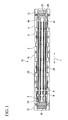
FIG. 1 is a plan view of a plug connector according to the present embodiment; -
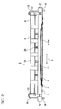
FIG. 2 is a front view of the plug connector ofFIG. 1 ; -
FIG. 3 is a perspective view of a housing constituting the plug connector ofFIG. 1 ; -
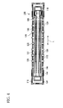
FIG. 4 is a plan view of a receptacle connector which mates with the plug connector ofFIG. 1 ; -
FIG. 5 is a front view of the receptacle connector ofFIG. 4 ; -
FIG. 6 is a perspective view of a housing constituting the receptacle connector ofFIG. 4 ; -
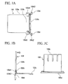
FIGS. 7A to 7C are views showing a contact member used in the plug connector ofFIG. 1 ,FIG. 7A shows a front view,FIG. 7B shows a side view andFIG. 7C shows a plan view; -
FIGS. 8A to 8C are views showing a conventional contact member,FIG. 8A shows a front view,FIG. 8B shows a side view, andFIG. 8C shows a plan view; -
FIG. 9 is a partial sectional view showing the state in which the contact member according to the present invention is held in the housing of the receptacle connector; -
FIG. 10 is a partial sectional view showing the state in which the conventional contact member is held in the housing of the receptacle connector; -
FIG. 11 is a view showing the state of the contact members in the manufacturing process; -
FIG. 12 is a view showing another example of the contact member according to the present invention; -
FIGS. 13A and 13B are views showing another example of the contact member according to the present invention,FIG. 13A shows a front view, andFIG. 13B shows a side view; -
FIG. 14 is a sectional view showing the connector disclosed in Japanese Utility Model Laid-Open No.4-99378 -
FIG. 15 is a perspective view showing the connector disclosed in Japanese Patent Laid-Open No.2001-102120 - The present embodiment is an example in which the present invention is applied to a docking connector which connects a notebook type personal computer (hereinafter, called a note PC) and a docking station, which is an extension unit, to each other.
- Referring to
FIGS. 1 to 3 , ahousing 4 constitutes aplug connector 10 of the present embodiment. Theplug connector 10 is placed on a top surface of the docking station. - The
plug connector 10 has the insulative elongatedhousing 4, andcontact members mating portion 6 of thehousing 4 in four rows along a longitudinal direction L of thehousing 4. - The
contact member 8 is a contact member with a narrow width for a signal, and thecontact member 9 is a contact member with a large width for power supply. - The
housing 4 has amain body 14 in a rectangular parallelepiped shape extending in the longitudinal direction L, and mountingportions main body 14 and the mountingportions - Each of the mounting
portions 12 is mounted with a holdingmetal fitting 22. The holding metal fitting 22 has a holdingleg 18 which extends to the side of a wiring board or circuit board on which theplug connector 10 is mounted. The holdingleg 18 is used when theplug connector 10 is mounted on the wiring board. - Guide posts 26 for being inserted into
guide holes 118 of areceptacle connector 100 which will be described later are projectingly provided at both ends of themating portion 6 in the mating direction. Theguide post 26 performs a guide function and a lock function. - The
housing 4 is mounted with shield shells (hereinafter, simply called shells) 28 and 28. Theshell 28 is formed by being stamped out of one metal sheet and bent. - Next, the
housing 4 hasmating grooves 44 in themating portion 6 in two rows along the longitudinal direction L, and a plurality ofcontact receiving grooves mating groove 44. Thecontact receiving grooves contact members contact members 8 are disposed in thecontact receiving groove 44a, and thecontact members 9 are disposed in thecontact receiving groove 44b. - Next, the
mating receptacle connector 100 which mates with theplug connector 10 will be described with reference toFIGS. 4 to 6 and there is ahousing 104 of thereceptacle connector 100. Thereceptacle connector 100 is placed on the bottom surface of a note PC. - The
receptacle connector 100 has aninsulative housing 104 in a rectangular parallelepiped shape, and a shield shell (hereinafter, simply called a shell) 128 made of a metal constituted to cover aside wall 115 of thehousing 104, and a plurality ofcontact members housing 104. Thecontact members contact members plug connector 10. - In the
housing 104, amating recess 101 extending along the longitudinal direction L is formed. In themating recess 101,mating ribs 144 in two rows which mate with themating grooves 44 of theplug connector 10 are formed integrally with thehousing 104 along the longitudinal direction L. On the side surface of themating rib 144, a plurality ofcontact receiving grooves contact receiving grooves contact members 108 are disposed in thecontact receiving groove 144a, and thecontact members 109 are disposed in thecontact receiving groove 144b. Thecontact members contact receiving grooves mating ribs 144. - Guide holes 118 for receiving the guide posts 26 of the
plug connector 10 to be the mating connector are formed at both end portions in the longitudinal direction L of thehousing 104. - The
contact members tine portions tine portions housing 104. - When the
plug connector 10 and thereceptacle connector 100 which are constituted as above are mated with each other, thecontact members 8 and thecontact members 108 are connected, and thecontact members 9 and thecontact members 109 are connected. - The present embodiment has a characteristic in the shape of the contact member of the
receptacle connector 100. The characteristic prevents the contact portion from being lifted from the insulative wall without inhibiting reduction in height of the docking connector constituted of theplug connector 10 and thereceptacle connector 100 according to the present embodiment. The characteristic will be described with thecontact member 109 for power supply which is held by thereceptacle connector 100 being taken as an example. Here, thecontact member 109 is taken as an example, but it goes without saying that the present invention can be applied to thecontact members - Referring to
FIGS. 7A to 7C , thecontact member 109 is L-shaped in the vertical section, and comprises acontact portion 109a, a press-fit fixing portion 109b, atine portion 109c, and lugs 109d. In thecontact member 109, by stamping out and bending a thin metal plate with a high electric conductivity such as a copper alloy, for example, thecontact portion 109a, the press-fit fixing portion 109b, thetine portion 109c and thelugs 109d are integrally formed. Thecontact member 109 is made of a thin metal plate, and therefore, each of the components has resiliency. - The
contact portion 109a is the region for contact with thecontact member 9 of the mating connector. Here, a free end side of thecontact portion 109a will be called a front end, and a side connecting to thetine portion 109c will be called a rear end. Thecontact portion 109a is connected at the rear end to the press-fit fixing portion 109b which is press-fitted into abottom floor 116 of thehousing 104. Thecontact portion 109a is received by thecontact receiving groove 144b of thehousing 104. - The
tine portion 109c is electrically connected to a wiring board or circuit board mounted with thereceptacle connector 100. Thetine portion 109c has its one end connected to the press-fit fixing portion 109b. Furthermore, thetine portion 109c forms an angle of about 90° with respect to thecontact portion 109a. - The
above contact portion 109a, press-fit fixing portion 109b and thetine portion 109c are similar to the respective portions of a known contact. - The
lugs 109d are provided at both side surfaces opposed to the width direction of the press-fit fixing portion 109b. Thelug 109d comprises a support piece 109d1 extending from a side surface of thecontact portion 109a, and an inclined piece 109d2 which is connected to the support piece 109d1 and extends toward the rear end. The support piece 109d1 is provided on the same plane as thecontact portion 109a. The inclined piece 109d2 is provided to form a predetermined angle θ with respect to the support piece 109d1 and with respect to thecontact portion 109a. The inclined piece 109d2 has elasticity, and functions as a spring. Thecontact portion 109a is formed integrally with thelugs 109d. Further, the inclined pieces 109d2 are disposed at the opposite side from thecontact portion 109a with respect to the press-fit fixing portion 109b. -
FIGS. 8A to 8C are views showing aconventional contact member 09. The components corresponding to thecontact portion 109a, thetine portion 109c and thelug 109d of thecontact member 109 according to the present invention are assigned with reference numerals andcharacters conventional contact member 09 differs from thecontact member 109 according to the present invention in that theentire lug 09d is provided on the same plane as thecontact portion 09a. Thecontact member 109 is inserted into thehousing 104 in the direction of the solid line arrow. - Referring to
FIG. 9 , thecontact member 109 is press-fitted into thehousing 104 of thereceptacle connector 100 from below. - The
contact portion 109a of thecontact member 109 is received in thecontact receiving groove 144a formed in themating rib 144. Furthermore, the press-fit fixing portion 109b of thecontact member 109 is press-fitted into a press-fit hole 144c formed in thebottom floor 116 of thehousing 104. Thecontact member 109 is restrained by thehousing 104 by only the press-fit fixing portion 109b. - The
lugs 109d are located at both ends in the width direction of the press-fit hole 144c. Meanwhile,pressing surfaces 144d formed on the same plane as the support surface S are formed at the positions corresponding to thelugs 109d. - A force is assumed to be applied to the
tine portion 109c of thecontact member 109 in the direction of the outlined arrow. Thecontact member 109 is restrained by thehousing 104 by only the press-fit fixing portion 109b, and therefore, thecontact member 109 is to rotate in the direction shown by the outlined arrow with the press-fit fixing portion 109b as a center. However, the inclined pieces 109d2 of thelugs 109d are projected to the support surface S side from thecontact portion 109a, and therefore, are pressed by thepressing surfaces 144d in the press-fit hole 144c. Since thecontact portion 109a is formed integrally with the inclined pieces 109d2 via the press-fit fixing portion 109b, a force pressing to the support surface S is applied to thecontact portion 109a as shown by the outlined arrow. This force prevents thecontact portion 109a from being lifted from the support surface S. -
FIG. 10 is a view in which thecontact member 109 ofFIG. 9 is replaced with theconventional contact member 09. - In the case of the
conventional contact member 09, thelugs 09d are disposed parallel along the support surface S. Accordingly, when a force is applied to thetine portion 09c in the arrow direction, thecontact portion 09a rotates in the arrow direction as a whole with the press-fit fixing portion 09b as the center, and as a result of it, thecontact portion 09a is lifted from the support surface S. - In contrast with this, in the
contact member 109 according to the present embodiment, even if a force is applied to thetine portion 109c in the direction of the arrow shown inFIG. 9 , the inclined pieces 109d2 are pressed by thepressing surfaces 144d, whereby a force which presses thecontact portion 109a against the support surface S occurs, and thecontact portion 109a is not lifted from the support surface S. - As described above, the
contact member 109 according to the present embodiment can prevent thecontact portion 109a from being lifted from the support surface S in the state in which thecontact member 109 is held in thehousing 104 by constituting thelugs 109d, which generate a force which presses thecontact portion 109a to the support surface S of themating rib 144, integrally with thecontact portion 109a. The effect can be obtained without making thebottom floor 116 of thehousing 104 thick. - Furthermore, the present embodiment has the advantage of being capable of preventing the
contact portion 109a from being lifted from the support surface S by only forming the inclined pieces 109d2 at part of thelugs 109d without adding a new member. Hereinafter, this point will be described with reference toFIG. 11 . -
FIG. 11 shows the state in which anintermediate body 109M of thecontact member 109 is formed by stamping out a thin metal plate.FIG. 11 also shows the example in which the intermediate bodies of another kind of contact member are simultaneously formed. - In the
intermediate body 109M, the portions corresponding to thelugs 109d of thecontact member 109 are connected to a carrier C via a notch portion, and thecontact member 109 is finally cut off from the carrier C by being cut at a predetermined position. The notch portion is a portion which is formed to have a narrow width to be capable of being easily cut off or broken off from the carrier C. Bending of thetine portion 109c and the inclined pieces 109d2 is performed either before or after cutting the carrier C, and the inclined pieces 109d2 can be bent simultaneously with thetine portion 109c. - By simultaneously producing the
intermediate body 109M of thecontact member 109 and the intermediate bodies of another kind of contact member in the state in which they are connected to the carrier C, the intermediate bodies of a plurality of kinds of contact members can be handled together, and can be stamped out together, and work such as bending can be applied, whereby high productivity can be ensured. Thelugs 109d are produced by using the notch portion connecting the carrier C and theintermediate body 109M of thecontact member 109 when such a production method is adopted. Therefore, according to the present embodiment, the advantage of being capable of preventing thecontact portion 109a from being lifted from the support surface S is provided without an increase in cost. - In the above, the inclined pieces 109d2 are provided in the
lugs 109d, but other constitutions can be adopted as long as they exhibit similar functions. For example, instead of the inclined piece 109d2, a projection can be provided.FIG. 12 shows an example of it. Acontact member 409 includes a press-fit fixing portion 409b and atine portion 409c, and alug 409d is formed on the same plane as thecontact portion 409a, but a projection 409d2 projected to the support surface S side of themating rib 144 is formed at a tip end of thelug 409d. - Furthermore, in the above, the L-shaped
contact member 109 is described, but the present invention is not limited to this mode. For example, as shown inFIG. 13 , the present invention can be also applied to acontact member 509 which is constituted of acontact portion 509a, a press-fit fixing portion 509b, atine portion 509c andlugs 509d, and is in a flat I-shape as a whole. In thecontact member 509, thelug 509d has a similar constitution and function as the above describedlug 109d. The L-shapedcontact member 109 is used in the case of constituting a surface mounting connector, and the I-shapedcontact member 509 is used in the case of constituting a connector which is mounted on a circuit board with a through-hole being formed. - Furthermore, in the above, the inclined pieces 109d2 are provided at the
lug 109d at both sides of thecontact member 109, but the present invention includes the mode in which the inclined piece 109d2 is provided at only one side of thecontact member 109. However, when the width of thecontact portion 109a is wide, it becomes difficult to exert the force which presses thecontact portion 109a against themating rib 144 on the entire area in the width direction of thecontact portion 109a by providing the inclined piece 109d2 at only one side of thecontact member 109. Accordingly, the mode of providing the inclined piece 109d2 at only one side of thecontact member 109 should be adopted in the case in which the width of thecontact portion 109a is relatively narrow. - In addition to the above, it is possible to adopt, omit and select the constitutions cited in the above described embodiment, or properly change the constitutions to other constitutions as long as they do not depart from the claimed invention. The gist of the claimed invention is that the lug which generates a force which presses the flat contact portion to the support surface is formed integrally with the contact portion.
Claims (9)
- A contact member (109) of an electrical connector, said contact member (109) adapted to be held in a housing (104) including a press-fit hole (144c) and a support surface (S) and said contact member (109) is adapted to be connected to a mating contact member (9), said contact member (109) comprising:a flat contact portion (109a) for contact with said mating contact member (9), and is adapted to be disposed along said support surface (S);a flat press-fit fixing portion (109b) which is connected to said contact portion (109) and is adapted to be press-fitted into said press-fit hole (144c);a tine portion (109c) connected to said press-fit fixing portion (109b); anda lug (109d) extending from a side surface of said press-fit fixing portion (109b),wherein said lug (109d) includes a projected portion (109d2) projected to said support surface side from said contact portion (109a) when said contact member (109) is held in said housing (104), and
said projected portion (109d2) is disposed at a side opposite from said contact portion (109a) with respect to said press-fit fixing portion (109b). - The contact member according to claim 1, wherein said lug (109d) includesa support piece (109d1) which is connected to said press-fit fixing portion (109b) and is provided on the same plane as said contact portion (109a), andan inclined piece (109d2) which is extended from said support piece (109d1) in a direction in which said mating contact member (9) is to be inserted, with a tip end of it being inclined to be close to said support surface (S) when said contact member (109) is held in said housing (104).
- The contact member according to claim 1 or 2,
wherein said lugs (109d) are provided at both side surfaces in a width direction of said press-fit fixing portion (109b). - A holding structure comprising a combination of a contact member (109) as claimed in claim 1, and a housing (104), in which said press-fit fixing portion (109b) is press-fitted into a press-fit hole (144c) formed in said housing (104), and said contact portion (109a) is disposed along a support surface (S) formed in said housing (104), wherein
said housing (104) includes a pressing surface (144d) which presses said projected portion (109d2) of said lug (109d). - The holding structure according to claim 4,
wherein said lug (109d) includes
a support piece (109d1) which is connected to said press-fit fixing portion (109b) and is provided on the same plane as said contact portion (109a), and
an inclined piece (109d2) which is extended from said support piece (109d1) in a direction in which said mating contact member (9) is to be inserted, with a tip end of it being inclined to be close to said support surface (S), and
the tip end of said inclined piece (109d2) is pressed by said pressing surface (144d). - The holding structure according to claim 4 or 5,
wherein said lugs (109d) are provided at both side surfaces in a width direction of said press-fit fixing portion (109b), and
said pressing surfaces (144d) are provided at both sides in a width direction of said press-fit hole (144c). - An electrical connector comprising
a first connector (10) mounted on a first printed circuit board, and
a second connector (100) which mates with said first connector (10) and mounted on a second printed circuit board,
wherein any one of said first connector (10) and said second connector (100) includes
a housing (104) including a press-fit hole (144c) and a support surface (S) and
a plurality of contact members (109) held in said housing (104),
at least one of said contact members (109) comprises the contact member (109) as claimed in claim 1, wherein
said flat contact portion (109a) is in contact with a mating contact member (9),
said flat press-fit fixing portion (109b) is press-fitted into said press-fit hole (144c),
said projected portion (109d2) is projected to said support surface side from said contact portion (109a), and
said housing (104) includes a pressing surface (144d) which presses said projected portion (109d2) of said lug (109). - The electrical connector according to claim 7,
wherein said lug (109d) includes
a support piece (109d1) which is connected to said press-fit fixing portion (109b) and is provided on the same plane as said contact portion (109a), and
an inclined piece (109d2) which is extended from said support piece (109d1) in a direction in which said mating contact member (9) is inserted, with a tip end of it being inclined to be close to said support surface (S), and
the tip end of said inclined piece (109d2) is pressed by said pressing surface (144d). - The electrical connector according to claim 7 or 8,
wherein said lugs (109d) are provided at both side surfaces in a width direction of said press-fit fixing portion (109b), and
said pressing surfaces (144d) are provided at both sides in a width direction of said press-fit hole (144c).
Applications Claiming Priority (1)
| Application Number | Priority Date | Filing Date | Title |
|---|---|---|---|
| JP2007309365A JP4971957B2 (en) | 2007-11-29 | 2007-11-29 | Contact member, contact member holding structure and electrical connector |
Publications (1)
| Publication Number | Publication Date |
|---|---|
| EP2065983A2 true EP2065983A2 (en) | 2009-06-03 |
Family
ID=40263581
Family Applications (1)
| Application Number | Title | Priority Date | Filing Date |
|---|---|---|---|
| EP08170274A Withdrawn EP2065983A2 (en) | 2007-11-29 | 2008-11-28 | Contact member, holding structure of contact member and electrical connector |
Country Status (5)
| Country | Link |
|---|---|
| US (1) | US7775832B2 (en) |
| EP (1) | EP2065983A2 (en) |
| JP (1) | JP4971957B2 (en) |
| CN (1) | CN101447624B (en) |
| TW (1) | TWM359105U (en) |
Families Citing this family (4)
| Publication number | Priority date | Publication date | Assignee | Title |
|---|---|---|---|---|
| CN105051994A (en) * | 2013-03-15 | 2015-11-11 | 矢崎总业株式会社 | Electronic-component assembly structure and junction box |
| JP2014207821A (en) * | 2013-04-15 | 2014-10-30 | 矢崎総業株式会社 | Electronic component and assembly structure of electronic component |
| USD784306S1 (en) * | 2014-03-17 | 2017-04-18 | Smk Corporation | Actuator |
| JP7197996B2 (en) * | 2018-04-26 | 2022-12-28 | ヒロセ電機株式会社 | electrical connector |
Citations (2)
| Publication number | Priority date | Publication date | Assignee | Title |
|---|---|---|---|---|
| JPH0499378U (en) | 1991-10-22 | 1992-08-27 | ||
| JP2001102120A (en) | 1999-09-30 | 2001-04-13 | Matsushita Electric Works Ltd | Connector and faricating method thereof |
Family Cites Families (17)
| Publication number | Priority date | Publication date | Assignee | Title |
|---|---|---|---|---|
| JPS6051882U (en) * | 1983-09-16 | 1985-04-11 | 日本航空電子工業株式会社 | socket contact |
| JPS6228365U (en) * | 1985-08-05 | 1987-02-20 | ||
| US5064389A (en) * | 1991-06-19 | 1991-11-12 | Amp Incorporated | Electrical slave connector |
| US5326286A (en) * | 1992-12-17 | 1994-07-05 | Molex Incorporated | Electrical connector assembly with terminal alignment system |
| US5564949A (en) * | 1995-01-05 | 1996-10-15 | Thomas & Betts Corporation | Shielded compact data connector |
| JPH0935838A (en) * | 1995-07-14 | 1997-02-07 | Japan Aviation Electron Ind Ltd | Connector holding structure |
| US5836773A (en) * | 1996-07-29 | 1998-11-17 | Hon Hai Precision Ind. Co., Ltd. | Board-to-board connector |
| DE29700452U1 (en) * | 1997-01-13 | 1997-02-27 | Framatome Connectors Daut + Rietz GmbH, 90411 Nürnberg | Contact pin with opposite anchoring wings and connector element |
| JP2001297827A (en) * | 2000-04-12 | 2001-10-26 | Sumitomo Wiring Syst Ltd | Connector |
| CN2470985Y (en) * | 2001-01-11 | 2002-01-09 | 莫列斯公司 | Battery Connector |
| JP3884346B2 (en) * | 2002-07-31 | 2007-02-21 | タイコエレクトロニクスアンプ株式会社 | Electrical connector |
| US6764314B1 (en) * | 2003-09-24 | 2004-07-20 | Super Link Electronics Co., Ltd. | Multiple-contact micron connector |
| CN2726146Y (en) * | 2004-05-26 | 2005-09-14 | 禾昌兴业股份有限公司 | Board-to-Board Connector Module |
| US6979238B1 (en) * | 2004-06-28 | 2005-12-27 | Samtec, Inc. | Connector having improved contacts with fusible members |
| JP2006049036A (en) * | 2004-08-03 | 2006-02-16 | Tyco Electronics Amp Kk | Docking connector |
| JP2006059589A (en) * | 2004-08-18 | 2006-03-02 | Hirose Electric Co Ltd | Shielded electrical connector |
| CN2772061Y (en) * | 2005-02-04 | 2006-04-12 | 上海莫仕连接器有限公司 | Electrical connector assembly |
-
2007
- 2007-11-29 JP JP2007309365A patent/JP4971957B2/en not_active Expired - Fee Related
-
2008
- 2008-10-29 TW TW097219294U patent/TWM359105U/en not_active IP Right Cessation
- 2008-11-26 US US12/324,171 patent/US7775832B2/en not_active Expired - Fee Related
- 2008-11-28 EP EP08170274A patent/EP2065983A2/en not_active Withdrawn
- 2008-12-01 CN CN200810178811.5A patent/CN101447624B/en not_active Expired - Fee Related
Patent Citations (2)
| Publication number | Priority date | Publication date | Assignee | Title |
|---|---|---|---|---|
| JPH0499378U (en) | 1991-10-22 | 1992-08-27 | ||
| JP2001102120A (en) | 1999-09-30 | 2001-04-13 | Matsushita Electric Works Ltd | Connector and faricating method thereof |
Also Published As
| Publication number | Publication date |
|---|---|
| JP2009134956A (en) | 2009-06-18 |
| TWM359105U (en) | 2009-06-11 |
| US7775832B2 (en) | 2010-08-17 |
| JP4971957B2 (en) | 2012-07-11 |
| US20090142967A1 (en) | 2009-06-04 |
| CN101447624B (en) | 2013-07-10 |
| CN101447624A (en) | 2009-06-03 |
Similar Documents
| Publication | Publication Date | Title |
|---|---|---|
| EP1846990B1 (en) | Board mounted electrical connector | |
| CN100394648C (en) | Contacts and electrical connectors equipped with such contacts | |
| JP3477640B2 (en) | connector | |
| US6994566B2 (en) | Circuit board mounted electrical connector | |
| US7131875B2 (en) | Contact and electrical connector | |
| US6540529B1 (en) | Electrical connector assembly | |
| US8070528B2 (en) | Electrical connector having improved terminals | |
| EP1986275A1 (en) | Connector | |
| US8864524B2 (en) | Connector | |
| US20030228809A1 (en) | Terminals for an electrical socket | |
| US20100120283A1 (en) | Electrical connector having positioning posts defined on insulative base | |
| US20080214061A1 (en) | Electrical connector with improved contacts | |
| CN101099270A (en) | Board-to-Board Connector | |
| US7108567B1 (en) | Electrical device for interconnecting two printed circuit boards at a large distance | |
| US7611381B2 (en) | Electrical connector with board lock devices | |
| US20110076865A1 (en) | Elelctrical connector having terminals with different types of tails | |
| US20050124198A1 (en) | Socket connector for integrated circuit | |
| US20080153360A1 (en) | Low profile electrical connector | |
| US6371811B1 (en) | Vertical-type universal serial bus connector having a low profile on a printed circuit board | |
| EP2065983A2 (en) | Contact member, holding structure of contact member and electrical connector | |
| US7909618B2 (en) | Board to board connector with an offset mounting profile | |
| US7604504B2 (en) | Electrical card connector having grounding plate | |
| US20080261418A1 (en) | Electrical card connector assembly | |
| US6471535B1 (en) | Electrical socket | |
| US7341470B2 (en) | Electrical connector for flexible printed circuit boards |
Legal Events
| Date | Code | Title | Description |
|---|---|---|---|
| PUAI | Public reference made under article 153(3) epc to a published international application that has entered the european phase |
Free format text: ORIGINAL CODE: 0009012 |
|
| AK | Designated contracting states |
Kind code of ref document: A2 Designated state(s): AT BE BG CH CY CZ DE DK EE ES FI FR GB GR HR HU IE IS IT LI LT LU LV MC MT NL NO PL PT RO SE SI SK TR |
|
| AX | Request for extension of the european patent |
Extension state: AL BA MK RS |
|
| RAP1 | Party data changed (applicant data changed or rights of an application transferred) |
Owner name: TYCO ELECTRONICS JAPAN G.K. |
|
| STAA | Information on the status of an ep patent application or granted ep patent |
Free format text: STATUS: THE APPLICATION HAS BEEN WITHDRAWN |
|
| 18W | Application withdrawn |
Effective date: 20100707 |