EP2065951A2 - Expandable Battery Compartment - Google Patents
Expandable Battery Compartment Download PDFInfo
- Publication number
- EP2065951A2 EP2065951A2 EP08170057A EP08170057A EP2065951A2 EP 2065951 A2 EP2065951 A2 EP 2065951A2 EP 08170057 A EP08170057 A EP 08170057A EP 08170057 A EP08170057 A EP 08170057A EP 2065951 A2 EP2065951 A2 EP 2065951A2
- Authority
- EP
- European Patent Office
- Prior art keywords
- battery
- contact element
- electrical contact
- cover
- battery compartment
- Prior art date
- Legal status (The legal status is an assumption and is not a legal conclusion. Google has not performed a legal analysis and makes no representation as to the accuracy of the status listed.)
- Withdrawn
Links
Images
Classifications
-
- H—ELECTRICITY
- H01—ELECTRIC ELEMENTS
- H01M—PROCESSES OR MEANS, e.g. BATTERIES, FOR THE DIRECT CONVERSION OF CHEMICAL ENERGY INTO ELECTRICAL ENERGY
- H01M50/00—Constructional details or processes of manufacture of the non-active parts of electrochemical cells other than fuel cells, e.g. hybrid cells
- H01M50/20—Mountings; Secondary casings or frames; Racks, modules or packs; Suspension devices; Shock absorbers; Transport or carrying devices; Holders
- H01M50/204—Racks, modules or packs for multiple batteries or multiple cells
- H01M50/207—Racks, modules or packs for multiple batteries or multiple cells characterised by their shape
- H01M50/216—Racks, modules or packs for multiple batteries or multiple cells characterised by their shape adapted for button or coin cells
-
- Y—GENERAL TAGGING OF NEW TECHNOLOGICAL DEVELOPMENTS; GENERAL TAGGING OF CROSS-SECTIONAL TECHNOLOGIES SPANNING OVER SEVERAL SECTIONS OF THE IPC; TECHNICAL SUBJECTS COVERED BY FORMER USPC CROSS-REFERENCE ART COLLECTIONS [XRACs] AND DIGESTS
- Y02—TECHNOLOGIES OR APPLICATIONS FOR MITIGATION OR ADAPTATION AGAINST CLIMATE CHANGE
- Y02E—REDUCTION OF GREENHOUSE GAS [GHG] EMISSIONS, RELATED TO ENERGY GENERATION, TRANSMISSION OR DISTRIBUTION
- Y02E60/00—Enabling technologies; Technologies with a potential or indirect contribution to GHG emissions mitigation
- Y02E60/10—Energy storage using batteries
-
- Y—GENERAL TAGGING OF NEW TECHNOLOGICAL DEVELOPMENTS; GENERAL TAGGING OF CROSS-SECTIONAL TECHNOLOGIES SPANNING OVER SEVERAL SECTIONS OF THE IPC; TECHNICAL SUBJECTS COVERED BY FORMER USPC CROSS-REFERENCE ART COLLECTIONS [XRACs] AND DIGESTS
- Y10—TECHNICAL SUBJECTS COVERED BY FORMER USPC
- Y10T—TECHNICAL SUBJECTS COVERED BY FORMER US CLASSIFICATION
- Y10T29/00—Metal working
- Y10T29/49—Method of mechanical manufacture
- Y10T29/49002—Electrical device making
- Y10T29/49108—Electric battery cell making
-
- Y—GENERAL TAGGING OF NEW TECHNOLOGICAL DEVELOPMENTS; GENERAL TAGGING OF CROSS-SECTIONAL TECHNOLOGIES SPANNING OVER SEVERAL SECTIONS OF THE IPC; TECHNICAL SUBJECTS COVERED BY FORMER USPC CROSS-REFERENCE ART COLLECTIONS [XRACs] AND DIGESTS
- Y10—TECHNICAL SUBJECTS COVERED BY FORMER USPC
- Y10T—TECHNICAL SUBJECTS COVERED BY FORMER US CLASSIFICATION
- Y10T29/00—Metal working
- Y10T29/49—Method of mechanical manufacture
- Y10T29/49815—Disassembling
Definitions
- the present invention relates to an expandable battery compartment for accommodating multiple battery sizes.
- the invention relates to battery powered electrical equipment, and in particular the invention is concerned with a battery compartment for a battery powered electrical device that accommodates different types of batteries having different exterior dimensions.
- Conventional portable electrical or electronic devices such as night vision goggles, camera flashes, tape recorders, games and computers are typically powered by standard dry cell batteries, such as alkaline type battery cells of standard dimensions.
- an expandable battery compartment of an electrical device for accommodating batteries of varying size includes a battery casing defining a substantially cylindrical recess for at least partially encapsulating a battery.
- the recess has an open end for receiving a battery and a closed end.
- a first electrical contact element is positioned on or adjacent the closed end of the recess for contacting a terminal of a battery. The first electrical contact is electrically coupled to circuitry of the electrical device.
- a cover is configured to be releasably mounted to the open end of the recess for selectively concealing the open end and defining the battery compartment.
- a second electrical contact element is provided for contacting an opposing terminal of the battery. The second electrical contact element is selectively positionable at multiple locations on the cover to accommodate batteries of varying size within the battery compartment.
- each means for receiving is positioned at a discrete location on the cover and configured to independently receive the second electrical contact element to accommodate batteries of varying size within the battery compartment.
- a method of altering the size of the battery compartment comprises the step of removing an electrical contact element that is configured for contacting a battery terminal from a first groove formed along the interior circumference of the cover.
- the electrical contact element is then positioned in a second groove that is formed along the interior circumference of the cover and separated from the first groove.
- an expandable battery compartment 12 of an electrical device 10 for accommodating batteries of varying size is provided.
- the battery compartment 12 includes a battery casing 16 defining a substantially cylindrical recess 18 for at least partially encapsulating a battery.
- the recess 18 has an open end 20 for receiving a battery and a closed end 22 opposite the open end 20.
- a first electrical contact element 24 is positioned on or adjacent the closed end 22 of the recess 18 for contacting a terminal of a battery.
- the first electrical contact 24 is electrically coupled to circuitry 26 of the electrical device 10.
- a cover 30 is configured to be releasably mounted to the open end 20 of the recess 18 for selectively concealing the open end 20 and defining the battery compartment 12.
- a second electrical contact element 14 is provided for contacting an opposing terminal of the battery.
- the second electrical contact element 14 is selectively positionable at multiple locations 40a, 40b on the cover 30 to accommodate batteries of varying size within the battery compartment 12.
- a plurality of means 40a, 40b are positioned on the cover 30 for receiving the second electrical contact element 14, wherein each means for receiving 40a, 40b is positioned at a discrete location on the cover 30 and configured to independently receive the second electrical contact element 14 to accommodate batteries of varying size within the battery compartment 12.
- a method of altering the size of the battery compartment 12 comprises the step of removing an electrical contact element 14 that is configured for contacting a battery terminal from a first groove 40a formed along the interior circumference of the cover 30.
- the electrical contact element 14 is then positioned in a second groove 40b that is formed along the interior circumference of the cover 30 and separated from the first groove 40a.
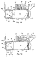
- FIGS. 1A and 1B depict cross-sectional views of a battery compartment 12 of an electrical device 10.
- the battery compartment 12 of the electrical device 10 is configurable to accommodate either a DL123 battery or an AA battery.
- the electrical device 10 may be, for example, night vision goggles, a camera flash, a portable audio device, a portable video game or a computer.
- the battery compartment 12 generally comprises a battery casing 16 including a substantially cylindrical recess 18 for at least partially encapsulating a battery (not shown), and a removable cover 30 for encapsulating the recess 18.
- the recess 18 includes an open end 20 for receiving a battery and a closed end 22 that is disposed opposite the open end 20.
- a first electrical contact element 24 is positioned on or adjacent the closed end 20 of the recess 18 for contacting a positive terminal of a battery (not shown).
- a second electrical contact element 14 is positioned on an interior surface of the cover 30 for contacting a negative terminal of a battery (not shown).
- the battery compartment 12 is the substantially cylindrical space defined between the first and second electrical contact elements 24 and 14, respectively.
- a battery is positioned within the substantially cylindrical space between the first and second electrical contact elements 24 and 14, respectively.
- the first electrical contact element 24 is electrically coupled to circuitry 26 of the electrical device 10 for distributing electrical power to the electrical device 10.
- the circuitry 26 may optionally include printed circuit boards 27 and 31 that are electrically interconnected by flex circuitry 29.
- the printed circuit board 31 is electrically connected to contact element 24, and printed circuit board 27 (or a conductive element) distributes electrical power to the electrical device 10.
- the first electrical contact element 24 is optionally fixed to the printed circuit board 31, and incapable of movement.
- the contact element 24 is optionally a leaf spring.
- contact element 24 may be made from a flexible, electrically conducting material such as Beryllium Copper (BeCu) alloy.
- contact element 24 may be formed from any other conductive metal or metal alloy.
- a coil spring may be used in lieu of a leaf spring.
- An open-ended cylindrical cover 30 is configured to be releasably mounted to the open end 20 of the recess 18 for selectively concealing the open end 20 and defining the battery compartment 12. In a closed position of the cover 30, as shown, a battery (not shown) is completely encapsulated within the battery compartment 12.
- the cover 30 includes a threaded region 32 disposed on an outer surface thereof for releasably engaging a threaded region 34 disposed on the open end 20 of the recess 18 of the battery casing 16.
- cover 30 may be releasably engaged with battery casing 16 in a variety of different fashions without departing from the scope or spirit of the invention.
- a second electrical contact element 14 is selectively positionable within the interior recess of the cover 30 for contacting an opposing terminal (e.g., negative terminal) of a battery. It follows that the interior surfaces of the cover 30 and the recess 18 of the battery casing 16 are electrically conductive to conduct electrical current from the battery terminal to circuitry 26.
- the contact element 14 is located in a first position to accommodate a DL123 battery (not shown).
- FIG. 1B depicts the contact element 14 located in a second position to accommodate a double-'A' (i.e., 'AA') battery (not shown).
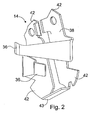
- FIG. 2 depicts a perspective view of the contact element 14 of FIGS. 1A and 1B .
- the contact element 14 is a snap ring.
- the contact element 14 optionally includes two prongs 36 for compressively contacting the terminal of a battery (e.g., negative terminal)).
- the prongs 36 may provide a compressible distance to stabilize a battery within the battery compartment 12.
- the prongs 36 extend from a substantially cylindrical base portion 38.
- the base portion 38 includes one or more engagement portions 42 for selectively positioning along the interior surface of the cover 30, as described in greater detail later.
- Each engagement portion 42 may be a tab, as shown, or any other structure sized for engagement with the cover 30.
- a bent segment 43 of the base portion 38 is provided to enhance the structural integrity of contact element 14.
- contact element 14 is a unitary component formed from a flexible, electrically conductive material such as Beryllium Copper (BeCu) alloy.
- contact element 14 may be formed from any other conductive metal or metal alloy that is sufficiently elastic to permit positioning, removal, and repositioning of contact element 14 along the interior surface of the cover 30.
- a coil spring or a leaf spring may be used in lieu of a snap ring.
- the contact element 14 is selectively and manually positionable at multiple locations on the cover 30 for adjusting the size of the battery compartment 12 to accommodate batteries of varying size. More particularly, the second electrical contact element 14 is selectively and manually positionable between a first position (see FIG. 1A ) for accommodating a 'DL123' battery within the battery compartment 12, and a second position (see FIG. 1 B) for accommodating a 'AA' battery within the battery compartment 12.
- the cover 30 includes a plurality of means for receiving 40a and 40b (referred to as 'means for receiving 40' collectively) the second electrical contact element 14.
- Each means for receiving 40 is positioned at a discrete location on the cover 30 and configured to independently receive the second electrical contact element 14. Adjacent means for receiving 40 are separated by a predetermined distance "D" (see FIG. 1B ).
- each means for receiving 40 the second electrical contact element 14 is a groove 40 formed about the interior circumference of the cover 30.
- the grooves 40 may be formed along all or a portion of the interior circumference of the cover 30.
- Each groove 40 is sized to independently receive the engagement portions 42 of second electrical contact element 14.
- the means for receiving 40 may also be a pin, slot, detent, channel, sleeve, thread, magnet, fastener, adhesive, spring, surface, or any other structure, surface or geometry capable of receiving and retaining the contact element 14.
- the cover 30 may include any number of means for receiving 40 for accommodating more than two battery sizes.
- a standard double-A (i.e., AA) battery manufactured according to ANSI specification 15A and IEC specification LR6, includes a substantially cylindrical body having a diameter of about 14.0 millimeters, and a length of about 40 millimeters.
- a standard DL123 battery manufactured in accordance with ANSI specification 5018LC and IEC specification CR17345, includes a substantially cylindrical body having a diameter of about 16.5 millimeters, and a length of about 34 millimeters.
- the length of the AA battery is about 6 millimeters greater than the length of the DL123 battery. Accordingly, the distance "D" separating the adjacent grooves 40 may be about 6 millimeters, and the total length of the battery compartment 12 (including the interior portion of the cover 30) should be greater than about 40 millimeters. Furthermore, the diameter of a DL123 battery is about 2.5 millimeters greater than the diameter of a AA battery. Accordingly, the interior diameter of the recess 18 of the battery casing 16 may be greater than about 16.5 millimeters to accommodate either a AA battery or a DL123 battery. It should be understood that this invention is not limited to any specific dimensions, and may vary from that described herein.
- the battery compartment 12 is not limited to accommodating either AA or DL123 batteries.
- the shape and size and the battery compartment may vary to accommodate any other battery sizes.
- the battery compartment is not limited to accommodating a single battery, and may accommodate any number of batteries.
- the electrical device 10 may include a plurality of battery compartments 12, moveable electrical contacts 14 and covers 30.
- a method of altering the size of a battery compartment of a battery-powered electrical device 10 includes the step of removing a contact element 14 that is configured for contacting the terminal of a battery from a first groove 40a formed along the interior circumference of the cover 30.
- the contact element 14 is then positioned in a second groove 40b that is formed along the interior circumference of the cover and separated from the first groove 40a.
- the contact element 14 is removed from the second groove 40b formed along the interior circumference of the cover 30.
- the contact element 14 is positioned in the first groove 40a formed in the cover 30.
- Each positioning step optionally includes the step of engaging a tab 42 of the electrical contact element 14 into a groove 40a or 40b of the cover 30. It should be understood that the foregoing steps are not limited to any step or sequence of steps.
- the moveable contact element may reside in the recess of the battery casing and the fixed contact element may reside in the cover of the battery compartment.
Landscapes
- Chemical & Material Sciences (AREA)
- Chemical Kinetics & Catalysis (AREA)
- Electrochemistry (AREA)
- General Chemical & Material Sciences (AREA)
- Battery Mounting, Suspending (AREA)
- Connection Of Batteries Or Terminals (AREA)
Abstract
Description
- The present invention relates to an expandable battery compartment for accommodating multiple battery sizes.
- The invention relates to battery powered electrical equipment, and in particular the invention is concerned with a battery compartment for a battery powered electrical device that accommodates different types of batteries having different exterior dimensions. Conventional portable electrical or electronic devices such as night vision goggles, camera flashes, tape recorders, games and computers are typically powered by standard dry cell batteries, such as alkaline type battery cells of standard dimensions.
- It has been a limitation of many conventional battery compartments of portable electrical devices in general, that a particular battery compartment could accommodate a battery or batteries of one particular size. It would therefore be desirable in a great number of portable devices for a battery compartment to be configured for receiving batteries of multiple sizes. In this way, a user could populate the portable electrical device with a wider variety of batteries.
- According to an aspect of the invention, an expandable battery compartment of an electrical device for accommodating batteries of varying size is provided. The battery compartment includes a battery casing defining a substantially cylindrical recess for at least partially encapsulating a battery. The recess has an open end for receiving a battery and a closed end. A first electrical contact element is positioned on or adjacent the closed end of the recess for contacting a terminal of a battery. The first electrical contact is electrically coupled to circuitry of the electrical device. A cover is configured to be releasably mounted to the open end of the recess for selectively concealing the open end and defining the battery compartment. A second electrical contact element is provided for contacting an opposing terminal of the battery. The second electrical contact element is selectively positionable at multiple locations on the cover to accommodate batteries of varying size within the battery compartment.
- Preferably a plurality of means are positioned on the cover for receiving the second electrical contact element, wherein each means for receiving is positioned at a discrete location on the cover and configured to independently receive the second electrical contact element to accommodate batteries of varying size within the battery compartment.
- According to yet another aspect of the invention, a method of altering the size of the battery compartment is provided. The method comprises the step of removing an electrical contact element that is configured for contacting a battery terminal from a first groove formed along the interior circumference of the cover. The electrical contact element is then positioned in a second groove that is formed along the interior circumference of the cover and separated from the first groove.
- The invention is best understood from the following detailed description when read in connection with the accompanying drawing. It is emphasized that, according to common practice, the various features of the drawing are not to scale. Included in the drawing are the following figures:
- FIG. 1A
- depicts a cross-sectional view of a battery compartment of an electrical device, according to one aspect of the invention, wherein a contact element is located in a first position to accommodate a DL123 battery.
- FIG. 1B
- depicts the battery compartment of
FIG. 1A wherein the contact element is located in a second position to accommodate a double-'A' (i.e., 'AA') battery. - FIG. 2
- depicts a perspective view of the contact element of
FIGS. 1A and 1B . - This invention will now be described with reference to several embodiments selected for illustration in the drawings. It will be appreciated that the scope and spirit of the invention are not limited to the illustrated embodiments.
- Referring generally to the figures, according to an aspect of the invention, an
expandable battery compartment 12 of anelectrical device 10 for accommodating batteries of varying size is provided. Thebattery compartment 12 includes abattery casing 16 defining a substantiallycylindrical recess 18 for at least partially encapsulating a battery. Therecess 18 has anopen end 20 for receiving a battery and a closedend 22 opposite theopen end 20. A firstelectrical contact element 24 is positioned on or adjacent the closedend 22 of therecess 18 for contacting a terminal of a battery. The firstelectrical contact 24 is electrically coupled tocircuitry 26 of theelectrical device 10. Acover 30 is configured to be releasably mounted to theopen end 20 of therecess 18 for selectively concealing theopen end 20 and defining thebattery compartment 12. A secondelectrical contact element 14 is provided for contacting an opposing terminal of the battery. The secondelectrical contact element 14 is selectively positionable atmultiple locations cover 30 to accommodate batteries of varying size within thebattery compartment 12. - According to another aspect of the invention, a plurality of
means cover 30 for receiving the secondelectrical contact element 14, wherein each means for receiving 40a, 40b is positioned at a discrete location on thecover 30 and configured to independently receive the secondelectrical contact element 14 to accommodate batteries of varying size within thebattery compartment 12. - According to yet another aspect of the invention, a method of altering the size of the
battery compartment 12 is provided. The method comprises the step of removing anelectrical contact element 14 that is configured for contacting a battery terminal from afirst groove 40a formed along the interior circumference of thecover 30. Theelectrical contact element 14 is then positioned in asecond groove 40b that is formed along the interior circumference of thecover 30 and separated from thefirst groove 40a. -
FIGS. 1A and 1B depict cross-sectional views of abattery compartment 12 of anelectrical device 10. Thebattery compartment 12 of theelectrical device 10 is configurable to accommodate either a DL123 battery or an AA battery. Theelectrical device 10 may be, for example, night vision goggles, a camera flash, a portable audio device, a portable video game or a computer. - The
battery compartment 12 generally comprises abattery casing 16 including a substantiallycylindrical recess 18 for at least partially encapsulating a battery (not shown), and aremovable cover 30 for encapsulating therecess 18. Therecess 18 includes anopen end 20 for receiving a battery and a closedend 22 that is disposed opposite theopen end 20. A firstelectrical contact element 24 is positioned on or adjacent the closedend 20 of therecess 18 for contacting a positive terminal of a battery (not shown). A secondelectrical contact element 14 is positioned on an interior surface of thecover 30 for contacting a negative terminal of a battery (not shown). Thebattery compartment 12 is the substantially cylindrical space defined between the first and secondelectrical contact elements electrical contact elements - The first
electrical contact element 24 is electrically coupled tocircuitry 26 of theelectrical device 10 for distributing electrical power to theelectrical device 10. Thecircuitry 26 may optionally includeprinted circuit boards flex circuitry 29. The printedcircuit board 31 is electrically connected tocontact element 24, and printed circuit board 27 (or a conductive element) distributes electrical power to theelectrical device 10. The firstelectrical contact element 24 is optionally fixed to the printedcircuit board 31, and incapable of movement. - The
contact element 24 is optionally a leaf spring. In an exemplary embodiment,contact element 24 may be made from a flexible, electrically conducting material such as Beryllium Copper (BeCu) alloy. In an alternative embodiment,contact element 24 may be formed from any other conductive metal or metal alloy. In another alternative embodiment, a coil spring may be used in lieu of a leaf spring. - An open-ended
cylindrical cover 30 is configured to be releasably mounted to theopen end 20 of therecess 18 for selectively concealing theopen end 20 and defining thebattery compartment 12. In a closed position of thecover 30, as shown, a battery (not shown) is completely encapsulated within thebattery compartment 12. - The
cover 30 includes a threadedregion 32 disposed on an outer surface thereof for releasably engaging a threadedregion 34 disposed on theopen end 20 of therecess 18 of thebattery casing 16. Those skilled in the art will recognize thatcover 30 may be releasably engaged withbattery casing 16 in a variety of different fashions without departing from the scope or spirit of the invention. - A second
electrical contact element 14 is selectively positionable within the interior recess of thecover 30 for contacting an opposing terminal (e.g., negative terminal) of a battery. It follows that the interior surfaces of thecover 30 and therecess 18 of thebattery casing 16 are electrically conductive to conduct electrical current from the battery terminal tocircuitry 26. InFIG. 1A , thecontact element 14 is located in a first position to accommodate a DL123 battery (not shown).FIG. 1B depicts thecontact element 14 located in a second position to accommodate a double-'A' (i.e., 'AA') battery (not shown). -
FIG. 2 depicts a perspective view of thecontact element 14 ofFIGS. 1A and 1B . According to one aspect of the invention, thecontact element 14 is a snap ring. Thecontact element 14 optionally includes twoprongs 36 for compressively contacting the terminal of a battery (e.g., negative terminal)). Theprongs 36 may provide a compressible distance to stabilize a battery within thebattery compartment 12. Theprongs 36 extend from a substantiallycylindrical base portion 38. Thebase portion 38 includes one ormore engagement portions 42 for selectively positioning along the interior surface of thecover 30, as described in greater detail later. Eachengagement portion 42 may be a tab, as shown, or any other structure sized for engagement with thecover 30. Abent segment 43 of thebase portion 38 is provided to enhance the structural integrity ofcontact element 14. - In an exemplary embodiment,
contact element 14 is a unitary component formed from a flexible, electrically conductive material such as Beryllium Copper (BeCu) alloy. In an alternative embodiment,contact element 14 may be formed from any other conductive metal or metal alloy that is sufficiently elastic to permit positioning, removal, and repositioning ofcontact element 14 along the interior surface of thecover 30. In another alternative embodiment, a coil spring or a leaf spring may be used in lieu of a snap ring. - Referring now to
FIGS. 1A, 1B and2 , thecontact element 14 is selectively and manually positionable at multiple locations on thecover 30 for adjusting the size of thebattery compartment 12 to accommodate batteries of varying size. More particularly, the secondelectrical contact element 14 is selectively and manually positionable between a first position (seeFIG. 1A ) for accommodating a 'DL123' battery within thebattery compartment 12, and a second position (seeFIG. 1 B) for accommodating a 'AA' battery within thebattery compartment 12. - The
cover 30 includes a plurality of means for receiving 40a and 40b (referred to as 'means for receiving 40' collectively) the secondelectrical contact element 14. Each means for receiving 40 is positioned at a discrete location on thecover 30 and configured to independently receive the secondelectrical contact element 14. Adjacent means for receiving 40 are separated by a predetermined distance "D" (seeFIG. 1B ). - According to one aspect of the invention, each means for receiving 40 the second
electrical contact element 14 is a groove 40 formed about the interior circumference of thecover 30. The grooves 40 may be formed along all or a portion of the interior circumference of thecover 30. Each groove 40 is sized to independently receive theengagement portions 42 of secondelectrical contact element 14. The means for receiving 40 may also be a pin, slot, detent, channel, sleeve, thread, magnet, fastener, adhesive, spring, surface, or any other structure, surface or geometry capable of receiving and retaining thecontact element 14. Although only two means for receiving 40 are shown inFIGS. 1A and 1B , thecover 30 may include any number of means for receiving 40 for accommodating more than two battery sizes. - Although not shown, a standard double-A (i.e., AA) battery, manufactured according to ANSI specification 15A and IEC specification LR6, includes a substantially cylindrical body having a diameter of about 14.0 millimeters, and a length of about 40 millimeters. A standard DL123 battery, manufactured in accordance with ANSI specification 5018LC and IEC specification CR17345, includes a substantially cylindrical body having a diameter of about 16.5 millimeters, and a length of about 34 millimeters.
- The length of the AA battery is about 6 millimeters greater than the length of the DL123 battery. Accordingly, the distance "D" separating the adjacent grooves 40 may be about 6 millimeters, and the total length of the battery compartment 12 (including the interior portion of the cover 30) should be greater than about 40 millimeters. Furthermore, the diameter of a DL123 battery is about 2.5 millimeters greater than the diameter of a AA battery. Accordingly, the interior diameter of the
recess 18 of thebattery casing 16 may be greater than about 16.5 millimeters to accommodate either a AA battery or a DL123 battery. It should be understood that this invention is not limited to any specific dimensions, and may vary from that described herein. - Those skilled in the art will recognize that the
battery compartment 12 is not limited to accommodating either AA or DL123 batteries. The shape and size and the battery compartment may vary to accommodate any other battery sizes. Furthermore, the battery compartment is not limited to accommodating a single battery, and may accommodate any number of batteries. Accordingly, theelectrical device 10 may include a plurality ofbattery compartments 12, moveableelectrical contacts 14 and covers 30. - According to one exemplary use of the invention, a method of altering the size of a battery compartment of a battery-powered
electrical device 10 is provided. The method includes the step of removing acontact element 14 that is configured for contacting the terminal of a battery from afirst groove 40a formed along the interior circumference of thecover 30. Thecontact element 14 is then positioned in asecond groove 40b that is formed along the interior circumference of the cover and separated from thefirst groove 40a. Thecontact element 14 is removed from thesecond groove 40b formed along the interior circumference of thecover 30. Thecontact element 14 is positioned in thefirst groove 40a formed in thecover 30. Each positioning step optionally includes the step of engaging atab 42 of theelectrical contact element 14 into agroove cover 30. It should be understood that the foregoing steps are not limited to any step or sequence of steps. - Although the invention is illustrated and described herein with reference to specific embodiments, the invention is not intended to be limited to the details shown. Rather, various modifications may be made in the details within the scope and range of equivalents of the claims and without departing from the spirit of the invention. For example, the moveable contact element may reside in the recess of the battery casing and the fixed contact element may reside in the cover of the battery compartment.
Claims (11)
- In a battery-powered electrical device (10), an expandable battery compartment (12) for accommodating batteries of varying size, said battery compartment comprising:a battery casing (16) defining a substantially cylindrical recess (18) for at least partially encapsulating a battery, said recess having an open end (20) for receiving a battery and a closed end (22);a first electrical contact element (24) positioned on or adjacent the closed end (22) of the recess for contacting a terminal of a battery, said first electrical contact being electrically coupled to circuitry (26) of the electrical device;a cover (30) configured to be releasably mounted to the open end (20) of the recess for selectively concealing the open end and defining the battery compartment (12); anda second electrical contact element (14) for contacting an opposing terminal of the battery, said second electrical contact element (14) being selectively positionable at multiple locations (40a, 40b) on the cover to accommodate batteries of varying size within the battery compartment.
- In a battery-powered electrical device (10), an expandable battery compartment (12) for accommodating batteries of varying size, said battery compartment comprising:a battery casing (16) defining a substantially cylindrical recess (18) for at least partially encapsulating a battery, said recess having an open end (20) for receiving a battery and a closed end (22);a first electrical contact element (24) positioned on or adjacent the closed end (22) of the recess for contacting a terminal of a battery, said first electrical contact being electrically coupled to circuitry (26) of the electrical device;a cover (30) configured to be releasably mounted to the open end (20) of the recess for selectively concealing the open end and defining the battery compartment (12);a second electrical contact element (14) for contacting an opposing terminal of the battery; and a plurality of means (40a, 40b) positioned on the cover for receiving the second electrical contact element (14), wherein each means (40a, 40b) for receiving is positioned at a discrete location on the cover (30) and configured to independently receive the second electrical contact (14) element to accommodate batteries of varying size within the battery compartment.
- The battery compartment (12) of claim 1, said cover (30) comprising a plurality of means (40a, 40b) for receiving the second electrical contact element, wherein each means for receiving is positioned at a discrete location on the cover (30) and configured to independently receive the second electrical contact element.
- The battery compartment (12) of claim 1 or 2, wherein adjacent means (40a, 40b) for receiving are separated by a predetermined distance (D).
- The battery compartment (12) of at least one of claims 1 to 4, wherein each means (40a, 40b) for receiving the second electrical contact element (14) is a groove formed about the interior circumference of the cover (30), each groove being sized to independently receive the second electrical contact element (14).
- The battery compartment (12) of claim 5, said second electrical contact element (14) including an engagement portion (42) sized for insertion into a single groove formed in the cover.
- The battery compartment (12) of at least one of claims 1 to 6, wherein the second electrical contact element (14) is selectively positionable between a first position (40a) for accommodating a 'DL123' battery within the battery compartment, and a second position (40b) for accommodating a 'AA' battery within the battery compartment.
- The battery compartment of at least one of claims 1 to 7 further comprising a threaded region (32) disposed on the cover for releasably engaging a threaded region (34) disposed on the open end of the recess of the battery casing.
- In a battery-powered electrical device (10) including a battery casing (12) defining a substantially cylindrical recess (18) for at least partially encapsulating a battery, and a cover (30) configured to be releasably mounted to an open end (20) of the recess, a method of altering the size of the battery compartment comprising the steps of:removing an electrical contact element (14) that is configured for contacting a battery terminal from a first groove (40a) formed along the interior circumference of the cover; andpositioning the electrical contact element (14) in a second groove (40b) that is formed along the interior circumference of the cover and separated from the first groove.
- The method of claim 9 further comprising the steps of:removing the electrical contact element (14) from the second groove (40b) formed along the interior circumference of the cover; andpositioning the electrical contact element (14) in the first groove (40a) formed in the cover.
- The method of claim 9 or 10, wherein the positioning step comprises engaging a tab (42) of the electrical contact element into the first or second groove (40a, 40b) of the cover.
Applications Claiming Priority (1)
| Application Number | Priority Date | Filing Date | Title |
|---|---|---|---|
| US11/947,161 US7678500B2 (en) | 2007-11-29 | 2007-11-29 | Expandable battery compartment |
Publications (2)
| Publication Number | Publication Date |
|---|---|
| EP2065951A2 true EP2065951A2 (en) | 2009-06-03 |
| EP2065951A3 EP2065951A3 (en) | 2011-01-05 |
Family
ID=40459826
Family Applications (1)
| Application Number | Title | Priority Date | Filing Date |
|---|---|---|---|
| EP08170057A Withdrawn EP2065951A3 (en) | 2007-11-29 | 2008-11-27 | Expandable Battery Compartment |
Country Status (8)
| Country | Link |
|---|---|
| US (1) | US7678500B2 (en) |
| EP (1) | EP2065951A3 (en) |
| KR (1) | KR101560590B1 (en) |
| AU (1) | AU2008203826B2 (en) |
| CA (1) | CA2639628A1 (en) |
| IL (1) | IL192672A (en) |
| NO (1) | NO20084981L (en) |
| SG (1) | SG152976A1 (en) |
Families Citing this family (4)
| Publication number | Priority date | Publication date | Assignee | Title |
|---|---|---|---|---|
| US9954205B2 (en) | 2016-04-12 | 2018-04-24 | Energizer Brands, Llc | Slotted battery cavity for multiple cell sizes |
| US11196119B2 (en) | 2018-09-26 | 2021-12-07 | Techtronic Cordless Gp | Collapsible cover for a battery pack |
| KR102587977B1 (en) | 2019-01-28 | 2023-10-11 | (주)세자에너지 | Battery for forward and reverse rotation of a motor, and charging system thereof |
| WO2020250087A1 (en) | 2019-06-10 | 2020-12-17 | 3M Innovative Properties Company | Adapter for battery compartment |
Family Cites Families (10)
| Publication number | Priority date | Publication date | Assignee | Title |
|---|---|---|---|---|
| US3089072A (en) * | 1958-10-06 | 1963-05-07 | Longworth Scient Instr Company | Rechargeable electric battery unit |
| US5015546A (en) * | 1989-06-12 | 1991-05-14 | Grid Systems Corporation | Battery compartment |
| US5395263A (en) * | 1993-03-24 | 1995-03-07 | C & K Systems, Inc. | Dual battery holder |
| DE19715545B4 (en) * | 1997-04-15 | 2010-07-01 | Sennheiser Electronic Gmbh & Co. Kg | Battery compartment, microphone and electronic device |
| US7049027B2 (en) * | 2003-02-05 | 2006-05-23 | Itt Manufacturing Enterprises, Inc. | Single battery housing assembly |
| US20040202927A1 (en) * | 2003-04-12 | 2004-10-14 | Drea Sandra L | Cell spacer for a battery pack |
| US7454858B2 (en) * | 2003-08-05 | 2008-11-25 | R/M Equipment, Inc. | Weapon grip assembly |
| US6942359B2 (en) * | 2003-12-08 | 2005-09-13 | Eveready Battery Company, Inc. | Flashlight that can operate with alternative size batteries |
| US6971333B1 (en) * | 2005-01-25 | 2005-12-06 | Hearrell Chad E | Adjustable animal kennel |
| US7687197B2 (en) * | 2005-10-07 | 2010-03-30 | Research In Motion Limited | Expandable battery compartment for handheld electronic devices |
-
2007
- 2007-11-29 US US11/947,161 patent/US7678500B2/en active Active
-
2008
- 2008-07-07 IL IL192672A patent/IL192672A/en not_active IP Right Cessation
- 2008-08-12 AU AU2008203826A patent/AU2008203826B2/en not_active Ceased
- 2008-09-18 CA CA002639628A patent/CA2639628A1/en not_active Abandoned
- 2008-09-26 SG SG200807215-9A patent/SG152976A1/en unknown
- 2008-11-27 EP EP08170057A patent/EP2065951A3/en not_active Withdrawn
- 2008-11-28 KR KR1020080120023A patent/KR101560590B1/en not_active Expired - Fee Related
- 2008-11-28 NO NO20084981A patent/NO20084981L/en not_active Application Discontinuation
Also Published As
| Publication number | Publication date |
|---|---|
| US7678500B2 (en) | 2010-03-16 |
| EP2065951A3 (en) | 2011-01-05 |
| KR101560590B1 (en) | 2015-10-16 |
| IL192672A (en) | 2013-05-30 |
| KR20090056912A (en) | 2009-06-03 |
| SG152976A1 (en) | 2009-06-29 |
| IL192672A0 (en) | 2009-02-11 |
| AU2008203826B2 (en) | 2012-08-30 |
| CA2639628A1 (en) | 2009-05-29 |
| US20090142652A1 (en) | 2009-06-04 |
| NO20084981L (en) | 2009-06-02 |
| AU2008203826A1 (en) | 2009-06-18 |
Similar Documents
| Publication | Publication Date | Title |
|---|---|---|
| US11239668B2 (en) | Charger case for wearable electronics | |
| RU2212768C2 (en) | Portable telephone set with changeable battery | |
| CN109923728B (en) | Reusable battery indicator with detent mechanism | |
| US7901221B1 (en) | Universal serial bus ground clip | |
| CN107834305B (en) | Charging equipment and electronic devices | |
| US10057695B2 (en) | Hearing aid battery door module | |
| US9005057B2 (en) | Apparatus, system and method for electronic archery devices | |
| US7678500B2 (en) | Expandable battery compartment | |
| US8203844B2 (en) | Electronic device with back-up power supply | |
| US20240339677A1 (en) | Rechargeable lithium battery assembly | |
| US6022248A (en) | Connecting terminal having enhanced biasing force | |
| US20090033286A1 (en) | Cell and Supercapacitor Battery Pack | |
| WO2010022142A1 (en) | Battery retainer | |
| GB2260040A (en) | Battery charger | |
| EP0279903A2 (en) | Construction of battery compartment | |
| US20070293082A1 (en) | Terminal assembly for selectively coupling loads in parallel and in series | |
| EP1498988B1 (en) | Connector | |
| CA2731217A1 (en) | Universal battery charger | |
| CN223141131U (en) | Charging wire module and combined charging device | |
| JPH11339741A (en) | Portable equipment | |
| US20240363938A1 (en) | Battery Holder | |
| US9293863B2 (en) | Mountable open top connector having a retainer | |
| JP2000299172A (en) | Connector device | |
| CN223157371U (en) | Card type intelligent tracker | |
| JP2645872B2 (en) | Charger |
Legal Events
| Date | Code | Title | Description |
|---|---|---|---|
| PUAI | Public reference made under article 153(3) epc to a published international application that has entered the european phase |
Free format text: ORIGINAL CODE: 0009012 |
|
| AK | Designated contracting states |
Kind code of ref document: A2 Designated state(s): AT BE BG CH CY CZ DE DK EE ES FI FR GB GR HR HU IE IS IT LI LT LU LV MC MT NL NO PL PT RO SE SI SK TR |
|
| AX | Request for extension of the european patent |
Extension state: AL BA MK RS |
|
| PUAL | Search report despatched |
Free format text: ORIGINAL CODE: 0009013 |
|
| AK | Designated contracting states |
Kind code of ref document: A3 Designated state(s): AT BE BG CH CY CZ DE DK EE ES FI FR GB GR HR HU IE IS IT LI LT LU LV MC MT NL NO PL PT RO SE SI SK TR |
|
| AX | Request for extension of the european patent |
Extension state: AL BA MK RS |
|
| 17P | Request for examination filed |
Effective date: 20110705 |
|
| AKX | Designation fees paid |
Designated state(s): DE FR GB |
|
| RAP1 | Party data changed (applicant data changed or rights of an application transferred) |
Owner name: EXELIS INC. |
|
| STAA | Information on the status of an ep patent application or granted ep patent |
Free format text: STATUS: THE APPLICATION IS DEEMED TO BE WITHDRAWN |
|
| 18D | Application deemed to be withdrawn |
Effective date: 20130601 |