EP2065765A1 - Image forming apparatus - Google Patents
Image forming apparatus Download PDFInfo
- Publication number
- EP2065765A1 EP2065765A1 EP08170138A EP08170138A EP2065765A1 EP 2065765 A1 EP2065765 A1 EP 2065765A1 EP 08170138 A EP08170138 A EP 08170138A EP 08170138 A EP08170138 A EP 08170138A EP 2065765 A1 EP2065765 A1 EP 2065765A1
- Authority
- EP
- European Patent Office
- Prior art keywords
- image forming
- forming apparatus
- data
- temperature
- unit
- Prior art date
- Legal status (The legal status is an assumption and is not a legal conclusion. Google has not performed a legal analysis and makes no representation as to the accuracy of the status listed.)
- Granted
Links
- 238000001514 detection method Methods 0.000 claims abstract description 44
- 238000003860 storage Methods 0.000 claims abstract description 36
- 238000001816 cooling Methods 0.000 claims abstract 11
- 238000004891 communication Methods 0.000 claims description 31
- 238000012546 transfer Methods 0.000 description 36
- 238000012545 processing Methods 0.000 description 14
- 230000005540 biological transmission Effects 0.000 description 13
- 238000010586 diagram Methods 0.000 description 13
- 230000006870 function Effects 0.000 description 9
- 230000015572 biosynthetic process Effects 0.000 description 7
- 238000005755 formation reaction Methods 0.000 description 7
- 238000000034 method Methods 0.000 description 5
- 230000001105 regulatory effect Effects 0.000 description 5
- 238000004519 manufacturing process Methods 0.000 description 4
- 238000006243 chemical reaction Methods 0.000 description 3
- 238000007726 management method Methods 0.000 description 3
- 238000002844 melting Methods 0.000 description 3
- 230000008018 melting Effects 0.000 description 3
- 238000012544 monitoring process Methods 0.000 description 3
- 230000008859 change Effects 0.000 description 2
- 230000006835 compression Effects 0.000 description 2
- 238000007906 compression Methods 0.000 description 2
- 238000012423 maintenance Methods 0.000 description 2
- 238000005259 measurement Methods 0.000 description 2
- 230000008569 process Effects 0.000 description 2
- 230000004044 response Effects 0.000 description 2
- 238000000926 separation method Methods 0.000 description 2
- 239000003086 colorant Substances 0.000 description 1
- 230000001276 controlling effect Effects 0.000 description 1
- 238000012937 correction Methods 0.000 description 1
- 238000005520 cutting process Methods 0.000 description 1
- 230000003247 decreasing effect Effects 0.000 description 1
- 230000005684 electric field Effects 0.000 description 1
- 230000005611 electricity Effects 0.000 description 1
- 229910052736 halogen Inorganic materials 0.000 description 1
- 150000002367 halogens Chemical class 0.000 description 1
- 238000012986 modification Methods 0.000 description 1
- 230000004048 modification Effects 0.000 description 1
- 238000006386 neutralization reaction Methods 0.000 description 1
- 238000003825 pressing Methods 0.000 description 1
Images










Classifications
-
- G—PHYSICS
- G03—PHOTOGRAPHY; CINEMATOGRAPHY; ANALOGOUS TECHNIQUES USING WAVES OTHER THAN OPTICAL WAVES; ELECTROGRAPHY; HOLOGRAPHY
- G03G—ELECTROGRAPHY; ELECTROPHOTOGRAPHY; MAGNETOGRAPHY
- G03G21/00—Arrangements not provided for by groups G03G13/00 - G03G19/00, e.g. cleaning, elimination of residual charge
- G03G21/20—Humidity or temperature control also ozone evacuation; Internal apparatus environment control
-
- G—PHYSICS
- G03—PHOTOGRAPHY; CINEMATOGRAPHY; ANALOGOUS TECHNIQUES USING WAVES OTHER THAN OPTICAL WAVES; ELECTROGRAPHY; HOLOGRAPHY
- G03G—ELECTROGRAPHY; ELECTROPHOTOGRAPHY; MAGNETOGRAPHY
- G03G15/00—Apparatus for electrographic processes using a charge pattern
- G03G15/06—Apparatus for electrographic processes using a charge pattern for developing
- G03G15/08—Apparatus for electrographic processes using a charge pattern for developing using a solid developer, e.g. powder developer
- G03G15/0822—Arrangements for preparing, mixing, supplying or dispensing developer
- G03G15/0863—Arrangements for preparing, mixing, supplying or dispensing developer provided with identifying means or means for storing process- or use parameters, e.g. an electronic memory
-
- G—PHYSICS
- G03—PHOTOGRAPHY; CINEMATOGRAPHY; ANALOGOUS TECHNIQUES USING WAVES OTHER THAN OPTICAL WAVES; ELECTROGRAPHY; HOLOGRAPHY
- G03G—ELECTROGRAPHY; ELECTROPHOTOGRAPHY; MAGNETOGRAPHY
- G03G2215/00—Apparatus for electrophotographic processes
- G03G2215/06—Developing structures, details
- G03G2215/066—Toner cartridge or other attachable and detachable container for supplying developer material to replace the used material
- G03G2215/0695—Toner cartridge or other attachable and detachable container for supplying developer material to replace the used material using identification means or means for storing process or use parameters
-
- G—PHYSICS
- G03—PHOTOGRAPHY; CINEMATOGRAPHY; ANALOGOUS TECHNIQUES USING WAVES OTHER THAN OPTICAL WAVES; ELECTROGRAPHY; HOLOGRAPHY
- G03G—ELECTROGRAPHY; ELECTROPHOTOGRAPHY; MAGNETOGRAPHY
- G03G2221/00—Processes not provided for by group G03G2215/00, e.g. cleaning or residual charge elimination
- G03G2221/16—Mechanical means for facilitating the maintenance of the apparatus, e.g. modular arrangements and complete machine concepts
- G03G2221/18—Cartridge systems
- G03G2221/1815—Cartridge systems for cleaning or developing but not being a process cartridge
Definitions
- the present invention relates to an image forming apparatus to which a developer storage container having a function of communicating with the image forming apparatus can be detachably mounted.
- Japanese Patent Laid-Open No. 2003-263022 proposes the following technique. Change in temperature from production of the toner cartridge to delivery to a user and also in a storage environment is stored as temperature history information.
- a period of time for conducting a toner agitating control is changed on the basis of the temperature history information.
- This technique is for changing the agitating time in accordance with a toner condition because the concentration rate of the toner is varied depending on the toner storage condition.
- a temperature sensor arranged to detect temperature change up to until the toner cartridge is delivered to the user is provided, but this temperature sensor is not effectively utilized after the toner cartridge is mounted to the image forming apparatus.
- the environment control such as the temperature control for the inside of the image forming apparatus or the air flow control for the inside of the image forming apparatus cannot be performed by using the temperature sensor inside the toner cartridge.
- the present invention provides an image forming apparatus as specified in claims 1 to 8.
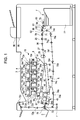
- Fig. 1 is a vertical cross-sectional view of a schematic configuration of an image forming apparatus according to an embodiment of the present invention.
- Fig. 2 is another vertical cross-sectional view of a schematic configuration of the image forming apparatus.
- Fig. 3 illustrates a relation between a detected temperature and the number of rotations of a fan to be controlled.
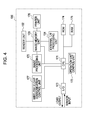
- Fig. 4 is a block diagram of a control unit of the image forming apparatus.
- Fig. 5 is a block diagram of an image memory unit of the image forming apparatus.
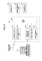
- Fig. 6 is a block diagram of an external I/F processing unit of the image forming apparatus.
- Fig. 7 is a block diagram of a wireless IC chip communication control unit.
- Fig. 8 is a block diagram of a wireless IC chip unit.
- Fig. 9 illustrates an operation unit provided to the image forming apparatus.
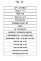
- Fig. 10 illustrates an example of data structure stored in the wireless IC chip unit.
- Fig. 11 is an explanatory diagram of data indicating on which face of a toner CRG a temperature sensor is arranged.
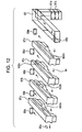
- Fig. 12 is an explanatory diagram of an arrangement example of the temperature sensors provided to the wireless IC chip units of the toner CRGs.
- Fig. 13 is a flowchart for describing a monitoring operation of the toner CRG provided outside the image forming apparatus.
- Fig. 14 illustrates a message example displayed on the operation unit in a case where the temperature of the storage container for the toner CRG is too high.
- Fig. 15 is a flowchart for describing a control in a case where the toner CRG is mounted to the image forming apparatus.
- Fig. 16 is a structural drawing of a temperature sensor data table for storing data of the temperature sensor provided inside the image forming apparatus.
- Fig. 17 is a structural drawing of a temperature sensor data table for each fan provided inside the image forming apparatus.
- Fig. 18 is a flowchart for describing a control in a case where the toner CRG is detached from the image forming apparatus.
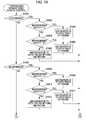
- Fig. 19 is a flowchart for describing an updating control on a temperature sensor table.
- Fig. 20 is a flowchart for describing the updating control on the temperature sensor table.
- Fig. 21 is a flowchart for describing a rotation control of a supply air fan.
- Fig. 22 is a flowchart for describing a rotation control of an exhaust air fan.
- Figs. 1 and 2 are cross-sectional views of an image forming apparatus 1 according to an embodiment of the present invention.
- the image forming apparatus 1 is composed of an image forming unit 10, a paper feed unit 7, an intermediate transfer unit 5, a fixing unit 40, an operation unit 4, a control unit 100 (refer to Fig. 4 ), and the like.
- photosensitive drums 11a, 11b, 11c, and 11d functioning as image bearing members are axially supported about the center thereof, and rotated and driven by a drive motor in an arrow direction.
- roller chargers 12a, 12b, 12c, and 12d While facing outer circumference surfaces of the photosensitive drums 11a to 11d, roller chargers 12a, 12b, 12c, and 12d, scanners 13a, 13b, 13c, and 13d, and developing apparatuses 14a, 14b, 14c, and 14d are arranged in a rotation direction thereof.
- the roller chargers 12a to 12d supply charges of a uniform electrification amount to surfaces of the photosensitive drums 11a to 11d.
- scanners 13a to 13d expose the photosensitive drums 11a to 11d to light beam such as laser beam modified in accordance with a recording image signal to form electrostatic latent images thereon.
- the developing apparatuses 14a to 14d respectively storing developer (toner) of four colors including yellow, cyan, magenta, and black visualize the above-described electrostatic latent images.
- the visualized image is transferred onto an intermediate transfer belt 30.
- toner cartridges (hereinafter, referred to as toner CRGs) 87a, 87b, 87c, and 87d functioning as developer storage containers are detachably mounted to the image forming apparatus 1.
- toner CRGs By replacing the toner CRGs by a user, it is possible to perform toner replenishment.
- toner CRG set detection sensors 15a, 15b, 15c, and 15d it is possible to detect whether the toner cartridges are mounted or not mounted.
- the developing apparatuses 14a, 14b, 14c, and 14d are provided with hoppers, it is possible to replenish the toner even while the developing apparatuses 14a, 14b, 14c, and 14d are operated.
- toner sensors provided inside the developing apparatuses 14a, 14b, 14c, and 14d detect that the toner is running out
- a toner conveying motor inside the hopper is operated to supply the toner inside the hopper into the developing apparatuses 14a, 14b, 14c, and 14d.
- the image forming unit 10 is provided with ducts 82 and 84 for supplying air from the outside into the inside of the image forming apparatus.
- the air from the outside is supplied through an air filter 83.
- the inside of the image forming apparatus is cooled down.
- Temperature sensors 85a and 85b functioning as a first temperature detection unit are arranged to detect a temperature of the inside of the image forming apparatus (in the ducts 82 and 84).
- Exhaust air fans 89a, 89b, 89c, 89d, and 89e are fans for exhausting air in the vicinity of the toner CRGs to the outside of the image forming apparatus. Also, in the exhaust air fans 89a, 89b, 89c, 89d, and 89e, the number of the rotations of the fan can be freely controlled in a predetermined range.
- Fig. 3 illustrates a relation between the detected temperature and the number of rotations of the fan.
- Data indicating the temperature and the number of rotations is stored in the control unit 100 as an individual data table for each fan.
- the control unit 100 is arranged to drive the fans on the basis of the detection results of the temperature sensors. Basically, such a control is performed that as the detected temperature is higher, the number of rotations of the fan is increased.
- the paper feed unit 7 is composed of a storage unit 77 for storing sheets P, rollers 60 and 61 for feeding the sheet P, a sensor 64 for checking feed of the sheet P, a sensor 66 for detecting passing of the sheet P, a sensor 75 for detecting the presence or absence of the sheet P, and the like.
- the pickup roller 60 is arranged to feed the sheet P from the storage unit 77 one each. In some cases, a plurality of the sheets P may be fed from the pickup roller 60, but the separation roller 61 is operated to separate the sheets P into one sheet.
- the sheet P separated into one sheet by the separation roller 61 is further conveyed to a pullout roller 62 and conveyed up to a pre-registration roller 78.
- the paper feed unit 7 can detect an interval distance of the sheets when the previously conveyed sheet P exists by detecting the trailing end of the previously conveyed sheet P and the leading end of the sheet P picked up next and fed with use of a sheet feed conveyance sensor 66. Then, a pickup operation is started so that the interval distance of the sheets is set as a predetermined distance previously determined in accordance with the conveyance speed.
- the sheet P is conveyed and the leading end of the sheet P is detected by a pre-registration sensor 22.
- conveying rollers 25, 26, and 27 are driven at a predetermined speed, and the sheet P is conveyed by the conveying rollers 25, 26, and 27.
- a registration sensor 21 detects the leading end of the sheet P
- the sheet P is conveyed at a predetermined distance, and the leading end of the sheet P abuts against a registration roller 29.
- the drive of the conveying rollers 25, 26, and 27 is stopped.
- the leading end of the sheet P abuts against the registration roller 29 at rest, and the leading end of the sheet P is regulated, so that skew is corrected.
- the registration roller 29 and the conveying rollers 25, 26, and 27 are driven again, and registration for the sheet P is performed at the position of the image already formed on the intermediate transfer belt 30.
- the registration roller 29 is stopped and ready for the next skew correction. Then, the sheet P is conveyed to the intermediate transfer unit 5.
- a driving roller 32 is a roller for transmitting a drive to the intermediate transfer belt 30, and rotated and driven by a stepping motor.
- a tension roller 33 is a roller for supplying an appropriate tensile force to the intermediate transfer belt 30 by way of bias of a spring. Driven rollers 34 are supported while sandwiching the intermediate transfer belt 30 so as to form a secondary transfer area.
- primary transfer rollers 35a to 35d are arranged on an opposite side of the intermediate transfer belt 30 at positions where the respective photosensitive drums 11a to 11d faces the intermediate transfer belt 30.
- the primary transfer rollers 35a to 35d are applied with a high voltage for transferring the toner image onto the intermediate transfer belt 30.
- a secondary transfer roller 45 for transferring the image on the intermediate transfer belt 30 onto the sheet P is arranged on a lower side of the intermediate transfer belt 30, a secondary transfer roller 45 for transferring the image on the intermediate transfer belt 30 onto the sheet P is arranged. With a nip between the secondary transfer roller 45 and the intermediate transfer belt 30, a secondary transfer area is formed. The secondary transfer roller 45 is pressed at an appropriate pressure against the intermediate transfer belt.
- a secondary transfer belt 46 which is an endless belt is supported between the secondary transfer roller 45 and a supporting roller 47 rotated and driven by a motor.
- the secondary transfer roller 45 abuts against the driven rollers 34 across the secondary transfer belt 46 and the intermediate transfer belt 30.
- the driven rollers 34 is applied with bias of the same polarity as a toner polarity by a power source. Also, the secondary transfer roller 45 is grounded, and a secondary transfer electric field is affected between the driven rollers 34 and the secondary transfer roller 45.
- the sheet P on which the toner image is transferred is borne on the secondary transfer belt 46 and conveyed. Then, the sheet P is subjected to removal of electricity due to discharge of a neutralization charger 48 and separated from the secondary transfer belt 46. Then, the sheet P is conveyed to the fixing unit 40.
- the fixing unit 40 includes a fixing roller 41a provided with a heat source such as a halogen heater inside thereof and a pressing roller 41b pressed by the roller.
- the toner image is fixed on the front face of the sheet P by the heat of the roller pair 41a and 41b and the pressure of the nip.
- the conveyance destination is switched by a flapper 73, and the sheet P is ejected to a paper output tray 2 by a roller 79 or ejected to a paper output tray 3 by the rollers 72a, 72b, and 72c.
- an inner paper output sensor 68 a face down paper output sensor 69, a duplex sensor 70a, a duplex pre-registration sensor 70b, a duplex refeeding sensor 70c, and the like are provided.
- an original feed apparatus 96 is an apparatus arranged to feed the set original onto a reading position of an image scanning apparatus 95. Then, image data of the original fed onto the reading position of the image scanning apparatus 95 is converted into image information by the image scanning apparatus 95.
- the image forming apparatus 1 On the basis of the image information of the read original image, the image forming apparatus 1 performs image formation on the sheet P, so that a copy function of the original image is realized.
- the operation unit 4 is used for the user to issue instructions about an image formation mode, the number of images to be formed, and an image formation condition, and for a service person to perform a maintenance work on the apparatus, for example.
- a start key on the operation unit 4 When a start key on the operation unit 4 is pressed, the reading operation for the original image is started, and also the image formation operation of the image forming apparatus 1 and other operations such as transmission of the original image are performed.
- Fig. 4 is a block diagram of the control unit 100 in the image forming apparatus 1 of Fig. 1 .
- a CPU 171 is a circuit arranged to perform a basic control of the image forming apparatus 1.
- the CPU 171 is connected to a ROM 174, a RAM 175, and an input output port 173 via an address bus and a data bus.
- ROM 174 a control program is written.
- the RAM 175 is composed of a non-volatile memory, and can store a storage content even when the power source is turned OFF.
- the input output port 173 is provided with functions for performing input and output controls at the port, an A/D or D/A conversion control, and the like. Also, to the input output port 173, a motor for controlling the image forming apparatus 1, various loads such as a clutch, a sensor for detecting a position of the sheet in the image forming apparatus, a temperature sensor for detecting a temperature, and the like are connected.
- the CPU 171 sequentially performs input and output controls via the input output port 173 to execute the image forming operation.
- an operation unit control unit 172 is connected to the CPU 171 and is arranged to control a display and a key input with respect to the operation unit 4.
- An operator perform the key input from the operation unit 4 to instruct the CPU 171 to perform display switching such as an image formation mode, a scanner reading mode, a print output mode, and setting for the sheet information.
- the CPU 171 performs the display of a state of the image forming apparatus 1 and the operation mode setting through the key input.
- an image processing unit 170 arranged to process the signal converted into the electric signal by the image scanning apparatus 95 and an image memory unit 103 arranged to accumulate the processed images are connected.
- an image memory unit 103 a reader unit 102 arranged to control the image scanning apparatus 95, a printer unit 176 arranged to control the image forming operation, and an external I/F processing unit 104 are connected.
- a wireless IC chip communication control unit 177 is connected to the CPU 171.
- the wireless IC chip communication control unit 177 is arranged to control a communication with a plurality of wireless IC chips.
- Fig. 5 is a block diagram of the image memory unit 103.
- a memory controller 302 is connected to a page memory 301 composed of a memory such as a DRAM.
- the memory controller 302 performs transmission and reception of the image data with the external I/F processing unit 104, the image processing unit 170, the reader unit 102, and the printer unit 176.
- a compression unit 303 compresses the image data received from the memory controller 302 into a JPG format or the like.
- the image data compressed by the compression unit 303 is stored in a hard disk drive 304 functioning as a large capacity storage apparatus.
- the memory controller 302 generates a DRAM refresh signal of the page memory 301. Also, the memory controller 302 controls accesses to the page memory 301 from the external I/F processing unit 104, the image processing unit 170, and the hard disk drive 304.
- the memory controller 302 performs controls on a write address to the page memory 301, a read address from the page memory 301, a read direction, and the like.
- the CPU 171 lays out the plurality of original images on the page memory 301 and controls a function for the output to the printer unit 176, a function of cutting only a part of the images for the output, and an image rotation function.
- External I/F processing unit
- Fig. 6 is a block diagram of the external I/F processing unit 104.
- the external I/F processing unit 104 takes in the image data of the reader unit 102 via the image memory unit 103. Also, the external I/F processing unit 104 outputs the image data via the image memory unit 103 to the printer unit 176.
- the external I/F processing unit 104 includes a core unit 406, a facsimile unit 401, a hard disc drive unit 402, a computer interface 403 connected to an external computer 411, a formatter unit 404, and an image memory unit 405.
- the facsimile unit 401 is connected via a modem to a public line and performs reception of facsimile communication data from the public line and transmission of facsimile communication data to the public line. In a case where the facsimile transmission is carried out at a specified time, the facsimile unit 401 saves the image for the facsimile in the hard disc drive unit 402 and performs the processing.
- the computer interface 403 is an interface for performing a data communication with an external computer and includes a local area network (hereinafter, referred to as LAN), a serial I/F, an SCSI I/F, Centronics I/F for data input for the printer, and the like.
- the computer interface 403 notifies the external computer 411 of the states of the printer unit 176 and the reader unit 102 and transfers the image read by the reader unit 102 to the external computer 411 in accordance with the instruction of the external computer 411. Also, the computer interface 403 performs the reception of the print image data from the external computer 411.
- the print data notified from the external computer 411 via the computer interface 403 is written in a dedicated use printer code.
- the formatter unit 404 converts the code into raster image data for performing the image formation in the printer unit 176.
- the formatter unit 404 opens up the raster image data.
- the image memory unit 405 is used as the memory for the formatter unit 404 to open up the raster image data, and used for transmitting the image of the reader unit 102 via the computer interface 403 to an external computer.
- the core unit 406 controls and manages data transfer among the facsimile unit 401, the computer interface 403, the formatter unit 404, the image memory unit 405, and the image memory unit 103. With this configuration, even when the external I/F processing unit 104 has a plurality of image output units or one image transfer path to the image memory unit 103 exists, under the management of the core unit 406, exclusive access control and priority control are conducted and the image output is performed.
- Fig. 7 is a block diagram of the wireless IC chip communication control unit 177.
- the wireless IC chip communication control unit 177 uses radio wave to perform a communication with a wireless IC chip unit 602 mounted to the toner CRG and performs data write and read with the wireless IC chip unit 602 which will be described below.
- An antenna unit 206 controls the wireless control with the wireless IC chip unit 602 mounted to the toner CRG in response to a transmission request from a transmission unit 203 and a reception request form a reception unit 204.
- the transmission unit 203 performs transmission of a control command to the wireless IC chip unit 602 and a data write request to the wireless IC chip unit 602.
- the reception unit 204 performs a data read request to the wireless IC chip unit 602 and reception of the requested data.
- a control unit 201 is arranged to control the entirety of the wireless IC chip communication control unit 177. To be more specific, the control unit 201 performs a control for the communication with the CPU 171, a control for the communication with a plurality of wireless IC chips, and data read and write control with a memory unit 202 composed of a non-volatile memory such as a flash memory.
- a communication I/F unit 205 performs a control for the communication with the CPU 171.
- Fig. 8 is a block diagram of the wireless IC chip unit.
- the wireless IC chip unit 602 uses radio wave to performs the communication with the wireless IC chip communication control unit 177 of the image forming apparatus 1.
- An antenna unit 705 performs the wireless control with the wireless IC chip communication control unit 177 in response to a transmission request from a transmission unit 703 and a reception request from a reception unit 704. In addition, the antenna unit 705 generates electric power necessary for the wireless IC chip unit 602 to operate from electromagnetic wave energy acquired by the antenna.
- the transmission unit 703 performs data transmission to the wireless IC chip communication control unit 177 and command transmission to the wireless IC chip communication control unit 177.
- the reception unit 704 performs reception of the commands including the data read request from the wireless IC chip communication control unit 177 and the data write request.
- a control unit 701 is arranged to control the entirety of the wireless IC chip unit 602. To be more specific, the control unit 701 performs a control for the communication with the wireless IC chip communication control unit 177 and read and write control to a memory unit 702 composed of a non-volatile memory such as a flash memory. Also, the control unit 701 performs write/read control on the temperature data to the memory unit 702 to perform LED turning ON/OFF control.
- An A/D conversion unit 706 is connected to a temperature sensor 708 functioning as a second temperature detection unit. As the /D conversion unit 706 converts the temperature information into digital data, it is possible to measure the temperature in the control unit 701.
- An I/O unit 707 is provided with a function of performing input and output controls at the port. In the I/O unit 707, a LED 709 is connected to the output port, and in accordance with a command from the wireless IC chip communication control unit 177, the control unit 701 controls turning ON and OFF of the LED 709. Operation unit
- Fig. 9 illustrates the operation unit 4 provided to the image forming apparatus 1.
- An operation unit screen 551 is arranged to display various pieces of information related to the copy functions.
- Numeral keys 552 are mainly used for setting the number of sheets to be copied.
- a power save key 553 is a key to be pressed in a case when a power save state is desired in a normal state and the power save state is desired to be shifted to the normal state.
- the power save key 553 is usually turned OFF, and in a state of the power save, the power save key 553 is turned ON in green.
- a start key 554 is pressed when the user performs copying.
- Fig. 10 illustrates an example of a data structure stored the memory unit 702 of the wireless IC chip unit 602 which is arranged in the toner CRG.
- the memory unit 702 stores data pieces such as a chip ID, product type data, toner type data, production date data, print count data, remaining amount data, status data, and use starting date data as a data structure table.
- the chip ID is data for identifying the wireless IC chip.
- the product type data is data for indicating which product the toner CRG deals with. For example, when the toner CRG is for a product A, data corresponding to the product A is stored in the memory unit 702, and when the toner CRG is for a product B, data corresponding to the product B is stored in the memory unit 702.
- the toner type data is data for indicating a type of toner stored in the toner CRG. For example, 01: K toner (black), 02: Y toner (yellow), 03: M toner (magenta), and 04: C toner (cyan) are indicated.
- the production date data is data for indicating a production date of the toner CRG.
- the print count data is data indicating the number of times for performing replenishment for the print after the toner CRG is set to the main body. For example, in the case of the new product, 0 is stored in the memory unit 702.
- count up is performed by the number of times for performing the toner replenishment for the print to update the print count data.
- the remaining amount data is used for determining whether the replacement of the toner CRG is necessary as compared with the print count data.
- the status data indicates the state of the toner CRG, and 00: new product state, 01: main body set in use state, 02: main body unset in use state, 03: used state, and 04: use incapable state are indicated.
- the status data indicates 00: new product state
- the status data indicates 01: main body set in use state.
- the status data indicates 03: used state.
- the status data indicates 04: use incapable state.
- the data on the number of the temperature sensors indicates the number of the temperature sensors mounted to the wireless IC chip unit 602, indicating that 0: no temperature sensor exists and 1 or more: the temperature sensor exists.
- Arrangement data 1 is data indicating which face of the toner CRG the wireless IC chip unit 602 is attached on, and as illustrated in Fig. 11 , the data indicates 1: left side face, 2: upper face, 3: right side face, and 4 lower face with respect to the image forming apparatus 1.
- arrangement data 2 is data indicating at which position of the toner CRG the wireless IC chip unit 602 is arranged.
- the data is indicated in unit of 1 mm.
- Fig. 12 illustrates the arrangement of the wireless IC chip unit 602, but in this case, 602a to d of the arrangement data 1 all indicate 3, 602a of the arrangement data 2 indicates 200, 602b of the arrangement data 2 indicates 350, and 602c of the arrangement data 2 indicates 550, 602d of the arrangement data 2 indicates 50.
- Temperature data 1 is the temperature data measured this time
- temperature data 2 is the temperature data measured last time
- temperature data 3 is the temperature data measured time before last.
- temperature data MAX indicate the maximum measured temperature since start of the measurement
- temperature data MIN indicate the minimum measured temperature since the start of the measurement. It is noted that herein, the description has been provided only of the temperature sensor, but a temperature/humidity sensor may also be used. Toner cartridge monitoring operation
- Fig. 13 is a flowchart for a monitoring operation on the toner CRG outside the image forming apparatus.
- a program for executing this flowchart is stored in the ROM 174 and executed by the CPU 171.
- the CPU 171 determines whether the image forming operation is not performed, that is, determines whether the state is a standby state (S1301). In step 1301, in a case where it is determined that the state is the standby state, the CPU 171 determines whether a predetermined period of time has elapsed since the previously performed temperature detection operation on the toner CRG outside the image forming apparatus (S1302).
- the predetermined period of time is set as 5 minutes.
- step S1302 in a case where the CPU 171 determines that the predetermined period of time has elapsed, a communication is performed with the communicable toner CRG outside the image forming apparatus to obtain data from the toner CRG including the temperature data (S1303).
- the CPU 171 determines whether from the obtained data of the respective toner CRGs, first, the chip ID is valid, then, product identification data is valid, and the temperature sensor exists, for example. In a case where no problem occurs in all the data, the CPU 171 determines whether the temperature data exceeds a predetermined temperature (S1304).
- step S1304 in a case where the CPU 171 determines that the temperature data exceeds the predetermined temperature, a message that the temperature is high is displayed on the operation unit screen 551 of the operation unit 4 as illustrated in Fig. 14 to notify the user.
- a message that the temperature is high is displayed on the operation unit screen 551 of the operation unit 4 as illustrated in Fig. 14 to notify the user.
- the user can check that the temperature in the storage container of the toner CRG is too high, it is possible for the user to take a measure for decreasing the temperature in the toner storage container before the toner inside the toner CRG is condensed, for example. Toner cartridge replacement operation
- Fig. 15 is a flowchart for describing a control in a case where the toner CRG is mounted to the image forming apparatus 1.
- a program for executing this flowchart is stored in the ROM 174 and executed by the CPU 171.
- the CPU 171 can detect whether the toner cartridge is mounted or not mounted by using the toner CRG set detection sensor 15.
- the detection of the mounting of the toner cartridge is performed by the toner CRG set detection sensors 15a to 15d respectively provided to the toner CRGs of YMCK.
- the CPU 171 determines whether the toner CRG is mounted to the image forming apparatus 1 by using the toner CRG set detection sensor 15 (S1501).
- step S1501 in a case where it is determined that the toner CRG is mounted, the CPU 171 controls the wireless IC chip communication control unit 177 to perform a communication with the wireless IC chip unit 602 of toner CRG 87 which is mounted to the image forming apparatus 1.
- the CPU 171 receives data illustrated in Fig. 10 which is stored in the memory unit 702 of the wireless IC chip unit 602 (S1502).
- the CPU 171 determines whether the toner CRG 87 determined to be mounted to the image forming apparatus 1 has the temperature sensor (S1503).
- Fig. 16 illustrates a data table example for storing the data of the temperature sensor existing in the image forming apparatus.
- This data table has the data on the number of the temperature sensors existing in the image forming apparatus and a temperature sensor table ID assigned to each of the temperature sensor tables.
- the data table is stored in the RAM 175.
- arrangement position data (0: the inside of the image forming apparatus, 1: the toner CRG of Y color, 2: the toner CRG of M color, 3: the toner CRG of C color, and 4:
- step S1503 in a case where the CPU 171 determines that the toner CRG 87 has the temperature sensor, the CPU 171 updates the data on the number of temperature sensors in the data table of Fig. 16 (S1504).
- the CPU 171 updates the temperature sensor table ID in the temperature sensor table (S1505).
- the K (black) CRG of the toner CRG is set, and it is determined that the K (black) CRG has the temperature sensor.
- the CPU 171 determines that the K (black) CRG has one temperature sensor, and updates the number of temperature sensors in the temperature sensor table to 6. Also, the CPU 171 assigns 6 which is the smallest ID where data in the temperature sensor table ID is not set to the temperature sensor of the K (black) CRG. Then, on the basis of the data stored in the memory unit 702 of the wireless IC chip unit 602, the CPU 171 stores the arrangement position data (4: KCRG) and the arrangement detail data (3: the arrangement data 1, 50: the arrangement data 2) in the RAM 175.
- the CPU 171 associates with the fan existing in the image forming apparatus to update the data table illustrated in Fig. 17 (S1506).
- the data table illustrated in Fig. 17 is a table indicating the number of temperature sensors associates with the fan and the temperature sensor table ID of the temperature sensor associates with the fan. This data table exists for each fan in the image forming apparatus, and is stored in the RAM 175 as information indicating a corresponding relation between the respective fans and the temperature sensors. It is noted that step S1506 will be described below by using Fig. 19 .
- Fig. 18 is a flowchart for describing a control in a case where the toner CRG is detached from the image forming apparatus 1.
- a program for executing this flowchart is stored in the ROM 174 and executed by the CPU 171.
- the CPU 171 determines whether the toner CRG is detached the image forming apparatus 1 by using the toner CRG set detection sensor 15 (S1801). In step S1801, in a case where it is determined that the toner CRG is detached, the CPU 171 controls the wireless IC chip communication control unit 177 to communicate with the wireless IC chip unit 602 of the toner CRG 87 which is detached from the image forming apparatus 1. Then, the CPU 171 receives data stored in the memory unit 702 of the wireless IC chip unit 602 as illustrated in Fig. 10 (S1802).
- the CPU 171 determines whether the toner CRG 87 determined to be detached from the image forming apparatus 1 has the temperature sensor (S1803).
- step S1803 in a case where the CPU 171 determines that the toner CRG 87 has the temperature sensor, the CPU 171 updates the data on the number of temperature sensors in the data table of Fig. 16 (S1804).
- the CPU 171 updates the temperature sensor table ID in the temperature sensor table (S1805).
- the K (black) CRG of the toner CRG is set and detached, and it is determined that the K (black) CRG has the temperature sensor.
- the number of the temperature sensors is 6 and data is set for the temperature sensor table IDs from 1 to 6.
- the CPU 171 determines that the K (black) CRG has one temperature sensor and updates the number of the temperature sensors in the temperature sensor table to 5. Also, the CPU 171 searches the temperature sensor arrangement position data of the temperature sensor table ID (4: KCRG) for the temperature sensor table ID (6: ID) which is assigned to the temperature sensor arranged in the K (black) CRG. Then, the CPU 171 clears the data of the temperature sensor table ID (6) and sets the temperature sensor table ID (6) as unused.
- the CPU 171 searches the temperature sensor table of Fig. 17 for data matching with the temperature sensor ID corresponding to the temperature sensor which is provided to the toner CRG detached from the image forming apparatus.
- the CPU 171 clears the temperature sensor ID set in the data table and also updates the number of associated temperature sensors.
- the CPU 171 updates the associated temperature sensor number data to 1 and clears the data of the temperature sensor ID (2).
- Figs. 19 and 20 are flowcharts for describing an updating control on the temperature sensor table illustrated in Fig. 17 .
- the flowcharts describe a detail of the control in step S1506 of Fig. 15 .
- a program for executing the flowcharts is stored in the ROM 174 and executed by the CPU 171.
- the CPU 171 refers to the toner type data from the data received in step S1502 to determine whether the toner CRG 87 mounted to the image forming apparatus 1 is the Y (yellow) cartridge (S1901).
- step S1901 in a case where it is determined that the toner CRG 87 is the Y cartridge, the CPU 171 refers to the arrangement data 1 from the data received in step S1502. Then, the CPU 171 determines whether the temperature sensor is arranged on the left side face, that is, determines whether the arrangement data 1 is 1 (S1902).
- the CPU 171 adds the associated temperature sensor number data and the temperature sensor ID in the temperature sensor table of the exhaust air fan 89a and updates the table (S1903).
- step S1902 in a case where it is determined that the arrangement data 1 is not 1, the CPU 171 determines whether the temperature sensor is arranged on the right side face, that is, determines whether the arrangement data 1 is 3 (S1904). In a case where it is determined that the temperature sensor is arranged on the right side face, that is, the arrangement data 1 is 3, the CPU 171 adds the associated temperature sensor number data and the temperature sensor ID in the temperature sensor table of the exhaust air fan 89b and updates the table (S1905).
- step S1904 in a case where it is determined that the arrangement data 1 is not 3, the temperature sensor is arranged on the upper face or lower face of the toner CRG. Therefore, the CPU 171 adds the associated temperature sensor number data and the temperature sensor ID in the temperature sensor tables of the exhaust air fans 89a and 89b and updates the tables (S1906).
- step S1901 in a case where it is determined that the toner CRG 87 mounted to the image forming apparatus 1 is not the Y cartridge, the CPU 171 refers to the toner type data from the data received in step S1502. Then, the CPU 171 determines whether the toner CRG 87 mounted to the image forming apparatus 1 is the M (magenta) cartridge (S1901).
- step S1901 in a case where it is determined that the toner CRG 87 is the M cartridge, the CPU 171 refers to the arrangement data 1 from the data received in step S1502. Then, the CPU 171 determines whether the temperature sensor is arranged on the left side face, that is, determines whether the arrangement data 1 is 1 (S1908).
- the CPU 171 adds the associated temperature sensor number data and the temperature sensor ID in the temperature sensor table of the exhaust air fan 89b and updates the table (S1909).
- step S1908 in a case where it is determined that the arrangement data 1 is not 1, the CPU 171 determines whether the temperature sensor is arranged on the right side face, that is, determines whether the arrangement data 1 is 3 (S1910). In a case where it is determined that the temperature sensor is arranged on the right side face, that is, the arrangement data 1 is 3, the CPU 171 adds the associated temperature sensor number data and the temperature sensor ID in the temperature sensor table of the exhaust air fan 89c and updates the table (S1911).
- step S1910 in a case where it is determined that the arrangement data 1 is not 3, the temperature sensor is arranged on the upper face of the lower face of the toner CRG. Therefore, the CPU 171 adds the associated temperature sensor number data and the temperature sensor ID in the temperature sensor tables of the exhaust air fans 89b and 89c and updates the tables (S1912).
- step S1907 in a case where it is determined that the toner CRG 87 mounted to the image forming apparatus 1 is not the M cartridge, the CPU 171 refers to the toner type data from the data received in step S1502. Then, the CPU 171 determines whether the toner CRG 87 mounted to the image forming apparatus 1 is the C (cyan) cartridge (S2001).
- step S2001 in a case where it is determined that the toner CRG 87 is the C cartridge, the CPU 171 refers to the arrangement data 1 from the data received in step S1502. Then, the CPU 171 determines whether the temperature sensor is arranged on the left side face, that is, determines whether the arrangement data 1 is 1 (S2002).
- the CPU 171 adds the associated temperature sensor number data and the temperature sensor ID in the temperature sensor table of the exhaust air fan 89c and updates the table (S2003).
- step S2002 in a case where it is determined that the arrangement data 1 is not 1, the CPU 171 determines whether the temperature sensor is arranged on the right side face, that is, determines whether the arrangement data 1 is 3 (S2004). In a case where it is determined that the temperature sensor is arranged on the right side face, that is, the arrangement data 1 is 3, the CPU 171 adds the associated temperature sensor number data and the temperature sensor ID in the temperature sensor table of the exhaust air fan 89d and updates the table (S2005).
- step S2004 in a case where it is determined that the arrangement data 1 is not 3, the temperature sensor is arranged on the upper face or the lower face of the toner CRG. Therefore, the CPU 171 adds the associated temperature sensor number data and the temperature sensor ID in the temperature sensor tables of the exhaust air fans 89c and 89d and updates the table (S2006).
- step S2001 in a case where it is determined that the toner CRG 87 mounted to the image forming apparatus 1 is not the C cartridge, the toner CRG 87 mounted to the image forming apparatus 1 is the K (black) cartridge.
- the CPU 171 refers to the arrangement data 1 from the data received in step S1502. Then, the CPU 171 determines whether the temperature sensor is arranged on the left side face, that is, determines whether the arrangement data 1 is 1 (S2007).
- the CPU 171 adds the associated temperature sensor number data and the temperature sensor ID in the temperature sensor table of the exhaust air fan 89d and updates the tables (S2008).
- step S2007 in a case where it is determined that the arrangement data 1 is not 1, the CPU 171 determines whether the temperature sensor is arranged on the right side face, that is, determines whether the arrangement data 1 is 3 (S2009). In a case where it is determined that the temperature sensor is arranged on the right side face, that is, the arrangement data 1 is 3, the CPU 171 adds the associated temperature sensor number data and the temperature sensor ID in the temperature sensor table of the exhaust air fan 89e and updates the table (S2010).
- step S2009 in a case where it is determined that the arrangement data 1 is not 3, the temperature sensor is arranged on the upper face or the lower face of the toner CRG. Therefore, the CPU 171 adds the associated temperature sensor number data and the temperature sensor ID in the temperature sensor tables of the exhaust air fans 89d and 89e and updates the tables (S2011). Supply air fan rotation control
- Fig. 21 is a flowchart for describing a rotation control of the supply air fan.
- a program for executing this flowchart is stored in the ROM 174 and executed by the CPU 171.
- the CPU 171 executes the supply air fan rotation control at every predetermined period of time.
- the predetermined period of time is regulated as 10 seconds.
- the CPU 171 obtains the data on the number of the temperature sensors from the RAM 175 (S2101). Then, the CPU 171 obtains the detected temperature data of all the temperature sensors, that is, the temperature sensors arranged in the image forming apparatus and the temperature sensors provided to the toner CRG and stores the data in the RAM 175 (S2102). The CPU 171 calculates the maximum temperature data among the obtained detected temperature data of the temperature sensors (S2103).
- the CPU 171 determines the target number of rotations of the fan corresponding to the calculated maximum temperature data (S2104).
- the target number of rotations of the fan is regulated for each fan, and table data of the temperature and the target number of the rotations for each fan as illustrated in Fig. 3 is stored in the ROM 174.
- the CPU 171 performs the control so that the numbers of rotations of the supply air fans 81a and 81b are set as the numbers of rotations determined in step S2104 (S2105). Exhaust air fan rotation control
- Fig. 22 is a flowchart for describing a rotation control for the exhaust air fan.
- a program for executing this flowchart is stored in the ROM 174 and executed by the CPU 171.
- the CPU 171 executes the exhaust air fan rotation control for every predetermined period of time.
- the predetermined period of time is regulated as 10 seconds.
- the CPU 171 obtains the data on the number of the temperature sensors from the RAM 175 (S2201). Then, the CPU 171 obtains the detected temperature data of all the temperature sensors, that is, the temperature sensors arranged in the image forming apparatus and the temperature sensors provided to the toner CRG and stores the data in the RAM 175 (S2202). The CPU 171 calculates the maximum temperature data which is the highest temperature among the detected temperature data of the temperature sensors associated with the respective exhaust air fans (S2203).
- the CPU 171 determines the target number of rotations of the fan corresponding to the maximum temperature data calculated for each fan (S2204).
- the target number of rotations of the fan is regulated for each fan, and table data of the temperature and the target number of the rotations for each fan as illustrated in Fig. 3 are stored in the ROM 174.
- the CPU 171 performs the control so that the number of the rotations of the exhaust air fans 89a, 89b, 89c, 89d, and 89e are set as the number of the rotations determined in step S2204 (S2205).
- the image forming apparatus capable of dealing with the decrease in the melting point of the toner through the environment control by detecting the temperature of the inside of the image forming apparatus more accurately without increasing the costs.
Landscapes
- Physics & Mathematics (AREA)
- General Physics & Mathematics (AREA)
- Life Sciences & Earth Sciences (AREA)
- Engineering & Computer Science (AREA)
- Atmospheric Sciences (AREA)
- Biodiversity & Conservation Biology (AREA)
- Ecology (AREA)
- Environmental & Geological Engineering (AREA)
- Environmental Sciences (AREA)
- Control Or Security For Electrophotography (AREA)
- Dry Development In Electrophotography (AREA)
Abstract
Description
- The present invention relates to an image forming apparatus to which a developer storage container having a function of communicating with the image forming apparatus can be detachably mounted.
- Up to now, by exchanging management information between an image forming apparatus main body and a developer storage container (for example, a toner cartridge), management of the toner cartridge is efficiently and easily conducted to improve a usability such as maintenance of the image forming apparatus.
- For example, Japanese Patent Laid-Open No.
2003-263022 - In the image forming apparatus of recent years, along with a decrease in the melting point of the toner, a more precise temperature control is demanded for the inside of the image forming apparatus, and an environment control such as an air flow control for the inside of the image forming apparatus needs to be performed.
- However, according to the technique described in Japanese Patent Laid-Open No.
2003-263022 - Therefore, when the toner cartridge is mounted to the image forming apparatus, the environment control such as the temperature control for the inside of the image forming apparatus or the air flow control for the inside of the image forming apparatus cannot be performed by using the temperature sensor inside the toner cartridge.
- It is desirable to provide an image forming apparatus capable of dealing with the decrease in the melting point of toner through an environment control by detecting a temperature in the inside of the image forming apparatus more accurately without increasing costs.
- The present invention provides an image forming apparatus as specified in
claims 1 to 8. - Further features of the present invention will become apparent from the following description of exemplary embodiments with reference to the attached drawings.
-
Fig. 1 is a vertical cross-sectional view of a schematic configuration of an image forming apparatus according to an embodiment of the present invention. -
Fig. 2 is another vertical cross-sectional view of a schematic configuration of the image forming apparatus. -
Fig. 3 illustrates a relation between a detected temperature and the number of rotations of a fan to be controlled. -
Fig. 4 is a block diagram of a control unit of the image forming apparatus. -
Fig. 5 is a block diagram of an image memory unit of the image forming apparatus. -
Fig. 6 is a block diagram of an external I/F processing unit of the image forming apparatus. -
Fig. 7 is a block diagram of a wireless IC chip communication control unit. -
Fig. 8 is a block diagram of a wireless IC chip unit. -
Fig. 9 illustrates an operation unit provided to the image forming apparatus. -
Fig. 10 illustrates an example of data structure stored in the wireless IC chip unit. -
Fig. 11 is an explanatory diagram of data indicating on which face of a toner CRG a temperature sensor is arranged. -
Fig. 12 is an explanatory diagram of an arrangement example of the temperature sensors provided to the wireless IC chip units of the toner CRGs. -
Fig. 13 is a flowchart for describing a monitoring operation of the toner CRG provided outside the image forming apparatus. -
Fig. 14 illustrates a message example displayed on the operation unit in a case where the temperature of the storage container for the toner CRG is too high. -
Fig. 15 is a flowchart for describing a control in a case where the toner CRG is mounted to the image forming apparatus. -
Fig. 16 is a structural drawing of a temperature sensor data table for storing data of the temperature sensor provided inside the image forming apparatus. -
Fig. 17 is a structural drawing of a temperature sensor data table for each fan provided inside the image forming apparatus. -
Fig. 18 is a flowchart for describing a control in a case where the toner CRG is detached from the image forming apparatus. -
Fig. 19 is a flowchart for describing an updating control on a temperature sensor table. -
Fig. 20 is a flowchart for describing the updating control on the temperature sensor table. -
Fig. 21 is a flowchart for describing a rotation control of a supply air fan. -
Fig. 22 is a flowchart for describing a rotation control of an exhaust air fan. -
Figs. 1 and2 are cross-sectional views of animage forming apparatus 1 according to an embodiment of the present invention. Theimage forming apparatus 1 is composed of animage forming unit 10, apaper feed unit 7, anintermediate transfer unit 5, afixing unit 40, anoperation unit 4, a control unit 100 (refer toFig. 4 ), and the like. - In the
image forming unit 10, four stations are arranged in parallel and have the same configuration. In theimage forming unit 10,photosensitive drums 11a, 11b, 11c, and 11d functioning as image bearing members are axially supported about the center thereof, and rotated and driven by a drive motor in an arrow direction. - While facing outer circumference surfaces of the photosensitive drums 11a to 11d,
roller chargers scanners apparatuses - The
roller chargers 12a to 12d supply charges of a uniform electrification amount to surfaces of the photosensitive drums 11a to 11d. Next,scanners 13a to 13d expose the photosensitive drums 11a to 11d to light beam such as laser beam modified in accordance with a recording image signal to form electrostatic latent images thereon. Furthermore, the developing apparatuses 14a to 14d respectively storing developer (toner) of four colors including yellow, cyan, magenta, and black visualize the above-described electrostatic latent images. The visualized image is transferred onto anintermediate transfer belt 30. Through the above-described process, image formations based on the respective toner are sequentially performed. - Also, toner cartridges (hereinafter, referred to as toner CRGs) 87a, 87b, 87c, and 87d functioning as developer storage containers are detachably mounted to the
image forming apparatus 1. By replacing the toner CRGs by a user, it is possible to perform toner replenishment. In addition, by using toner CRGset detection sensors - As the developing
apparatuses apparatuses apparatuses apparatuses - Also, the
image forming unit 10 is provided withducts supply air fans air filter 83. As the air from the outside is supplied, the inside of the image forming apparatus is cooled down. -
Temperature sensors ducts 82 and 84).Exhaust air fans exhaust air fans -
Fig. 3 illustrates a relation between the detected temperature and the number of rotations of the fan. Data indicating the temperature and the number of rotations is stored in thecontrol unit 100 as an individual data table for each fan. Thecontrol unit 100 is arranged to drive the fans on the basis of the detection results of the temperature sensors. Basically, such a control is performed that as the detected temperature is higher, the number of rotations of the fan is increased. - Next, the
paper feed unit 7 is composed of astorage unit 77 for storing sheets P,rollers 60 and 61 for feeding the sheet P, a sensor 64 for checking feed of the sheet P, asensor 66 for detecting passing of the sheet P, asensor 75 for detecting the presence or absence of the sheet P, and the like. The pickup roller 60 is arranged to feed the sheet P from thestorage unit 77 one each. In some cases, a plurality of the sheets P may be fed from the pickup roller 60, but theseparation roller 61 is operated to separate the sheets P into one sheet. The sheet P separated into one sheet by theseparation roller 61 is further conveyed to apullout roller 62 and conveyed up to apre-registration roller 78. - The
paper feed unit 7 can detect an interval distance of the sheets when the previously conveyed sheet P exists by detecting the trailing end of the previously conveyed sheet P and the leading end of the sheet P picked up next and fed with use of a sheetfeed conveyance sensor 66. Then, a pickup operation is started so that the interval distance of the sheets is set as a predetermined distance previously determined in accordance with the conveyance speed. - Next, the sheet P is conveyed and the leading end of the sheet P is detected by a
pre-registration sensor 22. In accordance with that, conveyingrollers rollers registration sensor 21 detects the leading end of the sheet P, the sheet P is conveyed at a predetermined distance, and the leading end of the sheet P abuts against aregistration roller 29. After that, the drive of the conveyingrollers - The leading end of the sheet P abuts against the
registration roller 29 at rest, and the leading end of the sheet P is regulated, so that skew is corrected. Then, in theimage forming unit 10, in accordance with a position of the image previously drawn on theintermediate transfer belt 30, theregistration roller 29 and the conveyingrollers intermediate transfer belt 30. In a case where the sheet P passes through theregistration roller 29, theregistration roller 29 is stopped and ready for the next skew correction. Then, the sheet P is conveyed to theintermediate transfer unit 5. - Next, a detail of the
intermediate transfer unit 5 will be described. A drivingroller 32 is a roller for transmitting a drive to theintermediate transfer belt 30, and rotated and driven by a stepping motor. Atension roller 33 is a roller for supplying an appropriate tensile force to theintermediate transfer belt 30 by way of bias of a spring. Drivenrollers 34 are supported while sandwiching theintermediate transfer belt 30 so as to form a secondary transfer area. - On an opposite side of the
intermediate transfer belt 30 at positions where the respective photosensitive drums 11a to 11d faces theintermediate transfer belt 30,primary transfer rollers 35a to 35d are arranged. Theprimary transfer rollers 35a to 35d are applied with a high voltage for transferring the toner image onto theintermediate transfer belt 30. - On a lower side of the
intermediate transfer belt 30, asecondary transfer roller 45 for transferring the image on theintermediate transfer belt 30 onto the sheet P is arranged. With a nip between thesecondary transfer roller 45 and theintermediate transfer belt 30, a secondary transfer area is formed. Thesecondary transfer roller 45 is pressed at an appropriate pressure against the intermediate transfer belt. - Also, a
secondary transfer belt 46 which is an endless belt is supported between thesecondary transfer roller 45 and a supportingroller 47 rotated and driven by a motor. Thesecondary transfer roller 45 abuts against the drivenrollers 34 across thesecondary transfer belt 46 and theintermediate transfer belt 30. - The driven
rollers 34 is applied with bias of the same polarity as a toner polarity by a power source. Also, thesecondary transfer roller 45 is grounded, and a secondary transfer electric field is affected between the drivenrollers 34 and thesecondary transfer roller 45. The sheet P on which the toner image is transferred is borne on thesecondary transfer belt 46 and conveyed. Then, the sheet P is subjected to removal of electricity due to discharge of aneutralization charger 48 and separated from thesecondary transfer belt 46. Then, the sheet P is conveyed to the fixingunit 40. - The fixing
unit 40 includes a fixingroller 41a provided with a heat source such as a halogen heater inside thereof and apressing roller 41b pressed by the roller. The toner image is fixed on the front face of the sheet P by the heat of theroller pair flapper 73, and the sheet P is ejected to apaper output tray 2 by aroller 79 or ejected to apaper output tray 3 by therollers - It is noted that in a conveying path of the sheet P, in addition to the above-described components, an inner
paper output sensor 68, a face downpaper output sensor 69, aduplex sensor 70a, aduplex pre-registration sensor 70b, aduplex refeeding sensor 70c, and the like are provided. - Also, an
original feed apparatus 96 is an apparatus arranged to feed the set original onto a reading position of animage scanning apparatus 95. Then, image data of the original fed onto the reading position of theimage scanning apparatus 95 is converted into image information by theimage scanning apparatus 95. - On the basis of the image information of the read original image, the
image forming apparatus 1 performs image formation on the sheet P, so that a copy function of the original image is realized. Theoperation unit 4 is used for the user to issue instructions about an image formation mode, the number of images to be formed, and an image formation condition, and for a service person to perform a maintenance work on the apparatus, for example. When a start key on theoperation unit 4 is pressed, the reading operation for the original image is started, and also the image formation operation of theimage forming apparatus 1 and other operations such as transmission of the original image are performed. Control block diagram -
Fig. 4 is a block diagram of thecontrol unit 100 in theimage forming apparatus 1 ofFig. 1 . ACPU 171 is a circuit arranged to perform a basic control of theimage forming apparatus 1. TheCPU 171 is connected to aROM 174, aRAM 175, and aninput output port 173 via an address bus and a data bus. In theROM 174, a control program is written. TheRAM 175 is composed of a non-volatile memory, and can store a storage content even when the power source is turned OFF. - The
input output port 173 is provided with functions for performing input and output controls at the port, an A/D or D/A conversion control, and the like. Also, to theinput output port 173, a motor for controlling theimage forming apparatus 1, various loads such as a clutch, a sensor for detecting a position of the sheet in the image forming apparatus, a temperature sensor for detecting a temperature, and the like are connected. - In accordance with the content of the
ROM 174, theCPU 171 sequentially performs input and output controls via theinput output port 173 to execute the image forming operation. Also, an operationunit control unit 172 is connected to theCPU 171 and is arranged to control a display and a key input with respect to theoperation unit 4. An operator perform the key input from theoperation unit 4 to instruct theCPU 171 to perform display switching such as an image formation mode, a scanner reading mode, a print output mode, and setting for the sheet information. In accordance with this instruction, theCPU 171 performs the display of a state of theimage forming apparatus 1 and the operation mode setting through the key input. - To the
CPU 171, animage processing unit 170 arranged to process the signal converted into the electric signal by theimage scanning apparatus 95 and animage memory unit 103 arranged to accumulate the processed images are connected. To theimage memory unit 103, areader unit 102 arranged to control theimage scanning apparatus 95, aprinter unit 176 arranged to control the image forming operation, and an external I/F processing unit 104 are connected. - Also, a wireless IC chip
communication control unit 177 is connected to theCPU 171. The wireless IC chipcommunication control unit 177 is arranged to control a communication with a plurality of wireless IC chips. Image memory unit -
Fig. 5 is a block diagram of theimage memory unit 103. In theimage memory unit 103, amemory controller 302 is connected to apage memory 301 composed of a memory such as a DRAM. Thememory controller 302 performs transmission and reception of the image data with the external I/F processing unit 104, theimage processing unit 170, thereader unit 102, and theprinter unit 176. - A
compression unit 303 compresses the image data received from thememory controller 302 into a JPG format or the like. The image data compressed by thecompression unit 303 is stored in ahard disk drive 304 functioning as a large capacity storage apparatus. - The
memory controller 302 generates a DRAM refresh signal of thepage memory 301. Also, thememory controller 302 controls accesses to thepage memory 301 from the external I/F processing unit 104, theimage processing unit 170, and thehard disk drive 304. - Furthermore, while following the instruction from the
CPU 171, thememory controller 302 performs controls on a write address to thepage memory 301, a read address from thepage memory 301, a read direction, and the like. With this configuration, theCPU 171 lays out the plurality of original images on thepage memory 301 and controls a function for the output to theprinter unit 176, a function of cutting only a part of the images for the output, and an image rotation function. External I/F processing unit -
Fig. 6 is a block diagram of the external I/F processing unit 104. The external I/F processing unit 104 takes in the image data of thereader unit 102 via theimage memory unit 103. Also, the external I/F processing unit 104 outputs the image data via theimage memory unit 103 to theprinter unit 176. The external I/F processing unit 104 includes acore unit 406, afacsimile unit 401, a harddisc drive unit 402, acomputer interface 403 connected to anexternal computer 411, aformatter unit 404, and animage memory unit 405. - The
facsimile unit 401 is connected via a modem to a public line and performs reception of facsimile communication data from the public line and transmission of facsimile communication data to the public line. In a case where the facsimile transmission is carried out at a specified time, thefacsimile unit 401 saves the image for the facsimile in the harddisc drive unit 402 and performs the processing. - The
computer interface 403 is an interface for performing a data communication with an external computer and includes a local area network (hereinafter, referred to as LAN), a serial I/F, an SCSI I/F, Centronics I/F for data input for the printer, and the like. Thecomputer interface 403 notifies theexternal computer 411 of the states of theprinter unit 176 and thereader unit 102 and transfers the image read by thereader unit 102 to theexternal computer 411 in accordance with the instruction of theexternal computer 411. Also, thecomputer interface 403 performs the reception of the print image data from theexternal computer 411. - The print data notified from the
external computer 411 via thecomputer interface 403 is written in a dedicated use printer code. For this reason, theformatter unit 404 converts the code into raster image data for performing the image formation in theprinter unit 176.
Theformatter unit 404 opens up the raster image data. - The
image memory unit 405 is used as the memory for theformatter unit 404 to open up the raster image data, and used for transmitting the image of thereader unit 102 via thecomputer interface 403 to an external computer. - The
core unit 406 controls and manages data transfer among thefacsimile unit 401, thecomputer interface 403, theformatter unit 404, theimage memory unit 405, and theimage memory unit 103. With this configuration, even when the external I/F processing unit 104 has a plurality of image output units or one image transfer path to theimage memory unit 103 exists, under the management of thecore unit 406, exclusive access control and priority control are conducted and the image output is performed. Wireless IC chip communication control unit -
Fig. 7 is a block diagram of the wireless IC chipcommunication control unit 177. The wireless IC chipcommunication control unit 177 uses radio wave to perform a communication with a wirelessIC chip unit 602 mounted to the toner CRG and performs data write and read with the wirelessIC chip unit 602 which will be described below.
Anantenna unit 206 controls the wireless control with the wirelessIC chip unit 602 mounted to the toner CRG in response to a transmission request from atransmission unit 203 and a reception request form areception unit 204. - The
transmission unit 203 performs transmission of a control command to the wirelessIC chip unit 602 and a data write request to the wirelessIC chip unit 602. Thereception unit 204 performs a data read request to the wirelessIC chip unit 602 and reception of the requested data. - A
control unit 201 is arranged to control the entirety of the wireless IC chipcommunication control unit 177. To be more specific, thecontrol unit 201 performs a control for the communication with theCPU 171, a control for the communication with a plurality of wireless IC chips, and data read and write control with amemory unit 202 composed of a non-volatile memory such as a flash memory. A communication I/F unit 205 performs a control for the communication with theCPU 171. Wireless IC chip unit -
Fig. 8 is a block diagram of the wireless IC chip unit. The wirelessIC chip unit 602 uses radio wave to performs the communication with the wireless IC chipcommunication control unit 177 of theimage forming apparatus 1. - An
antenna unit 705 performs the wireless control with the wireless IC chipcommunication control unit 177 in response to a transmission request from atransmission unit 703 and a reception request from areception unit 704. In addition, theantenna unit 705 generates electric power necessary for the wirelessIC chip unit 602 to operate from electromagnetic wave energy acquired by the antenna. - The
transmission unit 703 performs data transmission to the wireless IC chipcommunication control unit 177 and command transmission to the wireless IC chipcommunication control unit 177. Thereception unit 704 performs reception of the commands including the data read request from the wireless IC chipcommunication control unit 177 and the data write request. - A
control unit 701 is arranged to control the entirety of the wirelessIC chip unit 602. To be more specific, thecontrol unit 701 performs a control for the communication with the wireless IC chipcommunication control unit 177 and read and write control to amemory unit 702 composed of a non-volatile memory such as a flash memory. Also, thecontrol unit 701 performs write/read control on the temperature data to thememory unit 702 to perform LED turning ON/OFF control. - An A/
D conversion unit 706 is connected to atemperature sensor 708 functioning as a second temperature detection unit. As the /D conversion unit 706 converts the temperature information into digital data, it is possible to measure the temperature in thecontrol unit 701. An I/O unit 707 is provided with a function of performing input and output controls at the port. In the I/O unit 707, aLED 709 is connected to the output port, and in accordance with a command from the wireless IC chipcommunication control unit 177, thecontrol unit 701 controls turning ON and OFF of theLED 709. Operation unit -
Fig. 9 illustrates theoperation unit 4 provided to theimage forming apparatus 1. Anoperation unit screen 551 is arranged to display various pieces of information related to the copy functions.Numeral keys 552 are mainly used for setting the number of sheets to be copied. A power savekey 553 is a key to be pressed in a case when a power save state is desired in a normal state and the power save state is desired to be shifted to the normal state. The power savekey 553 is usually turned OFF, and in a state of the power save, the power savekey 553 is turned ON in green. Astart key 554 is pressed when the user performs copying. -
Fig. 10 illustrates an example of a data structure stored thememory unit 702 of the wirelessIC chip unit 602 which is arranged in the toner CRG. Thememory unit 702 stores data pieces such as a chip ID, product type data, toner type data, production date data, print count data, remaining amount data, status data, and use starting date data as a data structure table. - The chip ID is data for identifying the wireless IC chip. The product type data is data for indicating which product the toner CRG deals with. For example, when the toner CRG is for a product A, data corresponding to the product A is stored in the
memory unit 702, and when the toner CRG is for a product B, data corresponding to the product B is stored in thememory unit 702. - The toner type data is data for indicating a type of toner stored in the toner CRG. For example, 01: K toner (black), 02: Y toner (yellow), 03: M toner (magenta), and 04: C toner (cyan) are indicated. The production date data is data for indicating a production date of the toner CRG.
- The print count data is data indicating the number of times for performing replenishment for the print after the toner CRG is set to the main body. For example, in the case of the new product, 0 is stored in the
memory unit 702. When the toner CRG is set to the main body, count up is performed by the number of times for performing the toner replenishment for the print to update the print count data. With this configuration, even when the toner CRG is replaced in a middle course, the replenishment time data of the toner CRG is remained in the toner CRG. - The remaining amount data is used for determining whether the replacement of the toner CRG is necessary as compared with the print count data. The status data indicates the state of the toner CRG, and 00: new product state, 01: main body set in use state, 02: main body unset in use state, 03: used state, and 04: use incapable state are indicated. In a state where the toner CRG is shipped from a factory, the status data indicates 00: new product state, and in a case where the toner CRG is mounted to the main body and the print count data is updated, the status data indicates 01: main body set in use state. In a case where the remaining amount data < print counter is established, the status data indicates 03: used state. In a case where the temperature of the toner CRG is equal to or higher than a predetermined temperature, the status data indicates 04: use incapable state.
- The data on the number of the temperature sensors indicates the number of the temperature sensors mounted to the wireless
IC chip unit 602, indicating that 0: no temperature sensor exists and 1 or more: the temperature sensor exists. -
Arrangement data 1 is data indicating which face of the toner CRG the wirelessIC chip unit 602 is attached on, and as illustrated inFig. 11 , the data indicates 1: left side face, 2: upper face, 3: right side face, and 4 lower face with respect to theimage forming apparatus 1. Also,arrangement data 2 is data indicating at which position of the toner CRG the wirelessIC chip unit 602 is arranged. Herein, by setting the near side as the reference when the toner CRG is set to theimage forming apparatus 1, the data is indicated in unit of 1 mm. -
Fig. 12 illustrates the arrangement of the wirelessIC chip unit 602, but in this case, 602a to d of thearrangement data 1 all indicate 3, 602a of thearrangement data 2 indicates 200, 602b of thearrangement data 2 indicates 350, and 602c of thearrangement data 2 indicates 550, 602d of thearrangement data 2 indicates 50. -
Temperature data 1 is the temperature data measured this time,temperature data 2 is the temperature data measured last time, andtemperature data 3 is the temperature data measured time before last. Also, temperature data MAX indicate the maximum measured temperature since start of the measurement, and temperature data MIN indicate the minimum measured temperature since the start of the measurement. It is noted that herein, the description has been provided only of the temperature sensor, but a temperature/humidity sensor may also be used. Toner cartridge monitoring operation -
Fig. 13 is a flowchart for a monitoring operation on the toner CRG outside the image forming apparatus. A program for executing this flowchart is stored in theROM 174 and executed by theCPU 171. - The
CPU 171 determines whether the image forming operation is not performed, that is, determines whether the state is a standby state (S1301). In step 1301, in a case where it is determined that the state is the standby state, theCPU 171 determines whether a predetermined period of time has elapsed since the previously performed temperature detection operation on the toner CRG outside the image forming apparatus (S1302). Herein, the predetermined period of time is set as 5 minutes. - In step S1302, in a case where the
CPU 171 determines that the predetermined period of time has elapsed, a communication is performed with the communicable toner CRG outside the image forming apparatus to obtain data from the toner CRG including the temperature data (S1303). - Next, the
CPU 171 determines whether from the obtained data of the respective toner CRGs, first, the chip ID is valid, then, product identification data is valid, and the temperature sensor exists, for example. In a case where no problem occurs in all the data, theCPU 171 determines whether the temperature data exceeds a predetermined temperature (S1304). - In step S1304, in a case where the
CPU 171 determines that the temperature data exceeds the predetermined temperature, a message that the temperature is high is displayed on theoperation unit screen 551 of theoperation unit 4 as illustrated inFig. 14 to notify the user. With this notification, as the user can check that the temperature in the storage container of the toner CRG is too high, it is possible for the user to take a measure for decreasing the temperature in the toner storage container before the toner inside the toner CRG is condensed, for example. Toner cartridge replacement operation -
Fig. 15 is a flowchart for describing a control in a case where the toner CRG is mounted to theimage forming apparatus 1. A program for executing this flowchart is stored in theROM 174 and executed by theCPU 171. - In a case where a front cover of the
image forming apparatus 1 is opened, theCPU 171 can detect whether the toner cartridge is mounted or not mounted by using the toner CRG set detection sensor 15. The detection of the mounting of the toner cartridge is performed by the toner CRG setdetection sensors 15a to 15d respectively provided to the toner CRGs of YMCK. - First, the
CPU 171 determines whether the toner CRG is mounted to theimage forming apparatus 1 by using the toner CRG set detection sensor 15 (S1501). In step S1501, in a case where it is determined that the toner CRG is mounted, theCPU 171 controls the wireless IC chipcommunication control unit 177 to perform a communication with the wirelessIC chip unit 602 of toner CRG 87 which is mounted to theimage forming apparatus 1. Then, theCPU 171 receives data illustrated inFig. 10 which is stored in thememory unit 702 of the wireless IC chip unit 602 (S1502). Next, on the basis of the received data, theCPU 171 determines whether the toner CRG 87 determined to be mounted to theimage forming apparatus 1 has the temperature sensor (S1503). -
Fig. 16 illustrates a data table example for storing the data of the temperature sensor existing in the image forming apparatus. This data table has the data on the number of the temperature sensors existing in the image forming apparatus and a temperature sensor table ID assigned to each of the temperature sensor tables. The data table is stored in theRAM 175. - Also, for each of the temperature sensor table IDs, arrangement position data (0: the inside of the image forming apparatus, 1: the toner CRG of Y color, 2: the toner CRG of M color, 3: the toner CRG of C color, and 4:
- the toner CRG of K color) is stored in the
RAM 175. Also, for each of the temperature sensor table IDs, arrangement detail data is stored in theRAM 175. The arrangement detail data is port data which is I/O data in the case of the inside of the image forming apparatus and Bit data. On the other hand, the arrangement detail data is the arrangement data 1 (arrangement face) and the arrangement data 2 (arrangement position) in the case of the toner CRG. - In step S1503, in a case where the
CPU 171 determines that the toner CRG 87 has the temperature sensor, theCPU 171 updates the data on the number of temperature sensors in the data table ofFig. 16 (S1504). - Next, the
CPU 171 updates the temperature sensor table ID in the temperature sensor table (S1505). Hereinafter, as an example, a description will be provided of a case where the K (black) CRG of the toner CRG is set, and it is determined that the K (black) CRG has the temperature sensor. - In the data in the temperature sensor table of
Fig. 16 , before the K (black) CRG of the toner CRG is set, the number of temperature sensors is 5, and data is set in the temperaturesensor table IDs 1 to 5. In a case where the K (black) CRG of the toner CRG is set, theCPU 171 determines that the K (black) CRG has one temperature sensor, and updates the number of temperature sensors in the temperature sensor table to 6. Also, theCPU 171 assigns 6 which is the smallest ID where data in the temperature sensor table ID is not set to the temperature sensor of the K (black) CRG. Then, on the basis of the data stored in thememory unit 702 of the wirelessIC chip unit 602, theCPU 171 stores the arrangement position data (4: KCRG) and the arrangement detail data (3: thearrangement data 1, 50: the arrangement data 2) in theRAM 175. - Next, on the basis of the arrangement position data of the temperature sensor and the arrangement detail data, the
CPU 171 associates with the fan existing in the image forming apparatus to update the data table illustrated inFig. 17 (S1506). The data table illustrated inFig. 17 is a table indicating the number of temperature sensors associates with the fan and the temperature sensor table ID of the temperature sensor associates with the fan. This data table exists for each fan in the image forming apparatus, and is stored in theRAM 175 as information indicating a corresponding relation between the respective fans and the temperature sensors. It is noted that step S1506 will be described below by usingFig. 19 . -
Fig. 18 is a flowchart for describing a control in a case where the toner CRG is detached from theimage forming apparatus 1. A program for executing this flowchart is stored in theROM 174 and executed by theCPU 171. - First, the
CPU 171 determines whether the toner CRG is detached theimage forming apparatus 1 by using the toner CRG set detection sensor 15 (S1801). In step S1801, in a case where it is determined that the toner CRG is detached, theCPU 171 controls the wireless IC chipcommunication control unit 177 to communicate with the wirelessIC chip unit 602 of the toner CRG 87 which is detached from theimage forming apparatus 1. Then, theCPU 171 receives data stored in thememory unit 702 of the wirelessIC chip unit 602 as illustrated inFig. 10 (S1802). - Next, on the basis of the received data, the
CPU 171 determines whether the toner CRG 87 determined to be detached from theimage forming apparatus 1 has the temperature sensor (S1803). - In step S1803, in a case where the
CPU 171 determines that the toner CRG 87 has the temperature sensor, theCPU 171 updates the data on the number of temperature sensors in the data table ofFig. 16 (S1804). - Next, the
CPU 171 updates the temperature sensor table ID in the temperature sensor table (S1805). Hereinafter, as an example, a description will be provided of a case where the K (black) CRG of the toner CRG is set and detached, and it is determined that the K (black) CRG has the temperature sensor. - According to data in the temperature sensor table of
Fig. 16 , before the K (black) CRG of the toner CRG is detached, the number of the temperature sensors is 6 and data is set for the temperature sensor table IDs from 1 to 6. - In a case where the K (black) CRG of the toner CRG is detached, the
CPU 171 determines that the K (black) CRG has one temperature sensor and updates the number of the temperature sensors in the temperature sensor table to 5. Also, theCPU 171 searches the temperature sensor arrangement position data of the temperature sensor table ID (4: KCRG) for the temperature sensor table ID (6: ID) which is assigned to the temperature sensor arranged in the K (black) CRG. Then, theCPU 171 clears the data of the temperature sensor table ID (6) and sets the temperature sensor table ID (6) as unused. - Next, on the basis of the temperature sensor arrangement position data and the arrangement detail data, association with the fan existing in the image forming apparatus is established, and the temperature sensor table illustrated in the
Fig. 17 is updated (S1806). To be more specific, theCPU 171 searches the temperature sensor table ofFig. 17 for data matching with the temperature sensor ID corresponding to the temperature sensor which is provided to the toner CRG detached from the image forming apparatus. When the matching data exists, theCPU 171 clears the temperature sensor ID set in the data table and also updates the number of associated temperature sensors. In the case of the above-described example, as the data of the temperature sensor ID (2) is 6 and matched with the temperature sensor table ID (6: ID), theCPU 171 updates the associated temperature sensor number data to 1 and clears the data of the temperature sensor ID (2). -
Figs. 19 and20 are flowcharts for describing an updating control on the temperature sensor table illustrated inFig. 17 . The flowcharts describe a detail of the control in step S1506 ofFig. 15 . A program for executing the flowcharts is stored in theROM 174 and executed by theCPU 171. - First, the
CPU 171 refers to the toner type data from the data received in step S1502 to determine whether the toner CRG 87 mounted to theimage forming apparatus 1 is the Y (yellow) cartridge (S1901). In step S1901, in a case where it is determined that the toner CRG 87 is the Y cartridge, theCPU 171 refers to thearrangement data 1 from the data received in step S1502. Then, theCPU 171 determines whether the temperature sensor is arranged on the left side face, that is, determines whether thearrangement data 1 is 1 (S1902). - In a case where it is determined that the temperature sensor is arranged on the left side face, that is, the
arrangement data 1 is 1, theCPU 171 adds the associated temperature sensor number data and the temperature sensor ID in the temperature sensor table of theexhaust air fan 89a and updates the table (S1903). - In step S1902, in a case where it is determined that the
arrangement data 1 is not 1, theCPU 171 determines whether the temperature sensor is arranged on the right side face, that is, determines whether thearrangement data 1 is 3 (S1904). In a case where it is determined that the temperature sensor is arranged on the right side face, that is, thearrangement data 1 is 3, theCPU 171 adds the associated temperature sensor number data and the temperature sensor ID in the temperature sensor table of theexhaust air fan 89b and updates the table (S1905). - In step S1904, in a case where it is determined that the
arrangement data 1 is not 3, the temperature sensor is arranged on the upper face or lower face of the toner CRG. Therefore, theCPU 171 adds the associated temperature sensor number data and the temperature sensor ID in the temperature sensor tables of theexhaust air fans - Also, in step S1901, in a case where it is determined that the toner CRG 87 mounted to the
image forming apparatus 1 is not the Y cartridge, theCPU 171 refers to the toner type data from the data received in step S1502. Then, theCPU 171 determines whether the toner CRG 87 mounted to theimage forming apparatus 1 is the M (magenta) cartridge (S1901). - In step S1901, in a case where it is determined that the toner CRG 87 is the M cartridge, the
CPU 171 refers to thearrangement data 1 from the data received in step S1502. Then, theCPU 171 determines whether the temperature sensor is arranged on the left side face, that is, determines whether thearrangement data 1 is 1 (S1908). - In a case where it is determined that the temperature sensor is arranged on the left side face, that is, the
arrangement data 1 is 1, theCPU 171 adds the associated temperature sensor number data and the temperature sensor ID in the temperature sensor table of theexhaust air fan 89b and updates the table (S1909). - In step S1908, in a case where it is determined that the
arrangement data 1 is not 1, theCPU 171 determines whether the temperature sensor is arranged on the right side face, that is, determines whether thearrangement data 1 is 3 (S1910). In a case where it is determined that the temperature sensor is arranged on the right side face, that is, thearrangement data 1 is 3, theCPU 171 adds the associated temperature sensor number data and the temperature sensor ID in the temperature sensor table of theexhaust air fan 89c and updates the table (S1911). - In step S1910, in a case where it is determined that the
arrangement data 1 is not 3, the temperature sensor is arranged on the upper face of the lower face of the toner CRG. Therefore, theCPU 171 adds the associated temperature sensor number data and the temperature sensor ID in the temperature sensor tables of theexhaust air fans - Also, in step S1907, in a case where it is determined that the toner CRG 87 mounted to the
image forming apparatus 1 is not the M cartridge, theCPU 171 refers to the toner type data from the data received in step S1502. Then, theCPU 171 determines whether the toner CRG 87 mounted to theimage forming apparatus 1 is the C (cyan) cartridge (S2001). - In step S2001, in a case where it is determined that the toner CRG 87 is the C cartridge, the
CPU 171 refers to thearrangement data 1 from the data received in step S1502. Then, theCPU 171 determines whether the temperature sensor is arranged on the left side face, that is, determines whether thearrangement data 1 is 1 (S2002). - In a case where it is determined that the temperature sensor is arranged on the left side face, that is, the
arrangement data 1 is 1, theCPU 171 adds the associated temperature sensor number data and the temperature sensor ID in the temperature sensor table of theexhaust air fan 89c and updates the table (S2003). - In step S2002, in a case where it is determined that the
arrangement data 1 is not 1, theCPU 171 determines whether the temperature sensor is arranged on the right side face, that is, determines whether thearrangement data 1 is 3 (S2004). In a case where it is determined that the temperature sensor is arranged on the right side face, that is, thearrangement data 1 is 3, theCPU 171 adds the associated temperature sensor number data and the temperature sensor ID in the temperature sensor table of theexhaust air fan 89d and updates the table (S2005). - In step S2004, in a case where it is determined that the
arrangement data 1 is not 3, the temperature sensor is arranged on the upper face or the lower face of the toner CRG. Therefore, theCPU 171 adds the associated temperature sensor number data and the temperature sensor ID in the temperature sensor tables of theexhaust air fans - Also, in step S2001, in a case where it is determined that the toner CRG 87 mounted to the
image forming apparatus 1 is not the C cartridge, the toner CRG 87 mounted to theimage forming apparatus 1 is the K (black) cartridge. In this case, theCPU 171 refers to thearrangement data 1 from the data received in step S1502. Then, theCPU 171 determines whether the temperature sensor is arranged on the left side face, that is, determines whether thearrangement data 1 is 1 (S2007). - In a case where it is determined that the temperature sensor is arranged on the left side face, that is, the
arrangement data 1 is 1, theCPU 171 adds the associated temperature sensor number data and the temperature sensor ID in the temperature sensor table of theexhaust air fan 89d and updates the tables (S2008). - In step S2007, in a case where it is determined that the
arrangement data 1 is not 1, theCPU 171 determines whether the temperature sensor is arranged on the right side face, that is, determines whether thearrangement data 1 is 3 (S2009). In a case where it is determined that the temperature sensor is arranged on the right side face, that is, thearrangement data 1 is 3, theCPU 171 adds the associated temperature sensor number data and the temperature sensor ID in the temperature sensor table of theexhaust air fan 89e and updates the table (S2010). - In step S2009, in a case where it is determined that the
arrangement data 1 is not 3, the temperature sensor is arranged on the upper face or the lower face of the toner CRG. Therefore, theCPU 171 adds the associated temperature sensor number data and the temperature sensor ID in the temperature sensor tables of theexhaust air fans -
Fig. 21 is a flowchart for describing a rotation control of the supply air fan. A program for executing this flowchart is stored in theROM 174 and executed by theCPU 171. TheCPU 171 executes the supply air fan rotation control at every predetermined period of time. Herein, the predetermined period of time is regulated as 10 seconds. - The
CPU 171 obtains the data on the number of the temperature sensors from the RAM 175 (S2101). Then, theCPU 171 obtains the detected temperature data of all the temperature sensors, that is, the temperature sensors arranged in the image forming apparatus and the temperature sensors provided to the toner CRG and stores the data in the RAM 175 (S2102). TheCPU 171 calculates the maximum temperature data among the obtained detected temperature data of the temperature sensors (S2103). - The
CPU 171 determines the target number of rotations of the fan corresponding to the calculated maximum temperature data (S2104). Herein, the target number of rotations of the fan is regulated for each fan, and table data of the temperature and the target number of the rotations for each fan as illustrated inFig. 3 is stored in theROM 174. TheCPU 171 performs the control so that the numbers of rotations of thesupply air fans -
Fig. 22 is a flowchart for describing a rotation control for the exhaust air fan. A program for executing this flowchart is stored in theROM 174 and executed by theCPU 171. TheCPU 171 executes the exhaust air fan rotation control for every predetermined period of time. Herein, the predetermined period of time is regulated as 10 seconds. - The
CPU 171 obtains the data on the number of the temperature sensors from the RAM 175 (S2201). Then, theCPU 171 obtains the detected temperature data of all the temperature sensors, that is, the temperature sensors arranged in the image forming apparatus and the temperature sensors provided to the toner CRG and stores the data in the RAM 175 (S2202). TheCPU 171 calculates the maximum temperature data which is the highest temperature among the detected temperature data of the temperature sensors associated with the respective exhaust air fans (S2203). - The
CPU 171 determines the target number of rotations of the fan corresponding to the maximum temperature data calculated for each fan (S2204). Herein, the target number of rotations of the fan is regulated for each fan, and table data of the temperature and the target number of the rotations for each fan as illustrated inFig. 3 are stored in theROM 174. TheCPU 171 performs the control so that the number of the rotations of theexhaust air fans - As described above, according to the embodiment of the present invention, it is possible to provide the image forming apparatus capable of dealing with the decrease in the melting point of the toner through the environment control by detecting the temperature of the inside of the image forming apparatus more accurately without increasing the costs.
- While the present invention has been described with reference to exemplary embodiments, it is to be understood that the invention is not limited to the disclosed exemplary embodiments. The scope of the following claims is to be accorded the broadest interpretation so as to encompass all modifications, equivalent structures and functions.
Claims (8)
- An image forming apparatus to which a developer storage container (87a, 87b, 87c, 87d) can be detachably mounted, the image forming apparatus comprising:reception means (204) arranged to receive information from the developer storage container;first temperature detection means (85a, 85b) provided in an inside of the image forming apparatus and arranged to detect a temperature of the inside of the image forming apparatus;cooling means (81a, 81b) arranged to cool the inside of the image forming apparatus; andcontrol means (171) arranged to determine on the basis of the information received by the reception means whether the developer storage container is provided with second temperature detection means (708), and also arranged to control the cooling means on the basis of a detection result of the first temperature detection means in a case where it is determined that the developer storage container is not provided with such second temperature detection means, and also arranged to control the cooling means on the basis of detection results of the first temperature detection means and the second temperature detection means in a case where it is determined that the developer storage container is provided with such second temperature detection means.
- The image forming apparatus according to Claim 1,
wherein the developer storage container includes a wireless IC chip (602) for performing a wireless communication, and
wherein the reception means are adapted to receive the information by performing the wireless communication with the wireless IC chip included in the developer storage container. - The image forming apparatus according to Claim 1 or 2, further comprising:storage means (175) arranged to store information indicating a corresponding relation of the first temperature detection means, the second temperature detection means, and the cooling means as information indicating the detection result of which temperature detection means is used for controlling the cooling means,wherein the control means are operable to control the cooling means on the basis of the information stored in the storage means.
- The image forming apparatus according to Claim 3, further comprising:mounting detection means (15a, 15b, 15c, 15d) arranged to detect whether the developer storage container is mounted to the image forming apparatus,wherein the control means are operable to control the reception means to receive the information from the developer storage container in accordance with a detection result of the mounting detection means to update a storage content in the storage means on the basis of the received information.
- The image forming apparatus according to Claim 4,
wherein the control means are operable, when the mounting detection means detects that the developer storage container is mounted to the image forming apparatus, to control the reception means to receive the information as to whether the developer storage container is provided with the second temperature detection means to update the corresponding relation of the first temperature detection means, the second temperature detection means, and the cooling means stored in the storage means on the basis of the received information. - The image forming apparatus according to Claim 4 or 5, wherein the control means are operable, when the mounting detection means detects that the developer storage container is detached from the image forming apparatus, to control the reception means to receive the information as to whether the developer storage container is provided with the second temperature detection means to update the corresponding relation of the first temperature detection means, the second temperature detection means, and the cooling means stored in the storage means on the basis of the received information.
- The image forming apparatus according to any preceding Claim, wherein the reception means are adapted to receive from the developer storage container data indicating where the second temperature detection means is located in the developer storage container.
- The image forming apparatus according to any preceding Claim,
wherein the reception means are adapted to receive temperature information related to a temperature detected by the second temperature detection means from the developer storage container in a state in which the developer storage container is not mounted to the image forming apparatus, and
wherein in a case where the temperature information received by the reception means exceeds a predetermined temperature, the control means are operable to display on an operation unit (4) of the image forming apparatus a message indicating that the temperature is too high.
Applications Claiming Priority (1)
| Application Number | Priority Date | Filing Date | Title |
|---|---|---|---|
| JP2007305994A JP5043612B2 (en) | 2007-11-27 | 2007-11-27 | Image forming apparatus |
Publications (2)
| Publication Number | Publication Date |
|---|---|
| EP2065765A1 true EP2065765A1 (en) | 2009-06-03 |
| EP2065765B1 EP2065765B1 (en) | 2010-10-06 |
Family
ID=40349980
Family Applications (1)
| Application Number | Title | Priority Date | Filing Date |
|---|---|---|---|
| EP08170138A Ceased EP2065765B1 (en) | 2007-11-27 | 2008-11-27 | Image forming apparatus |
Country Status (5)
| Country | Link |
|---|---|
| US (1) | US7792456B2 (en) |
| EP (1) | EP2065765B1 (en) |
| JP (1) | JP5043612B2 (en) |
| CN (1) | CN101446797B (en) |
| DE (1) | DE602008002886D1 (en) |
Cited By (1)
| Publication number | Priority date | Publication date | Assignee | Title |
|---|---|---|---|---|
| EP2916176A1 (en) * | 2014-03-05 | 2015-09-09 | Ricoh Company Ltd. | Image forming apparatus |
Families Citing this family (15)
| Publication number | Priority date | Publication date | Assignee | Title |
|---|---|---|---|---|
| US7839636B2 (en) * | 2007-09-14 | 2010-11-23 | Ricoh Company, Limited | Image processing apparatus, fan control method, and energy-saving control device |
| US7989144B2 (en) * | 2008-04-01 | 2011-08-02 | Az Electronic Materials Usa Corp | Antireflective coating composition |
| JP5170135B2 (en) | 2010-03-17 | 2013-03-27 | ブラザー工業株式会社 | Image recording device |
| JP5743506B2 (en) | 2010-11-30 | 2015-07-01 | キヤノン株式会社 | Image forming apparatus |
| WO2013100350A1 (en) | 2011-12-28 | 2013-07-04 | Samsung Electronics Co., Ltd. | Image processing apparatus, upgrade apparatus, display system including the same, and control method thereof |
| JP6016438B2 (en) * | 2012-04-26 | 2016-10-26 | キヤノン株式会社 | Image forming apparatus |
| JP5836312B2 (en) * | 2013-04-26 | 2015-12-24 | 京セラドキュメントソリューションズ株式会社 | Image forming apparatus |
| JP6271876B2 (en) | 2013-06-19 | 2018-01-31 | キヤノン株式会社 | Portable terminal and control method thereof, image processing apparatus and control method thereof, and program |
| US9128442B2 (en) | 2013-08-27 | 2015-09-08 | Kabushiki Kaisha Toshiba | Cartridge, image forming apparatus and quality determining method of cartridge |
| JP2015208905A (en) * | 2014-04-25 | 2015-11-24 | キヤノン株式会社 | Image forming apparatus, image forming apparatus control method, and program |
| JP6222478B2 (en) * | 2014-12-25 | 2017-11-01 | 京セラドキュメントソリューションズ株式会社 | Image forming apparatus |
| JP6551768B2 (en) * | 2016-07-06 | 2019-07-31 | 京セラドキュメントソリューションズ株式会社 | Image forming apparatus, reader / writer, and colorant cartridge |
| JP7310255B2 (en) * | 2019-04-19 | 2023-07-19 | 京セラドキュメントソリューションズ株式会社 | image forming device |
| US10852692B1 (en) * | 2019-09-16 | 2020-12-01 | Toshiba Tec Kabushiki Kaisha | Image forming apparatus and image forming method |
| US10852682B1 (en) * | 2019-09-18 | 2020-12-01 | Toshiba Tec Kabushiki Kaisha | Image forming apparatus, fixing temperature determination method, and non-transitory computer readable medium |
Citations (6)
| Publication number | Priority date | Publication date | Assignee | Title |
|---|---|---|---|---|
| JP2000187415A (en) * | 1998-12-22 | 2000-07-04 | Sharp Corp | Image forming apparatus unit and image forming apparatus |
| US6185382B1 (en) * | 1996-10-22 | 2001-02-06 | OCé PRINTING SYSTEMS GMBH | Processing machine with a temperature sensor |
| JP2003263022A (en) | 2002-03-08 | 2003-09-19 | Ricoh Co Ltd | Image forming device |
| JP2006163143A (en) * | 2004-12-09 | 2006-06-22 | Canon Inc | Contact-type transceiver |
| US20060204271A1 (en) * | 2005-03-10 | 2006-09-14 | Fuji Xerox Co., Ltd. | Cooling system and image forming apparatus with cooling system |
| JP2006259597A (en) * | 2005-03-18 | 2006-09-28 | Fuji Xerox Co Ltd | Toner cartridge and image forming apparatus |
Family Cites Families (9)
| Publication number | Priority date | Publication date | Assignee | Title |
|---|---|---|---|---|
| JPH08328452A (en) * | 1995-05-31 | 1996-12-13 | Tec Corp | Electrophotographic device |
| JP2002111943A (en) * | 2000-09-29 | 2002-04-12 | Minolta Co Ltd | System and method for managing consumable of image forming device |
| JP3778110B2 (en) * | 2002-03-19 | 2006-05-24 | 富士ゼロックス株式会社 | Wireless communication system, image forming apparatus, and cartridge part |
| JP2003270920A (en) * | 2002-03-19 | 2003-09-25 | Fuji Xerox Co Ltd | Toner cartridge and image forming apparatus |
| JP2006058398A (en) * | 2004-08-17 | 2006-03-02 | Ricoh Co Ltd | Image forming apparatus |
| JP2006058581A (en) * | 2004-08-19 | 2006-03-02 | Ricoh Co Ltd | Image forming apparatus and process cartridge |
| JP4891049B2 (en) * | 2006-12-19 | 2012-03-07 | キヤノン株式会社 | Image forming apparatus and developer container |
| JP2008268501A (en) * | 2007-04-19 | 2008-11-06 | Sharp Corp | Temperature management system for cartridge packaging materials |
| JP4978382B2 (en) * | 2007-09-05 | 2012-07-18 | コニカミノルタビジネステクノロジーズ株式会社 | Image forming apparatus |
-
2007
- 2007-11-27 JP JP2007305994A patent/JP5043612B2/en not_active Expired - Fee Related
-
2008
- 2008-11-25 US US12/323,412 patent/US7792456B2/en not_active Expired - Fee Related
- 2008-11-27 EP EP08170138A patent/EP2065765B1/en not_active Ceased
- 2008-11-27 DE DE602008002886T patent/DE602008002886D1/en active Active
- 2008-11-27 CN CN200810180129.XA patent/CN101446797B/en not_active Expired - Fee Related
Patent Citations (6)
| Publication number | Priority date | Publication date | Assignee | Title |
|---|---|---|---|---|
| US6185382B1 (en) * | 1996-10-22 | 2001-02-06 | OCé PRINTING SYSTEMS GMBH | Processing machine with a temperature sensor |
| JP2000187415A (en) * | 1998-12-22 | 2000-07-04 | Sharp Corp | Image forming apparatus unit and image forming apparatus |
| JP2003263022A (en) | 2002-03-08 | 2003-09-19 | Ricoh Co Ltd | Image forming device |
| JP2006163143A (en) * | 2004-12-09 | 2006-06-22 | Canon Inc | Contact-type transceiver |
| US20060204271A1 (en) * | 2005-03-10 | 2006-09-14 | Fuji Xerox Co., Ltd. | Cooling system and image forming apparatus with cooling system |
| JP2006259597A (en) * | 2005-03-18 | 2006-09-28 | Fuji Xerox Co Ltd | Toner cartridge and image forming apparatus |
Cited By (2)
| Publication number | Priority date | Publication date | Assignee | Title |
|---|---|---|---|---|
| EP2916176A1 (en) * | 2014-03-05 | 2015-09-09 | Ricoh Company Ltd. | Image forming apparatus |
| US9310765B2 (en) | 2014-03-05 | 2016-04-12 | Ricoh Company, Limited | Image forming apparatus |
Also Published As
| Publication number | Publication date |
|---|---|
| JP5043612B2 (en) | 2012-10-10 |
| CN101446797B (en) | 2011-05-25 |
| EP2065765B1 (en) | 2010-10-06 |
| CN101446797A (en) | 2009-06-03 |
| US20090136242A1 (en) | 2009-05-28 |
| JP2009128783A (en) | 2009-06-11 |
| US7792456B2 (en) | 2010-09-07 |
| DE602008002886D1 (en) | 2010-11-18 |
Similar Documents
| Publication | Publication Date | Title |
|---|---|---|
| EP2065765B1 (en) | Image forming apparatus | |
| US8526834B2 (en) | Image forming apparatus, replacement toner cartridge management apparatus, replacement toner cartridge management system, replacement toner cartridge management method, and recording medium | |
| US8295720B2 (en) | Image forming apparatus capable of suppressing toner aggregation | |
| US20070081828A1 (en) | Printing system with balanced consumable usage | |
| JP2003156968A (en) | Image forming apparatus, method of controlling image forming apparatus, program, and storage medium | |
| JP5310613B2 (en) | Image processing apparatus and image processing apparatus control method | |
| US9158258B2 (en) | Image formation apparatus | |
| JP5598293B2 (en) | Image forming system, prediction reference setting device, prediction device, image forming device, and program | |
| US10274875B2 (en) | Image forming apparatus and management system for calculating a degree of deterioration of a fixing portion | |
| US9137409B2 (en) | Electronic apparatus and image forming apparatus | |
| JP2007096813A (en) | Image forming apparatus | |
| CN103207547A (en) | Image forming apparatus and control method thereof | |
| US7317879B2 (en) | Image forming apparatus operating in a power saving mode as long as possible | |
| US20220035294A1 (en) | Image Forming Apparatus and Method for Controlling Image Forming Apparatus | |
| JP2003215865A (en) | Image forming device, image forming device self-diagnostic /market corresponding system, image forming device parameter optimizing method, and image forming device parameter alteration method | |
| JP2011145472A (en) | Image forming apparatus, control method of image forming apparatus and control program of image forming apparatus | |
| JP2006145765A (en) | Image forming apparatus | |
| JP7697344B2 (en) | Prediction device, prediction method, image forming device, and delivery system | |
| JP2008058726A (en) | Image forming apparatus | |
| JP2020015580A (en) | Parts management server, parts management system, and program | |
| JP7127336B2 (en) | image forming device | |
| JP2014046492A (en) | Image forming apparatus and unit selection method for the same | |
| JP2018059981A (en) | Image forming apparatus and image forming method | |
| JP2025086448A (en) | Image forming system | |
| JP2026011060A (en) | Image forming device |
Legal Events
| Date | Code | Title | Description |
|---|---|---|---|
| PUAI | Public reference made under article 153(3) epc to a published international application that has entered the european phase |
Free format text: ORIGINAL CODE: 0009012 |
|
| AK | Designated contracting states |
Kind code of ref document: A1 Designated state(s): AT BE BG CH CY CZ DE DK EE ES FI FR GB GR HR HU IE IS IT LI LT LU LV MC MT NL NO PL PT RO SE SI SK TR |
|
| AX | Request for extension of the european patent |
Extension state: AL BA MK RS |
|
| 17P | Request for examination filed |
Effective date: 20091203 |
|
| AKX | Designation fees paid |
Designated state(s): DE FR GB |
|
| GRAP | Despatch of communication of intention to grant a patent |
Free format text: ORIGINAL CODE: EPIDOSNIGR1 |
|
| GRAS | Grant fee paid |
Free format text: ORIGINAL CODE: EPIDOSNIGR3 |
|
| GRAA | (expected) grant |
Free format text: ORIGINAL CODE: 0009210 |
|
| AK | Designated contracting states |
Kind code of ref document: B1 Designated state(s): DE FR GB |
|
| REG | Reference to a national code |
Ref country code: GB Ref legal event code: FG4D |
|
| REF | Corresponds to: |
Ref document number: 602008002886 Country of ref document: DE Date of ref document: 20101118 Kind code of ref document: P |
|
| PLBE | No opposition filed within time limit |
Free format text: ORIGINAL CODE: 0009261 |
|
| STAA | Information on the status of an ep patent application or granted ep patent |
Free format text: STATUS: NO OPPOSITION FILED WITHIN TIME LIMIT |
|
| 26N | No opposition filed |
Effective date: 20110707 |
|
| REG | Reference to a national code |
Ref country code: DE Ref legal event code: R097 Ref document number: 602008002886 Country of ref document: DE Effective date: 20110707 |
|
| REG | Reference to a national code |
Ref country code: FR Ref legal event code: PLFP Year of fee payment: 8 |
|
| REG | Reference to a national code |
Ref country code: FR Ref legal event code: PLFP Year of fee payment: 9 |
|
| REG | Reference to a national code |
Ref country code: FR Ref legal event code: PLFP Year of fee payment: 10 |
|
| PGFP | Annual fee paid to national office [announced via postgrant information from national office to epo] |
Ref country code: FR Payment date: 20171127 Year of fee payment: 10 |
|
| PGFP | Annual fee paid to national office [announced via postgrant information from national office to epo] |
Ref country code: GB Payment date: 20171130 Year of fee payment: 10 |
|
| PGFP | Annual fee paid to national office [announced via postgrant information from national office to epo] |
Ref country code: DE Payment date: 20180131 Year of fee payment: 10 |
|
| REG | Reference to a national code |
Ref country code: DE Ref legal event code: R119 Ref document number: 602008002886 Country of ref document: DE |
|
| GBPC | Gb: european patent ceased through non-payment of renewal fee |
Effective date: 20181127 |
|
| PG25 | Lapsed in a contracting state [announced via postgrant information from national office to epo] |
Ref country code: FR Free format text: LAPSE BECAUSE OF NON-PAYMENT OF DUE FEES Effective date: 20181130 Ref country code: DE Free format text: LAPSE BECAUSE OF NON-PAYMENT OF DUE FEES Effective date: 20190601 |
|
| PG25 | Lapsed in a contracting state [announced via postgrant information from national office to epo] |
Ref country code: GB Free format text: LAPSE BECAUSE OF NON-PAYMENT OF DUE FEES Effective date: 20181127 |