EP2065749A2 - Tilt adjustment locking mechanism for a head-mounted night vision device - Google Patents
Tilt adjustment locking mechanism for a head-mounted night vision device Download PDFInfo
- Publication number
- EP2065749A2 EP2065749A2 EP08169698A EP08169698A EP2065749A2 EP 2065749 A2 EP2065749 A2 EP 2065749A2 EP 08169698 A EP08169698 A EP 08169698A EP 08169698 A EP08169698 A EP 08169698A EP 2065749 A2 EP2065749 A2 EP 2065749A2
- Authority
- EP
- European Patent Office
- Prior art keywords
- shaft
- housing
- rotation
- lever
- optical device
- Prior art date
- Legal status (The legal status is an assumption and is not a legal conclusion. Google has not performed a legal analysis and makes no representation as to the accuracy of the status listed.)
- Withdrawn
Links
- 230000007246 mechanism Effects 0.000 title claims abstract description 62
- 230000004297 night vision Effects 0.000 title claims abstract description 52
- 230000003287 optical effect Effects 0.000 claims abstract description 33
- 239000012530 fluid Substances 0.000 description 5
- 238000000926 separation method Methods 0.000 description 2
- 239000007787 solid Substances 0.000 description 2
- 230000000994 depressogenic effect Effects 0.000 description 1
- 230000007613 environmental effect Effects 0.000 description 1
- 230000004438 eyesight Effects 0.000 description 1
- 230000006870 function Effects 0.000 description 1
- 210000003128 head Anatomy 0.000 description 1
- 239000007788 liquid Substances 0.000 description 1
- 238000012986 modification Methods 0.000 description 1
- 230000004048 modification Effects 0.000 description 1
- 230000008447 perception Effects 0.000 description 1
- 230000001681 protective effect Effects 0.000 description 1
- 210000001747 pupil Anatomy 0.000 description 1
- 230000035939 shock Effects 0.000 description 1
Images





Classifications
-
- G—PHYSICS
- G02—OPTICS
- G02B—OPTICAL ELEMENTS, SYSTEMS OR APPARATUS
- G02B23/00—Telescopes, e.g. binoculars; Periscopes; Instruments for viewing the inside of hollow bodies; Viewfinders; Optical aiming or sighting devices
- G02B23/12—Telescopes, e.g. binoculars; Periscopes; Instruments for viewing the inside of hollow bodies; Viewfinders; Optical aiming or sighting devices with means for image conversion or intensification
- G02B23/125—Telescopes, e.g. binoculars; Periscopes; Instruments for viewing the inside of hollow bodies; Viewfinders; Optical aiming or sighting devices with means for image conversion or intensification head-mounted
-
- G—PHYSICS
- G02—OPTICS
- G02B—OPTICAL ELEMENTS, SYSTEMS OR APPARATUS
- G02B7/00—Mountings, adjusting means, or light-tight connections, for optical elements
- G02B7/002—Mounting on the human body
Definitions
- the present invention relates to a locking mechanism for selectively fixing the rotational position of a field helmet mounted optical device, such as night vision binoculars.
- a binocular night vision device uses a pair of monocular night vision scopes which are mounted and associated with one another in such a way as to provide the user of the device with binocular vision, thereby allowing the user to have a night-time view with depth perception.
- Users typically operate the night vision device in a variety of positions, such as standing erect, lying flat on the ground, sitting in a cockpit of an airplane, hiding behind protective cover, and so forth.
- many night vision devices include provisions for adjustably tilting (i.e., rotating) the night vision device with respect to the eye of the user to adapt the night vision device to the body orientation of the user.
- field helmet mounted optical devices may include provisions for locking the rotational position of the night vision device once the night vision device is rotated to a desired position.
- night vision devices are often subject to violent external movements or environmental changes, such as temperature adjustments.
- helmet mounted night vision devices used for aviation experience high and low frequency vibration, mechanical shock and multi-axis elevated G loads.
- many conventional devices for retaining the night vision device in a fixed position are often inadequate for preventing the night vision device from drifting from its original setting with respect to the field helmet, thereby requiring constant readjustment of the night vision device.
- a mechanism for permitting selective adjustment of the angular position of a head-mounted night vision device comprises a housing positioned adjacent the night vision device.
- a shaft defining a longitudinal axis is at least partially positioned within or adjacent the housing.
- the shaft is rotatively coupled to the night vision device, wherein rotation of the shaft induces rotation of the night vision device.
- a moveable lever is coupled to the shaft for rotating the shaft.
- Means for selectively limiting rotation of the shaft are provided, wherein the means are moveable between a first position and a second position. In the first position the means permit rotation of the shaft and the optical device, and in the second position the means limit rotation of the shaft and the optical device.
- another mechanism for permitting selective adjustment of the angular position of a head-mounted optical device comprises a stop positioned on the housing for selective engagement with a set of gear teeth provided on the moveable lever. Either the moveable lever or the stop are positionable between a deployed position and a retracted position. In the deployed position the set of gear teeth are separated from the stop to permit movement of the moveable lever, rotation of the shaft and rotation of the optical device. In the retracted position the set of gear teeth are engaged with the stop to limit movement of the moveable lever, rotation of the shaft and rotation of the optical device.
- the moveable lever includes either a resilient element or an aperture for receiving a resilient element. Either another resilient element or another aperture are positioned on the housing for selectively receiving the aperture or the resilient element of the moveable lever.
- the resilient element of the housing or the moveable lever is deformable for releasable engagement with the aperture of the moveable lever or the housing, respectively.
- a magneto-rheological bearing is coupled to the shaft and the housing for selectively permitting rotation of the shaft.
- a magnet is slideably coupled to the housing for translating between a first position proximal to the bearing and a second position distal to the bearing, wherein in the proximal position the bearing limits rotation of the shaft, and in the distal position the bearing permits rotation of the shaft.
- a mechanism for permitting selective adjustment of the angular position of a head-mounted night vision device 12 comprises a housing 114, 214, 314 positioned adjacent the night vision device 12.
- a shaft 126 defining a longitudinal axis A2 is at least partially positioned within or adjacent the housing 114, 214, 314.
- the shaft 126 is rotatively coupled to the night vision device 12, wherein rotation of the shaft 126 induces rotation of the night vision device 12.
- a moveable lever 128, 228, 328 is coupled to the shaft 126 for rotating the shaft 126.
- Means 160 and 162, 270 and 272, 380 and 382 for selectively limiting rotation of the shaft 126 are provided, wherein the means 160 and 162, 270 and 272, 380 and 382 are moveable between a first position and a second position. In the first position the means permit rotation of the shaft and the optical device, and in the second position the means limit rotation of the shaft and the optical device.
- another mechanism for permitting selective adjustment of the angular position of a head-mounted optical device 12 comprises a stop 164 positioned on the housing 114 for selective engagement with a set of gear teeth 166 provided on the moveable lever 128. Either the moveable lever 128 or the stop 164 are positionable between a deployed position and a retracted position. In the deployed position the set of gear teeth 166 are separated from the stop 164 to permit movement of the moveable lever 128, rotation of the shaft 126 and rotation of the optical device 12. In the retracted position the set of gear teeth 166 are engaged with the stop 164 to limit movement of the moveable lever 128, rotation of the shaft 126 and rotation of the optical device 12.
- the moveable lever 228 includes either a resilient element 272 or an aperture 270 for receiving a resilient element 272. Either another resilient element 272 or another aperture 270 are positioned on the housing 214 for selectively receiving the aperture 270 or the resilient element 272 of the moveable lever 228.
- the resilient element 272 of the housing 214 or the moveable lever 228 is deformable for releasable engagement with the aperture 270 of the moveable lever 228 or the housing 214, respectively.
- a magneto-rheological bearing 380 is coupled to the shaft 126 and the housing 314 for selectively permitting rotation of the shaft 126.
- a magnet 382 is slideably coupled to the housing 314 for translating between a first position proximal to the bearing 380 and a second position distal to the bearing 380, wherein in the proximal position the bearing 380 limits rotation of the shaft 126, and in the distal position the bearing 380 permits rotation of the shaft 126.
- FIGS. 1-3 illustrate a prior art night vision device 10.
- the prior art night vision device 10 is also described in U.S. Patent No. 6,924,931 to Lam et al ., the contents of which are incorporated herein by reference in their entirety.
- prior art night vision device 10 includes a pair of night vision monoculars 12 which can be suspended in front of a user's eyes.
- the prior art night vision device 10 includes provisions for (1) tilting the monoculars, and (2) translating each monocular to adjust the horizontal spacing between the monoculars 12 to match the interpupillary distance (IPD) of a user.
- the interpupillary distance (IPD) is defined as the distance between the user's pupils.
- the night vision device 10 includes an IPD adjustment mechanism to permit adjustment of the horizontal spacing between the monoculars 12 to match the interpupillary distance (IPD) of a user.
- the IPD adjustment mechanism translates the monoculars toward each other and away from each other.
- the IPD adjustment mechanism is positioned in a housing 14 of prior art night vision device 10, as described hereinafter.
- FIGS. 2a and 2b depict a top view and a bottom view of housing 14, respectively, omitting the binocular and the field helmet mounting component.
- the housing 14 is indirectly mounted to a field helmet (not shown).
- the housing 14 has a laterally elongated rectangular shape in plan view, and is also of a generally rectangular shape in both frontal and side elevation views.
- the lower portion of housing 14 is divided into three sections 34, 36, 38 by four walls 18, 20, 22, and 24.
- a circular aperture is disposed inside each of walls 18, 20, 22, and 24.
- aperture 18a is disposed in wall 18
- aperture 20a is disposed in wall 20
- aperture 22a is disposed in wall 22
- aperture 24a is disposed in wall 24.
- Apertures 18a, 20a, 22a and 24a define axis "A2.”
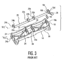
- Flanges 18b, 20b, 22b, and 24b of an eccentric shaft 26 are rotatably positioned in apertures 18a, 20a, 22a and 24a of housing 14, respectively.
- Eccentric shaft 26 is optionally a thin elongate blade having a rectangular cross-section, as shown in FIG. 3 .
- Inside each of flanges 18b, 20b, 22b, 24b are off-center apertures 18c, 20c, 22c, and 24c defining axis "A1.” In assembly axes A1 and A2 are radially misaligned.
- a threaded shaft 30 is rotatably positioned in apertures 18c and 20c for adjustably controlling the interpupillary distance (IPD) of a single monocular.
- a threaded shaft 32 is rotatably positioned in apertures 22c and 24c for adjustably controlling the interpupillary distance (IPD) of the adjacent monocular.
- a single monocular (not shown) is mounted onto threaded shaft 30.
- the monocular includes a threaded aperture 13 (see FIG. 4B ) for receiving threaded shaft 30.
- One end of threaded shaft 30 extends through wall 18 of housing 14. Consequently, the free end of threaded shaft 30 extends from the space in section 36 at the underside of housing 14 to the outside of wall 18.
- the opposing end of threaded shaft 30 extends through aperture 20c in flange 20b, which is disposed in aperture 20a of wall 20. Consequently, this end of threaded shaft 30 extends from space 36 at the underside of housing 14 into the space in section 38.
- a second monocular (not shown) is mounted onto threaded shaft 32.
- the monocular includes a threaded aperture for receiving threaded shaft 32.
- the threaded shaft 32 is rotatably received in apertures 22c and 24c of walls 22 and 24, respectively.
- One end of threaded shaft 32 extends through aperture 24c in flange 24b, such that the free end of threaded shaft 32 extends through wall 24 and outside of housing 14.
- the opposing end of threaded shaft 32 extends through aperture 22c in flange 22b, such that the end of shaft 32 extends into section 38.
- threaded shaft 32 As shown in FIG. 2b , the end of threaded shaft 32 that extends into space 38 is threaded and carries a washer member 40 which is secured axially on threaded shaft 32 by a threaded nut 42. Consequently, threaded shaft 32 is prevented from translating out of aperture 22c in flange 22b upon rotation of threaded shaft 32.
- threaded shaft 30 that extends into space 38 is threaded and carries a washer member (not shown) which is secured axially on the threaded shaft 30 by a threaded nut (not shown). Consequently, threaded shaft 30 is prevented from translating out of aperture 20c upon rotation of threaded shaft 30.
- Control knobs 40 and 42 are coupled to the free ends of shafts 32 and 30, respectively, for rotating shafts 32 and 30 about axis A1 and translating the monoculars parallel to axis A1.
- the free end of threaded shaft 32 that extends through wall 24 and outside of housing 14 is coupled to or extends from control knob 40.
- the free end of threaded shaft 30 that extends through wall 18 and outside of housing 14 is coupled to or extends from control knob 42.
- control knobs 42 and 40 are rotated, they respectively cause shafts 30 and 32 to rotate about axis A1 thereby translating the monoculars toward and away from each other along an axis parallel to axis A1 to adjust for varying eye separations. Because each of the monoculars 12 is respectively coupled to an independent shaft 30 or 32, the shafts 30 and 32 may be rotated independently of each other to translate a single monocular to adjust the IPD.
- prior art night vision device 10 also includes provisions for tilting the monoculars. More particularly, rotation of eccentric shaft 26 causes rotation (i.e., tilt) of the monoculars about axis A2.
- a lever 28 extending from flange 18b of shaft 26 is provided for rotating eccentric shaft 26.
- the pivot lever 28 of the eccentric shaft 26 extends outwardly beyond one end of housing 14, as shown in FIGS. 2a and 2b .
- shafts 30 and 32 are configured to rotate independent of eccentric shaft 26
- rotation of eccentric shaft 26 causes movement of shafts 30 and 32 about axis "A2,” thereby simultaneously tilting both monoculars 12 about axis A2.
- Axis A2 is oriented parallel and offset with respect to axis A1, the importance of which is described hereinafter.
- Each of the flanges 18b, 20b, 22b, and 24b are connected together by eccentric shaft 26.
- flanges 18b, 20b, 22b, and 24b are positioned within respective apertures 18a, 20a, 22a and 24a defined within housing 14.
- the apertures 18a, 20a, 22a and 24a together define axis "A2.”
- Each of flanges 18b, 20b, 22b, and 24b has an off-center aperture 18c, 20c, 22c, and 24c defined along axis A1.
- axis A2 is oriented parallel and offset with respect to axis A1.
- Off-center apertures 18c and 20c receive threaded shaft 30 and off-center apertures 22c and 24c receive threaded shaft 32. Both shafts 30 and 32 are coupled to respective monoculars 12. Rotation of eccentric shaft 26 about axis A2 causes rotation of shafts 30 and 32 about axis A2, by virtue of the radial misalignment (i.e., eccentricity) between axes A1 and A2. Rotation of shafts 30 and 32 about axis A2 tilts the monoculars 12 about axis A2.
- eccentric shaft 26 rotates flanges 18b, 20b, 22b, and 24b, shaft 30 and shaft 32 relative to housing 14 about axis A2. Because each of monoculars are coupled to shafts 30 and 32 and axes A1 and A2 are misaligned, rotation of lever 28 tilts each of the monoculars relative to housing 14 and relative to a user's eyes.
- eccentric shaft 26 and its associated flanges 18b, 20b, 22b, and 24b provides a means of tilting the line-of-sight of the two monoculars simultaneously.
- the lever 28 may be used to adjust the tilt of the monoculars to align with the user's line-of-sight.
- the prior art eccentric shaft 26 uses an o-ring 46 to provide rotational friction between the eccentric shaft 26 and the housing 14.
- the o-ring 46 is placed in a groove 18d of flange 18b, near adjustment lever 28.
- the purpose of the o-ring is to provide frictional resistance against the housing.
- the rotational friction force occurs between o-ring 46 and aperture 18a of wall 18 when flange 18b is inserted into aperture 18a.
- the o-ring acts as a frictional resistor between the eccentric shaft 26 and the housing 14.
- the frictional interface between o-ring 46 and aperture 18a is controlled by tight tolerances between flange 18b of eccentric shaft 26, housing 14, and o-ring 46.
- rotational friction provided by o-ring 46 is to minimize or prevent the night vision binocular from inadvertently tilting due to vibration. Another purpose is to provide a smooth resistance during adjustment of the rotational position of monoculars 12.
- the prior art device does not include a positive locking mechanism for preventing rotation of eccentric shaft 26.
- eccentric shaft 26 there remains the possibility for eccentric shaft 26 to overcome the frictional resistance provided by o-ring 46. Consequently, monoculars 12 could inadvertently tilt upon being subjected to vibration or violent external movements. It is therefore necessary to provide a design that prevents, or at least better inhibits, eccentric shaft 26 from inadvertently rotating during operation of night vision device 10.
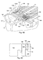
- FIGS. 4a-4c depict a mechanism for tilting and locking the monoculars 12 according to a first exemplary embodiment of the invention.
- FIG. 4a depicts a front perspective view of the tilt mechanism.
- FIG. 4b depicts a cross-sectional view of the tilt mechanism of FIG. 4a taken along the lines 4b-4b.
- FIG. 4c depicts a cross-sectional view of the locking apparatus of FIG. 4b taken along the lines 4c-4c.
- the tilt mechanism of FIGS. 4a-4c is similar to the tilt mechanism of FIGS. 2a-3 , however, the tilt mechanism of FIGS. 4a-4c includes provisions for locking the monoculars 12 in place.
- the tilt mechanism generally includes an eccentric shaft 126, similar to eccentric shaft 26 of FIG. 3 .
- Rotation of eccentric shaft 126 adjusts the tilt of both monoculars 12 (one shown).
- a threaded shaft 130 integrally formed with control knob 142 is rotatably positioned through an aperture 118c provided in flange 118b of eccentric shaft 126.
- rotation of threaded shaft 130 about axis A1 does not induce rotation of eccentric shaft 126, however, rotation of eccentric shaft 126 about axis A2 induces rotation of threaded stud 130 about axis A2, by virtue of the radial misalignment (i.e., eccentricity) between off-center aperture 118c (defined along axis A1) of flange 118b and aperture 118a (defined along axis A2) of housing wall 118.
- lever 128 is independent of flange 118b of eccentric shaft 126 and mounted to wall 118 of housing 114 by a fastener 150. While only flange 118b of eccentric shaft 126 is shown in FIGS. 4a and 4b , the remaining portion of eccentric shaft 126 is similar to that of eccentric shaft 26 shown in FIG. 3 .
- the lever 128 and flange 118b each include a set of gears 162 and 160, respectively, for operative engagement. Rotation of gears 162 of lever 128 induces rotation of gears 160 of flange 118b consequently rotating eccentric shaft 126 and tilting the monoculars 12.
- the eccentric shaft 126 uses an o-ring 146 to provide rotational friction between eccentric shaft 126 and housing 114.
- the o-ring 146 is placed in a groove 118d of flange 118b.
- the o-ring 146 provides frictional resistance against housing 114.
- the rotational friction force occurs between o-ring 146 and aperture 118a of wall 118 when flange 118b is inserted into aperture 118a.
- o-ring 146 acts as a frictional resistor between eccentric shaft 126 and housing 114. Because friction between eccentric shaft 126 and housing 114 alone may not be sufficient to prevent inadvertent rotation of eccentric shaft 126, the tilt mechanism of FIGS. 4a and 4b include additional provisions for locking eccentric shaft 126 in place.
- lever 128 includes another set of gear teeth 166 for selectively engaging a set of gear teeth 168 defined on a stop 164. Interengagement between gear teeth 166 and 168 prevents inadvertent rotation of lever 128.
- eccentric shaft 126 is also prevented from rotation by virtue of the engagement between gears 160 and 162 of the flange 118b and lever 128, respectively.
- the monoculars 12 are prevented from tilting.
- gear teeth 166 of lever 128 are disposed on the rear surface of lever 128, whereas gear teeth 162 of lever 128 are disposed on a side surface of lever 128. It should be understood that gear teeth 162 and 166 are entirely separate and perform separate functions.
- stop 164 is fixedly mounted in a slot 167 formed in wall 118 of housing 114, and prevented from movement.
- stop 164 may not be a separate component as shown.
- gear teeth 168 may extend from wall 118 of housing 114 to achieve the same result.
- engagement between lever 126 and stop 164 is not limited to gears. Those skilled in the art will recognize that other ways of preventing respective rotation or translation between lever 126 and stop 164 exist.
- the lever 128 is moveable between a deployed position (not shown) and a retracted position (shown in FIGS. 4b and 4c ).
- gear teeth 166 of lever 126 are separated from gear teeth 168 of stop 164 to permit rotation of lever 128 (causing rotation of shaft 126 and tilting of optical device 12).
- gear teeth 166 of lever 126 are engaged with gear teeth 168 of stop 164 to prevent rotation of lever 128 (preventing rotation of shaft 126 and tilting of optical device 12).
- a spring 152 biases lever 128 to the retracted position shown in FIGS. 4b and 4c .
- the spring 152 is positioned in a recess 153 formed in lever 128 between the head of fastener 150 and a surface of lever 128. In the retracted position, spring 152 urges gear teeth 166 of lever 128 against gear teeth 168 of stop 164, thereby preventing rotation of lever 128.
- a user translates lever 128 away from housing 114 against the force of spring 152 to relocate lever 128 to a deployed position.
- Translating lever 128 away from housing 114 compresses spring 152 and separates gear teeth 166 of lever 126 from gear teeth 168 of stop 164.
- gear teeth 166 and 168 the user is free to rotate lever 126 in either a clockwise or a counter clockwise direction thereby rotating flange 118b of eccentric shaft 126 and tilting binoculars 12.
- the lever 26 returns to the stowed position once it is released, by virtue of the force of spring 152.
- stop 164 is fixed in place and lever 128 is moveable between a deployed position a retracted position
- lever 128 may be fixed in place and stop 164 may be moveable between a deployed position and retracted position.
- FIG. 5 depicts a front perspective view and a rear perspective view, respectively, of a mechanism for selectively locking the rotational position of the binocular night vision goggle of FIG. 1 , according to a second exemplary embodiment of the invention. Similar to the binocular tilt mechanism of FIGS. 4a-4c , the tilt mechanism of FIG. 5 includes provisions for locking the binoculars in place.
- the tilt mechanism includes a lever 228 for rotating an eccentric shaft (not shown) to tilt the binoculars 12 with respect to the eye of the user.
- the lever 228 is integral with the eccentric shaft.
- a handle 229 is provided on lever 228 for rotating the lever 228.
- lever 228 of FIG. 5 extends from a flange of the eccentric shaft, and a control knob 242 is positioned through an aperture (not shown) provided in lever 228 for rotating a threaded shaft (not shown) within housing 214 to control the PID of the binoculars.
- the lever 226 includes a series of apertures 270 (four shown) for selective engagement with resilient element 272 positioned on housing 214.
- resilient element 272 positively engages (i.e., "snaps" into) a single aperture 270, thereby preventing further rotation of lever 226. It should be understood that rotation of lever 226 rotates the eccentric shaft positioned within housing 214 thereby tilting binoculars 12, as described with reference to the previous embodiments.
- the apertures 270 may be circular thru-holes, as shown, or circular depressions formed on the rear surface of lever 226.
- the apertures 270 are sized to receive resilient element 272.
- the resilient element 272 is optionally a ball plunger positioned on side 218 of housing 214. Suitable ball plungers are sold and distributed by Monroe PMP, Incorporated of Auburn Hills, Michigan, USA. Those skilled in the art will recognize that resilient element 272 may be a bearing or a spring loaded bearing at least partially extending beyond wall 218 of housing 214 for engaging an aperture 270 of lever 228. Additionally, resilient element 272 is not limited to being spring loaded.
- engagement between resilient element 272 and aperture 270 captivates lever 228 in a fixed position.
- a user can disengage resilient element 272 and aperture 270 by rotating lever 228 with sufficient force, so as to depress resilient element 272.
- resilient element 272 Once resilient element 272 is depressed the user may rotate lever 228 until resilient element 272 engages an adjacent aperture 270.
- the engagement force between resilient element 272 and aperture 270 is desirably high enough to resist inadvertent disengagement due to vibration, yet low enough to permit manual disengagement by a user rotating lever 228.
- lever 228 includes apertures 270 and housing 214 includes resilient element 272 in this exemplary embodiment, those skilled in the art will recognize that apertures 270 may be defined along housing 214 and resilient element 272 may be provided on lever 228 without departing from the scope of the invention.
- FIG. 6a depicts a front perspective view of a mechanism for locking the rotational position of the binocular night vision goggle of FIG. 1 , according to a third exemplary embodiment of the invention.
- FIG. 6b depicts a cross-sectional view of a magneto-rheological bearing of FIG. 6a taken along the lines 6B-6B. Similar to the binocular tilt mechanisms of FIGS. 4a-4c and 5 the tilt mechanism of FIGS. 6a and 6b includes provisions for selectively locking the rotational position of monoculars 12.
- the tilt mechanism generally includes a lever 328 for rotating an eccentric shaft (not shown) to tilt the binoculars 12 with respect to the eye of the user.
- a magneto-rheological (MR) bearing 380 is interoperably positioned between lever 328 and the eccentric shaft, such that rotation of lever 328 is transmitted through MR bearing 380 to induce rotation of the eccentric shaft.
- the MR bearing 380 includes an exterior casing 387 that is fixedly mounted to housing 314, thereby preventing rotation of exterior casing 387.
- a bearing shaft 389 is rotatably positioned about axis 390 within exterior casing 387 of bearing 380.
- MR bearing 380 is filled with a magneto-rheological (MR) fluid 385.
- MR magneto-rheological
- the viscosity of MR fluid 385 increases, to the point of becoming a viscoelastic solid.
- MR fluid 385 prevents rotation of shaft 389, thereby preventing rotation of lever 328, the eccentric shaft, and monoculars 12.
- a magnet 382 is slideably positioned within a slot 381 formed on the top side of housing 314.
- the magnet 382 is slideably coupled to housing 314 for translating between a first position proximal to MR bearing 380, as shown in FIG. 6a , and a second position distal to MR bearing 380.
- MR fluid 385 is subjected to a strong magnetic field and solidifies to limit rotation of shaft 389 of magnet 382, lever 328, the eccentric shaft, and binoculars 12.
- MR fluid 385 is not subjected to a strong magnetic field and remains in a liquid state thereby permitting rotation of shaft 389, lever 328, the eccentric shaft, and monoculars 12.
- the position of magnet 382 may be adjusted manually by the user.
Landscapes
- Physics & Mathematics (AREA)
- General Physics & Mathematics (AREA)
- Optics & Photonics (AREA)
- Astronomy & Astrophysics (AREA)
- Telescopes (AREA)
- Instrument Panels (AREA)
- Lighting Device Outwards From Vehicle And Optical Signal (AREA)
Abstract
Description
- The present invention relates to a locking mechanism for selectively fixing the rotational position of a field helmet mounted optical device, such as night vision binoculars.
- A binocular night vision device uses a pair of monocular night vision scopes which are mounted and associated with one another in such a way as to provide the user of the device with binocular vision, thereby allowing the user to have a night-time view with depth perception. Users typically operate the night vision device in a variety of positions, such as standing erect, lying flat on the ground, sitting in a cockpit of an airplane, hiding behind protective cover, and so forth. Given the wide variety of positions a user may operate a night vision device, many night vision devices include provisions for adjustably tilting (i.e., rotating) the night vision device with respect to the eye of the user to adapt the night vision device to the body orientation of the user. Furthermore, field helmet mounted optical devices may include provisions for locking the rotational position of the night vision device once the night vision device is rotated to a desired position.
- In practice, night vision devices are often subject to violent external movements or environmental changes, such as temperature adjustments. For example, helmet mounted night vision devices used for aviation experience high and low frequency vibration, mechanical shock and multi-axis elevated G loads. Under those conditions, many conventional devices for retaining the night vision device in a fixed position are often inadequate for preventing the night vision device from drifting from its original setting with respect to the field helmet, thereby requiring constant readjustment of the night vision device.
- In view of the foregoing, there is a continuing need to further develop and refine devices for selectively locking a helmet mounted night vision device in a fixed position, in the interests of performance, safety and convenience.
- According to an aspect of the invention, a mechanism for permitting selective adjustment of the angular position of a head-mounted night vision device is provided. The mechanism comprises a housing positioned adjacent the night vision device. A shaft defining a longitudinal axis is at least partially positioned within or adjacent the housing. The shaft is rotatively coupled to the night vision device, wherein rotation of the shaft induces rotation of the night vision device. A moveable lever is coupled to the shaft for rotating the shaft. Means for selectively limiting rotation of the shaft are provided, wherein the means are moveable between a first position and a second position. In the first position the means permit rotation of the shaft and the optical device, and in the second position the means limit rotation of the shaft and the optical device.
- According to another aspect of the invention, another mechanism for permitting selective adjustment of the angular position of a head-mounted optical device is provided. The mechanism comprises a stop positioned on the housing for selective engagement with a set of gear teeth provided on the moveable lever. Either the moveable lever or the stop are positionable between a deployed position and a retracted position. In the deployed position the set of gear teeth are separated from the stop to permit movement of the moveable lever, rotation of the shaft and rotation of the optical device. In the retracted position the set of gear teeth are engaged with the stop to limit movement of the moveable lever, rotation of the shaft and rotation of the optical device.
- According to yet another aspect of the invention, the moveable lever includes either a resilient element or an aperture for receiving a resilient element. Either another resilient element or another aperture are positioned on the housing for selectively receiving the aperture or the resilient element of the moveable lever. The resilient element of the housing or the moveable lever is deformable for releasable engagement with the aperture of the moveable lever or the housing, respectively.
- According to still another aspect of the invention, a magneto-rheological bearing is coupled to the shaft and the housing for selectively permitting rotation of the shaft. A magnet is slideably coupled to the housing for translating between a first position proximal to the bearing and a second position distal to the bearing, wherein in the proximal position the bearing limits rotation of the shaft, and in the distal position the bearing permits rotation of the shaft.
- The invention is best understood from the following detailed description when read in connection with the accompanying drawing. It is emphasized that, according to common practice, the various features of the drawing are not to scale. Included in the drawing are the following figures:
- FIG. 1
- is a perspective view of a prior art binocular night vision goggle.
- FIG. 2a
- is a top perspective view of a prior art housing for supporting the binocular night vision goggle of
FIG. 1 . - FIG. 2b
- is a bottom perspective view of the prior art housing of
FIG 2a . - FIG. 3
- is an exploded perspective view of the prior art housing, eccentric shaft, and o-ring of the prior art binocular night vision goggle of
FIG. 1 . - FIG. 4a
- depicts a front perspective view of a mechanism for locking the rotational position of the binocular night vision goggle of
FIG. 1 according to a first exemplary embodiment of the invention, wherein the mechanism includes a spring loaded lever having gears for selectively rotating the eccentric shaft. - FIG. 4b
- depicts a cross-sectional view of the mechanism of
FIG. 4a taken along the lines 4b-4b. - FIG. 4c
- depicts a cross-sectional view of the mechanism of
FIG. 4b taken along the lines 4c-4c. - FIG. 5
- depicts a front perspective view of another mechanism for locking the rotational position of the binocular night vision goggle of
FIG. 1 , according to a second exemplary embodiment of the invention, wherein the mechanism includes a lever having apertures for selectively receiving a spring element positioned on the housing. - FIG. 6a
- depicts a front perspective view of yet another mechanism for locking the rotational position of the binocular night vision goggle of
FIG. 1 , accord- ing to a third exemplary embodiment of the invention, wherein a magnet is slideably coupled to the housing for selectively actuating a magnetorheological bearing mounted between the shaft and the housing. - FIG. 6b
- depicts a cross-sectional view of the magneto-rheological bearing of
FIG. 6a taken along thelines 6B-6B. - This invention will now be described with reference to several embodiments selected for illustration in the drawings. It will be appreciated that the scope and spirit of the invention are not limited to the illustrated embodiments.
- Referring generally to the figures and according to an aspect of the invention, a mechanism for permitting selective adjustment of the angular position of a head-mounted
night vision device 12 is provided. The mechanism comprises ahousing night vision device 12. Ashaft 126 defining a longitudinal axis A2 is at least partially positioned within or adjacent thehousing shaft 126 is rotatively coupled to thenight vision device 12, wherein rotation of theshaft 126 induces rotation of thenight vision device 12. Amoveable lever shaft 126 for rotating theshaft 126.Means shaft 126 are provided, wherein themeans - According to another aspect of the invention, another mechanism for permitting selective adjustment of the angular position of a head-mounted
optical device 12 is provided. The mechanism comprises astop 164 positioned on thehousing 114 for selective engagement with a set ofgear teeth 166 provided on themoveable lever 128. Either themoveable lever 128 or thestop 164 are positionable between a deployed position and a retracted position. In the deployed position the set ofgear teeth 166 are separated from thestop 164 to permit movement of themoveable lever 128, rotation of theshaft 126 and rotation of theoptical device 12. In the retracted position the set ofgear teeth 166 are engaged with thestop 164 to limit movement of themoveable lever 128, rotation of theshaft 126 and rotation of theoptical device 12. - According to yet another aspect of the invention, the
moveable lever 228 includes either a resilient element 272 or anaperture 270 for receiving a resilient element 272. Either another resilient element 272 or anotheraperture 270 are positioned on thehousing 214 for selectively receiving theaperture 270 or the resilient element 272 of themoveable lever 228. The resilient element 272 of thehousing 214 or themoveable lever 228 is deformable for releasable engagement with theaperture 270 of themoveable lever 228 or thehousing 214, respectively. - According to still another aspect of the invention, a magneto-
rheological bearing 380 is coupled to theshaft 126 and thehousing 314 for selectively permitting rotation of theshaft 126. Amagnet 382 is slideably coupled to thehousing 314 for translating between a first position proximal to thebearing 380 and a second position distal to thebearing 380, wherein in the proximal position the bearing 380 limits rotation of theshaft 126, and in the distal position the bearing 380 permits rotation of theshaft 126. -
FIGS. 1-3 illustrate a prior artnight vision device 10. The prior artnight vision device 10 is also described inU.S. Patent No. 6,924,931 to Lam et al ., the contents of which are incorporated herein by reference in their entirety. As depicted inFIG. 1 , prior artnight vision device 10 includes a pair ofnight vision monoculars 12 which can be suspended in front of a user's eyes. The prior artnight vision device 10 includes provisions for (1) tilting the monoculars, and (2) translating each monocular to adjust the horizontal spacing between themonoculars 12 to match the interpupillary distance (IPD) of a user. The interpupillary distance (IPD) is defined as the distance between the user's pupils. - More particularly, the
night vision device 10 includes an IPD adjustment mechanism to permit adjustment of the horizontal spacing between themonoculars 12 to match the interpupillary distance (IPD) of a user. The IPD adjustment mechanism translates the monoculars toward each other and away from each other. The IPD adjustment mechanism is positioned in ahousing 14 of prior artnight vision device 10, as described hereinafter. -
FIGS. 2a and 2b depict a top view and a bottom view ofhousing 14, respectively, omitting the binocular and the field helmet mounting component. Thehousing 14 is indirectly mounted to a field helmet (not shown). Thehousing 14 has a laterally elongated rectangular shape in plan view, and is also of a generally rectangular shape in both frontal and side elevation views. - As shown in
FIGS. 2b and3 , the lower portion ofhousing 14 is divided into threesections walls walls aperture 18a is disposed inwall 18,aperture 20a is disposed inwall 20,aperture 22a is disposed inwall 22, and aperture 24a is disposed inwall 24.Apertures -
Flanges eccentric shaft 26 are rotatably positioned inapertures housing 14, respectively.Eccentric shaft 26 is optionally a thin elongate blade having a rectangular cross-section, as shown inFIG. 3 . Inside each offlanges center apertures - A threaded
shaft 30 is rotatably positioned inapertures shaft 32 is rotatably positioned inapertures - Referring still to
FIGS. 2b and3 , a single monocular (not shown) is mounted onto threadedshaft 30. The monocular includes a threaded aperture 13 (seeFIG. 4B ) for receiving threadedshaft 30. One end of threadedshaft 30 extends throughwall 18 ofhousing 14. Consequently, the free end of threadedshaft 30 extends from the space insection 36 at the underside ofhousing 14 to the outside ofwall 18. The opposing end of threadedshaft 30 extends throughaperture 20c inflange 20b, which is disposed inaperture 20a ofwall 20. Consequently, this end of threadedshaft 30 extends fromspace 36 at the underside ofhousing 14 into the space insection 38. - A second monocular (not shown) is mounted onto threaded
shaft 32. The monocular includes a threaded aperture for receiving threadedshaft 32. The threadedshaft 32 is rotatably received inapertures walls shaft 32 extends throughaperture 24c inflange 24b, such that the free end of threadedshaft 32 extends throughwall 24 and outside ofhousing 14. The opposing end of threadedshaft 32 extends throughaperture 22c inflange 22b, such that the end ofshaft 32 extends intosection 38. - As shown in
FIG. 2b , the end of threadedshaft 32 that extends intospace 38 is threaded and carries awasher member 40 which is secured axially on threadedshaft 32 by a threadednut 42. Consequently, threadedshaft 32 is prevented from translating out ofaperture 22c inflange 22b upon rotation of threadedshaft 32. Similarly, the end of threadedshaft 30 that extends intospace 38 is threaded and carries a washer member (not shown) which is secured axially on the threadedshaft 30 by a threaded nut (not shown). Consequently, threadedshaft 30 is prevented from translating out ofaperture 20c upon rotation of threadedshaft 30. - Control knobs 40 and 42 are coupled to the free ends of
shafts shafts shaft 32 that extends throughwall 24 and outside ofhousing 14 is coupled to or extends fromcontrol knob 40. Similarly, the free end of threadedshaft 30 that extends throughwall 18 and outside ofhousing 14 is coupled to or extends fromcontrol knob 42. In operation, when control knobs 42 and 40 are rotated, they respectively causeshafts monoculars 12 is respectively coupled to anindependent shaft shafts - As noted previously, prior art
night vision device 10 also includes provisions for tilting the monoculars. More particularly, rotation ofeccentric shaft 26 causes rotation (i.e., tilt) of the monoculars about axis A2. Alever 28 extending fromflange 18b ofshaft 26 is provided for rotatingeccentric shaft 26. Thepivot lever 28 of theeccentric shaft 26 extends outwardly beyond one end ofhousing 14, as shown inFIGS. 2a and 2b . Whileshafts eccentric shaft 26, rotation ofeccentric shaft 26 causes movement ofshafts monoculars 12 about axis A2. Axis A2 is oriented parallel and offset with respect to axis A1, the importance of which is described hereinafter. - Each of the
flanges eccentric shaft 26. In assembled form,flanges respective apertures housing 14. Theapertures flanges center aperture - Off-
center apertures shaft 30 and off-center apertures shaft 32. Bothshafts respective monoculars 12. Rotation ofeccentric shaft 26 about axis A2 causes rotation ofshafts shafts monoculars 12 about axis A2. - In other words, rotation of
lever 28 ofeccentric shaft 26 about axis A2 rotatesflanges shaft 30 andshaft 32 relative tohousing 14 about axis A2. Because each of monoculars are coupled toshafts lever 28 tilts each of the monoculars relative tohousing 14 and relative to a user's eyes. Thus,eccentric shaft 26 and its associatedflanges lever 28 may be used to adjust the tilt of the monoculars to align with the user's line-of-sight. - As shown in
FIG. 3 , the prior arteccentric shaft 26 uses an o-ring 46 to provide rotational friction between theeccentric shaft 26 and thehousing 14. The o-ring 46 is placed in agroove 18d offlange 18b, nearadjustment lever 28. After theeccentric shaft 26 is assembled to the housing assembly, the purpose of the o-ring is to provide frictional resistance against the housing. The rotational friction force occurs between o-ring 46 andaperture 18a ofwall 18 whenflange 18b is inserted intoaperture 18a. Thus, the o-ring acts as a frictional resistor between theeccentric shaft 26 and thehousing 14. The frictional interface between o-ring 46 andaperture 18a is controlled by tight tolerances betweenflange 18b ofeccentric shaft 26,housing 14, and o-ring 46. One of the purposes of the rotational friction provided by o-ring 46 is to minimize or prevent the night vision binocular from inadvertently tilting due to vibration. Another purpose is to provide a smooth resistance during adjustment of the rotational position ofmonoculars 12. The prior art device does not include a positive locking mechanism for preventing rotation ofeccentric shaft 26. - Accordingly, there remains the possibility for
eccentric shaft 26 to overcome the frictional resistance provided by o-ring 46. Consequently,monoculars 12 could inadvertently tilt upon being subjected to vibration or violent external movements. It is therefore necessary to provide a design that prevents, or at least better inhibits,eccentric shaft 26 from inadvertently rotating during operation ofnight vision device 10. -
FIGS. 4a-4c depict a mechanism for tilting and locking themonoculars 12 according to a first exemplary embodiment of the invention.FIG. 4a depicts a front perspective view of the tilt mechanism.FIG. 4b depicts a cross-sectional view of the tilt mechanism ofFIG. 4a taken along the lines 4b-4b.FIG. 4c depicts a cross-sectional view of the locking apparatus ofFIG. 4b taken along the lines 4c-4c. The tilt mechanism ofFIGS. 4a-4c is similar to the tilt mechanism ofFIGS. 2a-3 , however, the tilt mechanism ofFIGS. 4a-4c includes provisions for locking themonoculars 12 in place. - As shown in
FIGS. 4a and4b , the tilt mechanism generally includes aneccentric shaft 126, similar toeccentric shaft 26 ofFIG. 3 . Rotation ofeccentric shaft 126 adjusts the tilt of both monoculars 12 (one shown). A threadedshaft 130 integrally formed withcontrol knob 142 is rotatably positioned through anaperture 118c provided inflange 118b ofeccentric shaft 126. Similar to the prior art device, rotation of threadedshaft 130 about axis A1 does not induce rotation ofeccentric shaft 126, however, rotation ofeccentric shaft 126 about axis A2 induces rotation of threadedstud 130 about axis A2, by virtue of the radial misalignment (i.e., eccentricity) between off-center aperture 118c (defined along axis A1) offlange 118b andaperture 118a (defined along axis A2) ofhousing wall 118. - Unlike
eccentric shaft 26 ofFIG. 3 ,lever 128 is independent offlange 118b ofeccentric shaft 126 and mounted to wall 118 ofhousing 114 by afastener 150. While onlyflange 118b ofeccentric shaft 126 is shown inFIGS. 4a and4b , the remaining portion ofeccentric shaft 126 is similar to that ofeccentric shaft 26 shown inFIG. 3 . Thelever 128 andflange 118b each include a set ofgears gears 162 oflever 128 induces rotation ofgears 160 offlange 118b consequently rotatingeccentric shaft 126 and tilting themonoculars 12. - As shown in
FIGS. 4a and4b , theeccentric shaft 126 uses an o-ring 146 to provide rotational friction betweeneccentric shaft 126 andhousing 114. The o-ring 146 is placed in agroove 118d offlange 118b. The o-ring 146 provides frictional resistance againsthousing 114. The rotational friction force occurs between o-ring 146 andaperture 118a ofwall 118 whenflange 118b is inserted intoaperture 118a. Thus, o-ring 146 acts as a frictional resistor betweeneccentric shaft 126 andhousing 114. Because friction betweeneccentric shaft 126 andhousing 114 alone may not be sufficient to prevent inadvertent rotation ofeccentric shaft 126, the tilt mechanism ofFIGS. 4a and4b include additional provisions for lockingeccentric shaft 126 in place. - As best shown in
FIG. 4c ,lever 128 includes another set ofgear teeth 166 for selectively engaging a set ofgear teeth 168 defined on astop 164. Interengagement betweengear teeth lever 128. By preventing rotation oflever 128,eccentric shaft 126 is also prevented from rotation by virtue of the engagement betweengears flange 118b andlever 128, respectively. Moreover, by preventing rotation ofeccentric shaft 126, themonoculars 12 are prevented from tilting. - The
gear teeth 166 oflever 128 are disposed on the rear surface oflever 128, whereasgear teeth 162 oflever 128 are disposed on a side surface oflever 128. It should be understood thatgear teeth - According to one aspect of the invention, stop 164 is fixedly mounted in a slot 167 formed in
wall 118 ofhousing 114, and prevented from movement. Those skilled in the art will recognize that stop 164 may not be a separate component as shown. Forexample gear teeth 168 may extend fromwall 118 ofhousing 114 to achieve the same result. Additionally, engagement betweenlever 126 and stop 164 is not limited to gears. Those skilled in the art will recognize that other ways of preventing respective rotation or translation betweenlever 126 and stop 164 exist. - The
lever 128 is moveable between a deployed position (not shown) and a retracted position (shown inFIGS. 4b and 4c ). In a deployed position, gearteeth 166 oflever 126 are separated fromgear teeth 168 ofstop 164 to permit rotation of lever 128 (causing rotation ofshaft 126 and tilting of optical device 12). In a retracted position, as shown inFIGS. 4b and 4c ,gear teeth 166 oflever 126 are engaged withgear teeth 168 ofstop 164 to prevent rotation of lever 128 (preventing rotation ofshaft 126 and tilting of optical device 12). - A
spring 152 biases lever 128 to the retracted position shown inFIGS. 4b and 4c . Thespring 152 is positioned in arecess 153 formed inlever 128 between the head offastener 150 and a surface oflever 128. In the retracted position,spring 152 urges gearteeth 166 oflever 128 againstgear teeth 168 ofstop 164, thereby preventing rotation oflever 128. - According to one exemplary use of the invention, a user translates
lever 128 away fromhousing 114 against the force ofspring 152 to relocatelever 128 to a deployed position. Translatinglever 128 away fromhousing 114 compressesspring 152 and separates gearteeth 166 oflever 126 fromgear teeth 168 ofstop 164. Upon separation ofgear teeth lever 126 in either a clockwise or a counter clockwise direction thereby rotatingflange 118b ofeccentric shaft 126 and tiltingbinoculars 12. Thelever 26 returns to the stowed position once it is released, by virtue of the force ofspring 152. - While in this
exemplary embodiment stop 164 is fixed in place andlever 128 is moveable between a deployed position a retracted position, those skilled in the art will recognize thatlever 128 may be fixed in place and stop 164 may be moveable between a deployed position and retracted position. -
FIG. 5 depicts a front perspective view and a rear perspective view, respectively, of a mechanism for selectively locking the rotational position of the binocular night vision goggle ofFIG. 1 , according to a second exemplary embodiment of the invention. Similar to the binocular tilt mechanism ofFIGS. 4a-4c , the tilt mechanism ofFIG. 5 includes provisions for locking the binoculars in place. - The tilt mechanism includes a
lever 228 for rotating an eccentric shaft (not shown) to tilt thebinoculars 12 with respect to the eye of the user. In this emdodiment thelever 228 is integral with the eccentric shaft. A handle 229 is provided onlever 228 for rotating thelever 228. Similar to the binocular tilt mechanism ofFIGS. 2a-3 , and unlike the binocular tilt mechanism ofFIGS. 4a-4c ,lever 228 ofFIG. 5 extends from a flange of the eccentric shaft, and acontrol knob 242 is positioned through an aperture (not shown) provided inlever 228 for rotating a threaded shaft (not shown) withinhousing 214 to control the PID of the binoculars. - The lever 226 includes a series of apertures 270 (four shown) for selective engagement with resilient element 272 positioned on
housing 214. Upon rotation of lever 226, resilient element 272 positively engages (i.e., "snaps" into) asingle aperture 270, thereby preventing further rotation of lever 226. It should be understood that rotation of lever 226 rotates the eccentric shaft positioned withinhousing 214 thereby tiltingbinoculars 12, as described with reference to the previous embodiments. - The
apertures 270 may be circular thru-holes, as shown, or circular depressions formed on the rear surface of lever 226. Theapertures 270 are sized to receive resilient element 272. The resilient element 272 is optionally a ball plunger positioned onside 218 ofhousing 214. Suitable ball plungers are sold and distributed by Monroe PMP, Incorporated of Auburn Hills, Michigan, USA. Those skilled in the art will recognize that resilient element 272 may be a bearing or a spring loaded bearing at least partially extending beyondwall 218 ofhousing 214 for engaging anaperture 270 oflever 228. Additionally, resilient element 272 is not limited to being spring loaded. - Engagement between resilient element 272 and
aperture 270 captivateslever 228 in a fixed position. A user can disengage resilient element 272 andaperture 270 by rotatinglever 228 with sufficient force, so as to depress resilient element 272. Once resilient element 272 is depressed the user may rotatelever 228 until resilient element 272 engages anadjacent aperture 270. According to one aspect of the invention, the engagement force between resilient element 272 andaperture 270 is desirably high enough to resist inadvertent disengagement due to vibration, yet low enough to permit manual disengagement by auser rotating lever 228. - While
lever 228 includesapertures 270 andhousing 214 includes resilient element 272 in this exemplary embodiment, those skilled in the art will recognize thatapertures 270 may be defined alonghousing 214 and resilient element 272 may be provided onlever 228 without departing from the scope of the invention. -
FIG. 6a depicts a front perspective view of a mechanism for locking the rotational position of the binocular night vision goggle ofFIG. 1 , according to a third exemplary embodiment of the invention.FIG. 6b depicts a cross-sectional view of a magneto-rheological bearing ofFIG. 6a taken along thelines 6B-6B. Similar to the binocular tilt mechanisms ofFIGS. 4a-4c and 5 the tilt mechanism ofFIGS. 6a and6b includes provisions for selectively locking the rotational position ofmonoculars 12. - The tilt mechanism generally includes a
lever 328 for rotating an eccentric shaft (not shown) to tilt thebinoculars 12 with respect to the eye of the user. A magneto-rheological (MR) bearing 380 is interoperably positioned betweenlever 328 and the eccentric shaft, such that rotation oflever 328 is transmitted through MR bearing 380 to induce rotation of the eccentric shaft. The MR bearing 380 includes anexterior casing 387 that is fixedly mounted tohousing 314, thereby preventing rotation ofexterior casing 387. A bearingshaft 389 is rotatably positioned aboutaxis 390 withinexterior casing 387 ofbearing 380. The input end (not shown) of bearingshaft 389 is coupled to lever 328 and the output end (not shown) of bearingshaft 389 is coupled to the eccentric shaft (not shown) positioned withinhousing 314. As best shown inFIG. 6b , MR bearing 380 is filled with a magneto-rheological (MR)fluid 385. Upon being subject to a magnetic field, the viscosity of MR fluid 385 increases, to the point of becoming a viscoelastic solid. In a solid state,MR fluid 385 prevents rotation ofshaft 389, thereby preventing rotation oflever 328, the eccentric shaft, andmonoculars 12. - A
magnet 382 is slideably positioned within aslot 381 formed on the top side ofhousing 314. Themagnet 382 is slideably coupled tohousing 314 for translating between a first position proximal to MR bearing 380, as shown inFIG. 6a , and a second position distal to MR bearing 380. In the proximal position,MR fluid 385 is subjected to a strong magnetic field and solidifies to limit rotation ofshaft 389 ofmagnet 382,lever 328, the eccentric shaft, andbinoculars 12. In the distal position ofmagnet 382,MR fluid 385 is not subjected to a strong magnetic field and remains in a liquid state thereby permitting rotation ofshaft 389,lever 328, the eccentric shaft, andmonoculars 12. The position ofmagnet 382 may be adjusted manually by the user. - Although the invention is illustrated and described herein with reference to specific embodiments, the invention is not intended to be limited to the details shown. Rather, various modifications may be made in the details within the scope and range of equivalents of the claims and without departing from the spirit of the invention.
Claims (16)
- A mechanism for permitting selective adjustment of the angular position of a head-mounted night vision device (12), said mechanism comprising:a housing (114, 214, 314) positioned adjacent the night vision device;a shaft (126) defining a longitudinal axis (A2) being at least partially positioned within or adjacent the housing, said shaft being rotatively coupled to the night vision device, wherein rotation of the shaft induces rotation of the night vision device with respect to the housing; anda moveable lever (128, 228, 328) coupled to the shaft for rotating the shaft;means (160 and 162, 270 and 272, 380 and 382) for selectively limiting rotation of the shaft, said means being positioned on the moveable lever or the housing,wherein the means (160 and 162, 270 and 272, 380 and 382) are moveable between a first position and a second position, wherein in the first position the means permit rotation of the shaft and the optical device, and in the second position the means limit rotation of the shaft and the optical device.
- The mechanism of claim 1, said housing including a stop (164), and said means comprising a set of gear teeth (166) positioned on said moveable lever (128) for selective engagement with said stop, wherein in said first position said set of gear teeth (166) are separated from said stop, and in said second position said set of gear teeth are engaged with said stop.
- The mechanism of claim 1, said means being positioned on said moveable lever (228) and comprising either a resilient element (272) or an aperture (270) for receiving a resilient element; and
a resilient element or an aperture positioned on said housing for selectively receiving the aperture or the resilient element of the moveable lever, respectively, wherein said resilient element of said housing or said moveable lever is deformable for releasable engagement with said aperture of said moveable lever or said housing, respectively. - The mechanism of claim 1 further comprising a magneto-rheological bearing (380) coupled to said shaft (126) and said housing for selectively permitting rotation of said shaft; and
said means comprising a magnet (382) coupled to said housing (314) for translating between the second position proximal to said bearing for limiting rotation of said shaft and the first position distal to said bearing for permitting rotation of said shaft. - A mechanism for permitting selective adjustment of the angular position of a head-mounted optical device, said mechanism comprising:a housing (114) positioned adjacent the optical device;a shaft (126) being at least partially positioned within or adjacent the housing, said shaft being rotatively coupled to the optical device, wherein rotation of said shaft induces rotation of the optical device with respect to said housing;a moveable lever (128) coupled to said shaft for rotating said shaft, said lever (128) including a set of gear teeth (166); anda stop (164) positioned on said housing for selective engagement with said set of gear teeth of said moveable lever,said moveable lever (128) or said stop (164) being positionable between a deployed position and a retracted position, wherein in said deployed position said set of gear teeth are separated from said stop to permit movement of said moveable lever, rotation of said shaft and rotation of the optical device, and in said retracted position said set of gear teeth are engaged with said stop to limit movement of said moveable lever, rotation of said shaft and rotation of the optical device.
- The mechanism of claim 5 further comprising a set of gear teeth (160) defined on said shaft and a second set of gear teeth (162) defined on said moveable lever and positioned in engagement with said set of gear teeth of said shaft, wherein rotation of said moveable lever (128) induces rotation of said shaft (126) about its longitudinal axis.
- The mechanism of claim 5, said stop (164) comprising gear teeth (168) defined on a surface of said mechanism extending from a field helmet for engagement with said set of gear teeth (166) of said moveable lever.
- The mechanism of claim 5, said lever (128) being biased by a spring to said retracted position.
- A mechanism for permitting selective adjustment of the angular position of a head-mounted optical device (12), said mechanism comprising:a housing (214) positioned adjacent the optical device;a shaft (126) being at least partially positioned within or adjacent the housing, said shaft being rotatively coupled to the optical device, wherein rotation of said shaft induces rotation of the optical device with respect to said housing;a moveable lever (228) coupled to said shaft for rotating said shaft, said lever including either a resilient element (272) or an aperture (270) for receiving a resilient element; anda resilient element (272) or an aperture positioned on said housing (214) for selectively receiving the aperture or the resilient element of the moveable lever, respectively;wherein said resilient element of said housing or said moveable lever is deformable for releasable engagement with said aperture of said moveable lever or said housing, respectively.
- The mechanism of claim 9, wherein said moveable lever (228) is fixed in position upon engagement between a resilient element (272) and an aperture (270).
- The mechanism of claim 9, wherein said housing (214) includes a resilient element (272) and said moveable lever (228) includes a plurality of apertures (270) for selectively receiving the resilient element of said housing.
- The mechanism of claim 9, wherein said moveable lever (228) includes a resilient element and said housing includes a plurality of apertures for selectively receiving the resilient element of said moveable lever.
- The mechanism of claim 9, wherein said deformable element is a spring loaded bearing.
- A mechanism for permitting selective adjustment of the angular position of a head-mounted optical device (12), said mechanism comprising:a housing (314) positioned adjacent the optical device;a shaft (126) being at least partially positioned within or adjacent the housing, said shaft being rotatively coupled to the optical device, wherein rotation of said shaft induces rotation of the optical device with respect to said housing;a magneto-rheological bearing coupled to said shaft and said housing for selectively permitting rotation of said shaft; anda magnet (382) slideably coupled to said housing for translating between a first position proximal to said bearing and a second position distal to said bearing, wherein in said proximal position said bearing limits rotation of said shaft, and in said distal position said bearing permits rotation of said shaft.
- The mechanism of claim 14 further comprising a moveable lever (328) coupled to said shaft for rotating said shaft, wherein in said proximal position said bearing limits movement of said lever, and in said distal position said bearing permits movement of said lever.
- The mechanism of at least one of claims 5 to 15, wherein the head-mounted optical device is a night vision device.
Applications Claiming Priority (1)
| Application Number | Priority Date | Filing Date | Title |
|---|---|---|---|
| US11/946,181 US7643231B2 (en) | 2007-11-28 | 2007-11-28 | Tilt adjustment locking mechanism for a head-mounted night vision device |
Publications (2)
| Publication Number | Publication Date |
|---|---|
| EP2065749A2 true EP2065749A2 (en) | 2009-06-03 |
| EP2065749A3 EP2065749A3 (en) | 2011-12-14 |
Family
ID=40445313
Family Applications (1)
| Application Number | Title | Priority Date | Filing Date |
|---|---|---|---|
| EP08169698A Withdrawn EP2065749A3 (en) | 2007-11-28 | 2008-11-21 | Tilt adjustment locking mechanism for a head-mounted night vision device |
Country Status (3)
| Country | Link |
|---|---|
| US (1) | US7643231B2 (en) |
| EP (1) | EP2065749A3 (en) |
| KR (1) | KR101537924B1 (en) |
Cited By (1)
| Publication number | Priority date | Publication date | Assignee | Title |
|---|---|---|---|---|
| WO2018192422A1 (en) * | 2017-04-18 | 2018-10-25 | 京东方科技集团股份有限公司 | Self-locking mechanism and electronic apparatus comprising self-locking mechanism |
Families Citing this family (1)
| Publication number | Priority date | Publication date | Assignee | Title |
|---|---|---|---|---|
| JP2020053873A (en) * | 2018-09-27 | 2020-04-02 | セイコーエプソン株式会社 | Head mounted display |
Citations (1)
| Publication number | Priority date | Publication date | Assignee | Title |
|---|---|---|---|---|
| US6924931B1 (en) | 2003-02-26 | 2005-08-02 | Itt Manufacturing Enterprises, Inc. | Line of sight adjustment for night vision binoculars |
Family Cites Families (14)
| Publication number | Priority date | Publication date | Assignee | Title |
|---|---|---|---|---|
| GB2167644B (en) * | 1984-02-15 | 1988-01-27 | Ms Instr Limited | Night vision goggle arrangement with automatic release |
| US4660943A (en) * | 1984-12-17 | 1987-04-28 | Gec Avionics Limited | Night vision systems |
| US6116784A (en) * | 1999-01-07 | 2000-09-12 | Brotz; Gregory R. | Dampenable bearing |
| US6353733B1 (en) * | 1999-04-28 | 2002-03-05 | Ericcson Inc. | Latching mechanisms for rotatable and/or translatable members on portable communication devices |
| JP2000330177A (en) * | 1999-05-19 | 2000-11-30 | Canon Inc | Cartridge chamber lid lock device |
| US6472776B1 (en) * | 2000-03-30 | 2002-10-29 | Norotos, Inc. | Helmet mount for night vision device |
| JP2001318298A (en) * | 2000-05-10 | 2001-11-16 | Asahi Optical Co Ltd | Optical device moving mechanism |
| US6457179B1 (en) * | 2001-01-05 | 2002-10-01 | Norotos, Inc. | Helmet mount for night vision device |
| US6493137B1 (en) * | 2001-02-16 | 2002-12-10 | Insight Technology, Inc. | Monocular mounting for multi-channel panoramic night vision goggle having a hot shoe connector |
| US6662370B1 (en) * | 2002-01-11 | 2003-12-16 | Itt Manufacturing Enterprises, Inc. | Night vision device helmet mount |
| JP4557210B2 (en) * | 2004-06-14 | 2010-10-06 | 富士フイルム株式会社 | Zoom lens barrel |
| US7810168B2 (en) * | 2004-12-10 | 2010-10-12 | L-3 Insight Technology Incorporated | Method and apparatus for mounting a vision system |
| US7735159B2 (en) * | 2005-06-23 | 2010-06-15 | Norotos, Inc. | Monorail mount for enhanced night vision goggles |
| US7722205B2 (en) * | 2006-01-12 | 2010-05-25 | Surefire, Llc | Headgear light |
-
2007
- 2007-11-28 US US11/946,181 patent/US7643231B2/en active Active
-
2008
- 2008-11-21 EP EP08169698A patent/EP2065749A3/en not_active Withdrawn
- 2008-11-28 KR KR1020080119449A patent/KR101537924B1/en not_active Expired - Fee Related
Patent Citations (1)
| Publication number | Priority date | Publication date | Assignee | Title |
|---|---|---|---|---|
| US6924931B1 (en) | 2003-02-26 | 2005-08-02 | Itt Manufacturing Enterprises, Inc. | Line of sight adjustment for night vision binoculars |
Cited By (2)
| Publication number | Priority date | Publication date | Assignee | Title |
|---|---|---|---|---|
| WO2018192422A1 (en) * | 2017-04-18 | 2018-10-25 | 京东方科技集团股份有限公司 | Self-locking mechanism and electronic apparatus comprising self-locking mechanism |
| US11086351B2 (en) | 2017-04-18 | 2021-08-10 | Beijing Boe Optoelectronics Technology Co., Ltd. | Self-locking mechanism and electronic device with the same |
Also Published As
| Publication number | Publication date |
|---|---|
| US7643231B2 (en) | 2010-01-05 |
| KR20090055508A (en) | 2009-06-02 |
| KR101537924B1 (en) | 2015-07-20 |
| EP2065749A3 (en) | 2011-12-14 |
| US20090135507A1 (en) | 2009-05-28 |
Similar Documents
| Publication | Publication Date | Title |
|---|---|---|
| US7633683B2 (en) | Head mounted display device | |
| US9116355B2 (en) | Monocular/binocular bridge for viewing device and helmet mount employing same | |
| US7715125B2 (en) | Mechanism for translating a night vision goggle | |
| US6472776B1 (en) | Helmet mount for night vision device | |
| AU2008203818B2 (en) | Screw actuated night vision goggle tilt mechanism | |
| US6924931B1 (en) | Line of sight adjustment for night vision binoculars | |
| AU2016296482A1 (en) | Variable force exoskeleton hip joint | |
| US6457179B1 (en) | Helmet mount for night vision device | |
| US20080304148A1 (en) | Binoculars having diopter adjustment | |
| US7885001B2 (en) | Tilt lock mechanism and method for a moveable optical or display device | |
| US7643231B2 (en) | Tilt adjustment locking mechanism for a head-mounted night vision device | |
| US7675678B2 (en) | Locking inter-pupillary distance and convergence adjustment mechanism | |
| US7545582B2 (en) | Multi-step eyepiece | |
| US5361162A (en) | Night vision device | |
| US8446670B2 (en) | Convergence adjustment mechanism | |
| EP3654082A2 (en) | Selectable fixed-focus binoculars | |
| CN210401636U (en) | Self-damping rotating device for magnetic resonance coil and head coil assembly | |
| CN110333603B (en) | Astigmatic angle and vision distance adjusting mechanism and HMD equipment assembly | |
| CN114047629A (en) | A head-mounted electronic device | |
| CN218734397U (en) | Hand holds in palm subassembly and has its handheld stabilizer | |
| US20250194727A1 (en) | Headgear mount and imaging system | |
| CN117687169A (en) | Interpupillary distance adjustment mechanism and smart glasses | |
| EP0384074A2 (en) | Fixed focus binocular | |
| CN117452645A (en) | Diopter adjusting device and VR equipment | |
| JP2005055649A (en) | Observation optics |
Legal Events
| Date | Code | Title | Description |
|---|---|---|---|
| PUAI | Public reference made under article 153(3) epc to a published international application that has entered the european phase |
Free format text: ORIGINAL CODE: 0009012 |
|
| AK | Designated contracting states |
Kind code of ref document: A2 Designated state(s): AT BE BG CH CY CZ DE DK EE ES FI FR GB GR HR HU IE IS IT LI LT LU LV MC MT NL NO PL PT RO SE SI SK TR |
|
| AX | Request for extension of the european patent |
Extension state: AL BA MK RS |
|
| PUAL | Search report despatched |
Free format text: ORIGINAL CODE: 0009013 |
|
| AK | Designated contracting states |
Kind code of ref document: A3 Designated state(s): AT BE BG CH CY CZ DE DK EE ES FI FR GB GR HR HU IE IS IT LI LT LU LV MC MT NL NO PL PT RO SE SI SK TR |
|
| AX | Request for extension of the european patent |
Extension state: AL BA MK RS |
|
| RIC1 | Information provided on ipc code assigned before grant |
Ipc: G02B 23/12 20060101ALI20111107BHEP Ipc: A42B 3/04 20060101ALI20111107BHEP Ipc: G02B 27/01 20060101AFI20111107BHEP |
|
| 17P | Request for examination filed |
Effective date: 20120521 |
|
| RAP1 | Party data changed (applicant data changed or rights of an application transferred) |
Owner name: EXELIS INC. |
|
| AKX | Designation fees paid |
Designated state(s): AT BE DE FR GB |
|
| RBV | Designated contracting states (corrected) |
Designated state(s): AT BE BG CH CY CZ DE DK EE ES FI FR GB GR HR HU IE IS IT LI LT LU LV MC MT NL NO PL PT RO SE SI SK TR |
|
| 17Q | First examination report despatched |
Effective date: 20120830 |
|
| STAA | Information on the status of an ep patent application or granted ep patent |
Free format text: STATUS: THE APPLICATION IS DEEMED TO BE WITHDRAWN |
|
| RAP1 | Party data changed (applicant data changed or rights of an application transferred) |
Owner name: EXELIS INC. |
|
| 18D | Application deemed to be withdrawn |
Effective date: 20150602 |