EP2065689A1 - Method and device for detecting the overload of a vehicle, in particular a commercial or industrial vehicle - Google Patents
Method and device for detecting the overload of a vehicle, in particular a commercial or industrial vehicle Download PDFInfo
- Publication number
- EP2065689A1 EP2065689A1 EP07425757A EP07425757A EP2065689A1 EP 2065689 A1 EP2065689 A1 EP 2065689A1 EP 07425757 A EP07425757 A EP 07425757A EP 07425757 A EP07425757 A EP 07425757A EP 2065689 A1 EP2065689 A1 EP 2065689A1
- Authority
- EP
- European Patent Office
- Prior art keywords
- vehicle
- max
- overload
- axle
- interval
- Prior art date
- Legal status (The legal status is an assumption and is not a legal conclusion. Google has not performed a legal analysis and makes no representation as to the accuracy of the status listed.)
- Ceased
Links
Images

Classifications
-
- G—PHYSICS
- G01—MEASURING; TESTING
- G01G—WEIGHING
- G01G19/00—Weighing apparatus or methods adapted for special purposes not provided for in the preceding groups
- G01G19/08—Weighing apparatus or methods adapted for special purposes not provided for in the preceding groups for incorporation in vehicles
Definitions
- This invention relates to a method and device for detecting the overload of a vehicle, in particular a commercial or industrial vehicle.
- the law provides that the police continually control that the whole vehicle and its single axles do not exceed the maximum permissible weight. So, in order to avoid to get a fine, it is particularly important to not exceed the weight limits.
- the overloading of a vehicle stresses and consequently damages the braking and the suspension system, which results in an increase of the costs for the replacement of the damaged components.
- a further problem generated by the overloading of a vehicle is the considerable damaging of the road surface.
- a truck travelling at a high speed transmits a vertical load that is proportional to the speed, moreover, when the truck takes a bend, the road surface is subject to considerable tangential stresses, that are proportional to the centripetal force. For this reason, there are precise law limits determining the maximum permissible load on the axles of the vehicles. These limits are, however, not much observed, because so far the only way to verify the weight of a truck at its axle shaft, or the overall weight of the truck itself, is to physically bring the vehicle on a weighing machine and measure its weight.
- the purpose of this invention is to provide a method for detecting the overload of a vehicle.
- the aim of this invention is to achieve the purposes explained above by means of a method for detecting the overload of a heavy vehicle, according to claim 1.
- a further purpose of this invention is to provide a device for detecting the overload of a vehicle.
- the aim of this invention is to achieve the purposes explained above by means of a device for detecting the overload of a heavy vehicle, according to claim 7.
- said device finds further use when it is equipped with means for the storage of the events in which a vehicle has run carrying a load that exceeds the nominal value.
- the known technique allows the detection of the longitudinal position Xc of the barycenter of the vehicle on the basis of the wheel slipping.
- a method for detecting the overload of a vehicle comprises the following steps:
- a vehicle due to its symmetry along the longitudinal axis, may be compared to a beam put on two trolleys A and B, which represent the axles of the vehicle.
- said longitudinal axis is made to coincide with the X axis of a Cartesian coordinate system associated to the model of a vehicle.
- a force F which vectorially represents the weight of a vehicle with a full load, is applied vertically on the barycenter of the vehicle.
- V a and V b F ⁇ a a + b for the equilibrium to the rotation, where a represents the distance Xc from the trolley A and b represents the distance Xc from the trolley B and a+b represents the known wheel base of the vehicle.
- overload state and the time in which it remains in overload may be stored in specially provided storage means accessible to an authorized repairer.
- each constraining reaction is considered to be the vectorial sum of the constraining reactions given by the single axles next to each other, this force being applied to the barycenter of the each single axle that has contributed to the vectorial sum.
- a device for detecting the overload of a vehicle comprises:
- ESP Electronic Stability Program
- the advantage is also that the manufacturer of a vehicle equipped with said device for detecting the overload has the possibility to verify an illegitimate use of the vehicle sold.
Landscapes
- Physics & Mathematics (AREA)
- General Physics & Mathematics (AREA)
- Vehicle Body Suspensions (AREA)
Abstract
Description
- This invention relates to a method and device for detecting the overload of a vehicle, in particular a commercial or industrial vehicle.
- The condition of overloading of a vehicle, in particular of a heavy vehicle, generates an important problem deriving from the increasing of the braking and stopping distances which depend on the weight.
- The law provides that the police continually control that the whole vehicle and its single axles do not exceed the maximum permissible weight. So, in order to avoid to get a fine, it is particularly important to not exceed the weight limits.
- According to another aspect of the problem, the overloading of a vehicle stresses and consequently damages the braking and the suspension system, which results in an increase of the costs for the replacement of the damaged components.
- A further problem generated by the overloading of a vehicle is the considerable damaging of the road surface.
- In particular, a truck travelling at a high speed transmits a vertical load that is proportional to the speed, moreover, when the truck takes a bend, the road surface is subject to considerable tangential stresses, that are proportional to the centripetal force. For this reason, there are precise law limits determining the maximum permissible load on the axles of the vehicles. These limits are, however, not much observed, because so far the only way to verify the weight of a truck at its axle shaft, or the overall weight of the truck itself, is to physically bring the vehicle on a weighing machine and measure its weight.
- On the other hand, it is expensive and complicated to prepare reliable and robust loading cells with the function to measure the load in the truck.
- The purpose of this invention is to provide a method for detecting the overload of a vehicle.
- Therefore, the aim of this invention is to achieve the purposes explained above by means of a method for detecting the overload of a heavy vehicle, according to claim 1.
- A further purpose of this invention is to provide a device for detecting the overload of a vehicle.
- Therefore, the aim of this invention is to achieve the purposes explained above by means of a device for detecting the overload of a heavy vehicle, according to claim 7.
- According to another aspect of the invention, said device finds further use when it is equipped with means for the storage of the events in which a vehicle has run carrying a load that exceeds the nominal value.
- The dependent claims describe the preferred embodiments of the invention.
- Further characteristics and advantages of the invention will be more apparent in light of a detailed description of a preferred, but non-exclusive, embodiment of a device for detecting the overload of a vehicle, shown with the help of the drawings that are attached hereto, which are merely illustrative and not limitative, in which:
-
Fig. 1 shows the model of a vehicle according to an isostatic scheme of the beam hinged to two trolleys A and B; -
Fig. 2 shows a logic-functional diagram of the device for detecting the overload of a vehicle. - The known technique allows the detection of the longitudinal position Xc of the barycenter of the vehicle on the basis of the wheel slipping.
- Since the geometry of a vehicle usually does not allow the uniform distribution of the load along its whole longitudinal axis, a possible overload makes the position of the barycenter Xc fall outside an interval which may be obtained empirically making various loading experiments.
- Therefore a method for detecting the overload of a vehicle, according to this invention comprises the following steps:
- definition of a finite interval of values within which the position of the barycenter of a vehicle has to fall along its longitudinal axis, in various admissible load conditions;
- detection of the position Xc of the barycenter along the longitudinal axis;
- if Xc falls within said interval, the vehicle is not overloaded, otherwise the vehicle is overloaded. In a first preferred alternative embodiment of said method, said interval is empirically derived by loading the vehicle in all varied and admissible ways.
- In a second preferred alternative embodiment of said method, applied to a vehicle with two axles A and B, the interval of values in which Xc has to fall when the vehicle is in admissible load conditions is determined analytically.
- As shown in
figure 1 , a vehicle, due to its symmetry along the longitudinal axis, may be compared to a beam put on two trolleys A and B, which represent the axles of the vehicle. - For reasons of simplicity, said longitudinal axis is made to coincide with the X axis of a Cartesian coordinate system associated to the model of a vehicle.
- A force F, which vectorially represents the weight of a vehicle with a full load, is applied vertically on the barycenter of the vehicle.
- The constraining reactions Va and Vb are equal to:

- The arms a and b can be derived from said formulas:
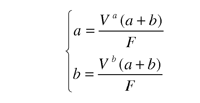


- Therefore, when the value of a is higher than a max it means that the constraining reaction Va in A is higher than

- In view of what explained above, in a preferred method for detecting the overload of a vehicle said interval of values which within Xc has to fall in order to avoid the overload of the vehicle is the interval [b max,a max], which is calculated according to the following system:


- In said method there may be a further stage in which the driver is alerted of the overload of the vehicle.
- In said method there may be a further stage in which the overload state and the time in which it remains in overload may be stored in specially provided storage means accessible to an authorized repairer.
- Typically the vehicles with more than two axles present two or more axles next to each other. The model of the beam put on two trolleys remains effective provided that each constraining reaction is considered to be the vectorial sum of the constraining reactions given by the single axles next to each other, this force being applied to the barycenter of the each single axle that has contributed to the vectorial sum.
- A device for detecting the overload of a vehicle, according to the method that is the object of the invention, comprises:
- storage means 1 of at least a pair of values defining a finite interval;
- signalling means 2 for the driver;
- elaboration means 3 with the function of:
- a. calculating the position Xc of the barycenter of a vehicle with two axles A and B along the longitudinal axis of the vehicle itself;
- b. comparing said value of Xc with said finite interval, and
- c. activating said signalling means for the driver, when Xc falls outside the interval. Further on, said device may comprise storage means, accessible to an authorized repairer, which may correspond with said storage means 1, in which the overloading events and the time in which a vehicle remains in an overload state may be stored.
- Means for the calculation of the position Xc of the barycenter of a vehicle are already known and comprise a system usually called ESP (Electronic Stability Program). For this reason, in a preferred embodiment of the device, said elaboration means 3 comprise said ESP system and further means with the function of:
- b. comparing said value of Xc with said finite interval, and
- c. activating said signalling means for the driver, when Xc falls outside the interval. The advantage is that the driver of a vehicle equipped with said device for detecting the overload has the possibility to reduce the load of the vehicle before damaging the vehicle itself and/or getting getting a fine from the police.
- The advantage is also that the manufacturer of a vehicle equipped with said device for detecting the overload has the possibility to verify an illegitimate use of the vehicle sold.
- The particular embodiments described here do not limit the scope of this invention which covers all the alternative embodiments defined by the claims.
Claims (11)
- Method for detecting the overload condition in a vehicle, in particular a commercial or industrial vehicle, comprising the following steps:- definition of a finite interval of values within which the position of the barycenter of a vehicle has to fall along its longitudinal axis, in various admissible load conditions;- detection of the position Xc of the barycenter along the longitudinal axis;- if Xc falls within said interval, the vehicle is not overloaded, otherwise the vehicle is overloaded.
- Method according to claim 1, in which said finite interval of values, to which said position Xc has to belong in order to avoid the overload of the vehicle, is empirically calculated making experiments of admissible loading of the vehicle.
- Method according to claim 1, in which said vehicle comprises two or more axles, and in which said finite interval of value to which said position Xc has to belong in order to avoid the overload of said vehicle with two axles A and B, is the interval [b max, a max] calculated according to the following system of equations:

where F is the overall weight of the vehicle with a full load,

- Method according to claim 3, in which said vehicle comprising two or more axles is treated as a vehicle with only two axles by adding up the constraining reactions of the single close up axle.
- Method according to claim 1, comprising also a subsequent stage of alert for the overload state of the vehicle.
- Method according to claim 1, comprising also a subsequent stage in which the overload state and the time in which the vehicle remains in an overload state may be stored in specially provided storage means, accessible from the outside of the vehicle.
- Device for detecting the overload condition of a vehicle comprising:- storage means (1) of at least a pair of values defining a finite interval;- signalling means (2) of the overload condition;- processing means (3) with the function of:a. calculating the position Xc of the barycenter of a vehicle with two or more axles along the longitudinal axis of the vehicle itself;b. comparing said value of Xc with said finite interval, andc. activating said signalling means (2), when said position Xc falls outside said finite interval.
- Device according to claim 7, in which said finite interval of values to which said position Xc has to belong in order to avoid the overload of said vehicle, treated as a vehicle with two axles A and B, is the interval [b max, a max] calculated according to the following system of equations:

where F is the overall weight of the vehicle with a full load,

- Device according to claim 7, in which said elaboration means (3) have also the function to store the overload state and the time in which the vehicle remains in an overload state in said storage means, accessible from the outside of the vehicle.
- Device according to claim 7, in which said processing means (3) comprise a control unit defining an ESP security system.
- Vehicle including a device for detecting the overload condition as in any of the claims from 7 to 10.
Priority Applications (1)
| Application Number | Priority Date | Filing Date | Title |
|---|---|---|---|
| EP07425757A EP2065689A1 (en) | 2007-11-28 | 2007-11-28 | Method and device for detecting the overload of a vehicle, in particular a commercial or industrial vehicle |
Applications Claiming Priority (1)
| Application Number | Priority Date | Filing Date | Title |
|---|---|---|---|
| EP07425757A EP2065689A1 (en) | 2007-11-28 | 2007-11-28 | Method and device for detecting the overload of a vehicle, in particular a commercial or industrial vehicle |
Publications (1)
| Publication Number | Publication Date |
|---|---|
| EP2065689A1 true EP2065689A1 (en) | 2009-06-03 |
Family
ID=39316160
Family Applications (1)
| Application Number | Title | Priority Date | Filing Date |
|---|---|---|---|
| EP07425757A Ceased EP2065689A1 (en) | 2007-11-28 | 2007-11-28 | Method and device for detecting the overload of a vehicle, in particular a commercial or industrial vehicle |
Country Status (1)
| Country | Link |
|---|---|
| EP (1) | EP2065689A1 (en) |
Cited By (3)
| Publication number | Priority date | Publication date | Assignee | Title |
|---|---|---|---|---|
| EP2192014A3 (en) * | 2008-11-26 | 2010-08-11 | Bertola, Alessandro | Device and process for preventing off-road vehicles from overturning |
| GB2543920A (en) * | 2015-10-27 | 2017-05-03 | Deere & Co | System and method for overload protection |
| CN109446606A (en) * | 2018-10-16 | 2019-03-08 | 中车株洲电力机车有限公司 | The optimizing method for disposing and its system of equipment under a kind of rail vehicle |
Citations (5)
| Publication number | Priority date | Publication date | Assignee | Title |
|---|---|---|---|---|
| GB1240890A (en) * | 1966-04-30 | 1971-07-28 | Vdo Luftfahrtgerate Werk Adolf | Apparatus for determining the position of the centre of gravity and/or the weight of an aircraft |
| GB2191868A (en) | 1986-05-22 | 1987-12-23 | Arcubos Systems Limited | Vehicle load display |
| EP1167094A1 (en) | 2000-06-20 | 2002-01-02 | Continental Aktiengesellschaft | Determination of the force on each wheel of a vehicle |
| WO2006043872A1 (en) * | 2004-10-18 | 2006-04-27 | Volvo Lastvagnar Ab | An axle load control system and a wheel base adjustment system |
| GB2424961A (en) | 2005-04-04 | 2006-10-11 | Pm Group Plc | Methods of load and axle measurement |
-
2007
- 2007-11-28 EP EP07425757A patent/EP2065689A1/en not_active Ceased
Patent Citations (5)
| Publication number | Priority date | Publication date | Assignee | Title |
|---|---|---|---|---|
| GB1240890A (en) * | 1966-04-30 | 1971-07-28 | Vdo Luftfahrtgerate Werk Adolf | Apparatus for determining the position of the centre of gravity and/or the weight of an aircraft |
| GB2191868A (en) | 1986-05-22 | 1987-12-23 | Arcubos Systems Limited | Vehicle load display |
| EP1167094A1 (en) | 2000-06-20 | 2002-01-02 | Continental Aktiengesellschaft | Determination of the force on each wheel of a vehicle |
| WO2006043872A1 (en) * | 2004-10-18 | 2006-04-27 | Volvo Lastvagnar Ab | An axle load control system and a wheel base adjustment system |
| GB2424961A (en) | 2005-04-04 | 2006-10-11 | Pm Group Plc | Methods of load and axle measurement |
Non-Patent Citations (1)
| Title |
|---|
| ANONYMOUS: "Centre of gravity indicator for load vehicles", RESEARCH DISCLOSURE, MASON PUBLICATIONS, HAMPSHIRE, GB, vol. 203, no. 14, March 1981 (1981-03-01), XP007107735, ISSN: 0374-4353 * |
Cited By (5)
| Publication number | Priority date | Publication date | Assignee | Title |
|---|---|---|---|---|
| EP2192014A3 (en) * | 2008-11-26 | 2010-08-11 | Bertola, Alessandro | Device and process for preventing off-road vehicles from overturning |
| GB2543920A (en) * | 2015-10-27 | 2017-05-03 | Deere & Co | System and method for overload protection |
| US9815479B2 (en) | 2015-10-27 | 2017-11-14 | Deere & Company | System and method for overload protection |
| GB2543920B (en) * | 2015-10-27 | 2021-10-13 | Deere & Co | System and method for overload protection |
| CN109446606A (en) * | 2018-10-16 | 2019-03-08 | 中车株洲电力机车有限公司 | The optimizing method for disposing and its system of equipment under a kind of rail vehicle |
Similar Documents
| Publication | Publication Date | Title |
|---|---|---|
| US8966962B2 (en) | Measurement device of position of center of gravity of vehicle to be measured on truck scale and truck scale | |
| US6363331B1 (en) | Weight distribution monitor | |
| US8874329B2 (en) | Method and device for monitoring the stability of a loading crane mounted on a vehicle | |
| EP2005140B1 (en) | Method for collecting information on road surface slipperiness | |
| US7573375B2 (en) | Rollover prediction and warning method | |
| JP5993804B2 (en) | Tire contact state estimation method | |
| EP3562702B1 (en) | Arrangement for determining maximum allowable torque | |
| JP5265440B2 (en) | Load weight estimation device | |
| US8326480B2 (en) | Method and device for monitoring the state of tires | |
| JP2005518987A (en) | How to determine the maximum coefficient of friction | |
| KR20120109984A (en) | Apparatus, method and computer-readable recording medium having program recorded therein for vehicle mass estimation, and apparatus, method and computer-readable recording medium having program recorded therein for detecting decrease in tire air pressure | |
| JP5729863B2 (en) | Traveling vehicle center of gravity measurement system | |
| KR100640175B1 (en) | Vehicle rollover control system and method | |
| TW201630764A (en) | Method for determining the angle of inclination of a two-wheeled vehicle | |
| US20240034303A1 (en) | Vehicle load regulating system and method thereof | |
| US6834222B2 (en) | Tire imbalance detection system and method using anti-lock brake wheel speed sensors | |
| CN101585349B (en) | Method and system for vehicle rollover detection | |
| Guizhen et al. | Real-time bus rollover prediction algorithm with road bank angle estimation | |
| JP2002156312A (en) | Indicator for misalignment of axle and tire abrasion | |
| JP2017044706A (en) | Vehicle driving support device | |
| CN112270828A (en) | Vehicle early warning method and device, electronic equipment and vehicle | |
| CN113002552A (en) | Rollover discrimination method based on vehicle roll angle | |
| KR101760456B1 (en) | Method for controlling overloaded vehicle | |
| WO2014109226A1 (en) | Automated guided vehicle guidance system and automated guided vehicle guidance method | |
| JP5749106B2 (en) | Road surface state estimation method and road surface state estimation device |
Legal Events
| Date | Code | Title | Description |
|---|---|---|---|
| PUAI | Public reference made under article 153(3) epc to a published international application that has entered the european phase |
Free format text: ORIGINAL CODE: 0009012 |
|
| AK | Designated contracting states |
Kind code of ref document: A1 Designated state(s): AT BE BG CH CY CZ DE DK EE ES FI FR GB GR HU IE IS IT LI LT LU LV MC MT NL PL PT RO SE SI SK TR |
|
| AX | Request for extension of the european patent |
Extension state: AL BA HR MK RS |
|
| 17P | Request for examination filed |
Effective date: 20091201 |
|
| AKX | Designation fees paid |
Designated state(s): AT BE BG CH CY CZ DE DK EE ES FI FR GB GR HU IE IS IT LI LT LU LV MC MT NL PL PT RO SE SI SK TR |
|
| 17Q | First examination report despatched |
Effective date: 20100115 |
|
| APBK | Appeal reference recorded |
Free format text: ORIGINAL CODE: EPIDOSNREFNE |
|
| APBN | Date of receipt of notice of appeal recorded |
Free format text: ORIGINAL CODE: EPIDOSNNOA2E |
|
| APAF | Appeal reference modified |
Free format text: ORIGINAL CODE: EPIDOSCREFNE |
|
| APBT | Appeal procedure closed |
Free format text: ORIGINAL CODE: EPIDOSNNOA9E |
|
| STAA | Information on the status of an ep patent application or granted ep patent |
Free format text: STATUS: THE APPLICATION HAS BEEN REFUSED |
|
| 18R | Application refused |
Effective date: 20151023 |