EP2065188A2 - Printing machine - Google Patents
Printing machine Download PDFInfo
- Publication number
- EP2065188A2 EP2065188A2 EP08003359A EP08003359A EP2065188A2 EP 2065188 A2 EP2065188 A2 EP 2065188A2 EP 08003359 A EP08003359 A EP 08003359A EP 08003359 A EP08003359 A EP 08003359A EP 2065188 A2 EP2065188 A2 EP 2065188A2
- Authority
- EP
- European Patent Office
- Prior art keywords
- panel
- unit
- printing
- printing press
- magnets
- Prior art date
- Legal status (The legal status is an assumption and is not a legal conclusion. Google has not performed a legal analysis and makes no representation as to the accuracy of the status listed.)
- Withdrawn
Links
- 238000007639 printing Methods 0.000 title claims abstract description 110
- 239000000758 substrate Substances 0.000 description 8
- 238000010586 diagram Methods 0.000 description 7
- 230000004048 modification Effects 0.000 description 5
- 238000012986 modification Methods 0.000 description 5
- 238000005516 engineering process Methods 0.000 description 3
- 229910000831 Steel Inorganic materials 0.000 description 2
- 239000002184 metal Substances 0.000 description 2
- 239000010959 steel Substances 0.000 description 2
- 241000252254 Catostomidae Species 0.000 description 1
- 241000755266 Kathetostoma giganteum Species 0.000 description 1
- 238000004140 cleaning Methods 0.000 description 1
- 239000011248 coating agent Substances 0.000 description 1
- 238000000576 coating method Methods 0.000 description 1
- 239000003086 colorant Substances 0.000 description 1
- 238000010276 construction Methods 0.000 description 1
- 238000007646 gravure printing Methods 0.000 description 1
- 238000007645 offset printing Methods 0.000 description 1
- 239000011347 resin Substances 0.000 description 1
- 229920005989 resin Polymers 0.000 description 1
Images



Classifications
-
- B—PERFORMING OPERATIONS; TRANSPORTING
- B41—PRINTING; LINING MACHINES; TYPEWRITERS; STAMPS
- B41F—PRINTING MACHINES OR PRESSES
- B41F13/00—Common details of rotary presses or machines
- B41F13/0024—Frames
Definitions
- the present invention relates to a printing press.
- Printing machines developed in recent years include a printing unit equipped with an operation panel (hereinafter, “panel”) for controlling the printing unit.
- panel an operation panel
- Japanese Patent Application Laid-Open No. H11-291462 discloses a conventional technology related to such a printing press (gravure printing press).
- the printing press includes a plurality of printing units arranged at a predetermined interval.
- Each of the printing units includes a printing mechanism that includes a cylinder and various printing auxiliaries, and a control operation unit of the printing mechanism.
- the printing mechanism is arranged in such a manner that the longitudinal side of the printing mechanism is orthogonal to a direction of arrangement of the printing unit.
- the control operation unit is arranged on an end portion of the longitudinal side of the printing mechanism, and includes a panel having various operation switches.
- the panel is arranged on the surface of the control operation unit, which is inclined from a plane orthogonal to the longitudinal direction of the printing mechanism.
- the panel is fixed to the printing unit with screws or nuts. Therefore, upon replacement of the panel, it is necessary to remove screws or the like. Therefore, the replacement of a panel is cumbersome and takes a long time.
- a printing press that includes a plurality of units including a printing unit, a feeder unit, and a delivery unit. At least one of the units includes a panel for at least operating the unit or displaying the state of the unit. The panel is attached to the unit with a magnet.
- Fig. 1 is a schematic diagram of a printing press 1 according to an embodiment of the present invention.
- the printing press 1 is, for example, a sheet-fed printing press, and includes a feed mechanism 2, a printing mechanism 3, and a delivery mechanism 4 (see Fig. 1 ).
- the feed mechanism 2 includes a feeder unit 21.
- the feeder unit 21 picks up a sheet set for printing, and feeds the sheet to the printing mechanism 3. Specifically, a plurality of sheets are stacked and set in the feeder unit 21, and each of the sheets is sequentially picked up and fed to the printing mechanism 3.
- the printing mechanism 3 includes a plurality of the printing units 31.
- the printing units 31 correspond to four different colors of C (cyan), M (magenta), Y (yellow), and BL (black), respectively, and aligned along a path for conveying a sheet S.
- the printing mechanism 3 performs a color printing by causing the printing units 31 to sequentially perform offset printing on a sheet fed from the feed mechanism 2.
- the delivery mechanism 4 includes a delivery unit 41.
- the delivery unit 41 conveys a printed sheet obtained from the printing mechanism 3 to delivery the printed sheet.
- the printing press 1 can include a coater unit (not shown) that performs coating on a sheet or other units (not shown) in addition to the feeder unit 21, the printing unit 31, and the delivery unit 41.
- the units to be added to the printing press 1 can be configured in the same manner as the units 21, 31, and 41.
- the printing mechanism 3 includes a plurality of panels 32 as shown in Fig. 1 .
- the panels 32 include an operation panel for controlling and operating the printing units 31, and a display panel for displaying the states of the printing units 31.
- the panels 32 are arranged on the printing units 31, respectively. Specifically, each of the panels 32 is arranged on an aisle side of a body portion 311 of each of the printing units 31.
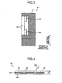
- Each of the panels 32 includes a substrate 321, a panel portion 322, and a panel sheet 323 as shown in Fig. 4 .
- the substrate 321 is used for operating corresponding one of the printing units 31, and connected to the printing unit 31 via a cable 324.
- the substrate 321 includes a plurality of buttons or switches.
- the panel portion 322 is formed of a steel plate or the like, and forms a body of the panel 32.
- the panel portion 322 includes holes corresponding to switches on the substrate 321,
- the panel sheet 323 covers an operation screen (surface) of the panel 32.
- the panel 32 is formed of layers of the substrate 321, the panel portion 322, and the panel sheet 323.
- the panel 32 is in the form of a substantially square plate, and is arranged such that the panel sheet 323 faces an aisle side of the printing mechanism 3.
- a thickness "d" of the panel 32 is about 60 millimeters.
- Each of the panels 32 is attached to each of the printing units 31 with magnets 33 as sown in Figs. 2 and 3 . Specifically, the panel 32 is held and fixed to the printing unit 31 by the attractive force of the magnets 33. In the embodiment, each of the panels 32 is attached to the body portion 311 of each of the printing units 31 with the four magnets 33.
- the panel 32 includes the substrate 321, the substrate 321 is not necessarily required.
- the panel portion can include an operation buttons or is formed only of a display panel, and connected to a printing unit via a cable without a substrate.
- the panel 32 is attached to the printing unit 31 with the magnets 33 by the attractive force thereof. Therefore, it is possible to easily replace the panel 32 (attach/remove the panel 32 to/from the printing unit 31) with less time. Moreover, a structure for fitting the panel 32 is simplified, which improves appearance of the printing unit 31.
- a panel can be provided on the feeder unit 21 or the delivery unit 41.
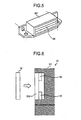
- a concave portion 312 is formed in the printing unit 31, and the panel 32 is fitted in the concave portion 312 as shown in Fig. 6 . That is, it is preferable that the panel 32 be held by the attractive force of the magnet 33 while fitted in the concave portion 312. With this configuration, the panel 32 can be stably set compared with a configuration where a panel is attached to a surface of a printing unit.
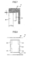
- a space “t" between the concave portion 312 and the panel 32 fitted in the concave portion 312 be equal to or smaller than one millimeter (see Fig. 7 ). If the space “t" between the concave portion 312 and the panel 32 is set to such a small value, the panel 32 is firmly fitted to the concave portion 312. Thus, the panel 32 can be stably held. Specifically, when the printing press 1 is in operation, it causes the printing unit 31 to vibrate. Therefore, if the space "t" is maintained in an appropriate range, it is possible to effectively prevent the panel 32 from coming off or being broken by the vibration.
- the panel 32 is in the form of a substantially square plate (see Fig. 4 ).
- the concave portion 312 is in substantially the same shape as the circumference of the panel 32 (see Fig. 6 ) so that the panel 32 is fitted in the concave portion 312.
- the space “t" between the circumference of the panel 32, which corresponds to the upper surface of the panel 32 in the vertical direction, and the inner surface of the concave portion 312 is set equal to or narrower than one millimeter (see Fig. 7 ).
- the bottom surface of the panel 32 is in contact with the inner surface of the concave portion 312. In this manner, the panel 32 is firmly fitted to the concave portion 312.
- the magnets 33 is arranged inside the concave portion 312 as shown in Fig. 6 . That is, it is preferable that the magnets 33 be arranged inside the printing unit 31 (inside the concave portion 312) so that the panel 32 can be held by the attractive force of the magnets 33. With this, the magnets is not exposed to the outside of the printing unit. Thus, appearance of the printing unit can be improved.
- the four magnets 33 are attached to the inner surface of the concave portion 312 (see Fig. 6 ).
- the magnets 33 are in contact with the panel 32 in the concave portion 312, holding the panel 32 by the attractive force thereof.
- the magnets 33 are covered by the panel 32 not to be exposed to the outside of the printing unit 31.
- the front surface (operation surface) of the panel 32 is in the same plane as the surface of the printing unit 31 (see Fig. 3 ), or in the inner side from the surface of the printing unit 31 (not shown).
- the panel 32 be embedded in the surface of the printing unit 31 so that a portion of the panel 32 does not protrude from the surface of the printing unit 31.
- the panel 32 is hardly considered as an obstacle. It is often the case that the panel 32 is arranged on an aisle side of the printing unit 31. Therefore, if a portion of the panel 32 protrudes from the surface of the printing unit 31, this portion may be an obstacle to those who passing the aisle,
- the panel 32 is arranged in such a manner that the front surface of the panel 32 is in substantially the same plane as the surface of the printing unit 31 (the surface of the printing unit 31 is flat) as shown in Fig. 3 . Accordingly, the panel 32 constitutes no obstacle to a person around the printing press 1. In addition, appearance of the printing press 1 is improved. Specifically, the panel 32 is held from the inner side of the printing unit 31 by the attractive force of the magnets 33 in the printing press 1. Therefore, it is easy to arrange the panel 32 in a flat manner as described above compared with a configuration where a panel is fixed by screws.
- a notched portion 34 for inserting tools is arranged on a fitted portion between the panel 32 and the concave portion 312 as shown in Figs. 8 and 9 .
- a tool e.g., a flathead screwdriver
- the panel 32 is fitted in the concave portion 312, and the front surface of the panel 32 is in the same plane as the surface of the printing unit 31 (see Fig. 3 ) or the front surface of the panel 32 is in the inner side from the surface of the printing unit 31 (not shown), it is difficult to remove the panel 32. If the notched portion 34 for inserting tools is arranged on the fitted portion between the panel 32 and the concave portion 312, the replacement of the panel 32 can be much easier.
- the front surface of the panel 32 is in the same plane as the surface of the printing unit 31, and the notched portion 34 is arranged at the corner of the concave portion 312 as shown in Fig. 8 .
- the notched portion 34 can be arranged at a corner of the panel 32 as shown in Fig. 9 .
- the magnets 33 are fixed on the printing unit 31 as shown in Fig. 6 .
- the magnets 33 be fixed on the printing unit 31 to hold the panel 32 by the attractive force thereof.
- the panel 32 can be removed from the printing unit 31 without removing other units. Consequently, the replacement of the panel 32 can be facilitated.
- the magnets 33 are fixed to the panel 32, the magnets are removed with the panel 32 from the printing unit 31. In such a case, the magnets 33 may pick up metal components around them, which interrupts the replacement work for the panel 32.
- the backside of the panel 32 adhere to the magnets 33 as shown in Fig. 3 .
- the magnets 33 are not exposed from the front surface of the panel 32 (from the side of the panel sheet 323). As a result, appearance of the printing unit can be improved.
- the four magnets 33 are attached to the inner surface of the concave portion 312 (see Fig. 6 ).
- the panel 32 is held by the attractive force of the magnets 33.
- the positions of the magnets 33 and the panel 32 are determined so that the backside of the panel 32 adheres to the magnets 33 (see Figs. 2 and 3 ).
- the panel 32 includes the panel portion 322 made of steel, and the back end portions of the panel portion 322 adhere to the magnets 33 (see Fig. 4 ).
- the magnets 33 are not exposed to the outside of the printing unit 31 when the panel 32 is set.
- the magnets 33 are fixed to the printing unit 31 by screws. With this, it is possible to stably fix the magnets 33 to the printing unit 31 in a simple manner.
- the magnets 33 are held in a magnet case 331 made of resin (see Fig. 5 ).
- the magnet case 331 is attached to the body portion 311 of the printing unit 31 by screws such that the magnets 33 are fixed to the body portion 311 (see Figs. 3 and 6 ).
- an engaging member 313 can be arranged on the printing unit 31 so that the magnets 33 engages the engaging member 313 to be fixed as shown in Figs. 10 and 11 .
- the magnets 33 can also be fixed to the printing unit 31 in a simple manner.
- each of the magnets 33 includes a hook 332.
- the body portion 311 of the printing unit 31 is in the form of sheet metal, and the engaging member 313 in the form of a hook is formed on the body portion 311.
- the magnets 33 are fixed by the hook 332 that engages the engaging member 313. With this configuration, attachment of the magnets 33 can be simplified compared with a configuration where the magnets 33 are fixed with screws.
- the magnets 33 are permanent magnets. With such permanent magnets, it is possible to stably hold the panel 32 in a simple configuration with less cost. Specifically, if the magnets 33 are electromagnets, the panel 32 may come off when power outage occurs. If suckers (not shown) are used instead of the magnets 33, it is difficult to stably hold a panel for a long time.
- the magnets 33 are in an elongated shape, and their longitudinal sides are arranged along the vertical direction (see Fig. 2 ).
- the panel 32 can be effectively held in the vertical direction. Consequently, it is possible to stably hold the panel 32.
- the printing unit 31 vibrates in the vertical direction when the printing press 1 is in operation. Therefore, by firmly holding the panel 32 in the vertical direction, it is possible to prevent the panel 32 from being coming off.
- the magnets 33 can be arranged in such a manner that their longitudinal sides come along the horizontal direction as shown in Fig. 12 . With this configuration, it is also possible to stably hold the panel 32.
- the number of the magnets 33 is cited merely by way of example and without limitation.
- the strength of the magnets 33 can be changed as appropriate depending on the weight of the panel 32.
- a panel can be attached to a unit while stably held by the attractive force of a magnet with less cost, and can also be replaced in a simple manner.
- the magnet is arranged inside the unit and hardly viewed from the outside, Therefore, appearance of the unit can be improved.
- the panel is embedded in a surface of the unit so that any portion of the panel does not protrude from the surface of the unit.
- the panel provides no obstacle to operation.
Landscapes
- Engineering & Computer Science (AREA)
- Mechanical Engineering (AREA)
- Casings For Electric Apparatus (AREA)
- Accessory Devices And Overall Control Thereof (AREA)
- Inking, Control Or Cleaning Of Printing Machines (AREA)
Abstract
A printing press (1) includes a printing unit (31), a feeder unit (21), and a delivery unit (41). At least one of the units (21, 31, 41) is provided with a panel (32) for either or both operating the unit (21, 31, 41) and displaying a state of the unit (21, 31, 41). The panel (32) is attached to the unit (21, 31, 41) with a magnet (33), and is held by the attractive force of the magnet (33).
Description
- The present invention relates to a printing press.
- Printing machines developed in recent years include a printing unit equipped with an operation panel (hereinafter, "panel") for controlling the printing unit.
- Japanese Patent Application Laid-Open No.
H11-291462 - However, in the conventional technology, the panel is fixed to the printing unit with screws or nuts. Therefore, upon replacement of the panel, it is necessary to remove screws or the like. Therefore, the replacement of a panel is cumbersome and takes a long time.
- It is an object of the present invention to at least partially solve the problems in the conventional technology.
- According to an aspect of the present invention, there is provided a printing press that includes a plurality of units including a printing unit, a feeder unit, and a delivery unit. At least one of the units includes a panel for at least operating the unit or displaying the state of the unit. The panel is attached to the unit with a magnet.
- The above and other objects, features, advantages and technical and industrial significance of this invention will be better understood by reading the following detailed description of presently preferred embodiments of the invention, when considered in connection with the accompanying drawings.
-
-
Fig. 1 is a schematic diagram of a printing press according to an embodiment of the present invention; -
Figs. 2 to 7 are schematic diagrams for explaining a fixing structure for fixing a panel shown inFig. 1 ; -
Fig. 8 is a schematic diagram of a modification of the fixing structure; -
Fig. 9 is a schematic diagram of another modification of the fixing structure; -
Figs. 10 and11 are schematic diagrams of still another modification of the fixing structure; and -
Fig. 12 is a schematic diagram of still another modification of the fixing structure. - Exemplary embodiments of the present invention are explained in detail below with reference to the accompanying drawings.
-
Fig. 1 is a schematic diagram of aprinting press 1 according to an embodiment of the present invention. Theprinting press 1 is, for example, a sheet-fed printing press, and includes afeed mechanism 2, aprinting mechanism 3, and a delivery mechanism 4 (seeFig. 1 ). Thefeed mechanism 2 includes afeeder unit 21. Thefeeder unit 21 picks up a sheet set for printing, and feeds the sheet to theprinting mechanism 3. Specifically, a plurality of sheets are stacked and set in thefeeder unit 21, and each of the sheets is sequentially picked up and fed to theprinting mechanism 3. Theprinting mechanism 3 includes a plurality of theprinting units 31. Theprinting units 31 correspond to four different colors of C (cyan), M (magenta), Y (yellow), and BL (black), respectively, and aligned along a path for conveying a sheet S. Theprinting mechanism 3 performs a color printing by causing theprinting units 31 to sequentially perform offset printing on a sheet fed from thefeed mechanism 2. The delivery mechanism 4 includes adelivery unit 41. Thedelivery unit 41 conveys a printed sheet obtained from theprinting mechanism 3 to delivery the printed sheet. - The
printing press 1 can include a coater unit (not shown) that performs coating on a sheet or other units (not shown) in addition to thefeeder unit 21, theprinting unit 31, and thedelivery unit 41. The units to be added to theprinting press 1 can be configured in the same manner as theunits - The
printing mechanism 3 includes a plurality ofpanels 32 as shown inFig. 1 . Examples of thepanels 32 include an operation panel for controlling and operating theprinting units 31, and a display panel for displaying the states of theprinting units 31. Thepanels 32 are arranged on theprinting units 31, respectively. Specifically, each of thepanels 32 is arranged on an aisle side of abody portion 311 of each of theprinting units 31. - Each of the
panels 32 includes asubstrate 321, apanel portion 322, and apanel sheet 323 as shown inFig. 4 . Thesubstrate 321 is used for operating corresponding one of theprinting units 31, and connected to theprinting unit 31 via acable 324. Thesubstrate 321 includes a plurality of buttons or switches. Thepanel portion 322 is formed of a steel plate or the like, and forms a body of thepanel 32. Thepanel portion 322 includes holes corresponding to switches on thesubstrate 321, Thepanel sheet 323 covers an operation screen (surface) of thepanel 32. Thepanel 32 is formed of layers of thesubstrate 321, thepanel portion 322, and thepanel sheet 323. Thepanel 32 is in the form of a substantially square plate, and is arranged such that thepanel sheet 323 faces an aisle side of theprinting mechanism 3. A thickness "d" of thepanel 32 is about 60 millimeters. - Each of the
panels 32 is attached to each of theprinting units 31 withmagnets 33 as sown inFigs. 2 and3 . Specifically, thepanel 32 is held and fixed to theprinting unit 31 by the attractive force of themagnets 33. In the embodiment, each of thepanels 32 is attached to thebody portion 311 of each of theprinting units 31 with the fourmagnets 33. - While, in the embodiment, the
panel 32 includes thesubstrate 321, thesubstrate 321 is not necessarily required. Specifically, the panel portion can include an operation buttons or is formed only of a display panel, and connected to a printing unit via a cable without a substrate. - As described above, the
panel 32 is attached to theprinting unit 31 with themagnets 33 by the attractive force thereof. Therefore, it is possible to easily replace the panel 32 (attach/remove thepanel 32 to/from the printing unit 31) with less time. Moreover, a structure for fitting thepanel 32 is simplified, which improves appearance of theprinting unit 31. - On the other hand, if a panel is fixed to a printing unit by screws or nuts, such screw need to be removed upon replacement of the panel. Therefore, replacement of the panel is cumbersome, and takes a long time. Besides, such a screw may drop during the operation and damage other units. Moreover, such screws impair the appearance of a printing unit. Furthermore, it is difficult to remove dirt on a portion where a screw is arranged upon cleaning the panel, making it difficult to clean a printing press.
- while, in the embodiment, the
panel 32 is provided on theprinting unit 31, a panel can be provided on thefeeder unit 21 or thedelivery unit 41. - Preferably, a
concave portion 312 is formed in theprinting unit 31, and thepanel 32 is fitted in theconcave portion 312 as shown inFig. 6 . That is, it is preferable that thepanel 32 be held by the attractive force of themagnet 33 while fitted in theconcave portion 312. With this configuration, thepanel 32 can be stably set compared with a configuration where a panel is attached to a surface of a printing unit. - It is also preferable that a space "t" between the
concave portion 312 and thepanel 32 fitted in theconcave portion 312 be equal to or smaller than one millimeter (seeFig. 7 ). If the space "t" between theconcave portion 312 and thepanel 32 is set to such a small value, thepanel 32 is firmly fitted to theconcave portion 312. Thus, thepanel 32 can be stably held. Specifically, when theprinting press 1 is in operation, it causes theprinting unit 31 to vibrate. Therefore, if the space "t" is maintained in an appropriate range, it is possible to effectively prevent thepanel 32 from coming off or being broken by the vibration. - Specifically, the
panel 32 is in the form of a substantially square plate (seeFig. 4 ). Theconcave portion 312 is in substantially the same shape as the circumference of the panel 32 (seeFig. 6 ) so that thepanel 32 is fitted in theconcave portion 312. The space "t" between the circumference of thepanel 32, which corresponds to the upper surface of thepanel 32 in the vertical direction, and the inner surface of theconcave portion 312 is set equal to or narrower than one millimeter (seeFig. 7 ). In addition, the bottom surface of thepanel 32 is in contact with the inner surface of theconcave portion 312. In this manner, thepanel 32 is firmly fitted to theconcave portion 312. - Preferably, the
magnets 33 is arranged inside theconcave portion 312 as shown inFig. 6 . That is, it is preferable that themagnets 33 be arranged inside the printing unit 31 (inside the concave portion 312) so that thepanel 32 can be held by the attractive force of themagnets 33. With this, the magnets is not exposed to the outside of the printing unit. Thus, appearance of the printing unit can be improved. - Specifically, the four
magnets 33 are attached to the inner surface of the concave portion 312 (seeFig. 6 ). Themagnets 33 are in contact with thepanel 32 in theconcave portion 312, holding thepanel 32 by the attractive force thereof. Themagnets 33 are covered by thepanel 32 not to be exposed to the outside of theprinting unit 31. - Preferably, the front surface (operation surface) of the
panel 32 is in the same plane as the surface of the printing unit 31 (seeFig. 3 ), or in the inner side from the surface of the printing unit 31 (not shown). Specifically, it is preferable that thepanel 32 be embedded in the surface of theprinting unit 31 so that a portion of thepanel 32 does not protrude from the surface of theprinting unit 31. With this configuration, thepanel 32 is hardly considered as an obstacle. It is often the case that thepanel 32 is arranged on an aisle side of theprinting unit 31. Therefore, if a portion of thepanel 32 protrudes from the surface of theprinting unit 31, this portion may be an obstacle to those who passing the aisle, - According to the embodiment, the
panel 32 is arranged in such a manner that the front surface of thepanel 32 is in substantially the same plane as the surface of the printing unit 31 (the surface of theprinting unit 31 is flat) as shown inFig. 3 . Accordingly, thepanel 32 constitutes no obstacle to a person around theprinting press 1. In addition, appearance of theprinting press 1 is improved. Specifically, thepanel 32 is held from the inner side of theprinting unit 31 by the attractive force of themagnets 33 in theprinting press 1. Therefore, it is easy to arrange thepanel 32 in a flat manner as described above compared with a configuration where a panel is fixed by screws. - Preferably, a notched
portion 34 for inserting tools is arranged on a fitted portion between thepanel 32 and theconcave portion 312 as shown inFigs. 8 and9 . With this configuration, upon replacement of thepanel 32, a tool (e.g., a flathead screwdriver) is inserted into the notchedportion 34 to remove thepanel 32 from theconcave portion 312. Therefore, it is possible to facilitate the replacement of thepanel 32. Because thepanel 32 is fitted in theconcave portion 312, and the front surface of thepanel 32 is in the same plane as the surface of the printing unit 31 (seeFig. 3 ) or the front surface of thepanel 32 is in the inner side from the surface of the printing unit 31 (not shown), it is difficult to remove thepanel 32. If the notchedportion 34 for inserting tools is arranged on the fitted portion between thepanel 32 and theconcave portion 312, the replacement of thepanel 32 can be much easier. - Specifically, the front surface of the
panel 32 is in the same plane as the surface of theprinting unit 31, and the notchedportion 34 is arranged at the corner of theconcave portion 312 as shown inFig. 8 . The notchedportion 34 can be arranged at a corner of thepanel 32 as shown inFig. 9 . Upon replacement of thepanel 32, a tool is inserted into the notchedportion 34 to remove thepanel 32. - Preferably, the
magnets 33 are fixed on theprinting unit 31 as shown inFig. 6 . Specifically, it is preferable that themagnets 33 be fixed on theprinting unit 31 to hold thepanel 32 by the attractive force thereof. With this configuration, thepanel 32 can be removed from theprinting unit 31 without removing other units. Consequently, the replacement of thepanel 32 can be facilitated. Specifically, if themagnets 33 are fixed to thepanel 32, the magnets are removed with thepanel 32 from theprinting unit 31. In such a case, themagnets 33 may pick up metal components around them, which interrupts the replacement work for thepanel 32. - It is also preferable that the backside of the
panel 32 adhere to themagnets 33 as shown inFig. 3 . With this configuration, when thepanel 32 is set, themagnets 33 are not exposed from the front surface of the panel 32 (from the side of the panel sheet 323). As a result, appearance of the printing unit can be improved. - In the embodiment, the four
magnets 33 are attached to the inner surface of the concave portion 312 (seeFig. 6 ). Thepanel 32 is held by the attractive force of themagnets 33. The positions of themagnets 33 and thepanel 32 are determined so that the backside of thepanel 32 adheres to the magnets 33 (seeFigs. 2 and3 ). Specifically, thepanel 32 includes thepanel portion 322 made of steel, and the back end portions of thepanel portion 322 adhere to the magnets 33 (seeFig. 4 ). As a result, themagnets 33 are not exposed to the outside of theprinting unit 31 when thepanel 32 is set. - Sides of the panel 32 (the circumference of the
panel 32 viewed from the front surface side of the panel 32) can adhere to themagnets 33. With this configuration, thepanel 32 can also be properly held by themagnets 33. - Preferably, the
magnets 33 are fixed to theprinting unit 31 by screws. With this, it is possible to stably fix themagnets 33 to theprinting unit 31 in a simple manner. - In the embodiment, the
magnets 33 are held in amagnet case 331 made of resin (seeFig. 5 ). Themagnet case 331 is attached to thebody portion 311 of theprinting unit 31 by screws such that themagnets 33 are fixed to the body portion 311 (seeFigs. 3 and6 ). - Alternatively, an engaging
member 313 can be arranged on theprinting unit 31 so that themagnets 33 engages the engagingmember 313 to be fixed as shown inFigs. 10 and11 . With this configuration, themagnets 33 can also be fixed to theprinting unit 31 in a simple manner. - Specifically, in
Figs. 10 and11 , each of themagnets 33 includes ahook 332. Thebody portion 311 of theprinting unit 31 is in the form of sheet metal, and the engagingmember 313 in the form of a hook is formed on thebody portion 311. Themagnets 33 are fixed by thehook 332 that engages the engagingmember 313. With this configuration, attachment of themagnets 33 can be simplified compared with a configuration where themagnets 33 are fixed with screws. - Preferably, the
magnets 33 are permanent magnets. With such permanent magnets, it is possible to stably hold thepanel 32 in a simple configuration with less cost. Specifically, if themagnets 33 are electromagnets, thepanel 32 may come off when power outage occurs. If suckers (not shown) are used instead of themagnets 33, it is difficult to stably hold a panel for a long time. - Preferably, the
magnets 33 are in an elongated shape, and their longitudinal sides are arranged along the vertical direction (seeFig. 2 ). With this configuration, thepanel 32 can be effectively held in the vertical direction. Consequently, it is possible to stably hold thepanel 32. Specifically, theprinting unit 31 vibrates in the vertical direction when theprinting press 1 is in operation. Therefore, by firmly holding thepanel 32 in the vertical direction, it is possible to prevent thepanel 32 from being coming off. - The
magnets 33 can be arranged in such a manner that their longitudinal sides come along the horizontal direction as shown inFig. 12 . With this configuration, it is also possible to stably hold thepanel 32. - While, in the embodiment, the four
magnets 33 are arranged, the number of themagnets 33 is cited merely by way of example and without limitation. The strength of themagnets 33 can be changed as appropriate depending on the weight of thepanel 32. - As set forth hereinabove, according to an embodiment of the present invention, a panel can be attached to a unit while stably held by the attractive force of a magnet with less cost, and can also be replaced in a simple manner.
- Moreover, the magnet is arranged inside the unit and hardly viewed from the outside, Therefore, appearance of the unit can be improved.
- Furthermore, the panel is embedded in a surface of the unit so that any portion of the panel does not protrude from the surface of the unit. Thus, the panel provides no obstacle to operation.
- Although the invention has been described with respect to a specific embodiment for a complete and clear disclosure, the appended claims are not to be thus limited but are to be construed as embodying all modifications and alternative constructions within the scope of the claims.
Claims (12)
- A printing press that includes a plurality of units (21, 31, 41), the units (21, 31, 41) including a printing unit (31), a feeder unit (21), and a delivery unit (41), wherein
at least one of the units (21, 31, 41) includes a panel (32) for at least operating the unit (21, 31, 41) or displaying a state of the unit (21, 31, 41), and
the panel (32) is attached to the unit (21, 31, 41) with a magnet (33). - The printing press according to claim 1, wherein
the unit (21, 31, 41) includes a concave portion (312), and
the panel (32) is fitted to the concave portion (312). - The printing press according to claim 2, wherein a space between the concave portion (312) and the panel (32) flitted to the concave portion (312) is equal to or less than one millimeter.
- The printing press according to claim 2 or 3, wherein the magnet (33) is arranged inside the concave portion (312)
- The printing press according to any one of claims 2 to 4, wherein a front surface of the panel (32) is in substantially a same plane as a surface of the unit (21, 31, 41), or the front surface of the panel (32) is recessed from the surface of the unit (21, 31, 41).
- The printing press according to any one of claims 2 to 5, wherein a notched portion (34) for inserting a tool is arranged on a portion where the panel (32) is fitted to the concave portion (312).
- The printing press according to any one of claims 1 to 6, wherein the magnet (33) is fixed to the unit (21, 31, 41) .
- The printing press according to claim 7, wherein the panel (32) is configured such that a back surface of the panel (32) is attached to the magnet (33).
- The printing press according to claim 7 or 8, wherein the magnet (33) is fixed to the unit (21, 31, 41) with a screw.
- The printing press according to claim 8 or 9, wherein
an engaging member (313) is arranged on the unit (21, 31, 41), and
the magnet (33) is fixed by engaging the engaging member (313). - The printing press according to any one of claims 1 to 10, wherein the magnet (33) is a permanent magnet.
- The printing press according to any one of claims 1 to 11, wherein the magnet (33) is in an elongated shape, and is arranged such that a longitudinal side of the magnet (33) extends along a vertical direction.
Applications Claiming Priority (1)
| Application Number | Priority Date | Filing Date | Title |
|---|---|---|---|
| JP2007244517A JP2009073063A (en) | 2007-09-20 | 2007-09-20 | Printer |
Publications (1)
| Publication Number | Publication Date |
|---|---|
| EP2065188A2 true EP2065188A2 (en) | 2009-06-03 |
Family
ID=40471803
Family Applications (1)
| Application Number | Title | Priority Date | Filing Date |
|---|---|---|---|
| EP08003359A Withdrawn EP2065188A2 (en) | 2007-09-20 | 2008-02-25 | Printing machine |
Country Status (4)
| Country | Link |
|---|---|
| US (1) | US20090080961A1 (en) |
| EP (1) | EP2065188A2 (en) |
| JP (1) | JP2009073063A (en) |
| CN (1) | CN101391515A (en) |
Family Cites Families (2)
| Publication number | Priority date | Publication date | Assignee | Title |
|---|---|---|---|---|
| DE4332561A1 (en) * | 1993-09-24 | 1995-03-30 | Esselte Meto Int Gmbh | Printing machine with an operating panel |
| US7237969B2 (en) * | 2005-10-05 | 2007-07-03 | Xerox Corporation | Dual output tray |
-
2007
- 2007-09-20 JP JP2007244517A patent/JP2009073063A/en not_active Withdrawn
-
2008
- 2008-02-21 CN CNA2008100814288A patent/CN101391515A/en active Pending
- 2008-02-25 US US12/036,606 patent/US20090080961A1/en not_active Abandoned
- 2008-02-25 EP EP08003359A patent/EP2065188A2/en not_active Withdrawn
Also Published As
| Publication number | Publication date |
|---|---|
| JP2009073063A (en) | 2009-04-09 |
| US20090080961A1 (en) | 2009-03-26 |
| CN101391515A (en) | 2009-03-25 |
Similar Documents
| Publication | Publication Date | Title |
|---|---|---|
| EP3540715B1 (en) | Display apparatus | |
| JP5603540B2 (en) | Electric hand tool device having a display element | |
| US20140169823A1 (en) | Image Recording Apparatus | |
| EP2608237A1 (en) | Button key assembly, operation panel, and image forming apparatus | |
| USD537471S1 (en) | Operation panel | |
| US10457464B2 (en) | Cushion structure and packaging assembly | |
| JP2005111979A (en) | Image forming apparatus | |
| CN106664822A (en) | Component mounting method and component mounting device | |
| US20090080961A1 (en) | Printing machine | |
| USD587273S1 (en) | Adapter plates for flat panel display mounting assembly | |
| US20050095032A1 (en) | Image forming apparatus | |
| AU2002313168A1 (en) | Screen printing machine having a replaceable ink jet printing unit | |
| CA2545026A1 (en) | Paper handling system feeder adjustment for stack elevator mechanisms | |
| JP2003239920A (en) | Snap-fit joint structure and molded product | |
| EP2807906A1 (en) | Printing screen for surface mount devices | |
| US7646360B2 (en) | Plasma display apparatus and method of manufacturing chassis base used therefor | |
| CN102478146A (en) | Wall hanging device for flat panel televisions | |
| USD539842S1 (en) | Ink ribbon cassette for video printer | |
| GB9918039D0 (en) | A printer with background images | |
| US6938545B2 (en) | Sheet-fed printing press | |
| JP6804108B2 (en) | Misalignment prevention jig and press jig | |
| AU2003254128A1 (en) | A high resolution typing system for pathogenic mycobacterium tuberculosum | |
| US12515466B2 (en) | Recording device | |
| JP5023892B2 (en) | Case and electronic device provided with the case | |
| JPH10194477A (en) | Paper tray |
Legal Events
| Date | Code | Title | Description |
|---|---|---|---|
| PUAI | Public reference made under article 153(3) epc to a published international application that has entered the european phase |
Free format text: ORIGINAL CODE: 0009012 |
|
| 17P | Request for examination filed |
Effective date: 20080225 |
|
| AK | Designated contracting states |
Kind code of ref document: A2 Designated state(s): AT BE BG CH CY CZ DE DK EE ES FI FR GB GR HR HU IE IS IT LI LT LU LV MC MT NL NO PL PT RO SE SI SK TR |
|
| AX | Request for extension of the european patent |
Extension state: AL BA MK RS |
|
| STAA | Information on the status of an ep patent application or granted ep patent |
Free format text: STATUS: THE APPLICATION HAS BEEN WITHDRAWN |
|
| 18W | Application withdrawn |
Effective date: 20100326 |