EP2064037B1 - Method and apparatus for embedding a reinforcing mesh into wet processed panels - Google Patents
Method and apparatus for embedding a reinforcing mesh into wet processed panels Download PDFInfo
- Publication number
- EP2064037B1 EP2064037B1 EP07837467A EP07837467A EP2064037B1 EP 2064037 B1 EP2064037 B1 EP 2064037B1 EP 07837467 A EP07837467 A EP 07837467A EP 07837467 A EP07837467 A EP 07837467A EP 2064037 B1 EP2064037 B1 EP 2064037B1
- Authority
- EP
- European Patent Office
- Prior art keywords
- mesh
- headbox
- gypsum
- sheet
- board
- Prior art date
- Legal status (The legal status is an assumption and is not a legal conclusion. Google has not performed a legal analysis and makes no representation as to the accuracy of the status listed.)
- Not-in-force
Links
- 238000000034 method Methods 0.000 title claims abstract description 40
- 230000003014 reinforcing effect Effects 0.000 title claims abstract description 20
- 229910052602 gypsum Inorganic materials 0.000 claims abstract description 98
- 239000010440 gypsum Substances 0.000 claims abstract description 97
- XLYOFNOQVPJJNP-UHFFFAOYSA-N water Substances O XLYOFNOQVPJJNP-UHFFFAOYSA-N 0.000 claims abstract description 38
- 239000002245 particle Substances 0.000 claims abstract description 33
- 239000000203 mixture Substances 0.000 claims abstract description 31
- 239000004744 fabric Substances 0.000 claims abstract description 25
- 239000011094 fiberboard Substances 0.000 claims abstract description 23
- 239000012779 reinforcing material Substances 0.000 claims abstract 3
- 239000002002 slurry Substances 0.000 claims description 81
- OSGAYBCDTDRGGQ-UHFFFAOYSA-L calcium sulfate Chemical compound [Ca+2].[O-]S([O-])(=O)=O OSGAYBCDTDRGGQ-UHFFFAOYSA-L 0.000 claims description 55
- 238000011144 upstream manufacturing Methods 0.000 claims description 42
- 239000000835 fiber Substances 0.000 claims description 38
- 229920002522 Wood fibre Polymers 0.000 claims description 17
- 239000013078 crystal Substances 0.000 claims description 16
- 239000002025 wood fiber Substances 0.000 claims description 15
- 230000015572 biosynthetic process Effects 0.000 claims description 13
- 239000007788 liquid Substances 0.000 claims description 11
- 238000003825 pressing Methods 0.000 claims description 11
- ZOMBKNNSYQHRCA-UHFFFAOYSA-J calcium sulfate hemihydrate Chemical compound O.[Ca+2].[Ca+2].[O-]S([O-])(=O)=O.[O-]S([O-])(=O)=O ZOMBKNNSYQHRCA-UHFFFAOYSA-J 0.000 claims description 8
- 238000001035 drying Methods 0.000 claims description 8
- 239000007787 solid Substances 0.000 claims description 7
- 238000001354 calcination Methods 0.000 claims description 6
- 238000002156 mixing Methods 0.000 claims description 5
- 238000013019 agitation Methods 0.000 claims description 2
- 238000010438 heat treatment Methods 0.000 claims 2
- 239000011152 fibreglass Substances 0.000 description 19
- 229940095672 calcium sulfate Drugs 0.000 description 18
- 239000000047 product Substances 0.000 description 15
- 239000002131 composite material Substances 0.000 description 13
- 229910052751 metal Inorganic materials 0.000 description 13
- 239000002184 metal Substances 0.000 description 13
- 239000000463 material Substances 0.000 description 11
- 150000004683 dihydrates Chemical class 0.000 description 10
- 230000036571 hydration Effects 0.000 description 10
- 238000006703 hydration reaction Methods 0.000 description 10
- 238000009826 distribution Methods 0.000 description 9
- 238000004519 manufacturing process Methods 0.000 description 7
- 239000000123 paper Substances 0.000 description 7
- 229910052925 anhydrite Inorganic materials 0.000 description 6
- 239000011111 cardboard Substances 0.000 description 6
- 230000002411 adverse Effects 0.000 description 4
- 239000003513 alkali Substances 0.000 description 4
- 238000000576 coating method Methods 0.000 description 4
- 239000012065 filter cake Substances 0.000 description 4
- 239000011159 matrix material Substances 0.000 description 4
- 239000011148 porous material Substances 0.000 description 4
- 239000000243 solution Substances 0.000 description 4
- QTBSBXVTEAMEQO-UHFFFAOYSA-N Acetic acid Chemical compound CC(O)=O QTBSBXVTEAMEQO-UHFFFAOYSA-N 0.000 description 3
- 230000008901 benefit Effects 0.000 description 3
- 238000006243 chemical reaction Methods 0.000 description 3
- 238000004140 cleaning Methods 0.000 description 3
- 239000011248 coating agent Substances 0.000 description 3
- 238000007596 consolidation process Methods 0.000 description 3
- 230000007423 decrease Effects 0.000 description 3
- -1 for example Substances 0.000 description 3
- 229910052500 inorganic mineral Inorganic materials 0.000 description 3
- 239000011707 mineral Substances 0.000 description 3
- 239000002244 precipitate Substances 0.000 description 3
- 238000012545 processing Methods 0.000 description 3
- 230000002787 reinforcement Effects 0.000 description 3
- 239000002023 wood Substances 0.000 description 3
- 229920001131 Pulp (paper) Polymers 0.000 description 2
- 229910000831 Steel Inorganic materials 0.000 description 2
- 239000000654 additive Substances 0.000 description 2
- 239000006227 byproduct Substances 0.000 description 2
- 238000005520 cutting process Methods 0.000 description 2
- 230000001419 dependent effect Effects 0.000 description 2
- 238000009950 felting Methods 0.000 description 2
- 239000007769 metal material Substances 0.000 description 2
- 239000003607 modifier Substances 0.000 description 2
- 239000010893 paper waste Substances 0.000 description 2
- 239000004033 plastic Substances 0.000 description 2
- 229920003023 plastic Polymers 0.000 description 2
- 229920000728 polyester Polymers 0.000 description 2
- 239000010959 steel Substances 0.000 description 2
- 239000000126 substance Substances 0.000 description 2
- 239000000725 suspension Substances 0.000 description 2
- 210000003813 thumb Anatomy 0.000 description 2
- 238000009966 trimming Methods 0.000 description 2
- 229910001369 Brass Inorganic materials 0.000 description 1
- 229910000906 Bronze Inorganic materials 0.000 description 1
- UGFAIRIUMAVXCW-UHFFFAOYSA-N Carbon monoxide Chemical compound [O+]#[C-] UGFAIRIUMAVXCW-UHFFFAOYSA-N 0.000 description 1
- 229920003043 Cellulose fiber Polymers 0.000 description 1
- 241000196324 Embryophyta Species 0.000 description 1
- 229920002488 Hemicellulose Polymers 0.000 description 1
- 239000004677 Nylon Substances 0.000 description 1
- 241000218657 Picea Species 0.000 description 1
- 239000004743 Polypropylene Substances 0.000 description 1
- 239000004372 Polyvinyl alcohol Substances 0.000 description 1
- 241000274582 Pycnanthus angolensis Species 0.000 description 1
- 244000090125 Solidago odora Species 0.000 description 1
- 239000000853 adhesive Substances 0.000 description 1
- 229910052782 aluminium Inorganic materials 0.000 description 1
- XAGFODPZIPBFFR-UHFFFAOYSA-N aluminium Chemical compound [Al] XAGFODPZIPBFFR-UHFFFAOYSA-N 0.000 description 1
- 238000005452 bending Methods 0.000 description 1
- 239000011230 binding agent Substances 0.000 description 1
- 239000010951 brass Substances 0.000 description 1
- 239000010974 bronze Substances 0.000 description 1
- 239000004566 building material Substances 0.000 description 1
- PASHVRUKOFIRIK-UHFFFAOYSA-L calcium sulfate dihydrate Chemical compound O.O.[Ca+2].[O-]S([O-])(=O)=O PASHVRUKOFIRIK-UHFFFAOYSA-L 0.000 description 1
- 239000003795 chemical substances by application Substances 0.000 description 1
- 230000002301 combined effect Effects 0.000 description 1
- 150000001875 compounds Chemical class 0.000 description 1
- 238000007906 compression Methods 0.000 description 1
- 230000006835 compression Effects 0.000 description 1
- 239000000356 contaminant Substances 0.000 description 1
- KUNSUQLRTQLHQQ-UHFFFAOYSA-N copper tin Chemical compound [Cu].[Sn] KUNSUQLRTQLHQQ-UHFFFAOYSA-N 0.000 description 1
- 238000002425 crystallisation Methods 0.000 description 1
- 230000008025 crystallization Effects 0.000 description 1
- 238000000354 decomposition reaction Methods 0.000 description 1
- 238000010586 diagram Methods 0.000 description 1
- 238000007599 discharging Methods 0.000 description 1
- 230000000694 effects Effects 0.000 description 1
- 230000003028 elevating effect Effects 0.000 description 1
- 230000002708 enhancing effect Effects 0.000 description 1
- 239000000284 extract Substances 0.000 description 1
- 239000000945 filler Substances 0.000 description 1
- 239000012467 final product Substances 0.000 description 1
- 230000009970 fire resistant effect Effects 0.000 description 1
- 239000003546 flue gas Substances 0.000 description 1
- 239000000417 fungicide Substances 0.000 description 1
- 229940057306 hemihydrate calcium sulfate Drugs 0.000 description 1
- 238000002347 injection Methods 0.000 description 1
- 239000007924 injection Substances 0.000 description 1
- 230000001788 irregular Effects 0.000 description 1
- 230000014759 maintenance of location Effects 0.000 description 1
- 150000002739 metals Chemical class 0.000 description 1
- 238000013508 migration Methods 0.000 description 1
- 230000005012 migration Effects 0.000 description 1
- 238000012986 modification Methods 0.000 description 1
- 230000004048 modification Effects 0.000 description 1
- 229920001778 nylon Polymers 0.000 description 1
- 239000011087 paperboard Substances 0.000 description 1
- 230000036961 partial effect Effects 0.000 description 1
- 230000035515 penetration Effects 0.000 description 1
- 230000000704 physical effect Effects 0.000 description 1
- 239000011505 plaster Substances 0.000 description 1
- 229920000642 polymer Polymers 0.000 description 1
- 229920001155 polypropylene Polymers 0.000 description 1
- 229920002689 polyvinyl acetate Polymers 0.000 description 1
- 239000011118 polyvinyl acetate Substances 0.000 description 1
- 229920002451 polyvinyl alcohol Polymers 0.000 description 1
- 239000000843 powder Substances 0.000 description 1
- 238000001953 recrystallisation Methods 0.000 description 1
- 230000002829 reductive effect Effects 0.000 description 1
- 230000000284 resting effect Effects 0.000 description 1
- 230000000979 retarding effect Effects 0.000 description 1
- 229920006395 saturated elastomer Polymers 0.000 description 1
- 238000003756 stirring Methods 0.000 description 1
- 238000010998 test method Methods 0.000 description 1
- 238000012360 testing method Methods 0.000 description 1
- 238000012546 transfer Methods 0.000 description 1
- 239000002699 waste material Substances 0.000 description 1
- 238000009951 wet felting Methods 0.000 description 1
- 239000000080 wetting agent Substances 0.000 description 1
Images



Classifications
-
- B—PERFORMING OPERATIONS; TRANSPORTING
- B28—WORKING CEMENT, CLAY, OR STONE
- B28B—SHAPING CLAY OR OTHER CERAMIC COMPOSITIONS; SHAPING SLAG; SHAPING MIXTURES CONTAINING CEMENTITIOUS MATERIAL, e.g. PLASTER
- B28B5/00—Producing shaped articles from the material in moulds or on moulding surfaces, carried or formed by, in or on conveyors irrespective of the manner of shaping
- B28B5/02—Producing shaped articles from the material in moulds or on moulding surfaces, carried or formed by, in or on conveyors irrespective of the manner of shaping on conveyors of the endless-belt or chain type
- B28B5/026—Producing shaped articles from the material in moulds or on moulding surfaces, carried or formed by, in or on conveyors irrespective of the manner of shaping on conveyors of the endless-belt or chain type the shaped articles being of indefinite length
- B28B5/027—Producing shaped articles from the material in moulds or on moulding surfaces, carried or formed by, in or on conveyors irrespective of the manner of shaping on conveyors of the endless-belt or chain type the shaped articles being of indefinite length the moulding surfaces being of the indefinite length type, e.g. belts, and being continuously fed
-
- B—PERFORMING OPERATIONS; TRANSPORTING
- B28—WORKING CEMENT, CLAY, OR STONE
- B28B—SHAPING CLAY OR OTHER CERAMIC COMPOSITIONS; SHAPING SLAG; SHAPING MIXTURES CONTAINING CEMENTITIOUS MATERIAL, e.g. PLASTER
- B28B23/00—Arrangements specially adapted for the production of shaped articles with elements wholly or partly embedded in the moulding material; Production of reinforced objects
- B28B23/0006—Arrangements specially adapted for the production of shaped articles with elements wholly or partly embedded in the moulding material; Production of reinforced objects the reinforcement consisting of aligned, non-metal reinforcing elements
Definitions
- the present invention relates generally to a method and device for making a paperless gypsum/fiber board with improved Impact resistance More particularly, the present invention relates to a method and device, according to the preamble of claim 12, for making a gypsum/fiber board having a reinforcing mesh embedded in the board.
- Conventional gypsum wallboard or panel is typically manufactured from a plaster slurry wherein a wet slurry of calcium sulfate hemihydrate, generally referred to as calcined gypsum, is placed between two layers of paper and the slurry is allowed to set
- the set gypsum is a hard and rigid product obtained when the calcined gypsum reacts with water to form calcium sulfate dihydrate.
- Gypsum is calcium sulfate in the stable dihydrate state, CaSO 4 .2H 2 O, and includes the naturally occurring mineral, the synthetically derived mineral, and the dihydrate material formed by the hydration of calcined gypsum.
- Calcined gypsum is either calcium sulfate hemihydrate (CaSO 4 ⁇ 1 ⁇ 2 H 2 O) or calcium sulfate anhydrite (CaSO 4 ).
- CaSO 4 calcium sulfate dihydrate
- the water of hydration is driven off and there can be formed either calcium sulfate hemihydrate or calcium sulfate anhydrite, depending on the temperature and duration of exposure.
- the dihydrate dissolves and the hemihydrate form precipitates out of solution as well formed crystals.
- water is added to the calcined gypsum to cause the gypsum to set, in essence, the calcined gypsum reacts with water, and the gypsum is reformed.
- Paper covered wallboard is a popular building material. However, for certain building applications it would be advantageous to provide a gypsum panel that did not rely on paper surface sheets for strength and other properties.
- Several prior art fiber-reinforced gypsum panels are as follows:
- U.S. Patent No. 5,320,677 describes a composite product and a process for producing the product in which a dilute slurry of gypsum particles and cellulosic fibers is heated under pressure to convert the gypsum to calcium sulfate alpha hemihydrate.
- the cellulosic fibers have pores or voids on the surface and the alpha hemihydrate crystals form within, on and around the voids and pores of the cellulosic fibers.
- the heated slurry is then dewatered to form a mat, preferably using equipment similar to paper making equipment, and before the slurry cools enough to rehydrate the hemihydrate to gypsum, the mat is pressed into a board of the desired configuration.
- the pressed mat is cooled and the hemihydrate rehydrates to gypsum to form a dimensionally stable, strong and useful building board.
- U.S. Patent No. 6,197,235 discloses a method for texturing gypsum fiber panels and producing surface textured panels, edge tapers, and deeper patterned wainscot-type panels, involving the use of a flexible die with a textured surface.
- the die is pressed onto the panel in its slurry state just after the onset of an exothermic rehydration reaction. Partial hydration and setting occur during pressing by the die to form a textured mat.
- the mat is removed from contact with the die at a point along the rehydration temperature curve about at or less than one-half of the rise to the greatest rehydration temperature.
- U.S. Patent No. 6, 605, 186 discloses a headbox for use in a water felting process for gypsum/fiber board production including a housing and two rotating horizontal distribution rolls.
- the housing has curved sections shaped to respectively conform to the outer cylindrical surface of the distribution rolls. Each curved section is respectively closely spaced to a portion of the outer cylindrical surface of both distribution rolls.
- U.S. Patent No. 6, 508, 895 discloses a gypsum/fiber board having improved impact resistance produced by mixing predetermined amounts of fibers, calcined gypsum and water to form a mixture; and embedding a reinforcing mesh in a layer of the mixture over the upper surface of a forming belt; and forming a board composed of bonded fibers and gypsum with the mesh embedded in the surface of the board.
- paperless gypsum/fiber board is intended to distinguish the fiber reinforced gypsum panels to which the present invention relates from conventional prior art gypsum panels, which are referred to as "wall board” or “dry wall” which have at least one surface comprised of paper, including “wall board” or “dry wall” having some form of fiber-reinforcement in the core.
- a method of producing a gypsum/fiber board is provided as defined in claim 1.
- An apparatus for producing such a board is provided as defined in claim 12.
- a mixture is formed of gypsum and host particles together with water to form a slurry mixture. (Alternatively, if desired this method could be performed with beta calcium sulfate or blends of alpha calcium sulfate and beta calcium sulfate.)
- the mixture and a reinforcing mesh are fed into a panel forming area over the upper surface of a porous forming fabric or "wire" similar to that used in fourdrinier wet felting to form a panel mat.
- the mesh is fed under the headbox and into the forming pond as the calcined slurry mixture passes from the headbox into the forming pond.
- Forming fabric is typically an endless belt woven of plastics or metal. Typical plastics include polyester, or nylon, etc. Typical metals include metallic material such as brass, bronze or steel.
- Forming wire is a subset of forming fabric and is typically made of metallic material.
- the mesh While traveling to the forming pond, the mesh passes over a transverse member, which extends transverse (perpendicular) to the direction of travel of the mesh, and is located over a portion of the forming fabric. A downstream portion of the transverse member is under a downstream portion of the headbox or downstream of the headbox.
- the reinforcing mesh passes over the transverse member and into the forming pond to embed the reinforcing mesh in the slurry mixture in the forming pond. Afterwards, water is removed from the slurry mixture to form a panel mat with the mesh embedded in the panel mat.
- the calcined gypsum of the pressed panel mat rehydrates to form a board comprising bonded host particles and gypsum with the mesh embedded In the board; and the board is dried to provide a finished board with the mesh embedded in the finished board.
- the transverse member is an infeeding sheet.
- the sheet may have at its downstream end an elongate member which has a longitudinal axis transverse (perpendicular) to the direction of travel of the mesh.
- the infeeding sheet is preferably attached to the elongate member and extends upstream of the elongate member undermeath the headbox.
- the sheet has a transverse bend starting from a location upstream of the downstream end of the sheet or upstream of the headbox such that a smooth bend of the sheet terminates at the transverse rod and at the elevation of the top of the transverse rod, allowing the scrim (mesh) to maintain continuous contact with the sheet surface and provide a desired self-cleaning effect
- the sheet transverse bend preferably forms an upwards bend towards its downstream end.
- the angle of the upwards bend is somewhat dependent on the elevation of the headbox above-the terming wire, the tension on the fiberglass scrim web, and the line speed.
- the transverse bend starts 15 to 46 cm (6 to 18 inches) from the downstream end of the sheet and has a slope forming an angle of at most about 20 degrees with a horizontal axis.
- the sheet smoothly bends up from the elevation of the infeeding forming wire (forming fabric) to allow smooth transfer of the scrim to the sheet without snagging either the scrim or the forming wire.
- the mesh e.g., scrim
- the mesh is fed under a headbox and over a transverse member held at an elevation underneath a downstream portion of the headbox or downstream of the headbox.
- This embeds the mesh to minimize disruption of formation.
- the tension on the mesh then allows the mesh to be embedded at a controlled depth in the forming pond downstream of the transverse member. With little tension, vacuum force moves the mesh to the bottom of the forming pond and the bottom of the resulting board.
- the slurry and mesh are fed onto a continuously moving dewatering fabric (wire) and the force of the vacuum pulling water through the dewatering forming fabric maintains the vertical force on the mat and scrim on the forming fabric which is in turn pulled in the horizontal direction down the forming line
- the sheet has an inverted S-curve.
- the lowest elevation of the inverted S-curve is typically where the bottom of the sheet contacts the forming wire under the headbox.
- the highest elevation of the inverted S-curve is typically at the infeed of the scrim upstream of the headbox.
- the downstream end of the inverted S-curve has an intermediate elevation.
- the transverse member extends across the width of the forming wire in the forming area.
- the elongate member and sheet serve to space the mesh about 0.32 to 1.3 cm (0.125 to 0.5 inches) above the forming wire surface after the mesh passes under a headbox or slurry delivery device.
- the spacing of the mesh above the forming wire allows a portion of the fiber/gypsum mixture to be between the mesh and forming wire, and embed the mesh, in the finished board.
- the mesh may be embedded further away from the bottom of the panel.
- the bend in the sheet metal causes the device to be self-cleaning.
- the resulting panel mat with the mesh embedded in the panel mat is then pressed for further water removal and mat consolidation.
- the calcined gypsum of the panel mat is then rehydrated with residual mat moisture to form a board comprising bonded host particles and gypsum with the mesh embedded in the board.
- the board is dried to provide a finished board with the mesh embedded in the board.
- the process allows a substantial density range of from 320 to 1120 kg/m 3 , which combined with the large possible thickness range of about 6 to 31 mm, gives a variety of potential product sizes.
- Embedding a reinforcing mesh in the gypsum/fiber board provides many advantages including high production rates, better product aesthetics, integral consolidation of reinforcing mesh in board, and reduced product cost Embedding a reinforcing mesh also improves the handling properties of the board.
- the scrim also known as mesh
- the scrim is fully embedded into the board: a scrim merely on the surface is easily damaged and tom loose.
- the product of the present invention can include a flush mesh which does not mark up the face of the adjacent panel on which it is stacked, and improved retention of the reinforcement in the panels as it is protected from wearing and rubbing on the surface.
- Another product benefit is the tensioning of the mesh in the product to provide enhanced stiffness to the panel.
- the present invention relates generally to a paperless gypsum/fiber board with improved impact resistance, and to a process for making such a gypsum/fiber board.
- the paperless gypsum/fiber board having improved impact resistance is produced by embedding a reinforcing mesh, preferably a flexible fiberglass mesh, in the backside of a gypsum fiber board. In the process, the mesh is fed into the forming area of the panel before the panel is pressed and dried.
- Enhanced and improved impact resistance of the gypsum/fiber board is provided by embedding a reinforcing mesh in the backside of the gypsum/fiber board.
- the mesh may be either woven or non-woven and may be made of a variety of materials, for example, fiberglass, polyester, or polypropylene.
- the mesh is made from a flat yam of a low elasticity material such as fiberglass mesh.
- the mesh is a fiber glass mesh having openings in the mesh of sufficient size to allow a quantity of the gypsum/fiber slurry to pass through the mesh and embed the mesh in set gypsum in the final product
- meshes are typical meshes which are usable with the present invention. Also, meshes having from 2 per 2.5 cm (inch) to roughly 10 per 2.5 cm (inch) opening are usable with the present invention.
- BAYEX 0040/286 is a Leno weave mesh having a warp and weft of 6 per 2.5 cm (inch) (ASTM D-3775), a weight of 152 g/m 2 (4.5 ounces per square yard) (ASTMD-3776), a thickness of 0.4 mm (0.016 inches) (ASTMD D-1777) and a minimum tensile of 26 and 35 N/cm (150 and 200 pounds per inch) in the warp and weft, respectively (ASTM D-5035). It is alkali resistant and has a firm hand.
- Other fiberglass meshes having approximately the same dimensions have opening of sufficient size to allow a portion of the gypsum/fiber mix to pass through the mesh during formation of the board and may be used.
- BAYEX 0038/503 is a Leno weave mesh having a warp of 6 per 2.5 cm (inch) and weft of 5 per 2.5 cm (inch) (ASTM D-3775), a weight of 142 g/m 2 (4.2 ounces per square yard) (ASTM D-3776), a thickness of 0.4 mm (0.016 inches) (ASTM D-1777) and a minimum tensile of 26 and 29 N/cm (150 and 165 pounds per inch) in the warp and weft, respectively (ASTM D-5035). It is alkali resistant and has a firm hand.
- BAYEX 0038/504 is a Leno weave mesh having a warp of 6 per 2.5 cm (inch) and weft of 5 per 2.5 cm (inch) (ASTMD D-3775), a weight of 142 g/m 2 (4.2 ounces per square yard) (ASTMD-3776), a thickness of 0.4 mm (0.016 inches) (ASTM D-1777) and a minimum tensile of 26 and 29 N/cm (150 and 165 pounds per inch) in the warp and weft, respectively (ASTM D-5035). It is alkali resistant and has a firm hand.
- Other fiberglass meshes having approximately the same dimensions have opening of sufficient size to allow a portion of the gypsum/fiber slurry to pass through the mesh during formation of the board and may be used.
- BAYEX 4447/252 is a Leno weave mesh having a warp of 2.6 per 2.5 cm (inch) and weft of 2.6 per 2.5 cm (inch) (ASTM D-3775), a weight of 156 g/m 2 (4.6 ounces per square yard) (ASTM D-3776), a thickness of 0.66 mm (0.026 inches) (ASTM D-1777) and a minimum tensile of 26 and 30 N/cm (150 and 174 pounds per inch) the warp and weft, respectively (ASTM D-5035). It is alkali resistant and has a firm hand.
- Other fiberglass meshes having approximately the same dimensions have opening of sufficient size to allow a portion of the gypsum/fiber mix to pass through the mesh during formation of the board and may be used.
- the mesh is preferably embedded in the backside of the board with the warp oriented in the longitudinal direction of the board. Because the board of the present invention may expand multi-directionally during the setting step, the use of a mesh which is extensible may provide better bonding to the gypsum/fiber board.
- the compression and consolidation should match the rate of water removal and volume decrease caused by the vacuum pressing to produce the proper pore area in the panel.
- the pore space should be removed without disrupting the formation laid down in the forming step. In either case the forming step is important and any later disruption by pressing and mat dislocation will lower the strength and quality of the finished panel.
- the mesh substantially embedded in the board and covered by the gypsum/fiber mix, because this secures the mesh to the board. Additionally, completely embedding the mesh in the gypsum/fiber mix provides the best impact resistance to the board. Completely embedding the mesh in the gypsum/fiber mix also makes the reinforcement less perceptible to the consumer and improves overall surface properties.
- coatings can be used on the scrim to improve wettability, bonding, etc. such as polyvinyl alcohol and polyvinyl acetate related compounds as well as other wetting agents commonly known to those skilled in the art.
- the materials used to produce the gypsum fiber board are conventional materials.
- gypsum means calcium sulfate in the stable dihydrate state; i.e. CaSO 4 ⁇ 2H 2 0, and includes the naturally occurring mineral, the synthetically derived equivalents, such as FGD gypsum (a synthetic gypsum which is the by-product of flue gas desulphurization), and the dihydrate material formed by the hydration of calcium sulfate hemihydrate (stucco) or anhydrite.
- calcium sulfate material means calcium sulfate in any of its forms, namely calcium sulfate anhydrite, calcium sulfate hemihydrate, calcium sulfate dihydrate and mixtures thereof.
- the host particles are typically organic fibers that serve to reinforce the gypsum, and are preferably lignocellulosic fibers that are readily available.
- the cellulosic fiber may be recycled waste products such as box board or cardboard trim, waste paper, used newspaper, and reject fibers of pulp production.
- Additional components of the type conventionally used in gypsum fiberboard may be used in the board of the present invention.
- Such conventional components include accelerators, water resistance agents, fungicides and the like.
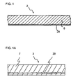
- the present invention contemplates the formation of fiber-reinforced gypsum panel having a homogeneous structure throughout, as illustrated by board 2 in FIG. 1 and board 3 in FIG. 1A .
- reinforcing mesh 29 is embedded in the back surface of the gypsum/fiber matrix 6 of the board as shown in FIG. 1 . If desired the mesh 29 may be spaced in a controlled manner between the front and back surfaces of the gypsum/fiber matrix 7 of the board as shown in FIG. 1A .
- One particularly suitable application of the composite gypsum/wood-fiber material discussed above is for the production of the composite wallboard 2, 3.
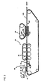
- a process for making the composite wallboard is illustrated schematically in FIG. 2 .
- the process begins with a mixing of uncalcined gypsum 10, host particles (typically cellulosic fibers, e.g., wood fibers) 14 and water 12 in a mixer 16 to form a dilute aqueous feed slurry 18.
- the source of the gypsum 10 may be raw ore or the by-product of a flue-gas-desulphurization or other calcium sulfate generating processes.
- the gypsum 10 may be of a relatively high purity, i.e., preferably at least about 92-96%, and finely ground, for example, to 92-96% minus 100 mesh or smaller. Larger particles may lengthen the conversion time.
- the gypsum 10 can be introduced to the reactor feed mixer 16 either as a dry powder or via an aqueous slurry.
- host particle is meant to cover any macroscopic particle, such as a fiber, a chip or a flake, of a substance other than gypsum.
- the particle which is generally insoluble in the slurry liquid, should also have accessible voids therein; whether pits, cracks, fissures, hollow cores, or other surface imperfections, which are penetrable by the slurry menstruum and within which calcium sulfate crystals can form. It is also desirable that such voids are present over an appreciable portion of the particle; it being apparent that the more and better distributed the voids, the greater and more geometrically stable will be the physical bonding between the gypsum and host particle.
- the substance of the host particle should have desirable properties lacking in the gypsum, and, preferably, at least higher tensile and flexural strength.
- a lignocellulosic fiber, particularly a wood fiber is an example of a host particle especially well suited for the composite material and process of the invention.
- the host particle is a paper fiber.
- wood or cellulose fiber(s) are often used hereafter for convenience in place of the broader term.
- the source of the cellulosic fiber 14 may be waste paper, wood pulp, wood flakes, and/or another plant fiber or synthetic source. It is preferable that the fiber be one that is porous, hollow, split and/or rough surfaced such that its physical geometry provides accessible interstices or voids which accommodate the penetration of dissolved calcium sulfate. In any event the source, for example, wood pulp, may also require prior processing to break up clumps, separate oversized and undersized material, and, in some cases, pre-extract strength retarding materials and/or contaminants that could adversely affect the calcination of the gypsum; such as hemicelluloses, acetic acid, etc.
- the ground gypsum-containing solids and cellulosic (e.g., wood) fibers are mixed together to form a mixture having about 0.5 to 30% by weight cellulosic fibers, preferably 5 to 15 weight % cellulosic fibers or 10 to 15 weight % cellulosic fibers.
- the gypsum-containing solids and wood fibers are mixed in respective weight proportions of about 85 to 15.
- Sufficient water is added to make the feed slurry 18 have at most about 30% or 40% by weight solids (at least about 60% or 70% by weight liquid).
- sufficient water is added to make the feed slurry 18 have about 5-30% by weight solids (70-95 % by weight liquid) or more preferably 10-15% by weight solids (85-90 % by weight liquid).
- the feed slurry 18 is fed into a reactor system 20.
- a typical reactor system 20 includes a pressure vessel equipped with a continuous stirring or mixing device. Crystal modifiers 22 can be added to the slurry at this point, if desired, to modify crystallization or to lower the calcining temperature.
- Slurry is continuously pumped into the reactor 20 with the direct injection of steam to bring the slurry temperature of the vessel to between about 240 °F (116 °C) and about 310 °F (154 °C), and autogeneous pressure.
- the lower temperature being approximately the practical minimum at which the calcium sulfate dihydrate will calcine to the hemihydrate state (typically calcium sulfate alpha hemihydrate) within a reasonable time.
- the higher temperature being about the maximum temperature for calcining hemihydrate without undue risk of decomposition of the lignocellulosic components.
- the slurry temperature is preferably about 285 °F (140 °C) to 305 °F (152 °C).
- the slurry 18 is preferably continuously mixed or stirred to maintain suspension of fibers and to keep fresh solute in contact with the growing crystals as the conversion is taking place.
- the calcium sulfate dihydrate will convert to the hemihydrate molecule.
- the dihydrate goes into solution and the hemihydrate form precipitates and recrystallizes to a well formed crystal differing from the original starting hemihydrate.
- the solution aided by the continuous agitation to keep the particles in suspension, will wet out and penetrate the open voids in the host fibers. As saturation of the solution is reached, the hemihydrate will nucleate and begin forming crystals in, on and around the voids and along the walls of the host fibers.
- the dissolved calcium sulfate penetrates into the voids in the wood fibers and subsequently precipitates as acicular hemihydrate crystals within, on and about the voids and surfaces of the wood-fibers.
- Optional process modifying or property enhancing additives such as accelerators, retarders, weight reducing fillers, etc. may be added to the product slurry, typically after it is discharged from the reactor 20 and before it is dewatered.
- the product slurry 23 then feeds a headbox 26.
- the slurry from the reactor 20 feeds a slurry holding tank (not shown) prior to feeding the headbox 26.
- the slurry discharges from the headbox 26 as a full width slurry stream 28 which feeds onto a continuous felting/dewatering conveyor 44 having flat porous forming fabric ( Fig. 3 ), such as the type used in paper making operations (for example, a fourdrinier forming wire).
- the headbox 26 feeds slurry stream 28 into a forming pond 45 on the conveyor 44.
- the headbox 26 generally comprises a housing 25 and two horizontal, counter rotating, perforated distribution rolls 26A, 26B that extend substantially across the width of the conveyor 44.
- the distribution rolls 26A, 26B rotate in opposite directions as shown by arrows in FIG. 4 .
- the housing 25 of the headbox 26 includes a first curved section 26E shaped to match the curvature of the cylindrical surface of the first horizontal, perforated distribution roll 26A.
- the housing 25 also includes a second curved section 26F shaped to match the curvature of the cylindrical surface of the second horizontal, perforated distribution roll 26B.
- the two curved sections 26E, 26F extend across the width of the headbox 26.
- a weir 26C is formed by the intersection of the curved sections 26E, 26F, and separates first horizontal, perforated distribution roll 26A from second horizontal, perforated distribution roll 26B.
- a sluice 26D is provided at the downstream end of the second curved section 26F. Sluice 26D extends vertically downwards from second curved section 26F and extends across the width of the conveyor 44.
- the second curved section 26F is closer to the conveyor 44 than the first curved section 26E.
- the headbox 26 has an upstream leading edge underneath the portion of the second curved section 26F closest to the conveyor 44 and has a downstream lip 25A underneath sluice 26D.
- the upstream lip of the headbox 26 is the portion 25B of the second curved section 26F closest to the conveyor 44 and is spaced from the downstream lip 25A by a distance "L1".
- a downstream portion of the headbox 26 extends from portion 25B to the end of the headbox 26.
- the slurry 28 exits the headbox 26 by running over the sluice 26D and into the forming pond 45.
- the headbox 26 uniformly disperses the calcined slurry 28, having at least about 70% liquid by weight, across the width of the forming table or conveyor 44 ( FIG. 3 ), where vacuum boxes 32 are used to dewater the slurry into a mat of generally 28-41% moisture content (wet basis) (40-70% moisture content on a dry basis) to perform mat forming/dewatering step 60 ( FIG. 2 ).
- a layer of mesh 29, e.g., fiberglass scrim unrolls from a feed roll 31 and passes onto an infeeding sheet (or plate) 47, under the headbox 26 and over a rod 38 ( FiGs. 4 and 6 ) into the forming pond 45.
- the direction of travel "T" of the mesh 29 is shown as an arrow in FIG 4 .
- the rod 38 ( FIGs. 4 and 6 ) is attached to the infeeding sheet (or plate) 47.
- the layer of mesh 29, fed over the infeeding sheet (or plate) 47 under the headbox 26, is held at an elevation downstream of the headbox 26 by the rod 38 and infeeding sheet 47.
- the rod 38 and sheet (or plate) 47 are made of metal (for example steel or aluminum), polymer or a durable composite.
- FIG. 4 shows an enlarged view of a portion of the production line of FIG. 3 showing the metal infeeding sheet 47 extending under the headbox 26 and around the rod 38.
- Process flow is from left to right for both the forming wire (conveyor 44) and the scrim (mesh) 29 which is fed over the sheet 47 under the headbox 26 and exits as the slurry is falling from the headbox 26 onto the area where the downstream end of the sheet 47 with rod 38 is located.
- the rod 38 and infeeding sheet (or plate) 47 are submerged in the slurry 28 of the forming pond 45. This quickly embeds the mesh 29 to minimize disruption of formation of a mat panel.
- the downstream end of the infeeding sheet 47 includes the rod 38 and is located below, slightly upstream of, or slightly downstream of, headbox downstream lip 25A.
- the downstream end of the sheet 47 containing the rod 38 could be in a range of 0 to 4 inches (or other suitable distance) upstream or downstream of the headbox downstream lip 25A.
- the presence of the sheet 47 assists in preventing slurry backflow under the header when the downstream end of the sheet 47 Is downstream of the lip 25A.
- the downstream end of the sheet 47 may be moved upstream to below the downstream half (distance "L1") of the second curved section 26F.
- the sheet 47 has an inverted S-shaped bend.
- the lowest elevation of the inverted S-shaped bend is where the bottom of the sheet contacts the forming wire 44 under the headbox 26.
- the highest elevation of the sheet 47 is at the infeed of the scrim upstream of the headbox.
- the downstream end of the sheet 47 has an intermediate elevation.
- the S-shaped curve of the metal sheet 47 has its lowest point about 1/8 to 1/2, typically about 1/4, of the length "L2" of the infeeding sheet 47 before the downstream end of the sheet at rod 38 ( FIG. 4 ).
- the sheet 47 typically has an upwards bend from the lowest point towards its downstream end.
- the angle of the upwards bend is somewhat dependent on the elevation of the headbox above the forming wire the tension on the fiberglass scrim web, and the line speed.
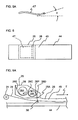
- the bend starts 15 to 45 cm (6 to 18 inches) from the downstream end of the sheet 47 and has a slope forming an angle "A" ( FIG 5A ) of at most about 20 degrees from a horizontal axis.
- Sheet 47 has two nips. One is the nip of the sheet 47 with the headbox lip 25A, or other portion of the second cylindrical section 26B, above it and the mesh 29 passing between. The second nip is the nip of the sheet 47 with the conveyor 44 underneath it and the forming wire passing between.
- the furthest upstream edge of sheet 47 should be spaced above the incoming forming fabric a distance "L3", for example 0.5 to 3 inches, to be far enough above the incoming forming fabric that no contact is made that might damage the forming fabric or catch on a fabric seam or edge seal.
- FIG. 4 shows the headbox 26 separated by a substantial distance from the conveyor 44, in actuality the nip (downstream portion) of the sheet 47, the scrim 29 and the headbox downstream lip 25A form a seal to keep a substantial amount of slurry from leaking under the headbox 26 and behind the downstream lip 25A. Slurry building up upstream of the downstream lip 25A and upstream of the sheet 47 downstream end distorts the lip 25A causing irregular formation.
- the tension on the mesh 29 allows the mesh 29 to be embedded at a controlled depth. With little tension, vacuum force applied by vacuum boxes 32 during dewatering (step 60 on FIG. 2 ) moves the mesh 29 to the bottom of the forming pond 45 and of the resulting board. Vacuum is applied to vacuum boxes 32 from a vacuum generating device such as a vacuum pump, most preferably a liquid ring pump.
- a vacuum generating device such as a vacuum pump, most preferably a liquid ring pump.
- FIG. 5 shows a perspective view of the rod 38 having a longitudinal axis "L" and the infeeding sheet 47. As seen in FIG. 5 one end of the sheet 47 is attached to the rod 38 by being wrapped around the rod 38. However, the rod 38 and sheet 47 could be attached in other ways or be a single integral piece if desired.
- FIG. 6 shows a schematic top view of the upstream end of the conveyor 44 and shows the forming pond 45, the rod 38 and the infeeding sheet 47, the sheet 47 extends under the headbox 26 and is upstream of the rod 38. Process flow is from left to right.
- FIG. 6A shows an arrangement not part of the invention in which the infeeding sheet is replaced by an elevating rod 38 at or about the downstream end of a headbox 26.
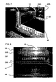
- FIG. 7 is a photograph of an arrangement not part of the invention showing the downstream side of the headbox 26, a portion of the conveyor 44, and the rod 38 just downstream of the headbox without the infeeding sheet.
- FIG. 8 is a photograph of the embodiment employing an infeeding sheet and rod (not shown).
- FIG. 8 shows the upstream bottom side of the headbox 26, a portion of the conveyor 44, and the upstream end of the infeeding sheet 47 mounted to extend upstream of the headbox lip upstream 25B to define an inlet side for feeding scrim under the headbox 26.
- the upstream half of the S curve of the infeeding sheet 47 is missing, Thus, one can see how the forming wire seam and/or edge seal might catch if the upstream half of the S curve of the infeeding sheet 47 is not provided.
- the bottom of the upstream part of the infeeding sheet 47 is in contact with the top of the forming wire of the conveyor 44 under the headbox 26.
- the infeeding sheet is the lighter colored member resting on the black forming wire of the conveyor 44.
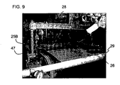
- FIG. 9 is a photograph showing feeding the scrim 29 between the infeeding sheet 47 and the back lip of the headbox 26.
- the very edge of the infeeding sheet 47 is seen sticking out from the left side underneath the scrim 29 and at an elevation above the forming wire to prevent snagging.
- the scrim 29 keeps the infeeding sheet 47 clean in the forming pond 45 and does not adversely affect formation.
- the top side of the scrim 29 is in contact with the bottom of the headbox upstream lip 25B during startup and the bottom of the scrim 29 is in contact with the infeeding sheet 47 upper surface.
- flow is from right to left. Some slurry 28 has leaked under the upstream lip 25B due to the hydraulic head of the forming pond 45 and typically forms a seal against further leakage.
- FIG. 10 shows a first view of a forming pond 45 filled with slurry.
- FIG. 11 shows a enlarged view of a portion of the forming pond 45 filled with slurry without disruption of the slurry due to the sheet/rod device.
- the downstream end (wet line) of the forming pond 45 is where the darker colored pond becomes lighter colored. It is lighter colored because the water has been stripped from the surface of the pond.
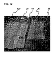
- FIG. 12 is a photograph showing an example of a piece of rod 38, infeeding sheet 47, and fiberglass mesh scrim 29 attached to a piece of cardboard 49 at one end and formed into a piece of panel at the other end.
- the cardboard 49 taped to the scrim 29 facilitates initially feeding the scrim 29 when the conveyor is started.
- the vertical force of the cardboard 49 on the forming wire of the conveyor 44 due to the vacuum from vacuum boxes 32 keeps the scrim 29 moving at the same speed as the forming wire until the forming wire is covered with slurry.
- the vacuum then applies its vertical force to the forming wire covered with slurry to maintain the same line speed between the mesh and the wire.
- the wet (primary) press 34 As shown in FIG. 3 of the forming line apparatus 30, downstream of the vacuum boxes 32, the wet (primary) press 34, which has alternating nips of suction and plain rolls, and a porous fabric, further dewaters and consolidates the mat under the combined effect of vacuum and pressure to a moisture content (wet basis) of 23-35% (30-55% on a dry basis) to produce a mat 120.
- the wet (primary) press 34 1) removes about 80-90% of remaining water; and 2) decreases slurry volume by the water removal to nip the filter cake mat to a desired thickness.
- a water recycle stream 80 FIG. 2
- An example of a hydration curve is shown in US Patent No 6,197,235 . Only slight hydration (less than 10%) occurs in the primary press 34.
- the secondary press 36 1) imparts a surface texture or smoothness that is the negative image of the surface of the belt used, 2) achieves a final calibrated board thickness as the setting composite expands against the press belt or die, and 3) aids in improving flexural strength as the crystallizing composite expands during rehydration against the press belt, thereby densifying the panel surfaces.
- This secondary press 36 decreases thickness variation through a fixed-gap nip setting slightly less than the desired end result board thickness and slightly greater than the closest gap in the primary press 34.
- the gypsum expansion against such a fixed-gap surface also improves ultimate bending strength.
- Expansion of the crystal formation with the fibrous particles gripped therein forces the setting mat against the belt 49 of the secondary press 36 as the rehydration rate increases to reach a relative temperature level, being a certain percentage of the difference between the starting rehydration temperature and the highest temperature achieved during rehydration, at which point the mat exits the press 48.
- hydration may take from only a few minutes to an hour or more. Because of the interlocking of the acicular hemihydrate crystals with the wood-fibers, and the removal of most of the carrier liquid from the filter cake, migration of the calcium sulfate particles is averted, leaving a homogeneous composite. The rehydration produces a recrystallization of the hemihydrate to dihydrate in place within and about the voids and on and about the wood fibers, thereby preserving the homogeneity of the composite. The crystal growth also connects the calcium sulfate crystals on adjacent fibers to form an overall crystalline matrix, enhanced in strength by the reinforcement of the wood fibers.
- the unique composite material When finally set, the unique composite material exhibits desired properties contributed by both of its two major components.
- the wood fibers increase the ductile strength, particularly flexural strength, of the gypsum matrix, while the gypsum acts as a coating and stiffening binder to protect the wood fiber and impart fire resistant.
- a particular surface texture can be imparted to the filter cake in the wet pressing operation to provide a board with a textured finish as taught by US Patent No. 6,197,235 .
- a surface laminate or coating could be applied after the wet pressing step and/or after the final drying, which removes excess water to achieve a stable strong finished panel. Drying to remove excess water removes at least some of the free water. After drying, the board still contains the water chemically bound to the gypsum and may still contain some free water. If desired, the products may have a surface coating applied, some before and some after the drying step. At any rate, many additional variations of this aspect of the process will occur readily to those skilled in the art. After the dewatered filter cake is pressed, rehydrated and dried, the resulting board typically has a density between 40-70 pcf.
- the mat 120 is dried in a drier 68 and then sent to trimming and cutting device 66 to form boards of the desired lengths and widths. If desired, trimming and cutting may occur before and/or after drying. Also, if desired, cut excess pieces of board can be recycled via stream 82 through a scrim removal step to the mixer 16. If edge chipping of the edge trim occurs, the scrim removal step is minimized.
- a fiber-reinforced board is produced that allows the panels to pass the ASTM E119 test procedure.
- 6.2 kg (13.6 lb.) of wood fiber (generated from Spruce wood chips using a Bauer 415 rotating double disc refiner) was mixed with 55.6 kg (122.4 lb.) of gypsum in 350 kg (171 lb) of water to form a slurry.
- the slurry was calcined at 295 °F (146 °C) for 15 minutes with a continuous reactor system.
- Resulting hemihydrate slurry was fed continuously to a headbox concurrently with continuous fiberglass scrim fed under the headbox over a piece of sheet metal in an S shape with the downstream edge of the sheet metal tightly bound around a 3/8 inch diameter (0.95 cm) length of threaded rod that was mounted at its ends in the side deckles downstream of a 26 inch (66cm) wide headbox.
- Slurry was dewatered with table vacuum at 10" Hg (24.4 cm Hg) vacuum prior to entering a primary press with vacuum rolls set at daylight gap settings of 0.440 inches (1.12 cm).
- Primary press vacuum was as high as 18 inches Hg (46 cm Hg).
- a continuous forming wire under the headbox and slurry and primary press transported the mat into a continuous press with a solid rubber-faced top belt, maintained at a daylight gap opening of 0.480 inches (1.22 cm).
- Mat entering the secondary press was soft to thumb pressure and hard to thumb pressure at the press exit, indicating the progression of hydration from the hemihydrate to the dihydrate gypsum form.
- Continuous mat was cut to 8 feet (2.44 m) long panels with a high pressure water jet.
Landscapes
- Engineering & Computer Science (AREA)
- Manufacturing & Machinery (AREA)
- Chemical & Material Sciences (AREA)
- Ceramic Engineering (AREA)
- Mechanical Engineering (AREA)
- Producing Shaped Articles From Materials (AREA)
- Press-Shaping Or Shaping Using Conveyers (AREA)
- Paper (AREA)
- Manufacturing Of Tubular Articles Or Embedded Moulded Articles (AREA)
- Air Bags (AREA)
Abstract
Description
- The present invention relates generally to a method and device for making a paperless gypsum/fiber board with improved Impact resistance More particularly, the present invention relates to a method and device, according to the preamble of
claim 12, for making a gypsum/fiber board having a reinforcing mesh embedded in the board. - Conventional gypsum wallboard or panel is typically manufactured from a plaster slurry wherein a wet slurry of calcium sulfate hemihydrate, generally referred to as calcined gypsum, is placed between two layers of paper and the slurry is allowed to set The set gypsum is a hard and rigid product obtained when the calcined gypsum reacts with water to form calcium sulfate dihydrate. Gypsum is calcium sulfate in the stable dihydrate state, CaSO4.2H2O, and includes the naturally occurring mineral, the synthetically derived mineral, and the dihydrate material formed by the hydration of calcined gypsum. Calcined gypsum is either calcium sulfate hemihydrate (CaSO4·½ H2O) or calcium sulfate anhydrite (CaSO4). When calcium sulfate dihydrate is heated sufficiently, in a process called calcining, the water of hydration is driven off and there can be formed either calcium sulfate hemihydrate or calcium sulfate anhydrite, depending on the temperature and duration of exposure. When the dihydrate is heated sufficiently in a saturated steam environment, the dihydrate dissolves and the hemihydrate form precipitates out of solution as well formed crystals. When water is added to the calcined gypsum to cause the gypsum to set, in essence, the calcined gypsum reacts with water, and the gypsum is reformed.
- Paper covered wallboard is a popular building material. However, for certain building applications it would be advantageous to provide a gypsum panel that did not rely on paper surface sheets for strength and other properties. Several prior art fiber-reinforced gypsum panels are as follows:
-
U.S. Patent No. 5,320,677 describes a composite product and a process for producing the product in which a dilute slurry of gypsum particles and cellulosic fibers is heated under pressure to convert the gypsum to calcium sulfate alpha hemihydrate. The cellulosic fibers have pores or voids on the surface and the alpha hemihydrate crystals form within, on and around the voids and pores of the cellulosic fibers. The heated slurry is then dewatered to form a mat, preferably using equipment similar to paper making equipment, and before the slurry cools enough to rehydrate the hemihydrate to gypsum, the mat is pressed into a board of the desired configuration. The pressed mat is cooled and the hemihydrate rehydrates to gypsum to form a dimensionally stable, strong and useful building board. -
U.S. Patent No. 6,197,235 discloses a method for texturing gypsum fiber panels and producing surface textured panels, edge tapers, and deeper patterned wainscot-type panels, involving the use of a flexible die with a textured surface. The die is pressed onto the panel in its slurry state just after the onset of an exothermic rehydration reaction. Partial hydration and setting occur during pressing by the die to form a textured mat. The mat is removed from contact with the die at a point along the rehydration temperature curve about at or less than one-half of the rise to the greatest rehydration temperature. -
U.S. Patent No. 6, 605, 186 discloses a headbox for use in a water felting process for gypsum/fiber board production including a housing and two rotating horizontal distribution rolls. The housing has curved sections shaped to respectively conform to the outer cylindrical surface of the distribution rolls. Each curved section is respectively closely spaced to a portion of the outer cylindrical surface of both distribution rolls. - Scrim embedment in panel products has been used to improve physical properties.
U.S. Patent No. 6, 508, 895 discloses a gypsum/fiber board having improved impact resistance produced by mixing predetermined amounts of fibers, calcined gypsum and water to form a mixture; and embedding a reinforcing mesh in a layer of the mixture over the upper surface of a forming belt; and forming a board composed of bonded fibers and gypsum with the mesh embedded in the surface of the board. - Previous attempts have used scrim embedment downstream of a headbox Scrim fed downstream of the headbox limits control of embedding, caused buildup problems on scrim embedment equipment and adversely affected formation properties in the forming pond. In this process, the scrim is fed above the headbox, down into the pond and then under a rod which assists in placing the scrim at a desired depth.
- It is an object of the present invention to provide a method and device for making a mesh and fiber-reinforced paperless gypsum board.
- It is another object of present invention to provide a paperless gypsum/fiber board having a mesh embedded in the backside to provide improved impact resistance as determined by Soft Body Impact Resistance according to ASTM E695 and by Hard Body Impact Resistance according to USG method as documented in independent reports HPWLI #7122 and HPWLI #7811-02. Copies of information in these third party independent testing reports may be requested through USG Corporation, Chicago IL.
- The term "paperless" gypsum/fiber board, as used herein, is intended to distinguish the fiber reinforced gypsum panels to which the present invention relates from conventional prior art gypsum panels, which are referred to as "wall board" or "dry wall" which have at least one surface comprised of paper, including "wall board" or "dry wall" having some form of fiber-reinforcement in the core.
- According to the present invention, a method of producing a gypsum/fiber board is provided as defined in
claim 1. An apparatus for producing such a board is provided as defined inclaim 12. - A mixture is formed of gypsum and host particles together with water to form a slurry mixture. (Alternatively, if desired this method could be performed with beta calcium sulfate or blends of alpha calcium sulfate and beta calcium sulfate.) The mixture and a reinforcing mesh are fed into a panel forming area over the upper surface of a porous forming fabric or "wire" similar to that used in fourdrinier wet felting to form a panel mat. In particular, the mesh is fed under the headbox and into the forming pond as the calcined slurry mixture passes from the headbox into the forming pond. Forming fabric is typically an endless belt woven of plastics or metal. Typical plastics include polyester, or nylon, etc. Typical metals include metallic material such as brass, bronze or steel. Forming wire is a subset of forming fabric and is typically made of metallic material.
- While traveling to the forming pond, the mesh passes over a transverse member, which extends transverse (perpendicular) to the direction of travel of the mesh, and is located over a portion of the forming fabric. A downstream portion of the transverse member is under a downstream portion of the headbox or downstream of the headbox. The reinforcing mesh passes over the transverse member and into the forming pond to embed the reinforcing mesh in the slurry mixture in the forming pond. Afterwards, water is removed from the slurry mixture to form a panel mat with the mesh embedded in the panel mat. When the panel mat having the embedded mesh is pressed, the calcined gypsum of the pressed panel mat rehydrates to form a board comprising bonded host particles and gypsum with the mesh embedded In the board; and the board is dried to provide a finished board with the mesh embedded in the finished board.
- The transverse member is an infeeding sheet. If desired, the sheet may have at its downstream end an elongate member which has a longitudinal axis transverse (perpendicular) to the direction of travel of the mesh. The infeeding sheet is preferably attached to the elongate member and extends upstream of the elongate member undermeath the headbox.
- Preferably the sheet has a transverse bend starting from a location upstream of the downstream end of the sheet or upstream of the headbox such that a smooth bend of the sheet terminates at the transverse rod and at the elevation of the top of the transverse rod, allowing the scrim (mesh) to maintain continuous contact with the sheet surface and provide a desired self-cleaning effect The sheet transverse bend preferably forms an upwards bend towards its downstream end. The angle of the upwards bend is somewhat dependent on the elevation of the headbox above-the terming wire, the tension on the fiberglass scrim web, and the line speed. Preferably, the transverse bend starts 15 to 46 cm (6 to 18 inches) from the downstream end of the sheet and has a slope forming an angle of at most about 20 degrees with a horizontal axis. At the other end, or infeed end of the sheet, the sheet smoothly bends up from the elevation of the infeeding forming wire (forming fabric) to allow smooth transfer of the scrim to the sheet without snagging either the scrim or the forming wire.
- Thus, the mesh, e.g., scrim, is fed under a headbox and over a transverse member held at an elevation underneath a downstream portion of the headbox or downstream of the headbox. This embeds the mesh to minimize disruption of formation. The tension on the mesh then allows the mesh to be embedded at a controlled depth in the forming pond downstream of the transverse member. With little tension, vacuum force moves the mesh to the bottom of the forming pond and the bottom of the resulting board. The slurry and mesh are fed onto a continuously moving dewatering fabric (wire) and the force of the vacuum pulling water through the dewatering forming fabric maintains the vertical force on the mat and scrim on the forming fabric which is in turn pulled in the horizontal direction down the forming line
- Preferably, the sheet has an inverted S-curve. The lowest elevation of the inverted S-curve is typically where the bottom of the sheet contacts the forming wire under the headbox. The highest elevation of the inverted S-curve is typically at the infeed of the scrim upstream of the headbox. The downstream end of the inverted S-curve has an intermediate elevation.
- Preferably, the transverse member extends across the width of the forming wire in the forming area. The elongate member and sheet serve to space the mesh about 0.32 to 1.3 cm (0.125 to 0.5 inches) above the forming wire surface after the mesh passes under a headbox or slurry delivery device. The spacing of the mesh above the forming wire allows a portion of the fiber/gypsum mixture to be between the mesh and forming wire, and embed the mesh, in the finished board.
- With more tension, the mesh may be embedded further away from the bottom of the panel. The bend in the sheet metal causes the device to be self-cleaning.
- The resulting panel mat with the mesh embedded in the panel mat is then pressed for further water removal and mat consolidation. The calcined gypsum of the panel mat is then rehydrated with residual mat moisture to form a board comprising bonded host particles and gypsum with the mesh embedded in the board. Then the board is dried to provide a finished board with the mesh embedded in the board. The process allows a substantial density range of from 320 to 1120 kg/m3, which combined with the large possible thickness range of about 6 to 31 mm, gives a variety of potential product sizes.
- Embedding a reinforcing mesh in the gypsum/fiber board, in accordance with the present invention, provides many advantages including high production rates, better product aesthetics, integral consolidation of reinforcing mesh in board, and reduced product cost Embedding a reinforcing mesh also improves the handling properties of the board. The scrim (also known as mesh) is fully embedded into the board: a scrim merely on the surface is easily damaged and tom loose.
- The product of the present invention can include a flush mesh which does not mark up the face of the adjacent panel on which it is stacked, and improved retention of the reinforcement in the panels as it is protected from wearing and rubbing on the surface. Another product benefit is the tensioning of the mesh in the product to provide enhanced stiffness to the panel.
- These and other advantages of the invention will be apparent to those skilled in the art following the more detailed discussion of the embodiments which follows with reference to the accompanying drawings, which form part of this specification.
- The accompanying drawings, which are incorporated in and constitute a part of the specification, illustrate several embodiments of the invention and together with the description, serve to explain the operation of the present invention.
-
FIG. 1 is a sectional end view of a homogeneous, one-layer board made according to an embodiment of the present invention. -
FIG. 1A is a sectional end view of another homogeneous, one-layer board made according to an embodiment of the present invention. -
FIG. 2 is a schematic block flow diagram of a process for forming a composite material according to an embodiment of the present invention. -
FIG. 3 is a schematic side view illustrating a production line, employing an embodiment for forming gypsum fiberboard having a head box, dewatering vacuum, a dewatering primary press, and infeed assembly for feeding mesh into slurry, arranged for processing a rehydratable gypsum fiber slurry upon a conveyor. -
FIG. 4 shows an enlarged side view of a portion of the production line ofFIG. 3 showing the infeeding sheet extends under the headbox and around the longitudinal element, e.g., rod, wherein process flow is from left to right for both the forming wire and the scrim (mesh) which is fed over the sheet under the headbox and exits as the slurry is falling from the headbox onto the area where the longitudinal element, e.g. rod is located. -
FIG. 5 shows a perspective view of the longitudinal element, e.g., rod having a longitudinal axis "L" and the infeeding sheet attached to the rod. -
FIG. 5A shows a side view of the infeeding sheet attached to the rod. -
FIG. 6 shows a schematic top view of the upstream end of the forming pond which includes the rod and sheet, the sheet extends under the headbox and is upstream of the rod. -
FIG. 6A shows an arrangement not part of the invention in which an infeeding sheet is replaced by a rod downstream of a headbox. -
FIG. 7 is a photograph of an arrangement not part of the invention showing the downstream side of the headbox, a portion of the conveyor, and the rod just downstream of the headbox without the infeeding sheet to more fully show the rod. -
FIG. 8 is a photograph of the embodiment ofFIG 7 showing the upstream side of the headbox, a portion of the conveyor, and the upstream end of the sheet metal mounted to extend upstream of the mesh inlet side of the headbox to define an inlet side for feeding scrim under the headbox and an inlet opening between the sheet metal and the headbox lip. -
FIG. 9 is a photograph showing feeding the scrim between the infeeding sheet and a lip of the headbox. In this photograph process flow is from right to left. As the scrim feeds under the headbox, the scrim keeps the sheet metal clean in the forming pond. -
FIG. 10 shows a first view of a forming pond (slurry pond) filled with slurry. -
FIG. 11 shows an enlarged view of a portion of the forming pond filled with slurry and that the scrim and sheet metal/rod assembly does not adversely affect formation. -
FIG. 12 is a photograph showing an example of a piece of rod, sheet metal, and fiberglass mesh scrim attached to a piece of cardboard at one end and formed into a piece of composite panel at the other end. The cardboard taped to the scrim assists to initially feed the scrim when the machine is started. - The present invention relates generally to a paperless gypsum/fiber board with improved impact resistance, and to a process for making such a gypsum/fiber board. The paperless gypsum/fiber board having improved impact resistance is produced by embedding a reinforcing mesh, preferably a flexible fiberglass mesh, in the backside of a gypsum fiber board. In the process, the mesh is fed into the forming area of the panel before the panel is pressed and dried.
- Enhanced and improved impact resistance of the gypsum/fiber board is provided by embedding a reinforcing mesh in the backside of the gypsum/fiber board. The mesh may be either woven or non-woven and may be made of a variety of materials, for example, fiberglass, polyester, or polypropylene. Preferably the mesh is made from a flat yam of a low elasticity material such as fiberglass mesh. Most preferably the mesh is a fiber glass mesh having openings in the mesh of sufficient size to allow a quantity of the gypsum/fiber slurry to pass through the mesh and embed the mesh in set gypsum in the final product
- The following meshes are typical meshes which are usable with the present invention. Also, meshes having from 2 per 2.5 cm (inch) to roughly 10 per 2.5 cm (inch) opening are usable with the present invention.
- One useful woven fiberglass mesh is available from Bayex under the number 0040/286. BAYEX 0040/286 is a Leno weave mesh having a warp and weft of 6 per 2.5 cm (inch) (ASTM D-3775), a weight of 152 g/m2 (4.5 ounces per square yard) (ASTMD-3776), a thickness of 0.4 mm (0.016 inches) (ASTMD D-1777) and a minimum tensile of 26 and 35 N/cm (150 and 200 pounds per inch) in the warp and weft, respectively (ASTM D-5035). It is alkali resistant and has a firm hand. Other fiberglass meshes having approximately the same dimensions have opening of sufficient size to allow a portion of the gypsum/fiber mix to pass through the mesh during formation of the board and may be used.
- Another useful woven fiberglass mesh is available from Bayex under the number 0038/503. BAYEX 0038/503 is a Leno weave mesh having a warp of 6 per 2.5 cm (inch) and weft of 5 per 2.5 cm (inch) (ASTM D-3775), a weight of 142 g/m2 (4.2 ounces per square yard) (ASTM D-3776), a thickness of 0.4 mm (0.016 inches) (ASTM D-1777) and a minimum tensile of 26 and 29 N/cm (150 and 165 pounds per inch) in the warp and weft, respectively (ASTM D-5035). It is alkali resistant and has a firm hand.
- Yet another useful woven fiberglass mesh is available from BAYEX under the number 0038/504. BAYEX 0038/504 is a Leno weave mesh having a warp of 6 per 2.5 cm (inch) and weft of 5 per 2.5 cm (inch) (ASTMD D-3775), a weight of 142 g/m2 (4.2 ounces per square yard) (ASTMD-3776), a thickness of 0.4 mm (0.016 inches) (ASTM D-1777) and a minimum tensile of 26 and 29 N/cm (150 and 165 pounds per inch) in the warp and weft, respectively (ASTM D-5035). It is alkali resistant and has a firm hand. Other fiberglass meshes having approximately the same dimensions have opening of sufficient size to allow a portion of the gypsum/fiber slurry to pass through the mesh during formation of the board and may be used.
- Yet another useful woven fiberglass mesh is available from BAYEX under the number 4447/252. BAYEX 4447/252 is a Leno weave mesh having a warp of 2.6 per 2.5 cm (inch) and weft of 2.6 per 2.5 cm (inch) (ASTM D-3775), a weight of 156 g/m2 (4.6 ounces per square yard) (ASTM D-3776), a thickness of 0.66 mm (0.026 inches) (ASTM D-1777) and a minimum tensile of 26 and 30 N/cm (150 and 174 pounds per inch) the warp and weft, respectively (ASTM D-5035). It is alkali resistant and has a firm hand. Other fiberglass meshes having approximately the same dimensions have opening of sufficient size to allow a portion of the gypsum/fiber mix to pass through the mesh during formation of the board and may be used.
- The mesh is preferably embedded in the backside of the board with the warp oriented in the longitudinal direction of the board. Because the board of the present invention may expand multi-directionally during the setting step, the use of a mesh which is extensible may provide better bonding to the gypsum/fiber board. During the first pressing step, the compression and consolidation should match the rate of water removal and volume decrease caused by the vacuum pressing to produce the proper pore area in the panel. In the second pressing step after the mat springback after the first pressing, the pore space should be removed without disrupting the formation laid down in the forming step. In either case the forming step is important and any later disruption by pressing and mat dislocation will lower the strength and quality of the finished panel.
- It is preferred to have the mesh substantially embedded in the board and covered by the gypsum/fiber mix, because this secures the mesh to the board. Additionally, completely embedding the mesh in the gypsum/fiber mix provides the best impact resistance to the board. Completely embedding the mesh in the gypsum/fiber mix also makes the reinforcement less perceptible to the consumer and improves overall surface properties.
- If desired, coatings can be used on the scrim to improve wettability, bonding, etc. such as polyvinyl alcohol and polyvinyl acetate related compounds as well as other wetting agents commonly known to those skilled in the art.
- The materials used to produce the gypsum fiber board are conventional materials. The term "gypsum", as used herein, means calcium sulfate in the stable dihydrate state; i.e. CaSO4·2H20, and includes the naturally occurring mineral, the synthetically derived equivalents, such as FGD gypsum (a synthetic gypsum which is the by-product of flue gas desulphurization), and the dihydrate material formed by the hydration of calcium sulfate hemihydrate (stucco) or anhydrite. The term "calcium sulfate material", as used herein, means calcium sulfate in any of its forms, namely calcium sulfate anhydrite, calcium sulfate hemihydrate, calcium sulfate dihydrate and mixtures thereof.
- The host particles are typically organic fibers that serve to reinforce the gypsum, and are preferably lignocellulosic fibers that are readily available. For example the cellulosic fiber may be recycled waste products such as box board or cardboard trim, waste paper, used newspaper, and reject fibers of pulp production.
- Additional components of the type conventionally used in gypsum fiberboard may be used in the board of the present invention. Such conventional components include accelerators, water resistance agents, fungicides and the like.
- The present invention contemplates the formation of fiber-reinforced gypsum panel having a homogeneous structure throughout, as illustrated by
board 2 inFIG. 1 andboard 3 inFIG. 1A . - In
board 2 having a homogeneous structure, reinforcingmesh 29 is embedded in the back surface of the gypsum/fiber matrix 6 of the board as shown inFIG. 1 . If desired themesh 29 may be spaced in a controlled manner between the front and back surfaces of the gypsum/fiber matrix 7 of the board as shown inFIG. 1A . - One particularly suitable application of the composite gypsum/wood-fiber material discussed above is for the production of the
composite wallboard FIG. 2 . - The process begins with a mixing of
uncalcined gypsum 10, host particles (typically cellulosic fibers, e.g., wood fibers) 14 andwater 12 in amixer 16 to form a diluteaqueous feed slurry 18. The source of thegypsum 10 may be raw ore or the by-product of a flue-gas-desulphurization or other calcium sulfate generating processes. Thegypsum 10 may be of a relatively high purity, i.e., preferably at least about 92-96%, and finely ground, for example, to 92-96% minus 100 mesh or smaller. Larger particles may lengthen the conversion time. Thegypsum 10 can be introduced to thereactor feed mixer 16 either as a dry powder or via an aqueous slurry. - The term "host particle" is meant to cover any macroscopic particle, such as a fiber, a chip or a flake, of a substance other than gypsum. The particle, which is generally insoluble in the slurry liquid, should also have accessible voids therein; whether pits, cracks, fissures, hollow cores, or other surface imperfections, which are penetrable by the slurry menstruum and within which calcium sulfate crystals can form. It is also desirable that such voids are present over an appreciable portion of the particle; it being apparent that the more and better distributed the voids, the greater and more geometrically stable will be the physical bonding between the gypsum and host particle. The substance of the host particle should have desirable properties lacking in the gypsum, and, preferably, at least higher tensile and flexural strength. A lignocellulosic fiber, particularly a wood fiber, is an example of a host particle especially well suited for the composite material and process of the invention. According to a preferred embodiment of the invention, the host particle is a paper fiber. However, without intending to limit the material and/or particles that qualify as a "host particle", wood or cellulose fiber(s) are often used hereafter for convenience in place of the broader term.
- The source of the
cellulosic fiber 14 may be waste paper, wood pulp, wood flakes, and/or another plant fiber or synthetic source. It is preferable that the fiber be one that is porous, hollow, split and/or rough surfaced such that its physical geometry provides accessible interstices or voids which accommodate the penetration of dissolved calcium sulfate. In any event the source, for example, wood pulp, may also require prior processing to break up clumps, separate oversized and undersized material, and, in some cases, pre-extract strength retarding materials and/or contaminants that could adversely affect the calcination of the gypsum; such as hemicelluloses, acetic acid, etc. - The ground gypsum-containing solids and cellulosic (e.g., wood) fibers are mixed together to form a mixture having about 0.5 to 30% by weight cellulosic fibers, preferably 5 to 15 weight % cellulosic fibers or 10 to 15 weight % cellulosic fibers. For example, the gypsum-containing solids and wood fibers are mixed in respective weight proportions of about 85 to 15.
- Sufficient water is added to make the
feed slurry 18 have at most about 30% or 40% by weight solids (at least about 60% or 70% by weight liquid). For example, sufficient water is added to make thefeed slurry 18 have about 5-30% by weight solids (70-95 % by weight liquid) or more preferably 10-15% by weight solids (85-90 % by weight liquid). - The
feed slurry 18 is fed into areactor system 20. Atypical reactor system 20 includes a pressure vessel equipped with a continuous stirring or mixing device.Crystal modifiers 22 can be added to the slurry at this point, if desired, to modify crystallization or to lower the calcining temperature. Slurry is continuously pumped into thereactor 20 with the direct injection of steam to bring the slurry temperature of the vessel to between about 240 °F (116 °C) and about 310 °F (154 °C), and autogeneous pressure. The lower temperature being approximately the practical minimum at which the calcium sulfate dihydrate will calcine to the hemihydrate state (typically calcium sulfate alpha hemihydrate) within a reasonable time. The higher temperature being about the maximum temperature for calcining hemihydrate without undue risk of decomposition of the lignocellulosic components. The slurry temperature is preferably about 285 °F (140 °C) to 305 °F (152 °C). - In the
reactor 20, theslurry 18 is preferably continuously mixed or stirred to maintain suspension of fibers and to keep fresh solute in contact with the growing crystals as the conversion is taking place. - When the
slurry 18 is processed under these conditions for a sufficient period of time, for example about 15 minutes, the calcium sulfate dihydrate will convert to the hemihydrate molecule. (The dihydrate goes into solution and the hemihydrate form precipitates and recrystallizes to a well formed crystal differing from the original starting hemihydrate.) The solution, aided by the continuous agitation to keep the particles in suspension, will wet out and penetrate the open voids in the host fibers. As saturation of the solution is reached, the hemihydrate will nucleate and begin forming crystals in, on and around the voids and along the walls of the host fibers. - In the
reactor 20, it is believed the dissolved calcium sulfate penetrates into the voids in the wood fibers and subsequently precipitates as acicular hemihydrate crystals within, on and about the voids and surfaces of the wood-fibers. Optional process modifying or property enhancing additives (not shown), such as accelerators, retarders, weight reducing fillers, etc. may be added to the product slurry, typically after it is discharged from thereactor 20 and before it is dewatered. - The continuous stream 23 of alpha hemihydrate calcium sulfate and host fibers exits the
reactor system 20. The product slurry 23 then feeds aheadbox 26. Optionally, the slurry from thereactor 20 feeds a slurry holding tank (not shown) prior to feeding theheadbox 26. The slurry discharges from theheadbox 26 as a fullwidth slurry stream 28 which feeds onto a continuous felting/dewatering conveyor 44 having flat porous forming fabric (Fig. 3 ), such as the type used in paper making operations (for example, a fourdrinier forming wire). In particular, theheadbox 26 feedsslurry stream 28 into a formingpond 45 on theconveyor 44. - The
headbox 26 generally comprises ahousing 25 and two horizontal, counter rotating, perforated distribution rolls 26A, 26B that extend substantially across the width of theconveyor 44. The distribution rolls 26A, 26B rotate in opposite directions as shown by arrows inFIG. 4 . Thehousing 25 of theheadbox 26 includes a firstcurved section 26E shaped to match the curvature of the cylindrical surface of the first horizontal,perforated distribution roll 26A. Thehousing 25 also includes a secondcurved section 26F shaped to match the curvature of the cylindrical surface of the second horizontal,perforated distribution roll 26B. The twocurved sections headbox 26. - A
weir 26C is formed by the intersection of thecurved sections perforated distribution roll 26A from second horizontal,perforated distribution roll 26B. Asluice 26D is provided at the downstream end of the secondcurved section 26F.Sluice 26D extends vertically downwards from secondcurved section 26F and extends across the width of theconveyor 44. - The second
curved section 26F is closer to theconveyor 44 than the firstcurved section 26E. Theheadbox 26 has an upstream leading edge underneath the portion of the secondcurved section 26F closest to theconveyor 44 and has adownstream lip 25A underneathsluice 26D. The upstream lip of theheadbox 26 is theportion 25B of the secondcurved section 26F closest to theconveyor 44 and is spaced from thedownstream lip 25A by a distance "L1". A downstream portion of theheadbox 26 extends fromportion 25B to the end of theheadbox 26. - A description of a
typical headbox 26 is provided byUS patent no. 6,605,186 to Miller. - The
slurry 28 exits theheadbox 26 by running over thesluice 26D and into the formingpond 45. Theheadbox 26 uniformly disperses thecalcined slurry 28, having at least about 70% liquid by weight, across the width of the forming table or conveyor 44 (FIG. 3 ), wherevacuum boxes 32 are used to dewater the slurry into a mat of generally 28-41% moisture content (wet basis) (40-70% moisture content on a dry basis) to perform mat forming/dewatering step 60 (FIG. 2 ). - Also, as part of the mat forming/
dewatering step 60, as theheadbox 26 feedsslurry 28 to the formingpond 45 on theconveyor 44, a layer ofmesh 29, e.g., fiberglass scrim, unrolls from afeed roll 31 and passes onto an infeeding sheet (or plate) 47, under theheadbox 26 and over a rod 38 (FiGs. 4 and6 ) into the formingpond 45. The direction of travel "T" of themesh 29 is shown as an arrow inFIG 4 . The rod 38 (FIGs. 4 and6 ) is attached to the infeeding sheet (or plate) 47. - The layer of
mesh 29, fed over the infeeding sheet (or plate) 47 under theheadbox 26, is held at an elevation downstream of theheadbox 26 by therod 38 andinfeeding sheet 47. Typically, therod 38 and sheet (or plate) 47 are made of metal (for example steel or aluminum), polymer or a durable composite. -
FIG. 4 shows an enlarged view of a portion of the production line ofFIG. 3 showing themetal infeeding sheet 47 extending under theheadbox 26 and around therod 38. Process flow is from left to right for both the forming wire (conveyor 44) and the scrim (mesh) 29 which is fed over thesheet 47 under theheadbox 26 and exits as the slurry is falling from theheadbox 26 onto the area where the downstream end of thesheet 47 withrod 38 is located. - As seen in
FIG. 4 , therod 38 and infeeding sheet (or plate) 47 are submerged in theslurry 28 of the formingpond 45. This quickly embeds themesh 29 to minimize disruption of formation of a mat panel. - The downstream end of the
infeeding sheet 47 includes therod 38 and is located below, slightly upstream of, or slightly downstream of, headboxdownstream lip 25A. For example, the downstream end of thesheet 47 containing therod 38 could be in a range of 0 to 4 inches (or other suitable distance) upstream or downstream of the headboxdownstream lip 25A. The presence of thesheet 47 assists in preventing slurry backflow under the header when the downstream end of thesheet 47 Is downstream of thelip 25A. If desired, the downstream end of thesheet 47 may be moved upstream to below the downstream half (distance "L1") of the secondcurved section 26F. - Typically, the
sheet 47 has an inverted S-shaped bend. The lowest elevation of the inverted S-shaped bend is where the bottom of the sheet contacts the formingwire 44 under theheadbox 26. The highest elevation of thesheet 47 is at the infeed of the scrim upstream of the headbox. The downstream end of thesheet 47 has an intermediate elevation. Typically, the S-shaped curve of themetal sheet 47, has its lowest point about 1/8 to 1/2, typically about 1/4, of the length "L2" of theinfeeding sheet 47 before the downstream end of the sheet at rod 38 (FIG. 4 ). - The
sheet 47 typically has an upwards bend from the lowest point towards its downstream end. The angle of the upwards bend is somewhat dependent on the elevation of the headbox above the forming wire the tension on the fiberglass scrim web, and the line speed. Typically, the bend starts 15 to 45 cm (6 to 18 inches) from the downstream end of thesheet 47 and has a slope forming an angle "A" (FIG 5A ) of at most about 20 degrees from a horizontal axis. -
Sheet 47 has two nips. One is the nip of thesheet 47 with theheadbox lip 25A, or other portion of the secondcylindrical section 26B, above it and themesh 29 passing between. The second nip is the nip of thesheet 47 with theconveyor 44 underneath it and the forming wire passing between. The furthest upstream edge ofsheet 47 should be spaced above the incoming forming fabric a distance "L3", for example 0.5 to 3 inches, to be far enough above the incoming forming fabric that no contact is made that might damage the forming fabric or catch on a fabric seam or edge seal. - Although
FIG. 4 shows theheadbox 26 separated by a substantial distance from theconveyor 44, in actuality the nip (downstream portion) of thesheet 47, thescrim 29 and the headboxdownstream lip 25A form a seal to keep a substantial amount of slurry from leaking under theheadbox 26 and behind thedownstream lip 25A. Slurry building up upstream of thedownstream lip 25A and upstream of thesheet 47 downstream end distorts thelip 25A causing irregular formation. - Without the sheet 47 (for example see
FIG. 6A ), if therod 38 is close enough to the upstream side of thelip 25A and close enough to the moving forming fabric underneath it, satisfactory board may be made if tolerances and control of equipment can be maintained. - The tension on the
mesh 29 allows themesh 29 to be embedded at a controlled depth. With little tension, vacuum force applied byvacuum boxes 32 during dewatering (step 60 onFIG. 2 ) moves themesh 29 to the bottom of the formingpond 45 and of the resulting board. Vacuum is applied tovacuum boxes 32 from a vacuum generating device such as a vacuum pump, most preferably a liquid ring pump. - With more tension on the
mesh 29, themesh 29 is embedded further away from the bottom of the mat 46 which eventually forms thepanel 120. The bend in the sheet orplate 47 causes the device to be self-cleaning and eliminates the problems associated with use of therod 38 alone. -
FIG. 5 shows a perspective view of therod 38 having a longitudinal axis "L" and theinfeeding sheet 47. As seen inFIG. 5 one end of thesheet 47 is attached to therod 38 by being wrapped around therod 38. However, therod 38 andsheet 47 could be attached in other ways or be a single integral piece if desired. -
FIG. 6 shows a schematic top view of the upstream end of theconveyor 44 and shows the formingpond 45, therod 38 and theinfeeding sheet 47, thesheet 47 extends under theheadbox 26 and is upstream of therod 38. Process flow is from left to right. -
FIG. 6A shows an arrangement not part of the invention in which the infeeding sheet is replaced by an elevatingrod 38 at or about the downstream end of aheadbox 26. -
FIG. 7 is a photograph of an arrangement not part of the invention showing the downstream side of theheadbox 26, a portion of theconveyor 44, and therod 38 just downstream of the headbox without the infeeding sheet. -
FIG. 8 is a photograph of the embodiment employing an infeeding sheet and rod (not shown).FIG. 8 shows the upstream bottom side of theheadbox 26, a portion of theconveyor 44, and the upstream end of theinfeeding sheet 47 mounted to extend upstream of the headbox lip upstream 25B to define an inlet side for feeding scrim under theheadbox 26. In this photograph, the upstream half of the S curve of theinfeeding sheet 47 is missing, Thus, one can see how the forming wire seam and/or edge seal might catch if the upstream half of the S curve of theinfeeding sheet 47 is not provided. - The bottom of the upstream part of the
infeeding sheet 47 is in contact with the top of the forming wire of theconveyor 44 under theheadbox 26. The infeeding sheet is the lighter colored member resting on the black forming wire of theconveyor 44. -
FIG. 9 is a photograph showing feeding thescrim 29 between theinfeeding sheet 47 and the back lip of theheadbox 26. The very edge of theinfeeding sheet 47 is seen sticking out from the left side underneath thescrim 29 and at an elevation above the forming wire to prevent snagging. As thescrim 29 feeds under theheadbox 26, thescrim 29 keeps theinfeeding sheet 47 clean in the formingpond 45 and does not adversely affect formation. The top side of thescrim 29 is in contact with the bottom of the headboxupstream lip 25B during startup and the bottom of thescrim 29 is in contact with theinfeeding sheet 47 upper surface. In this photograph process flow is from right to left. Someslurry 28 has leaked under theupstream lip 25B due to the hydraulic head of the formingpond 45 and typically forms a seal against further leakage. -
FIG. 10 shows a first view of a formingpond 45 filled with slurry. -
FIG. 11 shows a enlarged view of a portion of the formingpond 45 filled with slurry without disruption of the slurry due to the sheet/rod device. - In both
FiGs. 10 and 11 , the downstream end (wet line) of the formingpond 45 is where the darker colored pond becomes lighter colored. It is lighter colored because the water has been stripped from the surface of the pond. -
FIG. 12 is a photograph showing an example of a piece ofrod 38,infeeding sheet 47, andfiberglass mesh scrim 29 attached to a piece ofcardboard 49 at one end and formed into a piece of panel at the other end. Thecardboard 49 taped to thescrim 29 facilitates initially feeding thescrim 29 when the conveyor is started. The vertical force of thecardboard 49 on the forming wire of theconveyor 44 due to the vacuum fromvacuum boxes 32 keeps thescrim 29 moving at the same speed as the forming wire until the forming wire is covered with slurry. The vacuum then applies its vertical force to the forming wire covered with slurry to maintain the same line speed between the mesh and the wire. - As shown in
FIG. 3 of the forming line apparatus 30, downstream of thevacuum boxes 32, the wet (primary)press 34, which has alternating nips of suction and plain rolls, and a porous fabric, further dewaters and consolidates the mat under the combined effect of vacuum and pressure to a moisture content (wet basis) of 23-35% (30-55% on a dry basis) to produce amat 120. The wet (primary) press 34: 1) removes about 80-90% of remaining water; and 2) decreases slurry volume by the water removal to nip the filter cake mat to a desired thickness. If desired, a water recycle stream 80 (FIG. 2 ) may be provided to recycle water removed by either thevacuum boxes 32 and/or the wet (primary)press 34 to thefeed water 12. The spacing between the first presses 34 and secondary presses 36 -whether measured by time or distance--is related to the hydration the calcium sulfate hemihydrate. An example of a hydration curve is shown inUS Patent No 6,197,235 . Only slight hydration (less than 10%) occurs in theprimary press 34. - After the
primary press 34 the mat feeds asecondary press 36 used for medium to higher density products. Thesecondary press 36 1) imparts a surface texture or smoothness that is the negative image of the surface of the belt used, 2) achieves a final calibrated board thickness as the setting composite expands against the press belt or die, and 3) aids in improving flexural strength as the crystallizing composite expands during rehydration against the press belt, thereby densifying the panel surfaces. - This
secondary press 36 decreases thickness variation through a fixed-gap nip setting slightly less than the desired end result board thickness and slightly greater than the closest gap in theprimary press 34. The gypsum expansion against such a fixed-gap surface also improves ultimate bending strength. - The majority of the rehydration of the alpha hemihydrate to the dihydrate occurs in the
secondary press 36. - Expansion of the crystal formation with the fibrous particles gripped therein forces the setting mat against the
belt 49 of thesecondary press 36 as the rehydration rate increases to reach a relative temperature level, being a certain percentage of the difference between the starting rehydration temperature and the highest temperature achieved during rehydration, at which point the mat exits thepress 48. - Depending on the accelerators, retarders, crystal modifiers, or other additives provided in the slurry, hydration may take from only a few minutes to an hour or more. Because of the interlocking of the acicular hemihydrate crystals with the wood-fibers, and the removal of most of the carrier liquid from the filter cake, migration of the calcium sulfate particles is averted, leaving a homogeneous composite. The rehydration produces a recrystallization of the hemihydrate to dihydrate in place within and about the voids and on and about the wood fibers, thereby preserving the homogeneity of the composite. The crystal growth also connects the calcium sulfate crystals on adjacent fibers to form an overall crystalline matrix, enhanced in strength by the reinforcement of the wood fibers.
- When finally set, the unique composite material exhibits desired properties contributed by both of its two major components. The wood fibers increase the ductile strength, particularly flexural strength, of the gypsum matrix, while the gypsum acts as a coating and stiffening binder to protect the wood fiber and impart fire resistant.
- Also, if desired, a particular surface texture can be imparted to the filter cake in the wet pressing operation to provide a board with a textured finish as taught by
US Patent No. 6,197,235 . A surface laminate or coating could be applied after the wet pressing step and/or after the final drying, which removes excess water to achieve a stable strong finished panel. Drying to remove excess water removes at least some of the free water. After drying, the board still contains the water chemically bound to the gypsum and may still contain some free water. If desired, the products may have a surface coating applied, some before and some after the drying step. At any rate, many additional variations of this aspect of the process will occur readily to those skilled in the art. After the dewatered filter cake is pressed, rehydrated and dried, the resulting board typically has a density between 40-70 pcf. - After discharging from
secondary press 36 themat 120 is dried in a drier 68 and then sent to trimming and cuttingdevice 66 to form boards of the desired lengths and widths. If desired, trimming and cutting may occur before and/or after drying. Also, if desired, cut excess pieces of board can be recycled viastream 82 through a scrim removal step to themixer 16. If edge chipping of the edge trim occurs, the scrim removal step is minimized. - In a preferred embodiment, a fiber-reinforced board is produced that allows the panels to pass the ASTM E119 test procedure.
- In an example of the present invention, 6.2 kg (13.6 lb.) of wood fiber (generated from Spruce wood chips using a Bauer 415 rotating double disc refiner) was mixed with 55.6 kg (122.4 lb.) of gypsum in 350 kg (171 lb) of water to form a slurry. The slurry was calcined at 295 °F (146 °C) for 15 minutes with a continuous reactor system. Resulting hemihydrate slurry was fed continuously to a headbox concurrently with continuous fiberglass scrim fed under the headbox over a piece of sheet metal in an S shape with the downstream edge of the sheet metal tightly bound around a 3/8 inch diameter (0.95 cm) length of threaded rod that was mounted at its ends in the side deckles downstream of a 26 inch (66cm) wide headbox.
- Slurry was dewatered with table vacuum at 10" Hg (24.4 cm Hg) vacuum prior to entering a primary press with vacuum rolls set at daylight gap settings of 0.440 inches (1.12 cm). Primary press vacuum was as high as 18 inches Hg (46 cm Hg). A continuous forming wire under the headbox and slurry and primary press transported the mat into a continuous press with a solid rubber-faced top belt, maintained at a daylight gap opening of 0.480 inches (1.22 cm). Mat entering the secondary press was soft to thumb pressure and hard to thumb pressure at the press exit, indicating the progression of hydration from the hemihydrate to the dihydrate gypsum form. Continuous mat was cut to 8 feet (2.44 m) long panels with a high pressure water jet.
- After further hydration, panels were dried into strong final boards with the fiberglass scrim embedded approximately 1/16 inch (0.16 cm) from the bottom of the back surface of the resulting half inch (1.27 cm) thick panels. Panels could be easily handled from the ends and flexed without catastrophic failure, demonstrating improved handleability due to the fiberglass scrim.
- The forms of invention shown and described herein are to be considered only as illustrative. It will be apparent to those skilled in the art that numerous modifications may be made therein without departing from the scope of the appended claims.
Claims (13)
- A method of producing a gypsum/fiber board (2) comprising the steps of:mixing ground gypsum (10) and host particles (14) of a fibrous reinforcing material and sufficient liquid comprising water to make a slurry (18) having at least 60% liquid by weight;calcining the gypsum (10) in the presence of the host particles (14) and the water, by heating the slurry under pressure, to form a slurry mixture (23) comprising water and calcium sulfate alpha hemihydrate crystals;feeding the slurry mixture (23) through a headbox (26) to a panel forming area over the upper surface of a flat porous forming fabric of a moving conveyor (44);providing a transverse member (47) over a portion of the forming fabric, wherein a downstream portion of the transverse member is under a downstream portion of the headbox (26) or downstream of the headbox (26);passing a layer of reinforcing mesh (29) under the headbox (26), over the transverse member, and into a forming pond (45) on the forming fabric to embed the reinforcing mesh (29 in the slurry mixture (23) in the forming pond (45),
wherein the transverse member (47) extends transverse to a direction of movement of the mesh (29);wherein the transverse member comprises a sheet (47) located over a portion of the forming fabric, the sheet (47) having an upstream portion, a downstream portion and a middle portion between the upstream portion and downstream portion, wherein the upstream portion is upstream of an upstream lip of the headbox (26), the middle portion is under the headbox (26), and the reinforcing mesh (29) passes between the sheet (47) and the headbox (26) and into the forming pond (45) to embed the reinforcing mesh (29) in the slurry mixture (23) in the forming pond (45);removing water from the slurry mixture (23) to form a panel mat (120) with the mesh (29) embedded in the panel mat (120);pressing the panel mat (120) having the embedded mesh (29);rehydrating the calcined gypsum (10) of the pressed panel mat (120) to form a board comprising bonded host particles (14) and gypsum (10) with the mesh (29) embedded in the board (2); anddrying the board (2) to provide a finished board (2) with the mesh (29) embedded in the finished board (2). - The method of claim 1, wherein the transverse member (47) further comprising an elongate member (38) attached to the downstream portion of the sheet (47), wherein the elongate member (38) has a longitudinal axis transverse to the direction of travel of the mesh (29).
- The method of any one of the claims 1 or 2, wherein the mesh (29) is embedded in a lower surface of the panel mat (120).
- The method of any one of the claims 1 to 3, wherein the mesh (29) is spaced above a forming belt (49) in the panel forming area.
- The method of any one of the claims 1 to 4, wherein the downstream end of the sheet (47) forms a bend having an upwards angle of at most about 20 degrees relative to a horizontal plane upon which the middle portion lies.
- The method of any one of the claims 1 to 5,
wherein the host particles (14) have voids on their surfaces and/or within their bodies penetrable by the slurry menstruum containing suspended and/or dissolved gypsum (10), the slurry being sufficiently dilute to substantially wet out the penetrable voids in the host particles (14) and to foster the formation of acicular calcium sulfate alpha hemihydrate crystals when heated under pressure;
wherein the slurry (18) is heated in a pressure vessel, with continuous agitation, to a temperature sufficient to calcine the gypsum (10) to calcium sulfate alpha-hemihydrate, and the slurry is maintained at such temperature until at least some calcium sulfate hemihydrate has substantially crystallized in and about the voids in the host particles (14). - The method of any one of the claims 1 to 6, wherein the sheet (47) has an inverted S-shaped bend with the lowest elevation where a bottom of the sheet (47) contacts the forming fabric under the headbox (26) and the highest elevation of the sheet (47) at the infeed of the mesh (29) upstream of the headbox (26) and an intermediate elevation at the downstream end of the sheet (47).
- The method of any one of the claims 1 to 7, wherein the pressing is complete when the panel mat (120) is from about 40 to 70 % fully rehydrated.
- The method of any one of the claims 1 to 8, wherein the host particles are cellulosic particles (14) selected from the group consisting of fibers, chips and flakes.
- The method of any one of the claims 1 to 8, wherein the host particles (14) comprise wood fibers and the solids content in the slurry mixture (23) is about 0.5 to 30% by weight of said wood fibers, in particular about 5-15% by weight of said wood fibers.
- The method of any one of the claims 1 to 10, wherein the mesh (29) is fully embedded in the finished board, so as not to mark up the face of a second board on which the finished board is stacked
- An apparatus for producing a gypsum/fiber board (2) comprising:a mixer (16) for mixing ground gypsum (10) and host particles (14) of a fibrous reinforcing material and sufficient liquid comprising water to make a slurry (18) having at least 60% liquid by weight;a reactor (20) for calcining the gypsum (10) in the presence of the host particles (14) and the water, by heating the slurry under pressure, to form a slurry mixture (23) comprising water and acicular calcium sulfate alpha hemihydrate crystals;a headbox (26) for feeding the slurry mixture (23) through the headbox (26) into a forming pond (45) of a panel forming area over the upper surface of a flat porous forming fabric on a conveyor (44);vacuum means (32) for removing water from the slurry mixture (23) to form a panel mat (120) with the mesh (29) embedded in the panel mat (120);a first press (34) for pressing the panel mat (120) having the embedded mesh (29);a second press (36) for permitting rehydrating of the calcined gypsum (10) of the pressed panel mat (120) to form a board (2) comprising bonded host particles (14) and gypsum (10) with the mesh (29) embedded in the board (2); anda drier (68) for drying the board (2) to remove free water and provide a finished board (2) with the mesh (29) embedded in the finished board (2);characterised in that the apparatus further comprisesa transverse member (47) over a portion of the forming fabric, wherein a downstream portion of the transverse member (47) is under a downstream portion of the headbox (26) or downstream of the headbox (26);a space between the headbox (26) and the transverse member (47) for feeding a reinforcing mesh (29) between the transverse member and the head box (26) and then into the forming pond (45) to embed the reinforcing mesh (29) in the slurry mixture (23) in the forming pond (45);wherein the transverse member comprises a sheet (47) located over a portion of the forming fabric, the sheet (47) having an upstream portion, a downstream portion and a middle portion between the upstream portion and downstream portion, wherein the upstream portion is upstream of an upstream lip of the head box (26), the middle portion is under the headbox (26), and the sheet (47) is spaced from the headbox (26) to form the space for passing therethrough the reinforcing mesh (29).
- The apparatus of claim 12, wherein the downstream end of the sheet (47) forms a bend having an upwards angle of at most about 20 degrees relative to a horizontal plane upon which the middle portion lies.
Applications Claiming Priority (2)
| Application Number | Priority Date | Filing Date | Title |
|---|---|---|---|
| US11/533,886 US7897079B2 (en) | 2006-09-21 | 2006-09-21 | Method and apparatus for scrim embedment into wet processed panels |
| PCT/US2007/018979 WO2008036166A2 (en) | 2006-09-21 | 2007-08-29 | Method and apparatus for scrim embedment into wet processed panels |
Publications (3)
| Publication Number | Publication Date |
|---|---|
| EP2064037A2 EP2064037A2 (en) | 2009-06-03 |
| EP2064037A4 EP2064037A4 (en) | 2009-11-25 |
| EP2064037B1 true EP2064037B1 (en) | 2011-10-12 |
Family
ID=39201614
Family Applications (1)
| Application Number | Title | Priority Date | Filing Date |
|---|---|---|---|
| EP07837467A Not-in-force EP2064037B1 (en) | 2006-09-21 | 2007-08-29 | Method and apparatus for embedding a reinforcing mesh into wet processed panels |
Country Status (13)
| Country | Link |
|---|---|
| US (1) | US7897079B2 (en) |
| EP (1) | EP2064037B1 (en) |
| JP (1) | JP5340942B2 (en) |
| CN (1) | CN101535017B (en) |
| AT (1) | ATE528115T1 (en) |
| AU (1) | AU2007297821B2 (en) |
| CA (1) | CA2663320C (en) |
| CR (1) | CR10721A (en) |
| MX (1) | MX2009002883A (en) |
| NZ (1) | NZ575436A (en) |
| RU (1) | RU2443550C2 (en) |
| TW (1) | TWI387530B (en) |
| WO (1) | WO2008036166A2 (en) |
Families Citing this family (10)
| Publication number | Priority date | Publication date | Assignee | Title |
|---|---|---|---|---|
| EP2163532A1 (en) * | 2008-09-11 | 2010-03-17 | Claudius Peters Technologies GmbH | Method and device for manufacturing stone plaster |
| JP2010121058A (en) * | 2008-11-20 | 2010-06-03 | Nichiha Corp | Environmentally-friendly wet process type hard fiberboard |
| AU2010246330A1 (en) * | 2010-11-01 | 2012-05-17 | Finish Systems International, Llc | Stone-wood composite base engineered flooring |
| CN102490248A (en) * | 2011-11-15 | 2012-06-13 | 赤壁人和建材有限公司 | Fiber gypsum board production process and equipment |
| US8801902B1 (en) * | 2013-09-18 | 2014-08-12 | Usg Interiors, Llc | Water reduction by modulating vacuum |
| US11224990B2 (en) | 2016-08-05 | 2022-01-18 | United States Gypsum Company | Continuous methods of making fiber reinforced concrete panels |
| US10272399B2 (en) | 2016-08-05 | 2019-04-30 | United States Gypsum Company | Method for producing fiber reinforced cementitious slurry using a multi-stage continuous mixer |
| US10981294B2 (en) | 2016-08-05 | 2021-04-20 | United States Gypsum Company | Headbox and forming station for fiber-reinforced cementitious panel production |
| US11173629B2 (en) | 2016-08-05 | 2021-11-16 | United States Gypsum Company | Continuous mixer and method of mixing reinforcing fibers with cementitious materials |
| MX2021014667A (en) | 2019-06-07 | 2022-01-11 | Georgia Pacific Gypsum Llc | Building panels, assemblies, and associated methods. |
Family Cites Families (38)
| Publication number | Priority date | Publication date | Assignee | Title |
|---|---|---|---|---|
| US2200155A (en) | 1936-11-21 | 1940-05-07 | United States Gypsum Co | Manufacture of wallboard having a cementitious core |
| GB772581A (en) | 1954-06-23 | 1957-04-17 | Saint Gobain | Reinforced plaster panels and process for their manufacture |
| GB771581A (en) | 1955-04-20 | 1957-04-03 | Lobitos Oilfields Ltd | Improvements in or relating to the production of oil-soluble petroleum sulphonic acids |
| GB1536663A (en) | 1975-10-28 | 1978-12-20 | Cape Boards & Panels Ltd | Fibre-reinforced articles |
| US4334786A (en) | 1978-02-08 | 1982-06-15 | Saint Gobain Industries | Process and mechanism for evolutive pulp flow regulation |
| FR2416777A1 (en) * | 1978-02-08 | 1979-09-07 | Saint Gobain | MANUFACTURING OF PLASTER PLATES |
| IE49483B1 (en) | 1979-05-30 | 1985-10-16 | Bpb Industries Ltd | Production of building board |
| FR2484899A1 (en) | 1980-06-18 | 1981-12-24 | Saint Gobain Isover | METHOD AND DEVICE FOR REMOVING WATER EXCEEDING A MIXTURE OF PLASTER AND WATER, AND PRODUCTS OBTAINED |
| JPS6113530Y2 (en) * | 1981-04-15 | 1986-04-26 | ||
| US4450022A (en) | 1982-06-01 | 1984-05-22 | United States Gypsum Company | Method and apparatus for making reinforced cement board |
| FR2547533B1 (en) | 1983-06-17 | 1986-03-21 | Montana Jacqueline | PREFABRICATED PLASTER-BASED ELEMENT, PARTICULARLY FOR THE BUILDING, AND MANUFACTURING METHOD THEREOF |
| US4647496A (en) | 1984-02-27 | 1987-03-03 | Georgia-Pacific Corporation | Use of fibrous mat-faced gypsum board in exterior finishing systems for buildings |
| SU1315316A1 (en) * | 1985-05-06 | 1987-06-07 | Уральский научно-исследовательский и проектный институт строительных материалов | Method for manufacturing fibre-containing boards and conveyer line for effecting same |
| US4646498A (en) | 1985-05-28 | 1987-03-03 | National Gypsum Company | Curtain wall panel and method |
| US4646798A (en) * | 1985-07-19 | 1987-03-03 | Byung Kwon Yoo | Drinking water dispenser with cup supporting assembly |
| US5221386A (en) | 1986-02-20 | 1993-06-22 | United States Gypsum Company | Cement board having reinforced edges |
| US5122339A (en) * | 1987-08-10 | 1992-06-16 | Martin Marietta Corporation | Aluminum-lithium welding alloys |
| US4879092A (en) * | 1988-06-03 | 1989-11-07 | General Electric Company | Titanium aluminum alloys modified by chromium and niobium and method of preparation |
| HU216298B (en) * | 1988-11-18 | 1999-06-28 | United States Gypsum Co. | Compositons based on gypsum applied as building and plaster material, wallboard and process for producing the composition |
| JPH03120013A (en) | 1989-10-02 | 1991-05-22 | Kubota Corp | Manufacture of inorganic lightweight panel |
| US5632848A (en) * | 1989-10-12 | 1997-05-27 | Georgia-Pacific Corporation | Continuous processing equipment for making fiberboard |
| US5135805A (en) | 1990-07-27 | 1992-08-04 | Georgia-Pacific Corporation | Method of manufacturing a water-resistant gypsum composition |
| US5342566A (en) | 1990-08-23 | 1994-08-30 | Carl Schenck Ag | Method of manufacturing fiber gypsum board |
| WO1992013645A1 (en) * | 1991-02-01 | 1992-08-20 | Glascrete, Inc. | Method and apparatus for production of reinforced cementitious panels |
| US5350554A (en) | 1991-02-01 | 1994-09-27 | Glascrete, Inc. | Method for production of reinforced cementitious panels |
| DE4127932A1 (en) * | 1991-08-23 | 1993-02-25 | Bold Joerg | Fibre-reinforced plasterboard mfr. - using by=product gypsum and waste paper |
| US5477652A (en) | 1993-12-07 | 1995-12-26 | General Electric Company | Composite security wall systems |
| US5504614A (en) * | 1995-01-31 | 1996-04-02 | Texas Instruments Incorporated | Method for fabricating a DMD spatial light modulator with a hardened hinge |
| JP3120013B2 (en) | 1995-03-20 | 2000-12-25 | 新日本製鐵株式会社 | Hot rolled billet joining method |
| GB2316693B (en) | 1996-08-29 | 2000-05-31 | Bpb Plc | Building board |
| US5933365A (en) * | 1997-06-19 | 1999-08-03 | Energy Conversion Devices, Inc. | Memory element with energy control mechanism |
| CA2211984C (en) | 1997-09-12 | 2002-11-05 | Marc-Andre Mathieu | Cementitious panel with reinforced edges |
| DE19905068B4 (en) | 1998-02-09 | 2009-04-09 | United States Gypsum Co., Chicago | Headbox for use in a device for performing a water entanglement process |
| US6508895B2 (en) | 1998-09-09 | 2003-01-21 | United States Gypsum Co | Method of producing gypsum/fiber board |
| US6197235B1 (en) * | 1999-02-09 | 2001-03-06 | United States Gypsum Company | Method of manufacture for textured surface panels and panel products made therefrom |
| NZ504254A (en) * | 1999-05-17 | 2001-12-21 | United States Gypsum Co | Method for making smooth surface gypsum fiberboard panels with dilute and calcined slurry deposited on pond, sprayed and pressed |
| US6752895B1 (en) * | 1999-05-18 | 2004-06-22 | United States Gypsum Company | Water spray for smooth surface gypsum fiberboard panels |
| US6775046B2 (en) * | 2002-11-06 | 2004-08-10 | Northrop Grumman Corporation | Thin film shape memory alloy reflector |
-
2006
- 2006-09-21 US US11/533,886 patent/US7897079B2/en not_active Expired - Fee Related
-
2007
- 2007-08-29 CA CA2663320A patent/CA2663320C/en not_active Expired - Fee Related
- 2007-08-29 MX MX2009002883A patent/MX2009002883A/en active IP Right Grant
- 2007-08-29 NZ NZ575436A patent/NZ575436A/en not_active IP Right Cessation
- 2007-08-29 WO PCT/US2007/018979 patent/WO2008036166A2/en not_active Ceased
- 2007-08-29 JP JP2009529180A patent/JP5340942B2/en not_active Expired - Fee Related
- 2007-08-29 AT AT07837467T patent/ATE528115T1/en not_active IP Right Cessation
- 2007-08-29 AU AU2007297821A patent/AU2007297821B2/en not_active Ceased
- 2007-08-29 RU RU2009111100/03A patent/RU2443550C2/en active
- 2007-08-29 CN CN2007800349542A patent/CN101535017B/en not_active Expired - Fee Related
- 2007-08-29 EP EP07837467A patent/EP2064037B1/en not_active Not-in-force
- 2007-09-20 TW TW096135150A patent/TWI387530B/en not_active IP Right Cessation
-
2009
- 2009-04-17 CR CR10721A patent/CR10721A/en not_active Application Discontinuation
Also Published As
| Publication number | Publication date |
|---|---|
| EP2064037A4 (en) | 2009-11-25 |
| WO2008036166A2 (en) | 2008-03-27 |
| MX2009002883A (en) | 2009-03-30 |
| TW200827158A (en) | 2008-07-01 |
| CN101535017A (en) | 2009-09-16 |
| RU2443550C2 (en) | 2012-02-27 |
| ATE528115T1 (en) | 2011-10-15 |
| WO2008036166A3 (en) | 2008-05-29 |
| CR10721A (en) | 2009-07-17 |
| JP5340942B2 (en) | 2013-11-13 |
| US7897079B2 (en) | 2011-03-01 |
| AU2007297821B2 (en) | 2011-09-08 |
| US20080073808A1 (en) | 2008-03-27 |
| CA2663320A1 (en) | 2008-03-27 |
| AU2007297821A1 (en) | 2008-03-27 |
| RU2009111100A (en) | 2010-10-27 |
| CA2663320C (en) | 2012-11-13 |
| CN101535017B (en) | 2011-07-27 |
| JP2010504232A (en) | 2010-02-12 |
| EP2064037A2 (en) | 2009-06-03 |
| HK1136243A1 (en) | 2010-06-25 |
| TWI387530B (en) | 2013-03-01 |
| NZ575436A (en) | 2011-10-28 |
Similar Documents
| Publication | Publication Date | Title |
|---|---|---|
| CA2663320C (en) | Method and apparatus for scrim embedment into wet processed panels | |
| EP0370703B1 (en) | Composite material and method of producing | |
| CA2280393C (en) | Gypsum/fiber board with improved impact resistance | |
| CN1914032B (en) | Improved process for production of gypsum/fiber board | |
| JP7689980B2 (en) | Method for regenerating gypsum panels containing hydrophobic materials and uses thereof | |
| WO2008085242A1 (en) | Fiber reinforced gypsum panel | |
| US5496441A (en) | Utilization of deinking by-product in building materials | |
| CN101883904A (en) | Be used to make the low fiber calcination process of plasterboard | |
| CA2141804C (en) | Continuous processing equipment for making fiberboard | |
| HK1136243B (en) | Method and apparatus for scrim embedment into wet processed panels | |
| IL94388A (en) | Composite gypsum material and its production | |
| HK1145348A (en) | Low fiber calcination process for making gypsum fiberboard | |
| KR20020094064A (en) | Gypsum/fiber board improved impact resistance | |
| MXPA99008051A (en) | Plaster board / fibers, with impact resistance | |
| CZ289914B6 (en) | Composite material based on gypsum, compressed board and process for producing the composite material and the board | |
| HK1026396A (en) | Gypsum/fiber board with improved impact resistance |
Legal Events
| Date | Code | Title | Description |
|---|---|---|---|
| PUAI | Public reference made under article 153(3) epc to a published international application that has entered the european phase |
Free format text: ORIGINAL CODE: 0009012 |
|
| 17P | Request for examination filed |
Effective date: 20090312 |
|
| AK | Designated contracting states |
Kind code of ref document: A2 Designated state(s): AT BE BG CH CY CZ DE DK EE ES FI FR GB GR HU IE IS IT LI LT LU LV MC MT NL PL PT RO SE SI SK TR |
|
| AX | Request for extension of the european patent |
Extension state: AL BA HR MK RS |
|
| A4 | Supplementary search report drawn up and despatched |
Effective date: 20091026 |
|
| DAX | Request for extension of the european patent (deleted) | ||
| 17Q | First examination report despatched |
Effective date: 20100212 |
|
| REG | Reference to a national code |
Ref country code: DE Ref legal event code: R079 Ref document number: 602007017863 Country of ref document: DE Free format text: PREVIOUS MAIN CLASS: B28B0001260000 Ipc: B28B0005020000 |
|
| GRAP | Despatch of communication of intention to grant a patent |
Free format text: ORIGINAL CODE: EPIDOSNIGR1 |
|
| RIC1 | Information provided on ipc code assigned before grant |
Ipc: B28B 23/00 20060101ALI20110317BHEP Ipc: B28B 5/02 20060101AFI20110317BHEP |
|
| RTI1 | Title (correction) |
Free format text: METHOD AND APPARATUS FOR EMBEDDING A REINFORCING MESH INTO WET PROCESSED PANELS |
|
| GRAS | Grant fee paid |
Free format text: ORIGINAL CODE: EPIDOSNIGR3 |
|
| GRAA | (expected) grant |
Free format text: ORIGINAL CODE: 0009210 |
|
| AK | Designated contracting states |
Kind code of ref document: B1 Designated state(s): AT BE BG CH CY CZ DE DK EE ES FI FR GB GR HU IE IS IT LI LT LU LV MC MT NL PL PT RO SE SI SK TR |
|
| REG | Reference to a national code |
Ref country code: GB Ref legal event code: FG4D |
|
| REG | Reference to a national code |
Ref country code: CH Ref legal event code: EP |
|
| REG | Reference to a national code |
Ref country code: IE Ref legal event code: FG4D |
|
| REG | Reference to a national code |
Ref country code: DE Ref legal event code: R096 Ref document number: 602007017863 Country of ref document: DE Effective date: 20111208 |
|
| REG | Reference to a national code |
Ref country code: NL Ref legal event code: VDEP Effective date: 20111012 |
|
| LTIE | Lt: invalidation of european patent or patent extension |
Effective date: 20111012 |
|
| REG | Reference to a national code |
Ref country code: AT Ref legal event code: MK05 Ref document number: 528115 Country of ref document: AT Kind code of ref document: T Effective date: 20111012 |
|
| PG25 | Lapsed in a contracting state [announced via postgrant information from national office to epo] |
Ref country code: LT Free format text: LAPSE BECAUSE OF FAILURE TO SUBMIT A TRANSLATION OF THE DESCRIPTION OR TO PAY THE FEE WITHIN THE PRESCRIBED TIME-LIMIT Effective date: 20111012 Ref country code: IS Free format text: LAPSE BECAUSE OF FAILURE TO SUBMIT A TRANSLATION OF THE DESCRIPTION OR TO PAY THE FEE WITHIN THE PRESCRIBED TIME-LIMIT Effective date: 20120212 Ref country code: BE Free format text: LAPSE BECAUSE OF FAILURE TO SUBMIT A TRANSLATION OF THE DESCRIPTION OR TO PAY THE FEE WITHIN THE PRESCRIBED TIME-LIMIT Effective date: 20111012 |
|
| PG25 | Lapsed in a contracting state [announced via postgrant information from national office to epo] |
Ref country code: GR Free format text: LAPSE BECAUSE OF FAILURE TO SUBMIT A TRANSLATION OF THE DESCRIPTION OR TO PAY THE FEE WITHIN THE PRESCRIBED TIME-LIMIT Effective date: 20120113 Ref country code: SI Free format text: LAPSE BECAUSE OF FAILURE TO SUBMIT A TRANSLATION OF THE DESCRIPTION OR TO PAY THE FEE WITHIN THE PRESCRIBED TIME-LIMIT Effective date: 20111012 Ref country code: LV Free format text: LAPSE BECAUSE OF FAILURE TO SUBMIT A TRANSLATION OF THE DESCRIPTION OR TO PAY THE FEE WITHIN THE PRESCRIBED TIME-LIMIT Effective date: 20111012 Ref country code: SE Free format text: LAPSE BECAUSE OF FAILURE TO SUBMIT A TRANSLATION OF THE DESCRIPTION OR TO PAY THE FEE WITHIN THE PRESCRIBED TIME-LIMIT Effective date: 20111012 Ref country code: NL Free format text: LAPSE BECAUSE OF FAILURE TO SUBMIT A TRANSLATION OF THE DESCRIPTION OR TO PAY THE FEE WITHIN THE PRESCRIBED TIME-LIMIT Effective date: 20111012 Ref country code: PT Free format text: LAPSE BECAUSE OF FAILURE TO SUBMIT A TRANSLATION OF THE DESCRIPTION OR TO PAY THE FEE WITHIN THE PRESCRIBED TIME-LIMIT Effective date: 20120213 |
|
| PG25 | Lapsed in a contracting state [announced via postgrant information from national office to epo] |
Ref country code: CY Free format text: LAPSE BECAUSE OF FAILURE TO SUBMIT A TRANSLATION OF THE DESCRIPTION OR TO PAY THE FEE WITHIN THE PRESCRIBED TIME-LIMIT Effective date: 20111012 |
|
| PG25 | Lapsed in a contracting state [announced via postgrant information from national office to epo] |
Ref country code: DK Free format text: LAPSE BECAUSE OF FAILURE TO SUBMIT A TRANSLATION OF THE DESCRIPTION OR TO PAY THE FEE WITHIN THE PRESCRIBED TIME-LIMIT Effective date: 20111012 Ref country code: EE Free format text: LAPSE BECAUSE OF FAILURE TO SUBMIT A TRANSLATION OF THE DESCRIPTION OR TO PAY THE FEE WITHIN THE PRESCRIBED TIME-LIMIT Effective date: 20111012 Ref country code: CZ Free format text: LAPSE BECAUSE OF FAILURE TO SUBMIT A TRANSLATION OF THE DESCRIPTION OR TO PAY THE FEE WITHIN THE PRESCRIBED TIME-LIMIT Effective date: 20111012 Ref country code: SK Free format text: LAPSE BECAUSE OF FAILURE TO SUBMIT A TRANSLATION OF THE DESCRIPTION OR TO PAY THE FEE WITHIN THE PRESCRIBED TIME-LIMIT Effective date: 20111012 Ref country code: BG Free format text: LAPSE BECAUSE OF FAILURE TO SUBMIT A TRANSLATION OF THE DESCRIPTION OR TO PAY THE FEE WITHIN THE PRESCRIBED TIME-LIMIT Effective date: 20120112 |
|
| PLBE | No opposition filed within time limit |
Free format text: ORIGINAL CODE: 0009261 |
|
| STAA | Information on the status of an ep patent application or granted ep patent |
Free format text: STATUS: NO OPPOSITION FILED WITHIN TIME LIMIT |
|
| PG25 | Lapsed in a contracting state [announced via postgrant information from national office to epo] |
Ref country code: RO Free format text: LAPSE BECAUSE OF FAILURE TO SUBMIT A TRANSLATION OF THE DESCRIPTION OR TO PAY THE FEE WITHIN THE PRESCRIBED TIME-LIMIT Effective date: 20111012 Ref country code: IT Free format text: LAPSE BECAUSE OF FAILURE TO SUBMIT A TRANSLATION OF THE DESCRIPTION OR TO PAY THE FEE WITHIN THE PRESCRIBED TIME-LIMIT Effective date: 20111012 Ref country code: PL Free format text: LAPSE BECAUSE OF FAILURE TO SUBMIT A TRANSLATION OF THE DESCRIPTION OR TO PAY THE FEE WITHIN THE PRESCRIBED TIME-LIMIT Effective date: 20111012 |
|
| 26N | No opposition filed |
Effective date: 20120713 |
|
| REG | Reference to a national code |
Ref country code: DE Ref legal event code: R097 Ref document number: 602007017863 Country of ref document: DE Effective date: 20120713 |
|
| PG25 | Lapsed in a contracting state [announced via postgrant information from national office to epo] |
Ref country code: AT Free format text: LAPSE BECAUSE OF FAILURE TO SUBMIT A TRANSLATION OF THE DESCRIPTION OR TO PAY THE FEE WITHIN THE PRESCRIBED TIME-LIMIT Effective date: 20111012 |
|
| REG | Reference to a national code |
Ref country code: CH Ref legal event code: PL |
|
| PG25 | Lapsed in a contracting state [announced via postgrant information from national office to epo] |
Ref country code: MC Free format text: LAPSE BECAUSE OF NON-PAYMENT OF DUE FEES Effective date: 20120831 |
|
| PG25 | Lapsed in a contracting state [announced via postgrant information from national office to epo] |
Ref country code: CH Free format text: LAPSE BECAUSE OF NON-PAYMENT OF DUE FEES Effective date: 20120831 Ref country code: ES Free format text: LAPSE BECAUSE OF FAILURE TO SUBMIT A TRANSLATION OF THE DESCRIPTION OR TO PAY THE FEE WITHIN THE PRESCRIBED TIME-LIMIT Effective date: 20120123 Ref country code: LI Free format text: LAPSE BECAUSE OF NON-PAYMENT OF DUE FEES Effective date: 20120831 |
|
| REG | Reference to a national code |
Ref country code: IE Ref legal event code: MM4A |
|
| PG25 | Lapsed in a contracting state [announced via postgrant information from national office to epo] |
Ref country code: FI Free format text: LAPSE BECAUSE OF FAILURE TO SUBMIT A TRANSLATION OF THE DESCRIPTION OR TO PAY THE FEE WITHIN THE PRESCRIBED TIME-LIMIT Effective date: 20111012 |
|
| PG25 | Lapsed in a contracting state [announced via postgrant information from national office to epo] |
Ref country code: IE Free format text: LAPSE BECAUSE OF NON-PAYMENT OF DUE FEES Effective date: 20120829 |
|
| PG25 | Lapsed in a contracting state [announced via postgrant information from national office to epo] |
Ref country code: MT Free format text: LAPSE BECAUSE OF FAILURE TO SUBMIT A TRANSLATION OF THE DESCRIPTION OR TO PAY THE FEE WITHIN THE PRESCRIBED TIME-LIMIT Effective date: 20111012 |
|
| PG25 | Lapsed in a contracting state [announced via postgrant information from national office to epo] |
Ref country code: TR Free format text: LAPSE BECAUSE OF FAILURE TO SUBMIT A TRANSLATION OF THE DESCRIPTION OR TO PAY THE FEE WITHIN THE PRESCRIBED TIME-LIMIT Effective date: 20111012 |
|
| PG25 | Lapsed in a contracting state [announced via postgrant information from national office to epo] |
Ref country code: LU Free format text: LAPSE BECAUSE OF NON-PAYMENT OF DUE FEES Effective date: 20120829 |
|
| PG25 | Lapsed in a contracting state [announced via postgrant information from national office to epo] |
Ref country code: HU Free format text: LAPSE BECAUSE OF FAILURE TO SUBMIT A TRANSLATION OF THE DESCRIPTION OR TO PAY THE FEE WITHIN THE PRESCRIBED TIME-LIMIT Effective date: 20070829 |
|
| REG | Reference to a national code |
Ref country code: FR Ref legal event code: PLFP Year of fee payment: 10 |
|
| REG | Reference to a national code |
Ref country code: FR Ref legal event code: PLFP Year of fee payment: 11 |
|
| REG | Reference to a national code |
Ref country code: FR Ref legal event code: PLFP Year of fee payment: 12 |
|
| PGFP | Annual fee paid to national office [announced via postgrant information from national office to epo] |
Ref country code: FR Payment date: 20190826 Year of fee payment: 13 Ref country code: DE Payment date: 20190828 Year of fee payment: 13 |
|
| PGFP | Annual fee paid to national office [announced via postgrant information from national office to epo] |
Ref country code: GB Payment date: 20190827 Year of fee payment: 13 |
|
| REG | Reference to a national code |
Ref country code: DE Ref legal event code: R119 Ref document number: 602007017863 Country of ref document: DE |
|
| GBPC | Gb: european patent ceased through non-payment of renewal fee |
Effective date: 20200829 |
|
| PG25 | Lapsed in a contracting state [announced via postgrant information from national office to epo] |
Ref country code: DE Free format text: LAPSE BECAUSE OF NON-PAYMENT OF DUE FEES Effective date: 20210302 Ref country code: FR Free format text: LAPSE BECAUSE OF NON-PAYMENT OF DUE FEES Effective date: 20200831 |
|
| PG25 | Lapsed in a contracting state [announced via postgrant information from national office to epo] |
Ref country code: GB Free format text: LAPSE BECAUSE OF NON-PAYMENT OF DUE FEES Effective date: 20200829 |