EP2063791B1 - Cerebral vasculature device - Google Patents
Cerebral vasculature device Download PDFInfo
- Publication number
- EP2063791B1 EP2063791B1 EP07811013.7A EP07811013A EP2063791B1 EP 2063791 B1 EP2063791 B1 EP 2063791B1 EP 07811013 A EP07811013 A EP 07811013A EP 2063791 B1 EP2063791 B1 EP 2063791B1
- Authority
- EP
- European Patent Office
- Prior art keywords
- braided structure
- distal
- expandable
- polymer
- proximal
- Prior art date
- Legal status (The legal status is an assumption and is not a legal conclusion. Google has not performed a legal analysis and makes no representation as to the accuracy of the status listed.)
- Active
Links
- 230000002490 cerebral effect Effects 0.000 title claims description 19
- 210000005166 vasculature Anatomy 0.000 title description 19
- 229920000642 polymer Polymers 0.000 claims description 89
- 229910052751 metal Inorganic materials 0.000 claims description 35
- 239000002184 metal Substances 0.000 claims description 35
- 239000000463 material Substances 0.000 claims description 21
- 238000000034 method Methods 0.000 claims description 18
- 229920000295 expanded polytetrafluoroethylene Polymers 0.000 claims description 12
- 239000003550 marker Substances 0.000 claims description 9
- 230000008859 change Effects 0.000 claims description 6
- 238000005299 abrasion Methods 0.000 claims description 5
- UIIMBOGNXHQVGW-UHFFFAOYSA-M Sodium bicarbonate Chemical compound [Na+].OC([O-])=O UIIMBOGNXHQVGW-UHFFFAOYSA-M 0.000 claims description 4
- 229910001000 nickel titanium Inorganic materials 0.000 claims description 4
- HLXZNVUGXRDIFK-UHFFFAOYSA-N nickel titanium Chemical compound [Ti].[Ti].[Ti].[Ti].[Ti].[Ti].[Ti].[Ti].[Ti].[Ti].[Ti].[Ni].[Ni].[Ni].[Ni].[Ni].[Ni].[Ni].[Ni].[Ni].[Ni].[Ni].[Ni].[Ni].[Ni] HLXZNVUGXRDIFK-UHFFFAOYSA-N 0.000 claims description 4
- 230000002792 vascular Effects 0.000 claims description 4
- 238000000608 laser ablation Methods 0.000 claims description 3
- 238000003618 dip coating Methods 0.000 claims description 2
- 229910000030 sodium bicarbonate Inorganic materials 0.000 claims description 2
- 235000017557 sodium bicarbonate Nutrition 0.000 claims description 2
- BASFCYQUMIYNBI-UHFFFAOYSA-N platinum Substances [Pt] BASFCYQUMIYNBI-UHFFFAOYSA-N 0.000 description 20
- 208000007536 Thrombosis Diseases 0.000 description 16
- 230000007704 transition Effects 0.000 description 11
- 239000000835 fiber Substances 0.000 description 8
- 230000017531 blood circulation Effects 0.000 description 6
- 239000002861 polymer material Substances 0.000 description 6
- 229910000575 Ir alloy Inorganic materials 0.000 description 5
- 229910001260 Pt alloy Inorganic materials 0.000 description 5
- 238000002788 crimping Methods 0.000 description 5
- -1 polytetrafluoroethylene Polymers 0.000 description 5
- 229910001220 stainless steel Inorganic materials 0.000 description 5
- 238000009954 braiding Methods 0.000 description 4
- 229910052697 platinum Inorganic materials 0.000 description 4
- 206010002329 Aneurysm Diseases 0.000 description 3
- 229920002614 Polyether block amide Polymers 0.000 description 3
- 238000010276 construction Methods 0.000 description 3
- 239000012530 fluid Substances 0.000 description 3
- 229910052741 iridium Inorganic materials 0.000 description 3
- GKOZUEZYRPOHIO-UHFFFAOYSA-N iridium atom Chemical compound [Ir] GKOZUEZYRPOHIO-UHFFFAOYSA-N 0.000 description 3
- 230000007246 mechanism Effects 0.000 description 3
- 239000002245 particle Substances 0.000 description 3
- 229920000728 polyester Polymers 0.000 description 3
- 229920001343 polytetrafluoroethylene Polymers 0.000 description 3
- 239000004810 polytetrafluoroethylene Substances 0.000 description 3
- 239000010935 stainless steel Substances 0.000 description 3
- 229920000271 Kevlar® Polymers 0.000 description 2
- 239000004698 Polyethylene Substances 0.000 description 2
- 239000004642 Polyimide Substances 0.000 description 2
- 230000003466 anti-cipated effect Effects 0.000 description 2
- 230000000712 assembly Effects 0.000 description 2
- 238000000429 assembly Methods 0.000 description 2
- TZCXTZWJZNENPQ-UHFFFAOYSA-L barium sulfate Chemical compound [Ba+2].[O-]S([O-])(=O)=O TZCXTZWJZNENPQ-UHFFFAOYSA-L 0.000 description 2
- 239000011248 coating agent Substances 0.000 description 2
- 238000000576 coating method Methods 0.000 description 2
- 239000000945 filler Substances 0.000 description 2
- PCHJSUWPFVWCPO-UHFFFAOYSA-N gold Chemical compound [Au] PCHJSUWPFVWCPO-UHFFFAOYSA-N 0.000 description 2
- 229910052737 gold Inorganic materials 0.000 description 2
- 239000010931 gold Substances 0.000 description 2
- 238000010438 heat treatment Methods 0.000 description 2
- RVTZCBVAJQQJTK-UHFFFAOYSA-N oxygen(2-);zirconium(4+) Chemical compound [O-2].[O-2].[Zr+4] RVTZCBVAJQQJTK-UHFFFAOYSA-N 0.000 description 2
- 229920000573 polyethylene Polymers 0.000 description 2
- 229920001721 polyimide Polymers 0.000 description 2
- 229920001296 polysiloxane Polymers 0.000 description 2
- 229920002635 polyurethane Polymers 0.000 description 2
- 239000004814 polyurethane Substances 0.000 description 2
- 239000011347 resin Substances 0.000 description 2
- 229920005989 resin Polymers 0.000 description 2
- 239000004575 stone Substances 0.000 description 2
- RYGMFSIKBFXOCR-UHFFFAOYSA-N Copper Chemical compound [Cu] RYGMFSIKBFXOCR-UHFFFAOYSA-N 0.000 description 1
- 201000008450 Intracranial aneurysm Diseases 0.000 description 1
- 239000004677 Nylon Substances 0.000 description 1
- 229910000831 Steel Inorganic materials 0.000 description 1
- 239000003082 abrasive agent Substances 0.000 description 1
- 239000003146 anticoagulant agent Substances 0.000 description 1
- 229940127219 anticoagulant drug Drugs 0.000 description 1
- WMWLMWRWZQELOS-UHFFFAOYSA-N bismuth(III) oxide Inorganic materials O=[Bi]O[Bi]=O WMWLMWRWZQELOS-UHFFFAOYSA-N 0.000 description 1
- 239000008280 blood Substances 0.000 description 1
- 210000004369 blood Anatomy 0.000 description 1
- 235000019504 cigarettes Nutrition 0.000 description 1
- 238000004891 communication Methods 0.000 description 1
- 239000002131 composite material Substances 0.000 description 1
- 230000006835 compression Effects 0.000 description 1
- 238000007906 compression Methods 0.000 description 1
- 229910052802 copper Inorganic materials 0.000 description 1
- 239000010949 copper Substances 0.000 description 1
- 238000005520 cutting process Methods 0.000 description 1
- 230000001351 cycling effect Effects 0.000 description 1
- 238000007598 dipping method Methods 0.000 description 1
- 238000013156 embolectomy Methods 0.000 description 1
- 239000003527 fibrinolytic agent Substances 0.000 description 1
- 238000001914 filtration Methods 0.000 description 1
- 238000009998 heat setting Methods 0.000 description 1
- 238000004519 manufacturing process Methods 0.000 description 1
- 150000002739 metals Chemical class 0.000 description 1
- 230000005012 migration Effects 0.000 description 1
- 238000013508 migration Methods 0.000 description 1
- 239000000203 mixture Substances 0.000 description 1
- 238000012986 modification Methods 0.000 description 1
- 230000004048 modification Effects 0.000 description 1
- 229920001778 nylon Polymers 0.000 description 1
- 230000037361 pathway Effects 0.000 description 1
- VPRUMANMDWQMNF-UHFFFAOYSA-N phenylethane boronic acid Chemical compound OB(O)CCC1=CC=CC=C1 VPRUMANMDWQMNF-UHFFFAOYSA-N 0.000 description 1
- 229920006254 polymer film Polymers 0.000 description 1
- 239000011148 porous material Substances 0.000 description 1
- 230000002787 reinforcement Effects 0.000 description 1
- 238000000926 separation method Methods 0.000 description 1
- 238000007493 shaping process Methods 0.000 description 1
- 239000007787 solid Substances 0.000 description 1
- 238000010561 standard procedure Methods 0.000 description 1
- 239000010959 steel Substances 0.000 description 1
- 229960000103 thrombolytic agent Drugs 0.000 description 1
- 201000009371 venous hemangioma Diseases 0.000 description 1
- 238000012800 visualization Methods 0.000 description 1
Images


Classifications
-
- A—HUMAN NECESSITIES
- A61—MEDICAL OR VETERINARY SCIENCE; HYGIENE
- A61B—DIAGNOSIS; SURGERY; IDENTIFICATION
- A61B17/00—Surgical instruments, devices or methods, e.g. tourniquets
- A61B17/32—Surgical cutting instruments
- A61B17/3205—Excision instruments
- A61B17/3207—Atherectomy devices working by cutting or abrading; Similar devices specially adapted for non-vascular obstructions
- A61B17/320725—Atherectomy devices working by cutting or abrading; Similar devices specially adapted for non-vascular obstructions with radially expandable cutting or abrading elements
-
- A—HUMAN NECESSITIES
- A61—MEDICAL OR VETERINARY SCIENCE; HYGIENE
- A61B—DIAGNOSIS; SURGERY; IDENTIFICATION
- A61B17/00—Surgical instruments, devices or methods, e.g. tourniquets
- A61B17/12—Surgical instruments, devices or methods, e.g. tourniquets for ligaturing or otherwise compressing tubular parts of the body, e.g. blood vessels, umbilical cord
- A61B17/12022—Occluding by internal devices, e.g. balloons or releasable wires
- A61B17/12027—Type of occlusion
- A61B17/1204—Type of occlusion temporary occlusion
- A61B17/12045—Type of occlusion temporary occlusion double occlusion, e.g. during anastomosis
-
- A—HUMAN NECESSITIES
- A61—MEDICAL OR VETERINARY SCIENCE; HYGIENE
- A61B—DIAGNOSIS; SURGERY; IDENTIFICATION
- A61B17/00—Surgical instruments, devices or methods, e.g. tourniquets
- A61B17/12—Surgical instruments, devices or methods, e.g. tourniquets for ligaturing or otherwise compressing tubular parts of the body, e.g. blood vessels, umbilical cord
- A61B17/12022—Occluding by internal devices, e.g. balloons or releasable wires
- A61B17/12099—Occluding by internal devices, e.g. balloons or releasable wires characterised by the location of the occluder
- A61B17/12109—Occluding by internal devices, e.g. balloons or releasable wires characterised by the location of the occluder in a blood vessel
- A61B17/12113—Occluding by internal devices, e.g. balloons or releasable wires characterised by the location of the occluder in a blood vessel within an aneurysm
-
- A—HUMAN NECESSITIES
- A61—MEDICAL OR VETERINARY SCIENCE; HYGIENE
- A61B—DIAGNOSIS; SURGERY; IDENTIFICATION
- A61B17/00—Surgical instruments, devices or methods, e.g. tourniquets
- A61B17/12—Surgical instruments, devices or methods, e.g. tourniquets for ligaturing or otherwise compressing tubular parts of the body, e.g. blood vessels, umbilical cord
- A61B17/12022—Occluding by internal devices, e.g. balloons or releasable wires
- A61B17/12131—Occluding by internal devices, e.g. balloons or releasable wires characterised by the type of occluding device
- A61B17/1214—Coils or wires
-
- A—HUMAN NECESSITIES
- A61—MEDICAL OR VETERINARY SCIENCE; HYGIENE
- A61B—DIAGNOSIS; SURGERY; IDENTIFICATION
- A61B17/00—Surgical instruments, devices or methods, e.g. tourniquets
- A61B17/12—Surgical instruments, devices or methods, e.g. tourniquets for ligaturing or otherwise compressing tubular parts of the body, e.g. blood vessels, umbilical cord
- A61B17/12022—Occluding by internal devices, e.g. balloons or releasable wires
- A61B17/12131—Occluding by internal devices, e.g. balloons or releasable wires characterised by the type of occluding device
- A61B17/12168—Occluding by internal devices, e.g. balloons or releasable wires characterised by the type of occluding device having a mesh structure
- A61B17/12172—Occluding by internal devices, e.g. balloons or releasable wires characterised by the type of occluding device having a mesh structure having a pre-set deployed three-dimensional shape
-
- D—TEXTILES; PAPER
- D04—BRAIDING; LACE-MAKING; KNITTING; TRIMMINGS; NON-WOVEN FABRICS
- D04C—BRAIDING OR MANUFACTURE OF LACE, INCLUDING BOBBIN-NET OR CARBONISED LACE; BRAIDING MACHINES; BRAID; LACE
- D04C1/00—Braid or lace, e.g. pillow-lace; Processes for the manufacture thereof
- D04C1/06—Braid or lace serving particular purposes
-
- A—HUMAN NECESSITIES
- A61—MEDICAL OR VETERINARY SCIENCE; HYGIENE
- A61B—DIAGNOSIS; SURGERY; IDENTIFICATION
- A61B17/00—Surgical instruments, devices or methods, e.g. tourniquets
- A61B17/22—Implements for squeezing-off ulcers or the like on the inside of inner organs of the body; Implements for scraping-out cavities of body organs, e.g. bones; Calculus removers; Calculus smashing apparatus; Apparatus for removing obstructions in blood vessels, not otherwise provided for
- A61B17/221—Gripping devices in the form of loops or baskets for gripping calculi or similar types of obstructions
-
- A—HUMAN NECESSITIES
- A61—MEDICAL OR VETERINARY SCIENCE; HYGIENE
- A61B—DIAGNOSIS; SURGERY; IDENTIFICATION
- A61B17/00—Surgical instruments, devices or methods, e.g. tourniquets
- A61B17/12—Surgical instruments, devices or methods, e.g. tourniquets for ligaturing or otherwise compressing tubular parts of the body, e.g. blood vessels, umbilical cord
- A61B17/12022—Occluding by internal devices, e.g. balloons or releasable wires
- A61B2017/12127—Double occlusion, e.g. for creating blood-free anastomosis site
-
- A—HUMAN NECESSITIES
- A61—MEDICAL OR VETERINARY SCIENCE; HYGIENE
- A61B—DIAGNOSIS; SURGERY; IDENTIFICATION
- A61B17/00—Surgical instruments, devices or methods, e.g. tourniquets
- A61B17/32—Surgical cutting instruments
- A61B17/3205—Excision instruments
- A61B17/3207—Atherectomy devices working by cutting or abrading; Similar devices specially adapted for non-vascular obstructions
- A61B2017/320716—Atherectomy devices working by cutting or abrading; Similar devices specially adapted for non-vascular obstructions comprising means for preventing embolism by dislodged material
-
- A—HUMAN NECESSITIES
- A61—MEDICAL OR VETERINARY SCIENCE; HYGIENE
- A61F—FILTERS IMPLANTABLE INTO BLOOD VESSELS; PROSTHESES; DEVICES PROVIDING PATENCY TO, OR PREVENTING COLLAPSING OF, TUBULAR STRUCTURES OF THE BODY, e.g. STENTS; ORTHOPAEDIC, NURSING OR CONTRACEPTIVE DEVICES; FOMENTATION; TREATMENT OR PROTECTION OF EYES OR EARS; BANDAGES, DRESSINGS OR ABSORBENT PADS; FIRST-AID KITS
- A61F2/00—Filters implantable into blood vessels; Prostheses, i.e. artificial substitutes or replacements for parts of the body; Appliances for connecting them with the body; Devices providing patency to, or preventing collapsing of, tubular structures of the body, e.g. stents
- A61F2/01—Filters implantable into blood vessels
- A61F2002/016—Filters implantable into blood vessels made from wire-like elements
-
- A—HUMAN NECESSITIES
- A61—MEDICAL OR VETERINARY SCIENCE; HYGIENE
- A61F—FILTERS IMPLANTABLE INTO BLOOD VESSELS; PROSTHESES; DEVICES PROVIDING PATENCY TO, OR PREVENTING COLLAPSING OF, TUBULAR STRUCTURES OF THE BODY, e.g. STENTS; ORTHOPAEDIC, NURSING OR CONTRACEPTIVE DEVICES; FOMENTATION; TREATMENT OR PROTECTION OF EYES OR EARS; BANDAGES, DRESSINGS OR ABSORBENT PADS; FIRST-AID KITS
- A61F2/00—Filters implantable into blood vessels; Prostheses, i.e. artificial substitutes or replacements for parts of the body; Appliances for connecting them with the body; Devices providing patency to, or preventing collapsing of, tubular structures of the body, e.g. stents
- A61F2/01—Filters implantable into blood vessels
- A61F2002/018—Filters implantable into blood vessels made from tubes or sheets of material, e.g. by etching or laser-cutting
-
- A—HUMAN NECESSITIES
- A61—MEDICAL OR VETERINARY SCIENCE; HYGIENE
- A61F—FILTERS IMPLANTABLE INTO BLOOD VESSELS; PROSTHESES; DEVICES PROVIDING PATENCY TO, OR PREVENTING COLLAPSING OF, TUBULAR STRUCTURES OF THE BODY, e.g. STENTS; ORTHOPAEDIC, NURSING OR CONTRACEPTIVE DEVICES; FOMENTATION; TREATMENT OR PROTECTION OF EYES OR EARS; BANDAGES, DRESSINGS OR ABSORBENT PADS; FIRST-AID KITS
- A61F2230/00—Geometry of prostheses classified in groups A61F2/00 - A61F2/26 or A61F2/82 or A61F9/00 or A61F11/00 or subgroups thereof
- A61F2230/0063—Three-dimensional shapes
- A61F2230/0065—Three-dimensional shapes toroidal, e.g. ring-shaped, doughnut-shaped
-
- A—HUMAN NECESSITIES
- A61—MEDICAL OR VETERINARY SCIENCE; HYGIENE
- A61F—FILTERS IMPLANTABLE INTO BLOOD VESSELS; PROSTHESES; DEVICES PROVIDING PATENCY TO, OR PREVENTING COLLAPSING OF, TUBULAR STRUCTURES OF THE BODY, e.g. STENTS; ORTHOPAEDIC, NURSING OR CONTRACEPTIVE DEVICES; FOMENTATION; TREATMENT OR PROTECTION OF EYES OR EARS; BANDAGES, DRESSINGS OR ABSORBENT PADS; FIRST-AID KITS
- A61F2230/00—Geometry of prostheses classified in groups A61F2/00 - A61F2/26 or A61F2/82 or A61F9/00 or A61F11/00 or subgroups thereof
- A61F2230/0063—Three-dimensional shapes
- A61F2230/0069—Three-dimensional shapes cylindrical
-
- A—HUMAN NECESSITIES
- A61—MEDICAL OR VETERINARY SCIENCE; HYGIENE
- A61F—FILTERS IMPLANTABLE INTO BLOOD VESSELS; PROSTHESES; DEVICES PROVIDING PATENCY TO, OR PREVENTING COLLAPSING OF, TUBULAR STRUCTURES OF THE BODY, e.g. STENTS; ORTHOPAEDIC, NURSING OR CONTRACEPTIVE DEVICES; FOMENTATION; TREATMENT OR PROTECTION OF EYES OR EARS; BANDAGES, DRESSINGS OR ABSORBENT PADS; FIRST-AID KITS
- A61F2230/00—Geometry of prostheses classified in groups A61F2/00 - A61F2/26 or A61F2/82 or A61F9/00 or A61F11/00 or subgroups thereof
- A61F2230/0063—Three-dimensional shapes
- A61F2230/0071—Three-dimensional shapes spherical
-
- A—HUMAN NECESSITIES
- A61—MEDICAL OR VETERINARY SCIENCE; HYGIENE
- A61F—FILTERS IMPLANTABLE INTO BLOOD VESSELS; PROSTHESES; DEVICES PROVIDING PATENCY TO, OR PREVENTING COLLAPSING OF, TUBULAR STRUCTURES OF THE BODY, e.g. STENTS; ORTHOPAEDIC, NURSING OR CONTRACEPTIVE DEVICES; FOMENTATION; TREATMENT OR PROTECTION OF EYES OR EARS; BANDAGES, DRESSINGS OR ABSORBENT PADS; FIRST-AID KITS
- A61F2230/00—Geometry of prostheses classified in groups A61F2/00 - A61F2/26 or A61F2/82 or A61F9/00 or A61F11/00 or subgroups thereof
- A61F2230/0063—Three-dimensional shapes
- A61F2230/0073—Quadric-shaped
- A61F2230/0078—Quadric-shaped hyperboloidal
-
- D—TEXTILES; PAPER
- D10—INDEXING SCHEME ASSOCIATED WITH SUBLASSES OF SECTION D, RELATING TO TEXTILES
- D10B—INDEXING SCHEME ASSOCIATED WITH SUBLASSES OF SECTION D, RELATING TO TEXTILES
- D10B2101/00—Inorganic fibres
- D10B2101/20—Metallic fibres
-
- D—TEXTILES; PAPER
- D10—INDEXING SCHEME ASSOCIATED WITH SUBLASSES OF SECTION D, RELATING TO TEXTILES
- D10B—INDEXING SCHEME ASSOCIATED WITH SUBLASSES OF SECTION D, RELATING TO TEXTILES
- D10B2509/00—Medical; Hygiene
- D10B2509/06—Vascular grafts; stents
Definitions
- the present invention relates to devices useful for removing objects such as thrombus/or other foreign bodies from a patient's vasculature. More particularly, the invention relates to devices useful for removing thrombus from a patient's cerebral vasculature.
- the issue of crossing profile has been circumvented by describing fixed wire assemblies which are not meant to pass through a microcatheter, rather, they are meant to navigate from a large guiding catheter situated well proximal of the obstruction in large vasculature.
- Samson US Pat. No. 6,066,149 is an example of this type of assembly.
- the device is an assembly in which the wire ends are managed into a collar.
- the retractable core wire doubles as a conventional guidewire tip at its distal termination. This tip affords the steering of a guidewire and the ability to puncture a clot to cross it, while the large body of the device encompasses the expander.
- the invention relates to cerebral vasculature devices and methods of making the same.
- the cerebral vasculature device comprises:
- the cerebral vasculature device comprises:
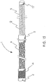
- cerebral vasculature device 1 comprises a proximal portion 2, a first expandable portion 4, a distal portion 3, and atraumatic component 5.
- the device includes a continuous braided structure having an outer diameter, an inner diameter and a lumen that extends from the proximal portion of the continuous braided structure to the distal portion thereof.
- the proximal portion 2 and the distal portion 3 further include polymer 6 imbedded at least partially into the braided structure (shown in Figure 2 ).
- the device 1 further includes core wire 12 having a proximal end and a distal end; the core wire is located within the lumen and extends from the braided structure proximal portion to a point distal to the distal most portion of the braided structure distal portion.
- the core wire 12 can be a ground tapered stainless steel wire, but could also be any number of materials including, but not limited to, nitinol wire, polymeric filament (including, but not limited to, expanded polytetrafluoroethylene (“ePTFE”), polyester, Kevlar® fibers), tubular structures, etc.
- the core wire 12 distal end extends through and is attached to atraumatic component 5, in this case a coil.
- Atraumatic component 5 has an outer diameter at least equal to the inner diameter of the braided structure distal portion 3. Also shown is tip 17 at the distal tip of core wire 12 and atraumatic component 5.
- Figure 2 is a cross-section of the device depicted in Figure 1 taken along A-A, wherein polymer 6 is shown imbedding braided structure 8. Moreover, lumen 7 is shown being defined by the inner diameter of the braided structure 8 and polymer 6. Also shown is core wire 12, located in lumen 7.
- Figure 2A shows an alternative to Figure 2 wherein lumen 7 is defined by an inner polymer layer 6.
- Inner polymer layer 6 can be any suitable polymer material and can be provided as a coating, a thin tube, etc.
- inner polymer layer 6 comprises a lubricious polymer, such as polytetrafluoroethylene.
- inner polymer layer 6 is formed by the same polymer used to imbed the braided structure.
- Inner polymer layer 6 can extend any desired length of the device.
- inner polymer layer 6 extends from the proximal portion 2 to the distal most portion of distal portion 3.
- the proximal portion 2 of the device in Figure 1 can serve as the entire catheter shaft of the device.
- the catheter shaft of the device may comprise a material different from the polymer imbedded braided structure.
- the continuous braided structure can be part of a distal subassembly that may be attached to a suitable proximal catheter assembly.
- the distal subassembly includes proximal portion 2 and distal portion 3, each comprising polymer imbedded at least partially into the braided structure.
- the distal subassembly further includes a first expandable portion 4 located between the proximal portion 2 and the distal portion 3. Further shown is atraumatic component 5. Also shown are core wire 12 and tip 17, located at the distal most portion of the device.
- Catheter shaft 9 can comprise any suitable tubular structure, such as polymer imbedded braided structure, polymer tubing, metal tubing (such as hypo tube), etc.
- the tubular structure can have a change in flexibility from a proximal point to a distal point thereon.
- the distal point of the tubular structure can be more flexible than the proximal point.
- Catheter shaft 9 also includes a lumen which can extend over the entire length of catheter shaft 9.
- catheter shaft 9 will be in communication with the lumen of the distal subassembly, once the catheter shaft 9 and distal subassembly are attached together.
- the catheter shaft 9 and distal subassembly can be either permanently or removably attached together. Any suitable means may be used to attach the catheter shaft 9 and distal subassembly.
- catheter shaft 9 and the distal subassembly are attached by bonding.
- the bond can be supplemented by, for example, crimping or shrink fitting a suitable tubular member over the bond region.
- the bond region between shaft 9 and proximal portion 2 can be covered with a suitable metal tube, shown as 14.
- the metal tube 14 can be compressed into the outer surfaces of each of the shaft 9 and proximal portion 2 to provide a flush outer diameter surface of the device.
- the metal tube 14 can comprise any suitable metal.
- the metal tube 14 comprises radioopaque material.
- polymer tube 15 located over metal tube 14 and the bond region.
- Polymer tube 15 can be any suitable polymer material.
- polymer tube 15 is a shrink-fit polymer tube. The polymer tube 15 can provide further reinforcement to the bond region.
- the catheter shaft 9 is removably attached to the distal subassembly. Therefore, the distal subassembly may be used as an implantable device if desired. For example, it may be desirable to leave in the body the device in its expanded state to act as an occlusive device, to treat aneurysms, to act as a filter, to dilate a vessel, etc.
- the distal subassembly can be made in the same manner previously described; however, a suitable mechanism for removably attaching the subassembly to the catheter shaft can be used. Any suitable means for removably attaching the distal subassembly to the catheter shaft can be used including, but not limited to, electrocorrosive means, mechanical means including friction fit, hook and loops, etc.
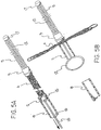
- Figures 5A and 5B demonstrate one exemplary removable attachment embodiment wherein core wire 12 extends in a proximal direction from a point distal to the braided structure distal portion 3, through the expandable portion 4, to a point proximal to proximal portion 2.
- core wire 12 is in the form of a loop, or the core wire 12 can be attached to a loop-shaped wire.
- the loop is sized slightly larger than the inner diameter of the proximal portion 2 so that the proximal portion acts to constrain the loop, as shown in Figure 5A .
- An actuation fiber 16 (or wire) is located through the loop on core wire 12.
- the fiber can be ePTFE fiber.
- Both ends of fiber 16 are pulled through the inner diameter of catheter shaft 9 through to the proximal end of the catheter.
- the expandable portion 4 can be fully actuated by pulling in a proximal direction both ends of the fiber 16, thus pulling the loop in the core wire to a location proximal of the proximal portion. This allows the loop in the core wire to spring open, thus maintaining expandable portion 4 in its expanded configuration, as shown in Figure 5B .
- One end of the fiber 16 is then pulled from the proximal end of the catheter shaft allowing the distal subassembly to be freed from the catheter shaft. This mechanism is also useful in instances where more than one expandable section are present or when the porosity of the expandable section is controlled via a film covering.
- a detachable distal subassembly of particular interest may have two expandable sections in which one section is sized/shaped to fit inside the neck of a cerebral aneurysm and the other section is sized to fit in the parent vessel, thus interrupting flow into the aneurysm.
- Figure 6 demonstrates a still further aspect of the present invention wherein the device includes a second expandable portion 10, located distal to the first expandable portion 4. Also shown is intermediate portion 11, which can comprise polymer imbedded at least partially into the braided structure. Intermediate portion 11 could also be formed or restrained from expansion via various other methods including, but not limited to, a change in braid angle, a marker band, a polymeric film covering, or by heat setting, etc. The intermediate portion 11 can be any suitable length.
- the first expandable portion 4 can be advanced just distal to the thrombus to be removed.
- Both expandable portions 4, 10 can be expanded (i.e., by moving the core wire 12 proximally), and the first expandable portion 4 can be used to pull the thrombus in a proximal direction, with the second expandable portion 10 serving as a safety feature to catch any debris that may break off from the thrombus and float in a distal direction. In an aspect of the invention, this procedure can be carried out under retrograde blood flow conditions to further limit the possibility of debris being carried in a distal direction, toward more delicate vasculature.
- first expandable portion 4 and/or second expandable portion 10 can be provided with an outer polymer cover (discussed in more detail below).
- the intermediate portion 11 can comprise a braided structure having a different braid angle from the braid of the proximal section 2 and the distal section 3.
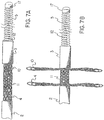
- Figure 7A is an alternative device according to an aspect of the invention.
- the device includes proximal portion 2, expandable portions 4 and 10, with intermediate portion 11 located between the expandable portions 4 and 10.
- the device further includes core wire 12, atraumatic component 5 and tip 17.
- core wire 12 By carefully selecting the braid angle of intermediate portion 11, it is possible to restrain this section from expanding (or limit the degree of expansion relative to the expandable portions 4 and 10) without having to imbed the intermediate braid with polymer or otherwise provide a constraining means.
- Figure 7B is the device with the expandable portions 4 and 10 in their expanded states.
- intermediate portion 11 having the same outer diameter as when the expandable portions 4 and 10 were in their unexpanded states, it is possible to adjust the braid angle of intermediate portion 11 such that the portion expands in diameter any desired amount, thus controlling the distance between the expandable portions 4 and 10 when expanded.
- the distance between two expandable portions can be controlled by providing a second device with a lumen or hollow core wire to allow for an appropriately sized device according to the invention to be advanced through the lumen or hollow core wire to a point distal to the second device.
- a first device comprises proximal portion 2, distal portion 3, and expandable portion 4 located therebetween.
- the first device further includes core wire 12, atraumatic component 5 and tip 17.
- the first device is shown having been at least partially advanced through the lumen of a second device.
- the second device comprises proximal portion 2, distal portion 3, and expandable portion 4.
- the second device also comprises a lumen or hollow core wire (not shown) sized to allow the first device to pass therethrough.
- the second device can include any suitable means to cause expandable portion 4 to expand, and preferably includes an atraumatic component, such as discussed above.
- the second device also includes a core wire (i.e., a hollow core wire), an atraumatic component attached to the core wire, and may also include a tip, as discussed above.
- the tip will also be hollow to allow for advancement of the first device therethrough.
- FIG. 9 there is shown a longitudinal schematic partial cross-section of a device according to an aspect of the invention. Shown in cross-section is proximal portion 2 comprising polymer 6 imbedding the braided structure 8. Also shown is first expandable portion 4 and distal portion 3 comprising polymer imbedding the braided structure. Further shown is core wire 12, extending from the proximal end of the device, through the lumen, and being attached to atraumatic component 5. Atraumatic component 5 has an outer diameter just larger than the inner diameter of distal portion 3. In an aspect of the invention core wire 12 extends from the proximal end of the device, through the lumen, and is attached to the proximal end of atraumatic component 5.
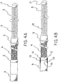
- Figure 10 shows the device of Figure 1 , where the expandable portion 4 is in its fully expanded state.
- Expandable portion 4 can be expanded when core wire 12 is proximally retracted while the braided structure proximal section is held fast.
- the expandable portion 4 is atraumatic to a patient's target vessel when it is in its maximum expanded state.
- the maximum expanded diameter can be equal to or larger than the diameter of the patient's target vessel.
- the first expandable portion (and/or the second expandable portion) can be provided with an outer polymer cover.
- Shown in Figure 11 is an example of such a device. The device is essentially the same as depicted in the figures discussed above, with the addition of the polymer cover 30 surrounding and completely covering the expandable portion.
- Figure 12 shows the device of Figure 11 wherein the expandable portion is in a partially expanded state.
- Any suitable polymer film, tape, etc. can be used to cover the expandable portion in a radially distensible manner.
- suitable polymers include polytetrafluoroethylene (e.g., ePTFE), polyurethane, silicone, polyester, polyethylene, and bioabsorbable polymers.
- Polymer covering can be 100% occlusive in nature, or can have any variation of porosity allowing for a controlled flow rate or particle separation.
- the polymer cover can comprise any suitable number of layers of ePTFE film which can be fused together with heat, then wrapped around expandable portion 4 in such a manner that its microstructure allows the expandable portion 4 to freely radially expand.
- ePTFE polymer covering can comprise interconnected nodes and fibrils, with the covering arranged such that the fibrils are oriented longitudinally when the covering is in its small diameter state. Upon expansion to its larger diameter state, the fibrils can rotate and be oriented more circumferentially. Upon collapse, the ends of the covering can be pulled out as the expandable portion lengthens. This will act to realign the fibrils longitudinally. This same film can then collapse when the expandable portion is allowed to collapse underneath it.
- 4 layers of ePTFE film can be stacked one on top of the other and wrapped around a 5 mm stainless steel mandrel in a "cigarette" wrap configuration, with the film being oriented such that the majority of fibrils are perpendicular to the axis of the mandrel.
- any suitable ePTFE film can be useful, with various wrap orientations as well, particularly attractive is an embodiment that comprises 4 layers of ePTFE film having a density of about 0.3 g/cc, a 50 micron fibril length, and a film thickness of about 0.03 mm.
- the film can be heated at about 370°C for about 25 minutes to fuse together the layers of film, thus forming a tubular wall on one layer.
- the tube can be cut to a length of about 4 inches and removed from the mandrel.
- a 0.012 inch mandrel can then be positioned into the inside diameter of the tubular structure.
- the tubular structure can then be stretched/necked down to a point where the tubular structure's inner diameter is essentially equal to the outer diameter of the mandrel.
- the tubular structure can be removed and positioned over a suitable device according to the invention, with only a slight interference fit.
- Two Pt/Ir marker bands can then be placed over the tubular structure at points located over the proximal portion and the distal portion.
- a radial crimper can be used to crush the Pt/Ir bands down onto the proximal and distal portions of the device.
- the crimping step can be carried out under suitable heat to melt or soften the polymer portion of the proximal and distal portions, thus allowing the bands to be imbedded into the polymer to result in a flush outer surface of the device as well as to increase the strength of the bond.
- the polymer at the proximal and distal portions can comprise PEBAX® 7033 polymer and during the crimping step heat can be applied at 250°F for about 6 seconds under 40 psi of air pressure.
- a steel mandrel can be placed inside the lumen of the device during the crimping step to prevent collapse of the device during heating and crimping.
- the polymer cover need not be bonded to the expandable section. However, as noted above, the polymer cover should be fixedly attached to the proximal and distal portions of the device, but should be free to move over the expandable section.
- the polymer cover 30 can be secured to proximal portion 2 and distal portion 3 in any suitable manner. In an aspect of the invention, as shown in Figures 11 and 12 , the polymer cover is secured to the proximal portion 2 and distal portion 3 using metal tubes 32 and 33, respectively. As mentioned above, the metal tubes 32 and 33 can be compressed into the outer surfaces of each of the proximal portion 2 and distal portion 3 to provide flush outer surfaces on each portion.
- the metal tubes 32 and 33 can comprise any suitable metal. In an aspect of the invention, the metal tubes comprise radioopaque metal.
- the device may be particularly useful in disrupting flow to an aneurysm or across an arterial-venous malformation, or in preventing the distal flow of debris in the case of loose emboli.
- macroporosity may be desired to allow the flow of blood through the device while filtering out debris.
- a film covering having 100 micron pores placed with a laser and an anticoagulant coating could be used to prevent the flow of debris larger than 100 microns.
- Devices embodying this aspect of the invention will be particularly useful due to the small profiles afforded by this invention allowing the devices to be delivered to the neurovasculature through a microcatheter.
- the braided structure of the device can comprise a plurality of wires selected from, for example, the group consisting of round profiles, flat profiles, and combinations thereof.
- a majority of the wires have a round profile.
- the majority of round wires have an outer diameter of about 0.002 inch or less.
- the wires have an outer diameter of 0.0015 inch or less.
- the majority of wires have an outer diameter of about 0.001 inch or less.
- the wires can comprise any suitable material.
- the wires comprise metal.
- Particularly attractive wires can comprise nitinol.
- the wires can comprise radioopaque material.
- the radioopaque material can comprise a metal selected from the group consisting of platinum, iridium, gold and platinum/iridium alloy.
- the braided structure can comprise any number of wires. In an aspect of the invention, the braided structure comprises 32 wires or more. In a further aspect of the invention, the braided structure comprises 48 wires or more. In a still further aspect of the invention, the braided structure comprises 60 wires or more.
- the braided structure can comprise wires oriented at any suitable braiding angle.
- the braided structure of the first expandable portion comprises a plurality of wires oriented at a first angle, while at least a portion of the device comprises braided structure comprising wires oriented at a second angle different from the first angle.
- the braided structure of the first expandable portion comprises wires oriented at an angle of about less than or equal to 10 degrees, as measured from the longitudinal axis of the braided structure.
- the braided structure of the first expandable portion comprises wires oriented at an angle of about less than or equal to 8 degrees, as measured from the longitudinal axis.
- At least a portion of the proximal portion and the distal portion comprise a plurality of wires oriented at the same angle as that of the wires of the first expandable portion.
- at least a portion of the proximal portion comprises a plurality of wires oriented at an angle different from the first expandable portion.
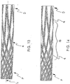
- braided structure 4 comprising braided wires. At the proximal end P of the braided structure, the wires are braided at a first relatively high angle, while the wires at the distal end D are braided at a second, relatively low angle, the braid angles being measured from the longitudinal axis L of the braided structure.
- This aspect of the invention may be particularly useful in that the higher angle braided portion may find utility as a catheter shaft that is more kink resistant than a shaft formed with a relatively lower braid angle.
- the lower braid angle may be particularly useful as the expandable portion (lower braid angles may allow for proper expansion of the expandable portion when compared to higher braid angles).
- a desired braid angle can be obtained using readily available braiding machines by setting the machine setting to a desired pics per inch (PPI) setting.
- PPI pics per inch
- Particularly attractive devices can have an inner diameter of about 0.01 inch and may comprise an expandable portion having a braid angle of about 7 degrees (i.e., about 26 PPI), and a proximal portion having a braid angle of about 21 degrees (i.e., about 80 PPI).
- braided structures according to the invention can be fabricated with any number of sections with varying braid angles.
- the braid angles are obtained by entering settings into the machine.
- use of such machines can result in "transition regions" being formed in the braided structure. As the machine setting changes from one setting to the next, the braid angles will be somewhere between the two set angles in this transition region.
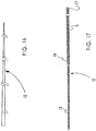
- Such a transition region is shown, generally, as area 18 in Figure 14 .
- Several methods can be used to reduce the size of, eliminate, or cover over the transition region.
- the size of the transition region can be reduced (and even eliminated) by stopping the braiding machine, changing the braid angle setting while the braided structure is held fast, and then restarting the machine.
- the braid will change from a higher angle to a lower angle in less than a centimeter.
- the braid will change from a higher angle to a lower angle in less than 5 mm.
- the braid will change from a higher angle to a lower angle in less than 3 mm.
- the transition region could be covered or partially covered with, for example, a metal or polymer tube or scrimp to add, for example, rigidity to the transition region.
- the braided structure with a transition region could first be at least partially imbedded with suitable polymer, and then a metal tube (preferably a radioopaque material) can be heated and compressed around the transition region of the braided structure to form a suitable device. If the metal tube comprises radioopaque material, the tube can serve as a marker band to help the physician guide the device to a desired target region.
- metal tube 14 has been located over a transition region located just proximal to expandable portion 4.
- the metal tube 14 in this embodiment may also be imbedded into the surface of proximal portion 2 to be flush with the outer diameter of the proximal portion.
- the metal tube can comprise any suitable metal.
- the metal tube comprises radioopaque material.
- an additional marker band can be located distal to the expandable portion 4, if desired.
- the transition region can be eliminated by bonding together two or more sections of braided structure of differing braid angles.
- the polymer imbedded at least partially into the braided structure of the proximal portion, the distal portion, and, when used, the intermediate portion can comprise any suitable polymer material.
- the polymer may comprise a material selected from the group consisting of polyimide, PEBA, polyurethane, nylon, polyethylene, and silicone.
- the polymer can further comprise suitable filler material.
- a suitable polymer can comprise polyimide containing PTFE filler distributed throughout the polymer.
- the polymer substantially completely imbeds the braided structure for essentially the entire length of the proximal portion, the distal portion, and, when used, the intermediate portion.
- an outer polymer layer can be provided to provide the device with a polymer cap.
- the polymer cap will increase the outer diameter of the braided structure and can further modify the properties of the device.
- the polymer should be selected to provide the necessary rigidity to the device to allow the physician to advance the device and also provide structural support to the device so that when the expandable portion is expanded (e.g., by pulling proximally on the proximal end of the core wire) the remainder of the device outer diameter remains substantially unchanged.
- the polymer should also provide the necessary flexibility to the device to allow the device to be advanced through the delicate cerebral vasculature.
- the composition of the polymer can be varied along the length of the device to provide for varying flexibility along the length of the device.
- the polymer material may comprise radioopaque material.
- the polymer may comprise a material selected from the group consisting of barium sulfate, bismuth trioxide, etc.
- the braided structure proximal portion and distal portion can have outer diameters of about 0.020 inch or less. In a further aspect of the invention, the braided structure proximal portion and distal portion can have outer diameters of about 0.017 inch or less.
- the braided structure can have an inner diameter of about 0.010 inch and an outer diameter of about 0.014 inch.
- the polymer can have an inner diameter of about 0.010 inch and an outer diameter of about 0.016 inch when fully impregnating the braided structure, thus providing a 0.001 inch polymer cap around the proximal portion and the distal portion of the braided structure.
- at least some of the polymer can be impregnated to serve as an inner liner for the proximal portion and the distal portion.
- the polymer can define an inner diameter of about 0.010 inch (with the braid having an inner diameter of about 0.011 inch) and an outer diameter of about 0.015 inch.
- the braided structure can have an outer diameter of about 0.015 inch.
- the tubular structure can have essentially the same inner and outer dimensions as the braided structure proximal and distal portions.
- the device includes atraumatic component 5.
- the atraumatic component can be in the form of polymer tubular structures, metal coils, etc.
- the metal may comprise a material selected from the group consisting of, for example, platinum, platinum/iridium, stainless steel, and nitinol.
- the atraumatic component comprises radioopaque platinum/iridium alloy. While the atraumatic component should have an outer diameter larger than the inner diameter of the distal portion, it may also further comprise a section of reduced outer diameter that enters the lumen of the distal portion to aid in centering the core wire in the lumen of the braided structure. This section of the atraumatic component could be a coil of tapering diameter or a second coil, etc.
- the device further includes a core wire that may extend essentially the entire length of the device, wherein the distal end of the core wire is attached to the atraumatic component.
- the core wire can comprise, for example, a material selected from the group consisting of stainless steel and nitinol or from a group of polymeric filaments including ePTFE, polyester, Kevlar® fibers, etc. or a multifiber composite. It can further comprise a tapering outer diameter, resulting in, for example, increasing flexibility of the device distally.
- the distal end of the core wire may contain a section which has been rolled to a rectangular profile allowing for shaping of the atraumatic tip by the physician using standard techniques.
- the core wire can be a tubular structure of any suitable material, such as a polymer tube or a metal tube or a film tube comprised of discrete layers of ePTFE film which have been fused together to form a tube.
- the tubular structure can be solid or hollow.
- the hollow tube can be designed to allow for a second device, or a suitable fluid (such as contrast fluid, an oxygenated fluid, or a thrombolytic agent), to be passed through the tube to a point distal to the distal portion of the cerebral vasculature device.
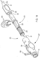
- Shown in Figure 16 is a representative core wire 12.
- the core wire outer diameter is gradually tapered down from a first, relatively larger outer diameter at one end, to a second, relatively smaller outer diameter, to a third relatively even smaller diameter, etc. Any number of distinct tapered sections can be provided, or a relatively constant taper over the entire length of the wire can be provided.
- the core wire 12 can be provided with one or more outer coils 5 and 13 fit over the core wire 12. The outer coils 5 and 13 can be used to vary the stiffness of the core wire along its length, for example.
- the outer coils can be, for example, metal and can be soldered (or otherwise attached, e.g., glued, etc.) to the core wire 12 at one or more points along the length of the core wire.
- the coil(s) can be radioopaque metal such as, for example, platinum, gold, iridium, or platinum/iridium alloy.
- coils 5 and 13 overlap each other and are soldered to core wire 12 at 19.
- coil 5 also includes tip 17 soldered (or otherwise attached) to the distal end of core wire 12.
- coil 5 can be located distal to the distal portion of the braided structure.
- at least a portion of coil 13 can extend proximally into the distal portion of the braided structure when the device is assembled.
- the first expandable portion is expanded when the physician pulls the proximal end of the core wire in a proximal direction while holding the catheter shaft stationary.
- the atraumatic component then applies a proximal force to the distal portion of the device, which results in the first expandable portion radially expanding.
- the polymer imbedded into the braided structure of the proximal portion and the distal portion serves to radially constrain these portions, thus preventing them from expanding.
- the device can further comprise at least one radioopaque marker band.
- the marker bands can be any suitable radioopaque material, such as those described above.
- the at least one radioopaque marker band can lie in a recess provided in the polymer material.
- the at least one radioopaque marker band can be provided proximal and/or distal to the first expandable portion.
- the expandable portion has a length in its unexpanded state of about 1 cm or less. In a further aspect of the invention, the expandable portion has a length of about 5 mm or less. In a still further aspect of the invention, the expandable portion has a length of about 4 mm.
- the expandable portion will radially expand when the core wire is moved in a proximal direction relative to the proximal portion of the device.
- the first expandable portion can have any suitable diameter.
- the maximum expanded diameter of the first expandable portion is about 6 mm or less.
- the maximum diameter of the first expandable portion is about 4 mm or less.
- the maximum diameter of the first expandable portion is about 3.3 mm.
- the device can further include a handle coupled or otherwise attached to the proximal end of the braided structure, or the proximal end of the catheter shaft as the case may be.
- the handle can, in addition to allowing for manipulation of the device through a patient's vasculature, be provided with a mechanism for expanding the expandable portion of the device.
- a suitable handle construction Shown attached to the distal end of the handle 20 is the device shaft or the braided structure proximal portion 2.
- the handle 20 comprises a strain relief section 21 at the distal end of distal housing 22. Coupled to distal housing 22 is proximal handle portion 23 which includes ribbed section 24.
- Pin 26 may be provided to fix core wire 12 to the proximal housing 27.
- Proximal housing 27 fits over proximal portion 23.
- Proximal housing 27 includes cantilever arm 29.
- proximal portion 23 also includes pin or protrusion 25 which is sized to fit into helical slot 30 in proximal housing 27.
- handle 20 can include safety lock/pin 28 and end cap 31, which is insertable into proximal housing 27.
- proximal housing 27 is rotated relative to proximal portion 23 and distal housing 22. Rotation will slowly withdraw core wire 12 and thus cause first expandable portion 4 (and when present, second expandable portion 10) to radially expand.
- the ribbed section 24, along with the cantilever arm 29 allows for incremental locking of the core wire as it is retracted.
- a method for producing the device according to the present invention includes, forming the desired braided structure having a lumen extending for the length thereof.
- the braided structure can then be at least partially (and preferably essentially completely) imbedded with a suitable polymer material, for example, by dip coating the braided structure into a suitable polymer.
- the first expandable portion can be obtained by removing the polymer from a desired length of the braided structure near the distal tip of the structure.
- Suitable methods for removing the polymer include, for example, by laser ablation, abrasion (e.g., micro abrasion methods), etc.
- a suitable atraumatic component can be located at the distal tip of the device (i.e., distal to the distal end of the device).
- the atraumatic component need not be bonded or attached to the distal portion of the device.
- Suitable core wire can then be attached at its distal end to the proximal end of atraumatic component 5 and then inserted through the lumen of the distal section of the device and advanced proximally until the proximal end of the core wire extends through the lumen of the proximal section of the device.
- the core wire can be any suitable material, such as any suitable metal.
- the core wire can be tailored to have a varying stiffness over its length (i.e., relatively stiff at its proximal end to relatively flexible at its distal end).
- the core wire may be attached to atraumatic component in any suitable fashion.
- Nitinol wire can be obtained with a nominal diameter of 0.001 inch from, for example, Fort Wayne Metals (Fort Wayne, IN). This wire can be wound on 16 bobbins, where 3 ends of wire are on each bobbin. This wire can be braided onto a suitable 0.010 inch mandrel (e.g., silver-plated copper) at 26 PPI (or about 7 degrees as measured from the longitudinal axis). The wire can then be dip coated with a PEBAX® 7033 resin so that the resin fully impregnates the braided structure down to the mandrel surface. Multiple dipping/heating steps can be applied until an outer diameter of 0.016 inch is obtained. This tubing can then be cut to 180 cm in length.
- a suitable 0.010 inch mandrel e.g., silver-plated copper
- An excimer laser of suitable wavelength can then be used to fully ablate away the polymer while leaving the wires relatively free from damage in a 4 mm section of tubing located 2 mm from the distal end of the tubing.
- One suitable alternative to laser ablation for removing the polymer to form the expandable portion includes removing the polymer by abrasion utilizing a suitable abrasive material in a high velocity gas stream.
- sodium bicarbonate with an average particle size of 25 microns can be mixed into an airstream at 30 -120 psi and directed to a portion of the tubing through a small orifice. Upon impingement of the surface, the abrasive particles will act to remove the polymer at little or no detriment to the wires.
- a core wire consisting of a 2 meter long stainless steel wire of 0.008 inch diameter can be obtained (for example from Precision Wire Components, PWC, Tualatin, OR).
- the wire can be ground down over its distal 25 cm with a taper to 0.002 inch in diameter.
- the distal 1 cm can be rolled flat with a short edge of 0.001 inch.
- a small coil of 0.0015 inch platinum/iridium alloy wire can be manufactured with a tapering outer diameter of 0.010 inch to 0.007 inch and a length of 11 mm. This coil can be soldered onto the core wire 28 mm from its distal edge.
- Another coil of 0.002 inch platinum/iridium alloy wire can be manufactured to be 33 mm in length with an inner diameter of 0.010 inch. This coil can be positioned over the core wire aligned with the distal tip of the core wire and overlapping the tapered coil by about 5 mm. This can be soldered onto the smaller coil and also to the distal tip of the core wire.
- the proximal end of the core wire can be assembled through the inner diameter of the braided tubing until the tapered coil is pulled into the distal portion of the device, thus centering the core wire in the lumen.
- the device can be used to remove thrombus from very delicate, tortuous cerebral vasculature.
- One method of using the device includes introducing the device using well known techniques (for example, percutaneously introducing the device).
- the device can be advanced to a target region in the cerebral vasculature through the lumen of known microcatheters.
- use of a microcatheter may not be needed if the device is designed to have the necessary flexibility and pushability to be advanced without a microcatheter.
- the device is advanced to the target region while retrograde blood flow is maintained in the target vessel.
- the device can be advanced to a point just proximal to the target region under antegrade blood flow conditions, and under retrograde blood flow conditions as the distal tip of the device crosses the thrombus located in the target region.
- Retrograde blood flow can be obtained by any suitable technique, such as by applying suction to the target vessel, or by natural physiological manipulation using the methods and apparatus taught by, for example, Dorros et al. in US Patent No. 6,929,634 , the subject matter of which is herein incorporated by reference.
- the expandable portion can be expanded and the thrombus pulled back in a proximal direction, preferably still under retrograde blood flow conditions, to remove the thrombus from the patient.
Description
- The present invention relates to devices useful for removing objects such as thrombus/or other foreign bodies from a patient's vasculature. More particularly, the invention relates to devices useful for removing thrombus from a patient's cerebral vasculature.
- The use of a mechanical means to restore patency to obstructed vessels is well known. These devices fit into many categories ranging from hydraulic removal of thrombus, rotating cutting blades for calcified plaque, inflatable means for crushing or dragging thrombus, or a multiplicity of metal structures that either self-expand or can be expanded to dredge a vessel or remove a stone.
- Examples of these devices date back to the 'Fogarty Catheter' described by Fogarty in
US Pat. Nos. 3,367,101 ;3,435,826 ; and4,403,612 describing in detail improvements to a balloon catheter for embolectomy purposes. While suitable for many applications, dragging a balloon through the delicate, tortuous cerebral vasculature is not recommended. Crossing profiles of current state of the art balloon catheters would also limit their use with typical neurovascular accessories (e.g., microcatheters). - Mechanically expanded devices are also well known in the area of obstruction removal. Clark specifically focused on the use of an expanding braid for thrombus removal in
US Pat. No. 3,996,938 . His teaching utilized a braid that would expand under the force of compression delivered by an inner core wire affixed to the distal end of the braid. - Many refinements on this theme have occurred in the areas of stone removal, clot removal, foreign body removal, etc. All of these are assemblies of some nature which either self-expand or mechanically expand under some delivered compressive load. Examples of these can be seen in Bates
US Pat. No. 6,800,080 in which parallel legs of the basket allow bodies to enter the retrieval basket; BatesUS Pat. No. 5,496,330 in which the basket is self-expanding and meant to collapse into a provided sheath;Engelson US Pat. No. 6,066,158 describing a self-expanding conical basket held collapsed in a 'delivered' state because of a 'fixedly attached core wire'; andSamson US Pat. No. 6,066,149 describing an assembly consisting of a series of braided expanders. - These devices, while elegant, fail to address the major concern for applications into the neurovasculature; namely, minimizing the crossing profile (i.e., the cross-sectional area) of the devices. In general, these are all assembled devices consisting of many components that need to either be welded in place, or fixedly attached using collars, etc. It is not seen how a device of these inventions would be compatible with physician preferred microcatheters used to access the delicate, tortuous neurovasculature.
- In many of the inventions, the issue of crossing profile has been circumvented by describing fixed wire assemblies which are not meant to pass through a microcatheter, rather, they are meant to navigate from a large guiding catheter situated well proximal of the obstruction in large vasculature.
Samson US Pat. No. 6,066,149 is an example of this type of assembly. As demonstrated in the figures, the device is an assembly in which the wire ends are managed into a collar. The retractable core wire doubles as a conventional guidewire tip at its distal termination. This tip affords the steering of a guidewire and the ability to puncture a clot to cross it, while the large body of the device encompasses the expander. Perhaps suitable for easily accessible obstructions, this does not address the majority of anticipated cerebral vascular cases, or the physician preference, where a microcatheter/guidewire combination is used to create a pathway across the clot for angiographic visualization distal to the clot prior to the procedure. - Wensel has anticipated the need for smaller devices to achieve neurovasculature compatibility in
US Pat. No. 5,895,398 . In this publication, he teaches the use of a helically shaped wire held straight for delivery by the microcatheter. By using a single wire shaped into a 'cork-screw' he has circumvented the complex assembly steps required in much of the other prior art resulting in large profiles. His invention, unfortunately, places the need of restraint on the microcatheter. Typically, physician preferred microcatheters are extremely flexible at the distal end lending little ability to hold a shaped wire straight. This results in a trade-off of making the 'cork-screw' floppy (which degrades its ability to extract a clot), or making a custom microcatheter which is stiff, limiting procedural access. Wensel's teaching also results in a structure which is not optimized for preventing the distal migration of particulate during the removal of clot due to the inherently large intertices of a device comprised of only a single, helically shaped wire. - The invention relates to cerebral vasculature devices and methods of making the same. The cerebral vasculature device comprises:
- Continuous braided structure comprising a plurality of wires, the braided structure having a proximal portion, a distal portion, a first expandable portion between the proximal portion and the distal portion, and a lumen extending from the proximal portion to the distal portion;
- The proximal portion and the distal portion each having an outer diameter and an inner diameter and further including polymer imbedded at least partially into the braided structure;
- Core wire having a proximal end and a distal end, the core wire located within the lumen and extending from the braided structure proximal portion to a point at or distal to the braided structure distal portion; and
- Atraumatic component attached to the core wire distal end and having an outer diameter at least equal to the inner diameter of the braided structure distal portion.
- The operation of the present invention should become apparent from the following description when considered in conjunction with the accompanying drawings, in which:
-
Figure 1 shows a representative cerebral vasculature device according to an aspect of the invention; -
Figure 2 shows a schematic cross-section of the device ofFigure 1 ; -
Figure 2A shows a variation of the device ofFigure 2 ; -
Figure 3 shows a representative cerebral vasculature distal subassembly device according to an aspect of the invention; -
Figure 4A shows the device ofFigure 3 and a catheter shaft according to an aspect of the invention; -
Figure 4B shows the device ofFigure 4A in its assembled form; -
Figure 5A shows in partial cross-section a further representative device according to an aspect of the invention; -
Figure 5B shows in partial cross-section the device ofFigure 5A with the expandable portion in its expanded state; -
Figure 6 shows a further representative device according to a further aspect of the invention; -
Figures 7A and 7B show a further embodiment according to an aspect of the invention; -
Figure 8 shows a further embodiment according to an aspect of the invention; -
Figure 9 is a longitudinal partial cross-section of a device according to an aspect of the invention; -
Figure 10 shows a device according to an aspect of the invention wherein a first expandable portion is in its expanded state; -
Figure 11 shows a further embodiment of the device according to the invention; -
Figure 12 shows the device ofFigure 11 wherein the first expandable portion is in its expanded state; -
Figure 13 shows a braided construction according to an aspect of the invention; -
Figure 14 shows a braided construction according to an aspect of the invention; -
Figure 15 shows a further representative device according to an aspect of the invention; -
Figure 16 shows a core wire according to an aspect of the invention; -
Figure 17 shows a core wire and atraumatic component assembly according to an aspect of the invention; -
Figure 18 shows an exploded view of a handle assembly according to an aspect of the invention; -
Figure 19 shows a cross-sectional exploded view of the handle assembly shown inFigure 18 ; and -
Figure 20 shows the handle assembly ofFigure 18 , fully assembled. - The cerebral vasculature device comprises:
- Continuous braided structure comprising a plurality of wires, the braided structure having a proximal portion, a distal portion, a first expandable portion between the proximal portion and the distal portion, and a lumen extending from the proximal portion to the distal portion;
- The proximal portion and the distal portion each having an outer diameter and an inner diameter and further including polymer imbedded at least partially into the braided structure;
- Core wire having a proximal end and a distal end, the core wire located within the lumen and extending from the braided structure proximal portion to a point at or distal to the braided structure distal portion; and
- Atraumatic component attached to the core wire distal end and having an outer diameter at least equal to the inner diameter of the braided structure distal portion.
- The invention is best understood with reference to the several figures that demonstrate certain exemplary, non-limiting, aspects of the invention.
- Referring to
Figure 1 , there is shown a cerebral vasculature device 1, according to the present invention. As shown, cerebral vasculature device 1 comprises aproximal portion 2, a firstexpandable portion 4, adistal portion 3, andatraumatic component 5. The device includes a continuous braided structure having an outer diameter, an inner diameter and a lumen that extends from the proximal portion of the continuous braided structure to the distal portion thereof. Theproximal portion 2 and thedistal portion 3 further includepolymer 6 imbedded at least partially into the braided structure (shown inFigure 2 ). The device 1 further includescore wire 12 having a proximal end and a distal end; the core wire is located within the lumen and extends from the braided structure proximal portion to a point distal to the distal most portion of the braided structure distal portion. Thecore wire 12 can be a ground tapered stainless steel wire, but could also be any number of materials including, but not limited to, nitinol wire, polymeric filament (including, but not limited to, expanded polytetrafluoroethylene ("ePTFE"), polyester, Kevlar® fibers), tubular structures, etc. Thecore wire 12 distal end extends through and is attached toatraumatic component 5, in this case a coil. Other suitable materials can be used foratraumatic component 5, such as a polymeric tubular structure.Atraumatic component 5 has an outer diameter at least equal to the inner diameter of the braided structuredistal portion 3. Also shown istip 17 at the distal tip ofcore wire 12 andatraumatic component 5. -
Figure 2 is a cross-section of the device depicted inFigure 1 taken along A-A, whereinpolymer 6 is shown imbedding braidedstructure 8. Moreover, lumen 7 is shown being defined by the inner diameter of thebraided structure 8 andpolymer 6. Also shown iscore wire 12, located in lumen 7. -
Figure 2A shows an alternative toFigure 2 wherein lumen 7 is defined by aninner polymer layer 6.Inner polymer layer 6 can be any suitable polymer material and can be provided as a coating, a thin tube, etc. In an aspect of the invention,inner polymer layer 6 comprises a lubricious polymer, such as polytetrafluoroethylene. In a further aspect of the invention,inner polymer layer 6 is formed by the same polymer used to imbed the braided structure.Inner polymer layer 6 can extend any desired length of the device. In an aspect of the inventioninner polymer layer 6 extends from theproximal portion 2 to the distal most portion ofdistal portion 3. - The
proximal portion 2 of the device inFigure 1 can serve as the entire catheter shaft of the device. In a further aspect of the invention, the catheter shaft of the device may comprise a material different from the polymer imbedded braided structure. In this regard, the continuous braided structure can be part of a distal subassembly that may be attached to a suitable proximal catheter assembly. - Shown in
Figure 3 is a suitable distal subassembly according to an aspect of the present invention. The distal subassembly includesproximal portion 2 anddistal portion 3, each comprising polymer imbedded at least partially into the braided structure. The distal subassembly further includes a firstexpandable portion 4 located between theproximal portion 2 and thedistal portion 3. Further shown isatraumatic component 5. Also shown arecore wire 12 andtip 17, located at the distal most portion of the device. - Turning now to
Figure 4A , shown is the above-described distal subassembly before being attached to catheter shaft 9. Catheter shaft 9 can comprise any suitable tubular structure, such as polymer imbedded braided structure, polymer tubing, metal tubing (such as hypo tube), etc. The tubular structure can have a change in flexibility from a proximal point to a distal point thereon. In an aspect of the invention, the distal point of the tubular structure can be more flexible than the proximal point. Catheter shaft 9 also includes a lumen which can extend over the entire length of catheter shaft 9. The lumen of catheter shaft 9 will be in communication with the lumen of the distal subassembly, once the catheter shaft 9 and distal subassembly are attached together. The catheter shaft 9 and distal subassembly can be either permanently or removably attached together. Any suitable means may be used to attach the catheter shaft 9 and distal subassembly. In an aspect of the invention, catheter shaft 9 and the distal subassembly are attached by bonding. The bond can be supplemented by, for example, crimping or shrink fitting a suitable tubular member over the bond region. For example, as shown inFigure 4B , the bond region between shaft 9 andproximal portion 2 can be covered with a suitable metal tube, shown as 14. Themetal tube 14 can be compressed into the outer surfaces of each of the shaft 9 andproximal portion 2 to provide a flush outer diameter surface of the device. Themetal tube 14 can comprise any suitable metal. In an aspect of the invention, themetal tube 14 comprises radioopaque material. Also shown ispolymer tube 15 located overmetal tube 14 and the bond region.Polymer tube 15 can be any suitable polymer material. In an aspect of the invention,polymer tube 15 is a shrink-fit polymer tube. Thepolymer tube 15 can provide further reinforcement to the bond region. - In an aspect of the invention, the catheter shaft 9 is removably attached to the distal subassembly. Therefore, the distal subassembly may be used as an implantable device if desired. For example, it may be desirable to leave in the body the device in its expanded state to act as an occlusive device, to treat aneurysms, to act as a filter, to dilate a vessel, etc. In these instances, the distal subassembly can be made in the same manner previously described; however, a suitable mechanism for removably attaching the subassembly to the catheter shaft can be used. Any suitable means for removably attaching the distal subassembly to the catheter shaft can be used including, but not limited to, electrocorrosive means, mechanical means including friction fit, hook and loops, etc.
-
Figures 5A and 5B demonstrate one exemplary removable attachment embodiment whereincore wire 12 extends in a proximal direction from a point distal to the braided structuredistal portion 3, through theexpandable portion 4, to a point proximal toproximal portion 2. At a point proximal to theexpandable portion 4,core wire 12 is in the form of a loop, or thecore wire 12 can be attached to a loop-shaped wire. The loop is sized slightly larger than the inner diameter of theproximal portion 2 so that the proximal portion acts to constrain the loop, as shown inFigure 5A . An actuation fiber 16 (or wire) is located through the loop oncore wire 12. In an aspect of the invention, the fiber can be ePTFE fiber. Both ends offiber 16 are pulled through the inner diameter of catheter shaft 9 through to the proximal end of the catheter. Theexpandable portion 4 can be fully actuated by pulling in a proximal direction both ends of thefiber 16, thus pulling the loop in the core wire to a location proximal of the proximal portion. This allows the loop in the core wire to spring open, thus maintainingexpandable portion 4 in its expanded configuration, as shown inFigure 5B . One end of thefiber 16 is then pulled from the proximal end of the catheter shaft allowing the distal subassembly to be freed from the catheter shaft. This mechanism is also useful in instances where more than one expandable section are present or when the porosity of the expandable section is controlled via a film covering. For example, a detachable distal subassembly of particular interest may have two expandable sections in which one section is sized/shaped to fit inside the neck of a cerebral aneurysm and the other section is sized to fit in the parent vessel, thus interrupting flow into the aneurysm. -
Figure 6 demonstrates a still further aspect of the present invention wherein the device includes a secondexpandable portion 10, located distal to the firstexpandable portion 4. Also shown is intermediate portion 11, which can comprise polymer imbedded at least partially into the braided structure. Intermediate portion 11 could also be formed or restrained from expansion via various other methods including, but not limited to, a change in braid angle, a marker band, a polymeric film covering, or by heat setting, etc. The intermediate portion 11 can be any suitable length. When using the device to remove thrombus from the cerebral vasculature, the firstexpandable portion 4 can be advanced just distal to the thrombus to be removed. Bothexpandable portions core wire 12 proximally), and the firstexpandable portion 4 can be used to pull the thrombus in a proximal direction, with the secondexpandable portion 10 serving as a safety feature to catch any debris that may break off from the thrombus and float in a distal direction. In an aspect of the invention, this procedure can be carried out under retrograde blood flow conditions to further limit the possibility of debris being carried in a distal direction, toward more delicate vasculature. Moreover, firstexpandable portion 4 and/or secondexpandable portion 10 can be provided with an outer polymer cover (discussed in more detail below). - In an aspect of the invention (as mentioned above) the intermediate portion 11 can comprise a braided structure having a different braid angle from the braid of the
proximal section 2 and thedistal section 3. For example, shown inFigure 7A is an alternative device according to an aspect of the invention. The device includesproximal portion 2,expandable portions expandable portions core wire 12,atraumatic component 5 andtip 17. By carefully selecting the braid angle of intermediate portion 11, it is possible to restrain this section from expanding (or limit the degree of expansion relative to theexpandable portions 4 and 10) without having to imbed the intermediate braid with polymer or otherwise provide a constraining means. Shown inFigure 7B is the device with theexpandable portions expandable portions expandable portions - In a further aspect of the invention, the distance between two expandable portions can be controlled by providing a second device with a lumen or hollow core wire to allow for an appropriately sized device according to the invention to be advanced through the lumen or hollow core wire to a point distal to the second device. For example, as shown in
Figure 8 , a first device comprisesproximal portion 2,distal portion 3, andexpandable portion 4 located therebetween. The first device further includescore wire 12,atraumatic component 5 andtip 17. The first device is shown having been at least partially advanced through the lumen of a second device. The second device comprisesproximal portion 2,distal portion 3, andexpandable portion 4. The second device also comprises a lumen or hollow core wire (not shown) sized to allow the first device to pass therethrough. The second device can include any suitable means to causeexpandable portion 4 to expand, and preferably includes an atraumatic component, such as discussed above. In an aspect of the invention, the second device also includes a core wire (i.e., a hollow core wire), an atraumatic component attached to the core wire, and may also include a tip, as discussed above. The tip will also be hollow to allow for advancement of the first device therethrough. - Turning now to
Figure 9 , there is shown a longitudinal schematic partial cross-section of a device according to an aspect of the invention. Shown in cross-section isproximal portion 2 comprisingpolymer 6 imbedding thebraided structure 8. Also shown is firstexpandable portion 4 anddistal portion 3 comprising polymer imbedding the braided structure. Further shown iscore wire 12, extending from the proximal end of the device, through the lumen, and being attached toatraumatic component 5.Atraumatic component 5 has an outer diameter just larger than the inner diameter ofdistal portion 3. In an aspect of theinvention core wire 12 extends from the proximal end of the device, through the lumen, and is attached to the proximal end ofatraumatic component 5. -
Figure 10 shows the device ofFigure 1 , where theexpandable portion 4 is in its fully expanded state.Expandable portion 4 can be expanded whencore wire 12 is proximally retracted while the braided structure proximal section is held fast. In an aspect of the invention, theexpandable portion 4 is atraumatic to a patient's target vessel when it is in its maximum expanded state. Moreover, the maximum expanded diameter can be equal to or larger than the diameter of the patient's target vessel. - In a further aspect of the invention, the first expandable portion (and/or the second expandable portion) can be provided with an outer polymer cover. Shown in
Figure 11 is an example of such a device. The device is essentially the same as depicted in the figures discussed above, with the addition of thepolymer cover 30 surrounding and completely covering the expandable portion.Figure 12 shows the device ofFigure 11 wherein the expandable portion is in a partially expanded state. Any suitable polymer film, tape, etc. can be used to cover the expandable portion in a radially distensible manner. For example, suitable polymers include polytetrafluoroethylene (e.g., ePTFE), polyurethane, silicone, polyester, polyethylene, and bioabsorbable polymers. Polymer covering can be 100% occlusive in nature, or can have any variation of porosity allowing for a controlled flow rate or particle separation. - In an aspect of the invention, the polymer cover can comprise any suitable number of layers of ePTFE film which can be fused together with heat, then wrapped around
expandable portion 4 in such a manner that its microstructure allows theexpandable portion 4 to freely radially expand. For example, ePTFE polymer covering can comprise interconnected nodes and fibrils, with the covering arranged such that the fibrils are oriented longitudinally when the covering is in its small diameter state. Upon expansion to its larger diameter state, the fibrils can rotate and be oriented more circumferentially. Upon collapse, the ends of the covering can be pulled out as the expandable portion lengthens. This will act to realign the fibrils longitudinally. This same film can then collapse when the expandable portion is allowed to collapse underneath it. In an exemplary embodiment, 4 layers of ePTFE film can be stacked one on top of the other and wrapped around a 5 mm stainless steel mandrel in a "cigarette" wrap configuration, with the film being oriented such that the majority of fibrils are perpendicular to the axis of the mandrel. Although any suitable ePTFE film can be useful, with various wrap orientations as well, particularly attractive is an embodiment that comprises 4 layers of ePTFE film having a density of about 0.3 g/cc, a 50 micron fibril length, and a film thickness of about 0.03 mm. Once positioned on the mandrel, the film can be heated at about 370°C for about 25 minutes to fuse together the layers of film, thus forming a tubular wall on one layer. The tube can be cut to a length of about 4 inches and removed from the mandrel. A 0.012 inch mandrel can then be positioned into the inside diameter of the tubular structure. The tubular structure can then be stretched/necked down to a point where the tubular structure's inner diameter is essentially equal to the outer diameter of the mandrel. The tubular structure can be removed and positioned over a suitable device according to the invention, with only a slight interference fit. Two Pt/Ir marker bands can then be placed over the tubular structure at points located over the proximal portion and the distal portion. A radial crimper can be used to crush the Pt/Ir bands down onto the proximal and distal portions of the device. The crimping step can be carried out under suitable heat to melt or soften the polymer portion of the proximal and distal portions, thus allowing the bands to be imbedded into the polymer to result in a flush outer surface of the device as well as to increase the strength of the bond. In an aspect of the invention, the polymer at the proximal and distal portions can comprise PEBAX® 7033 polymer and during the crimping step heat can be applied at 250°F for about 6 seconds under 40 psi of air pressure. A steel mandrel can be placed inside the lumen of the device during the crimping step to prevent collapse of the device during heating and crimping. - The polymer cover need not be bonded to the expandable section. However, as noted above, the polymer cover should be fixedly attached to the proximal and distal portions of the device, but should be free to move over the expandable section. The
polymer cover 30 can be secured toproximal portion 2 anddistal portion 3 in any suitable manner. In an aspect of the invention, as shown inFigures 11 and 12 , the polymer cover is secured to theproximal portion 2 anddistal portion 3 usingmetal tubes metal tubes proximal portion 2 anddistal portion 3 to provide flush outer surfaces on each portion. Themetal tubes - By providing the first and/or second expandable portion with a polymer cover, the device may be particularly useful in disrupting flow to an aneurysm or across an arterial-venous malformation, or in preventing the distal flow of debris in the case of loose emboli. In some instances, macroporosity may be desired to allow the flow of blood through the device while filtering out debris. In an aspect of the invention, a film covering having 100 micron pores placed with a laser and an anticoagulant coating could be used to prevent the flow of debris larger than 100 microns. Devices embodying this aspect of the invention will be particularly useful due to the small profiles afforded by this invention allowing the devices to be delivered to the neurovasculature through a microcatheter.
- The braided structure of the device can comprise a plurality of wires selected from, for example, the group consisting of round profiles, flat profiles, and combinations thereof. In an aspect of the invention, a majority of the wires have a round profile. In a further aspect of the invention, the majority of round wires have an outer diameter of about 0.002 inch or less. In a still further aspect of the invention, the wires have an outer diameter of 0.0015 inch or less. In a still further aspect of the invention, the majority of wires have an outer diameter of about 0.001 inch or less.
- The wires can comprise any suitable material. In an aspect of the invention, the wires comprise metal. Particularly attractive wires can comprise nitinol. In a further aspect of the invention, the wires can comprise radioopaque material. In a still further aspect of the invention, the radioopaque material can comprise a metal selected from the group consisting of platinum, iridium, gold and platinum/iridium alloy.
- The braided structure can comprise any number of wires. In an aspect of the invention, the braided structure comprises 32 wires or more. In a further aspect of the invention, the braided structure comprises 48 wires or more. In a still further aspect of the invention, the braided structure comprises 60 wires or more.
- The braided structure can comprise wires oriented at any suitable braiding angle. In an aspect of the invention, the braided structure of the first expandable portion comprises a plurality of wires oriented at a first angle, while at least a portion of the device comprises braided structure comprising wires oriented at a second angle different from the first angle. In a further aspect of the invention, the braided structure of the first expandable portion comprises wires oriented at an angle of about less than or equal to 10 degrees, as measured from the longitudinal axis of the braided structure. In a still further aspect of the invention, the braided structure of the first expandable portion comprises wires oriented at an angle of about less than or equal to 8 degrees, as measured from the longitudinal axis. In a still further aspect of the invention, at least a portion of the proximal portion and the distal portion comprise a plurality of wires oriented at the same angle as that of the wires of the first expandable portion. In a further aspect of the invention, at least a portion of the proximal portion comprises a plurality of wires oriented at an angle different from the first expandable portion. For example, shown in
Figure 13 is braidedstructure 4 comprising braided wires. At the proximal end P of the braided structure, the wires are braided at a first relatively high angle, while the wires at the distal end D are braided at a second, relatively low angle, the braid angles being measured from the longitudinal axis L of the braided structure. This aspect of the invention may be particularly useful in that the higher angle braided portion may find utility as a catheter shaft that is more kink resistant than a shaft formed with a relatively lower braid angle. Moreover, the lower braid angle may be particularly useful as the expandable portion (lower braid angles may allow for proper expansion of the expandable portion when compared to higher braid angles). - It should be understood that a desired braid angle can be obtained using readily available braiding machines by setting the machine setting to a desired pics per inch (PPI) setting. The higher the PPI, the higher the braid angle. Particularly attractive devices can have an inner diameter of about 0.01 inch and may comprise an expandable portion having a braid angle of about 7 degrees (i.e., about 26 PPI), and a proximal portion having a braid angle of about 21 degrees (i.e., about 80 PPI). Thus, using well known braiding machines, braided structures according to the invention can be fabricated with any number of sections with varying braid angles. As mentioned, the braid angles are obtained by entering settings into the machine. Thus, use of such machines can result in "transition regions" being formed in the braided structure. As the machine setting changes from one setting to the next, the braid angles will be somewhere between the two set angles in this transition region.
- Such a transition region is shown, generally, as
area 18 inFigure 14 . Several methods can be used to reduce the size of, eliminate, or cover over the transition region. For example, the size of the transition region can be reduced (and even eliminated) by stopping the braiding machine, changing the braid angle setting while the braided structure is held fast, and then restarting the machine. In an aspect of the invention, the braid will change from a higher angle to a lower angle in less than a centimeter. In a still further aspect of the invention, the braid will change from a higher angle to a lower angle in less than 5 mm. In a still further aspect of the invention, the braid will change from a higher angle to a lower angle in less than 3 mm. - Moreover, the transition region could be covered or partially covered with, for example, a metal or polymer tube or scrimp to add, for example, rigidity to the transition region. Furthermore, the braided structure with a transition region could first be at least partially imbedded with suitable polymer, and then a metal tube (preferably a radioopaque material) can be heated and compressed around the transition region of the braided structure to form a suitable device. If the metal tube comprises radioopaque material, the tube can serve as a marker band to help the physician guide the device to a desired target region.
- The above-described embodiment is shown, for example, in
Figure 15 , wheremetal tube 14 has been located over a transition region located just proximal toexpandable portion 4. As with the use of the metal tube to cover a bond region (discussed above), themetal tube 14 in this embodiment may also be imbedded into the surface ofproximal portion 2 to be flush with the outer diameter of the proximal portion. Thus, providing a relatively smooth, continuous outer surface along the length of the device. Furthermore, the metal tube can comprise any suitable metal. In an aspect of the invention the metal tube comprises radioopaque material. Of course, an additional marker band can be located distal to theexpandable portion 4, if desired. - In an aspect of the invention, the transition region can be eliminated by bonding together two or more sections of braided structure of differing braid angles.
- The polymer imbedded at least partially into the braided structure of the proximal portion, the distal portion, and, when used, the intermediate portion, can comprise any suitable polymer material. For example, the polymer may comprise a material selected from the group consisting of polyimide, PEBA, polyurethane, nylon, polyethylene, and silicone. Moreover, the polymer can further comprise suitable filler material. For example, a suitable polymer can comprise polyimide containing PTFE filler distributed throughout the polymer. In an aspect of the invention, the polymer substantially completely imbeds the braided structure for essentially the entire length of the proximal portion, the distal portion, and, when used, the intermediate portion. Moreover, an outer polymer layer can be provided to provide the device with a polymer cap. The polymer cap will increase the outer diameter of the braided structure and can further modify the properties of the device. The polymer should be selected to provide the necessary rigidity to the device to allow the physician to advance the device and also provide structural support to the device so that when the expandable portion is expanded (e.g., by pulling proximally on the proximal end of the core wire) the remainder of the device outer diameter remains substantially unchanged. Moreover, the polymer should also provide the necessary flexibility to the device to allow the device to be advanced through the delicate cerebral vasculature. Furthermore, the composition of the polymer can be varied along the length of the device to provide for varying flexibility along the length of the device.
- In a further aspect of the invention, the polymer material may comprise radioopaque material. For example, the polymer may comprise a material selected from the group consisting of barium sulfate, bismuth trioxide, etc.
- In an aspect of the invention, the braided structure proximal portion and distal portion can have outer diameters of about 0.020 inch or less. In a further aspect of the invention, the braided structure proximal portion and distal portion can have outer diameters of about 0.017 inch or less.
- In a further aspect of the invention, the braided structure can have an inner diameter of about 0.010 inch and an outer diameter of about 0.014 inch. Moreover, in such an embodiment, the polymer can have an inner diameter of about 0.010 inch and an outer diameter of about 0.016 inch when fully impregnating the braided structure, thus providing a 0.001 inch polymer cap around the proximal portion and the distal portion of the braided structure. In a still further aspect, at least some of the polymer can be impregnated to serve as an inner liner for the proximal portion and the distal portion. In such a case, the polymer can define an inner diameter of about 0.010 inch (with the braid having an inner diameter of about 0.011 inch) and an outer diameter of about 0.015 inch. Moreover, the braided structure can have an outer diameter of about 0.015 inch. Further, when the device proximal portion is attached to a suitable tubular structure (e.g., a catheter shaft), the tubular structure can have essentially the same inner and outer dimensions as the braided structure proximal and distal portions.
- As stated, the device includes
atraumatic component 5. The atraumatic component can be in the form of polymer tubular structures, metal coils, etc. When the atraumatic component comprises metal coil, the metal may comprise a material selected from the group consisting of, for example, platinum, platinum/iridium, stainless steel, and nitinol. In an aspect of the invention, the atraumatic component comprises radioopaque platinum/iridium alloy. While the atraumatic component should have an outer diameter larger than the inner diameter of the distal portion, it may also further comprise a section of reduced outer diameter that enters the lumen of the distal portion to aid in centering the core wire in the lumen of the braided structure. This section of the atraumatic component could be a coil of tapering diameter or a second coil, etc. - The device further includes a core wire that may extend essentially the entire length of the device, wherein the distal end of the core wire is attached to the atraumatic component. The core wire can comprise, for example, a material selected from the group consisting of stainless steel and nitinol or from a group of polymeric filaments including ePTFE, polyester, Kevlar® fibers, etc. or a multifiber composite. It can further comprise a tapering outer diameter, resulting in, for example, increasing flexibility of the device distally. The distal end of the core wire may contain a section which has been rolled to a rectangular profile allowing for shaping of the atraumatic tip by the physician using standard techniques. Moreover, the core wire can be a tubular structure of any suitable material, such as a polymer tube or a metal tube or a film tube comprised of discrete layers of ePTFE film which have been fused together to form a tube. The tubular structure can be solid or hollow. When the tubular structure is hollow, the hollow tube can be designed to allow for a second device, or a suitable fluid (such as contrast fluid, an oxygenated fluid, or a thrombolytic agent), to be passed through the tube to a point distal to the distal portion of the cerebral vasculature device.
- Shown in
Figure 16 is arepresentative core wire 12. As can be seen, the core wire outer diameter is gradually tapered down from a first, relatively larger outer diameter at one end, to a second, relatively smaller outer diameter, to a third relatively even smaller diameter, etc. Any number of distinct tapered sections can be provided, or a relatively constant taper over the entire length of the wire can be provided. As shown inFigure 17 , thecore wire 12 can be provided with one or moreouter coils core wire 12. Theouter coils core wire 12 at one or more points along the length of the core wire. In an aspect of the invention the coil(s) can be radioopaque metal such as, for example, platinum, gold, iridium, or platinum/iridium alloy. As shown, coils 5 and 13 overlap each other and are soldered tocore wire 12 at 19. Moreover, as shown,coil 5 also includestip 17 soldered (or otherwise attached) to the distal end ofcore wire 12. In an aspect of the invention,coil 5 can be located distal to the distal portion of the braided structure. Moreover, at least a portion ofcoil 13 can extend proximally into the distal portion of the braided structure when the device is assembled. - It should now be understood that the first expandable portion is expanded when the physician pulls the proximal end of the core wire in a proximal direction while holding the catheter shaft stationary. The atraumatic component then applies a proximal force to the distal portion of the device, which results in the first expandable portion radially expanding. The polymer imbedded into the braided structure of the proximal portion and the distal portion serves to radially constrain these portions, thus preventing them from expanding.
- The device can further comprise at least one radioopaque marker band. The marker bands can be any suitable radioopaque material, such as those described above. In an aspect of the invention, the at least one radioopaque marker band can lie in a recess provided in the polymer material. The at least one radioopaque marker band can be provided proximal and/or distal to the first expandable portion.
- In an aspect of the invention, the expandable portion has a length in its unexpanded state of about 1 cm or less. In a further aspect of the invention, the expandable portion has a length of about 5 mm or less. In a still further aspect of the invention, the expandable portion has a length of about 4 mm.
- As mentioned above, the expandable portion will radially expand when the core wire is moved in a proximal direction relative to the proximal portion of the device. When expanded, the first expandable portion can have any suitable diameter. In an aspect of the invention, the maximum expanded diameter of the first expandable portion is about 6 mm or less. In a further aspect of the invention, the maximum diameter of the first expandable portion is about 4 mm or less. In a still further aspect of the invention, the maximum diameter of the first expandable portion is about 3.3 mm.
- The device can further include a handle coupled or otherwise attached to the proximal end of the braided structure, or the proximal end of the catheter shaft as the case may be. The handle can, in addition to allowing for manipulation of the device through a patient's vasculature, be provided with a mechanism for expanding the expandable portion of the device. For example, shown in
Figures 18 ,19 , and20 is a suitable handle construction. Shown attached to the distal end of thehandle 20 is the device shaft or the braided structureproximal portion 2. Thehandle 20 comprises astrain relief section 21 at the distal end ofdistal housing 22. Coupled todistal housing 22 isproximal handle portion 23 which includes ribbedsection 24.Pin 26 may be provided to fixcore wire 12 to theproximal housing 27.Proximal housing 27 fits overproximal portion 23.Proximal housing 27 includescantilever arm 29. Moreover,proximal portion 23 also includes pin orprotrusion 25 which is sized to fit intohelical slot 30 inproximal housing 27. Finally, handle 20 can include safety lock/pin 28 andend cap 31, which is insertable intoproximal housing 27. - To operate the
handle 20, safety lock/pin 28 is removed andproximal housing 27 is rotated relative toproximal portion 23 anddistal housing 22. Rotation will slowly withdrawcore wire 12 and thus cause first expandable portion 4 (and when present, second expandable portion 10) to radially expand. Theribbed section 24, along with thecantilever arm 29 allows for incremental locking of the core wire as it is retracted. - A method for producing the device according to the present invention includes, forming the desired braided structure having a lumen extending for the length thereof. The braided structure can then be at least partially (and preferably essentially completely) imbedded with a suitable polymer material, for example, by dip coating the braided structure into a suitable polymer. Once the polymer is cured, the first expandable portion can be obtained by removing the polymer from a desired length of the braided structure near the distal tip of the structure. Suitable methods for removing the polymer include, for example, by laser ablation, abrasion (e.g., micro abrasion methods), etc.
- After removing the polymer to form the first expandable portion, a suitable atraumatic component can be located at the distal tip of the device (i.e., distal to the distal end of the device). The atraumatic component need not be bonded or attached to the distal portion of the device. Suitable core wire can then be attached at its distal end to the proximal end of
atraumatic component 5 and then inserted through the lumen of the distal section of the device and advanced proximally until the proximal end of the core wire extends through the lumen of the proximal section of the device. - The core wire can be any suitable material, such as any suitable metal. The core wire can be tailored to have a varying stiffness over its length (i.e., relatively stiff at its proximal end to relatively flexible at its distal end). The core wire may be attached to atraumatic component in any suitable fashion.
- Without intending to limit the scope of the present invention, the following example illustrates how a device according to the present invention may be made and used.
- Nitinol wire can be obtained with a nominal diameter of 0.001 inch from, for example, Fort Wayne Metals (Fort Wayne, IN). This wire can be wound on 16 bobbins, where 3 ends of wire are on each bobbin. This wire can be braided onto a suitable 0.010 inch mandrel (e.g., silver-plated copper) at 26 PPI (or about 7 degrees as measured from the longitudinal axis). The wire can then be dip coated with a PEBAX® 7033 resin so that the resin fully impregnates the braided structure down to the mandrel surface. Multiple dipping/heating steps can be applied until an outer diameter of 0.016 inch is obtained. This tubing can then be cut to 180 cm in length. An excimer laser of suitable wavelength can then be used to fully ablate away the polymer while leaving the wires relatively free from damage in a 4 mm section of tubing located 2 mm from the distal end of the tubing. One suitable alternative to laser ablation for removing the polymer to form the expandable portion includes removing the polymer by abrasion utilizing a suitable abrasive material in a high velocity gas stream. In one exemplary method, sodium bicarbonate with an average particle size of 25 microns can be mixed into an airstream at 30 -120 psi and directed to a portion of the tubing through a small orifice. Upon impingement of the surface, the abrasive particles will act to remove the polymer at little or no detriment to the wires. A core wire consisting of a 2 meter long stainless steel wire of 0.008 inch diameter can be obtained (for example from Precision Wire Components, PWC, Tualatin, OR). The wire can be ground down over its distal 25 cm with a taper to 0.002 inch in diameter. The distal 1 cm can be rolled flat with a short edge of 0.001 inch. A small coil of 0.0015 inch platinum/iridium alloy wire can be manufactured with a tapering outer diameter of 0.010 inch to 0.007 inch and a length of 11 mm. This coil can be soldered onto the
core wire 28 mm from its distal edge. Another coil of 0.002 inch platinum/iridium alloy wire can be manufactured to be 33 mm in length with an inner diameter of 0.010 inch. This coil can be positioned over the core wire aligned with the distal tip of the core wire and overlapping the tapered coil by about 5 mm. This can be soldered onto the smaller coil and also to the distal tip of the core wire. - The proximal end of the core wire can be assembled through the inner diameter of the braided tubing until the tapered coil is pulled into the distal portion of the device, thus centering the core wire in the lumen.
- The device can be used to remove thrombus from very delicate, tortuous cerebral vasculature. One method of using the device includes introducing the device using well known techniques (for example, percutaneously introducing the device). The device can be advanced to a target region in the cerebral vasculature through the lumen of known microcatheters. Of course, use of a microcatheter may not be needed if the device is designed to have the necessary flexibility and pushability to be advanced without a microcatheter. In an aspect of the invention the device is advanced to the target region while retrograde blood flow is maintained in the target vessel. In a further aspect of the invention, the device can be advanced to a point just proximal to the target region under antegrade blood flow conditions, and under retrograde blood flow conditions as the distal tip of the device crosses the thrombus located in the target region. Retrograde blood flow can be obtained by any suitable technique, such as by applying suction to the target vessel, or by natural physiological manipulation using the methods and apparatus taught by, for example,
Dorros et al. in US Patent No. 6,929,634 , the subject matter of which is herein incorporated by reference. Once the thrombus is crossed by at least the first expandable portion of the device, the expandable portion can be expanded and the thrombus pulled back in a proximal direction, preferably still under retrograde blood flow conditions, to remove the thrombus from the patient. In some instances of well adhered or large thrombus, it may be particularly useful to use the expandable portion of the device to macerate or break apart the thrombus into smaller pieces by cycling the expansion and collapse of the expandable portion of the device. - While particular embodiments of the present invention have been illustrated and described herein, the present invention should not be limited to such illustrations and descriptions. It should be apparent that changes and modifications may be incorporated and embodied as part of the present invention within the scope of the following claims.
Claims (24)
- Cerebral vascular device (1) comprising:continuous braided structure comprising a plurality of wires, the braided structure having a proximal portion (2), a distal portion (3), a first expandable portion (4) between the proximal portion (2) and the distal portion (3), the first expandable portion (4) comprising a plurality of wires oriented at a lower braid angle than the braid angle of at least a portion of the proximal portion relative to the longitudinal axis of the braided structure, wherein the braid angle of the first expandable portion (4) is less than or equal to 10 degrees as measured from the longitudinal axis of the braided structure; and a lumen extending from the proximal portion (2) to the distal portion (3);the proximal portion (2) and the distal portion (3) each having an outer diameter and an inner diameter and further including polymer (6) imbedded at least partially into the braided structure;core wire (12) having a proximal end and a distal end, the core wire (12) located within the lumen and extending from the braided structure proximal portion to a point at or distal to the braided structure distal portion (3); andatraumatic component (5) attached to the core wire (12) distal end and having an outer diameter at least equal to the inner diameter of the braided structure distal portion.
- The cerebral vascular device (1) of claim 1, wherein the braided structure proximal portion and distal portion have an outer diameter of about 0.5mm (0.020 inch) or less.
- The device (1) of claim 1, wherein the plurality of wires comprise metal wires, the wires selected from the group consisting of round profiles and flat profiles and combinations thereof, and optionally wherein the plurality of wires comprise nitinol.
- The device (1) of claim 1, wherein the polymer (6) prevents radial expansion of the braided structure proximal portion (2) and distal portion (3) during expansion of the expandable portion (4).
- The device (1) of claim 1, wherein the polymer (6) substantially completely imbeds the proximal portion (2) and the distal portion (3) of the braided structure.
- The device (1) of claim 1, wherein at least one of the wires comprises radioopaque material or further comprising at least one radiopaque marker band or wherein the polymer comprises radioopaque material.
- The device (1) of claim 1, wherein the device is attached to the distal end of a tubular structure (9) and optionally wherein the tubular structure (9) is a continuation of the proximal portion of the braided structure or wherein the core wire (12) extends for at least the length of the tubular structure (9) and optionally, wherein the combination of the core wire (12) and the tubular structure (9) has a change in flexibility from a proximal point to a distal point thereon or wherein a handle is coupled to the core wire (12) and the tubular structure (9), the handle providing for actuation of the expandable portion.
- The device (1) of claim 1, wherein the first expandable portion (4) has a length in its unexpanded state of about 1cm or less or wherein the expandable portion has a diameter in its maximum expanded state of about 6mm or less.
- The device (1) of claim 1, wherein the plurality of wires numbers 16 wires or more.
- The device (1) of claim 1, wherein the braid angle of the first expandable portion (4) is less than or equal to 8 degrees as measured from the longitudinal axis of the braided structure.
- The device (1) of claim 1, wherein the expandable portion is atraumatic to a patient's vessel when in its maximum expanded state, and optionally wherein the expandable portion is suitable for removing a clot from the patient's vessel.
- The device (1) of claim 1, wherein the braided structure further comprises a second expandable portion (10), and optionally wherein the braided structure further comprises an intermediate portion (11) located between the first expandable portion (4) and the second expandable portion (10) and further optionally wherein the intermediate portion (11) comprises polymer imbedded at least partially into the braided structure or wherein the intermediate portion (11) is radially constrained by a polymer covering or wherein the intermediate portion (11) is radially constrained by a metal band or wherein the intermediate portion (11) is of a higher braid angle than the expandable portions (4, 10).
- The device (1) of claim 1, wherein the device (1) is removably attached to a distal end of a catheter shaft (9).
- The device (1) of claim 1, wherein the first expandable portion (4) is provided with an outer polymer cover (30) and optionally wherein the outer polymer cover (30) comprises ePTFE.
- The device (1) of claim 8, wherein the first expandable portion (4) has a length of about 5mm or less.
- The device (1) of claim 15, wherein the first expandable portion (4) has a length of about 4mm.
- The device (1) of claim 1, wherein the first expandable portion (4) has a diameter in its maximum expandable state of about 6mm or less.
- The device (1) of claim 17, wherein the first expandable portion (4) has a diameter in its maximum expandable state of about 4mm or less.
- The device (1) of claim 18, wherein the first expandable portion (4) has a diameter in its maximum expandable state of about 3.3mm.
- Method for making a cerebral vascular device (1) comprising the steps of:providing a continuous braided structure having a length, a lumen extending therethrough, and having polymer (6) at least partially imbedded therein for substantially the entire length of the braided structure;removing at least a portion of the polymer (6) from the braided structure to form an expandable portion (4), a proximal portion (2)having polymer (6) at least partially imbedded therein and a distal portion (3) having polymer (6) at least partially imbedded therein, the expandable portion (4) being located between the proximal portion (2) and the distal portion (3); the expandable portion (4) comprising a plurality of wires oriented at a lower braid angle than the braid angle of at least a portion of the proximal portion relative to the longitudinal axis of the braided structure, wherein the braid angle of the expandable portion (4) is about less than or equal to 10 degrees as measured from the longitudinal axis of the braided structure;attaching an atraumatic component (5) to a core wire (12), the core wire (12) having a proximal end and a distal end;locating the core wire (12) within the lumen, the core wire (12) extending from the braided structure proximal portion to a point distal to the braided structure distal portion; andwherein the atraumatic component (5) has an outer diameter at least equal to the inner diameter of the braided structure distal portion.
- The method of claim 20, wherein the polymer (6) is provided by a dip-coating process.
- The method of claim 20, wherein the polymer (6) is removed by laser ablation.
- The mtheod of claim 20, wherein the polymer (6) is removed by an abrasion process.
- The mtheod of claim 23, wherein the abrasion process comprises using sodium bicarbonate
Applications Claiming Priority (2)
| Application Number | Priority Date | Filing Date | Title |
|---|---|---|---|
| US11/526,269 US20080097401A1 (en) | 2006-09-22 | 2006-09-22 | Cerebral vasculature device |
| PCT/US2007/017259 WO2008036156A1 (en) | 2006-09-22 | 2007-08-01 | Cerebral vasculature device |
Publications (2)
| Publication Number | Publication Date |
|---|---|
| EP2063791A1 EP2063791A1 (en) | 2009-06-03 |
| EP2063791B1 true EP2063791B1 (en) | 2016-12-21 |
Family
ID=38740353
Family Applications (1)
| Application Number | Title | Priority Date | Filing Date |
|---|---|---|---|
| EP07811013.7A Active EP2063791B1 (en) | 2006-09-22 | 2007-08-01 | Cerebral vasculature device |
Country Status (6)
| Country | Link |
|---|---|
| US (2) | US20080097401A1 (en) |
| EP (1) | EP2063791B1 (en) |
| JP (3) | JP5270554B2 (en) |
| AU (1) | AU2007297811B2 (en) |
| CA (1) | CA2662952C (en) |
| WO (1) | WO2008036156A1 (en) |
Cited By (24)
| Publication number | Priority date | Publication date | Assignee | Title |
|---|---|---|---|---|
| US10905430B2 (en) | 2018-01-24 | 2021-02-02 | DePuy Synthes Products, Inc. | Aneurysm device and delivery system |
| US10939915B2 (en) | 2018-05-31 | 2021-03-09 | DePuy Synthes Products, Inc. | Aneurysm device and delivery system |
| US11058430B2 (en) | 2018-05-25 | 2021-07-13 | DePuy Synthes Products, Inc. | Aneurysm device and delivery system |
| US11076860B2 (en) | 2014-03-31 | 2021-08-03 | DePuy Synthes Products, Inc. | Aneurysm occlusion device |
| US11076861B2 (en) | 2018-10-12 | 2021-08-03 | DePuy Synthes Products, Inc. | Folded aneurysm treatment device and delivery method |
| US11123077B2 (en) | 2018-09-25 | 2021-09-21 | DePuy Synthes Products, Inc. | Intrasaccular device positioning and deployment system |
| US11134953B2 (en) | 2019-02-06 | 2021-10-05 | DePuy Synthes Products, Inc. | Adhesive cover occluding device for aneurysm treatment |
| US11154302B2 (en) | 2014-03-31 | 2021-10-26 | DePuy Synthes Products, Inc. | Aneurysm occlusion device |
| US11272939B2 (en) | 2018-12-18 | 2022-03-15 | DePuy Synthes Products, Inc. | Intrasaccular flow diverter for treating cerebral aneurysms |
| US11278292B2 (en) | 2019-05-21 | 2022-03-22 | DePuy Synthes Products, Inc. | Inverting braided aneurysm treatment system and method |
| US11337706B2 (en) | 2019-03-27 | 2022-05-24 | DePuy Synthes Products, Inc. | Aneurysm treatment device |
| US11406392B2 (en) | 2018-12-12 | 2022-08-09 | DePuy Synthes Products, Inc. | Aneurysm occluding device for use with coagulating agents |
| US11413046B2 (en) | 2019-05-21 | 2022-08-16 | DePuy Synthes Products, Inc. | Layered braided aneurysm treatment device |
| US11457926B2 (en) | 2019-12-18 | 2022-10-04 | DePuy Synthes Products, Inc. | Implant having an intrasaccular section and intravascular section |
| US11471183B1 (en) | 2021-02-18 | 2022-10-18 | Boston Scientific Scimed, Inc. | Thrombectomy methods |
| US11497504B2 (en) | 2019-05-21 | 2022-11-15 | DePuy Synthes Products, Inc. | Aneurysm treatment with pushable implanted braid |
| US11504151B2 (en) | 2021-02-18 | 2022-11-22 | Boston Scientific Scimed, Inc. | Thrombectomy apparatuses |
| US11583282B2 (en) | 2019-05-21 | 2023-02-21 | DePuy Synthes Products, Inc. | Layered braided aneurysm treatment device |
| US11583288B2 (en) | 2018-08-08 | 2023-02-21 | DePuy Synthes Products, Inc. | Delivery of embolic braid |
| US11596412B2 (en) | 2018-05-25 | 2023-03-07 | DePuy Synthes Products, Inc. | Aneurysm device and delivery system |
| US11602350B2 (en) | 2019-12-05 | 2023-03-14 | DePuy Synthes Products, Inc. | Intrasaccular inverting braid with highly flexible fill material |
| US11607226B2 (en) | 2019-05-21 | 2023-03-21 | DePuy Synthes Products, Inc. | Layered braided aneurysm treatment device with corrugations |
| US11672542B2 (en) | 2019-05-21 | 2023-06-13 | DePuy Synthes Products, Inc. | Aneurysm treatment with pushable ball segment |
| US11672543B2 (en) | 2017-02-23 | 2023-06-13 | DePuy Synthes Products, Inc. | Aneurysm method and system |
Families Citing this family (90)
| Publication number | Priority date | Publication date | Assignee | Title |
|---|---|---|---|---|
| US20030187495A1 (en) | 2002-04-01 | 2003-10-02 | Cully Edward H. | Endoluminal devices, embolic filters, methods of manufacture and use |
| US20040093012A1 (en) | 2002-10-17 | 2004-05-13 | Cully Edward H. | Embolic filter frame having looped support strut elements |
| WO2005094283A2 (en) | 2004-03-25 | 2005-10-13 | Hauser David L | Vascular filter device |
| EP1986568B1 (en) | 2006-02-03 | 2017-04-05 | Covidien LP | Methods and devices for restoring blood flow within blocked vasculature |
| US9149609B2 (en) | 2006-10-16 | 2015-10-06 | Embolitech, Llc | Catheter for removal of an organized embolic thrombus |
| US10076346B2 (en) | 2007-04-17 | 2018-09-18 | Covidien Lp | Complex wire formed devices |
| WO2009055782A1 (en) | 2007-10-26 | 2009-04-30 | Possis Medical, Inc. | Intravascular guidewire filter system for pulmonary embolism protection and embolism removal or maceration |
| EP2231037B1 (en) | 2007-12-26 | 2015-08-12 | Lazarus Effect, Inc. | Retrieval systems |
| GB0810749D0 (en) | 2008-06-11 | 2008-07-16 | Angiomed Ag | Catherter delivery device |
| US9750625B2 (en) | 2008-06-11 | 2017-09-05 | C.R. Bard, Inc. | Catheter delivery device |
| EP2403583B1 (en) | 2009-03-06 | 2016-10-19 | Lazarus Effect, Inc. | Retrieval systems |
| US8801748B2 (en) * | 2010-01-22 | 2014-08-12 | Lazarus Effect, Inc. | Retrieval systems and methods for use thereof |
| EP3354210B1 (en) | 2010-09-10 | 2022-10-26 | Covidien LP | Devices for the treatment of vascular defects |
| US8998947B2 (en) | 2010-09-10 | 2015-04-07 | Medina Medical, Inc. | Devices and methods for the treatment of vascular defects |
| US9839540B2 (en) | 2011-01-14 | 2017-12-12 | W. L. Gore & Associates, Inc. | Stent |
| EP2709511A4 (en) * | 2011-05-19 | 2015-04-22 | Boston Scient Ltd | Catheter with a deployable scrubbing assembly |
| ES2683178T3 (en) | 2011-05-23 | 2018-09-25 | Covidien Lp | Extraction systems |
| US11026708B2 (en) | 2011-07-26 | 2021-06-08 | Thrombx Medical, Inc. | Intravascular thromboembolectomy device and method using the same |
| US10342548B2 (en) | 2012-01-13 | 2019-07-09 | W. L. Gore & Associates, Inc. | Occlusion devices and methods of their manufacture and use |
| US9011480B2 (en) | 2012-01-20 | 2015-04-21 | Covidien Lp | Aneurysm treatment coils |
| WO2013119332A2 (en) | 2012-02-09 | 2013-08-15 | Stout Medical Group, L.P. | Embolic device and methods of use |
| EP3572011B1 (en) * | 2012-03-15 | 2022-06-22 | Covidien LP | Devices for the treatment of vascular defects |
| US9687245B2 (en) * | 2012-03-23 | 2017-06-27 | Covidien Lp | Occlusive devices and methods of use |
| JP6295253B2 (en) * | 2012-08-01 | 2018-03-14 | アルスタシス, インコーポレイテッドArstasis, Inc. | Access closure configuration |
| US9308007B2 (en) | 2012-08-14 | 2016-04-12 | W. L. Gore & Associates, Inc. | Devices and systems for thrombus treatment |
| WO2014047650A1 (en) | 2012-09-24 | 2014-03-27 | Inceptus Medical LLC | Device and method for treating vascular occlusion |
| JP2015533555A (en) * | 2012-09-27 | 2015-11-26 | ストライカー コーポレイションStryker Corporation | Method for producing variably reinforced extension medical device |
| US9931193B2 (en) | 2012-11-13 | 2018-04-03 | W. L. Gore & Associates, Inc. | Elastic stent graft |
| US8784434B2 (en) | 2012-11-20 | 2014-07-22 | Inceptus Medical, Inc. | Methods and apparatus for treating embolism |
| US9144492B2 (en) | 2012-12-19 | 2015-09-29 | W. L. Gore & Associates, Inc. | Truncated leaflet for prosthetic heart valves, preformed valve |
| US9101469B2 (en) | 2012-12-19 | 2015-08-11 | W. L. Gore & Associates, Inc. | Prosthetic heart valve with leaflet shelving |
| US9968443B2 (en) | 2012-12-19 | 2018-05-15 | W. L. Gore & Associates, Inc. | Vertical coaptation zone in a planar portion of prosthetic heart valve leaflet |
| US8690907B1 (en) | 2013-03-15 | 2014-04-08 | Insera Therapeutics, Inc. | Vascular treatment methods |
| CN116172656A (en) | 2013-03-15 | 2023-05-30 | 伊瑟拉医疗公司 | Vascular treatment devices and methods |
| US8715314B1 (en) | 2013-03-15 | 2014-05-06 | Insera Therapeutics, Inc. | Vascular treatment measurement methods |
| US8679150B1 (en) | 2013-03-15 | 2014-03-25 | Insera Therapeutics, Inc. | Shape-set textile structure based mechanical thrombectomy methods |
| WO2017142874A2 (en) | 2016-02-16 | 2017-08-24 | Insera Therapeutics, Inc. | Aspiration devices and anchored flow diverting devices |
| US10238406B2 (en) | 2013-10-21 | 2019-03-26 | Inari Medical, Inc. | Methods and apparatus for treating embolism |
| US10842918B2 (en) | 2013-12-05 | 2020-11-24 | W.L. Gore & Associates, Inc. | Length extensible implantable device and methods for making such devices |
| EP3113697B8 (en) | 2014-03-04 | 2019-09-18 | ThrombX Medical, Inc. | Intravascular thromboembolectomy device having a plurality of clot engaging elements |
| US9713475B2 (en) | 2014-04-18 | 2017-07-25 | Covidien Lp | Embolic medical devices |
| EP3136986B1 (en) | 2014-04-30 | 2019-04-17 | Cerus Endovascular Limited | Occlusion device |
| US9060777B1 (en) | 2014-05-28 | 2015-06-23 | Tw Medical Technologies, Llc | Vaso-occlusive devices and methods of use |
| EP3148481A4 (en) | 2014-05-28 | 2017-05-03 | Stryker European Holdings I, LLC | Vaso-occlusive devices and methods of use |
| EP3094363A4 (en) | 2014-06-09 | 2017-10-04 | Inceptus Medical, LLC | Retraction and aspiration device for treating embolism and associated systems and methods |
| US9827094B2 (en) | 2014-09-15 | 2017-11-28 | W. L. Gore & Associates, Inc. | Prosthetic heart valve with retention elements |
| WO2016130647A1 (en) | 2015-02-11 | 2016-08-18 | Lazarus Effect, Inc. | Expandable tip medical devices and methods |
| WO2016182949A1 (en) | 2015-05-08 | 2016-11-17 | Stryker European Holdings I, Llc | Vaso-occlusive devices |
| EP4272660A3 (en) | 2015-07-24 | 2024-01-03 | Ichor Vascular Inc. | Embolectomy system |
| EP3364891B1 (en) | 2015-10-23 | 2023-08-09 | Inari Medical, Inc. | Device for intravascular treatment of vascular occlusion |
| US9700332B2 (en) | 2015-10-23 | 2017-07-11 | Inari Medical, Inc. | Intravascular treatment of vascular occlusion and associated devices, systems, and methods |
| US10342571B2 (en) | 2015-10-23 | 2019-07-09 | Inari Medical, Inc. | Intravascular treatment of vascular occlusion and associated devices, systems, and methods |
| ES2912136T3 (en) | 2015-12-07 | 2022-05-24 | Cerus Endovascular Ltd | occlusion device |
| WO2017106265A1 (en) * | 2015-12-18 | 2017-06-22 | Stryker Corporation | Vaso-occlusive device and delivery assembly |
| CA3016679A1 (en) | 2016-03-11 | 2017-09-14 | Cerus Endovascular Limited | Occlusion device |
| EP4233806A3 (en) | 2016-04-21 | 2023-09-06 | W. L. Gore & Associates, Inc. | Diametrically adjustable endoprostheses |
| US10478195B2 (en) | 2016-08-04 | 2019-11-19 | Covidien Lp | Devices, systems, and methods for the treatment of vascular defects |
| JP6329695B1 (en) * | 2016-10-13 | 2018-05-23 | 朝日インテック株式会社 | Multilayer body, multilayer hollow body, and catheter provided with multilayer hollow body |
| CN110312481B (en) | 2016-10-24 | 2023-04-11 | 伊纳里医疗有限公司 | Devices and methods for treating vascular occlusions |
| CN108272538B (en) * | 2016-12-30 | 2020-06-12 | 先健科技(深圳)有限公司 | Elastic implant for lung volume reduction and lung volume reduction instrument |
| CN113143413B (en) | 2017-05-03 | 2022-06-21 | 美敦力瓦斯科尔勒公司 | Tissue removal catheter with guidewire isolation bushing |
| US11690645B2 (en) | 2017-05-03 | 2023-07-04 | Medtronic Vascular, Inc. | Tissue-removing catheter |
| US11298145B2 (en) | 2017-05-12 | 2022-04-12 | Covidien Lp | Retrieval of material from vessel lumens |
| US11129630B2 (en) | 2017-05-12 | 2021-09-28 | Covidien Lp | Retrieval of material from vessel lumens |
| US10709464B2 (en) | 2017-05-12 | 2020-07-14 | Covidien Lp | Retrieval of material from vessel lumens |
| US11191555B2 (en) | 2017-05-12 | 2021-12-07 | Covidien Lp | Retrieval of material from vessel lumens |
| US10722257B2 (en) | 2017-05-12 | 2020-07-28 | Covidien Lp | Retrieval of material from vessel lumens |
| CN110831523B (en) | 2017-06-12 | 2022-09-13 | 柯惠有限合伙公司 | Tool for sheathing a treatment device, and associated systems and methods |
| US10478322B2 (en) | 2017-06-19 | 2019-11-19 | Covidien Lp | Retractor device for transforming a retrieval device from a deployed position to a delivery position |
| US10575864B2 (en) | 2017-06-22 | 2020-03-03 | Covidien Lp | Securing element for resheathing an intravascular device and associated systems and methods |
| MX2020001999A (en) | 2017-08-21 | 2020-07-20 | Cerus Endovascular Ltd | Occlusion device. |
| US10675036B2 (en) | 2017-08-22 | 2020-06-09 | Covidien Lp | Devices, systems, and methods for the treatment of vascular defects |
| AU2018328011B2 (en) | 2017-09-06 | 2022-09-15 | Inari Medical, Inc. | Hemostasis valves and methods of use |
| JP2020533153A (en) | 2017-09-11 | 2020-11-19 | スロンムエックス メディカル インコーポレイテッドThrombx Medical Inc. | Intravascular thromboembolectomy devices and methods |
| US11020221B2 (en) | 2017-09-27 | 2021-06-01 | W. L. Gore & Associates, Inc. | Prosthetic valve with expandable frame and associated systems and methods |
| CA3078606C (en) | 2017-10-31 | 2023-09-05 | W.L. Gore & Associates, Inc. | Medical valve and leaflet promoting tissue ingrowth |
| WO2019094749A1 (en) * | 2017-11-09 | 2019-05-16 | Contego Medical, Llc | Thrombectomy device and methods of use |
| US11154314B2 (en) | 2018-01-26 | 2021-10-26 | Inari Medical, Inc. | Single insertion delivery system for treating embolism and associated systems and methods |
| EP3813727B1 (en) * | 2018-05-30 | 2023-08-30 | Elum Technologies, Inc. | Integrated thrombectomy and filter device |
| US11383068B2 (en) | 2018-07-20 | 2022-07-12 | eLum Technologies, Inc. | Neurovascular distal access support catheters, aspiration catheters, or device shafts |
| EP3836855A4 (en) | 2018-08-13 | 2022-08-10 | Inari Medical, Inc. | System for treating embolism and associated devices and methods |
| US11357534B2 (en) | 2018-11-16 | 2022-06-14 | Medtronic Vascular, Inc. | Catheter |
| US11678887B2 (en) | 2018-12-17 | 2023-06-20 | Covidien Lp | Devices, systems, and methods for the treatment of vascular defects |
| US11497601B2 (en) | 2019-03-01 | 2022-11-15 | W. L. Gore & Associates, Inc. | Telescoping prosthetic valve with retention element |
| US11819236B2 (en) | 2019-05-17 | 2023-11-21 | Medtronic Vascular, Inc. | Tissue-removing catheter |
| EP3741312A1 (en) | 2019-05-22 | 2020-11-25 | Occlutech Holding AG | Occluder with stretchable waist |
| CN114845648A (en) | 2019-10-16 | 2022-08-02 | 伊纳里医疗有限公司 | Systems, devices, and methods for treating vascular occlusions |
| US11406404B2 (en) | 2020-02-20 | 2022-08-09 | Cerus Endovascular Limited | Clot removal distal protection methods |
| US11931041B2 (en) | 2020-05-12 | 2024-03-19 | Covidien Lp | Devices, systems, and methods for the treatment of vascular defects |
| WO2022046679A1 (en) * | 2020-08-24 | 2022-03-03 | Kuraray Co., Ltd. | Braided cord with changing cross-sectional area and a method of making same |
Citations (3)
| Publication number | Priority date | Publication date | Assignee | Title |
|---|---|---|---|---|
| WO1996025124A1 (en) * | 1995-02-14 | 1996-08-22 | Corvita Corporation | Endovascular stent with locking ring |
| US6632241B1 (en) * | 2000-03-22 | 2003-10-14 | Endovascular Technologies, Inc. | Self-expanding, pseudo-braided intravascular device |
| WO2004112879A1 (en) * | 2003-06-20 | 2004-12-29 | Coloplast A/S | A medical device comprising a braided portion |
Family Cites Families (39)
| Publication number | Priority date | Publication date | Assignee | Title |
|---|---|---|---|---|
| US32005A (en) * | 1861-04-09 | Improvement in construction of salt-kettles | ||
| US3367101A (en) | 1959-05-22 | 1968-02-06 | Spunize Co Of America Inc | Crimped roving or sliver |
| US3435826A (en) * | 1964-05-27 | 1969-04-01 | Edwards Lab Inc | Embolectomy catheter |
| US3467101A (en) * | 1965-09-30 | 1969-09-16 | Edwards Lab Inc | Balloon catheter |
| US3996938A (en) * | 1975-07-10 | 1976-12-14 | Clark Iii William T | Expanding mesh catheter |
| US4403612A (en) * | 1980-10-20 | 1983-09-13 | Fogarty Thomas J | Dilatation method |
| US5230185A (en) | 1990-04-06 | 1993-07-27 | Church & Dwight Co., Inc. | Blasting apparatus and method |
| EP0684787B1 (en) * | 1993-02-19 | 2004-05-12 | Boston Scientific Corporation | Surgical extractor |
| US6123715A (en) * | 1994-07-08 | 2000-09-26 | Amplatz; Curtis | Method of forming medical devices; intravascular occlusion devices |
| US5895398A (en) | 1996-02-02 | 1999-04-20 | The Regents Of The University Of California | Method of using a clot capture coil |
| US6800080B1 (en) * | 1996-05-03 | 2004-10-05 | Scimed Life Systems, Inc. | Medical retrieval device |
| US6096053A (en) * | 1996-05-03 | 2000-08-01 | Scimed Life Systems, Inc. | Medical retrieval basket |
| US5972019A (en) * | 1996-07-25 | 1999-10-26 | Target Therapeutics, Inc. | Mechanical clot treatment device |
| US6066158A (en) * | 1996-07-25 | 2000-05-23 | Target Therapeutics, Inc. | Mechanical clot encasing and removal wire |
| US6059812A (en) * | 1997-03-21 | 2000-05-09 | Schneider (Usa) Inc. | Self-expanding medical device for centering radioactive treatment sources in body vessels |
| US5800525A (en) * | 1997-06-04 | 1998-09-01 | Vascular Science, Inc. | Blood filter |
| US5928260A (en) | 1997-07-10 | 1999-07-27 | Scimed Life Systems, Inc. | Removable occlusion system for aneurysm neck |
| US6174330B1 (en) * | 1997-08-01 | 2001-01-16 | Schneider (Usa) Inc | Bioabsorbable marker having radiopaque constituents |
| US6066149A (en) * | 1997-09-30 | 2000-05-23 | Target Therapeutics, Inc. | Mechanical clot treatment device with distal filter |
| WO1999039649A1 (en) * | 1998-02-10 | 1999-08-12 | Dubrul William R | Occlusion, anchoring, tensioning and flow direction apparatus and methods for use |
| US6117142A (en) * | 1998-03-10 | 2000-09-12 | Cordis Corporation | Embolic coil hydraulic deployment system with improved syringe injector |
| US6450989B2 (en) * | 1998-04-27 | 2002-09-17 | Artemis Medical, Inc. | Dilating and support apparatus with disease inhibitors and methods for use |
| US6331184B1 (en) * | 1999-12-10 | 2001-12-18 | Scimed Life Systems, Inc. | Detachable covering for an implantable medical device |
| IL137326A0 (en) | 2000-07-17 | 2001-07-24 | Mind Guard Ltd | Implantable braided stroke preventing device and method of manufacturing |
| BR0116737A (en) * | 2001-01-09 | 2005-04-12 | Microvention Inc | Embolectomy catheter and system comprising a catheter |
| US6929634B2 (en) | 2001-08-22 | 2005-08-16 | Gore Enterprise Holdings, Inc. | Apparatus and methods for treating stroke and controlling cerebral flow characteristics |
| US6878151B2 (en) * | 2001-09-27 | 2005-04-12 | Scimed Life Systems, Inc. | Medical retrieval device |
| US6638257B2 (en) * | 2002-03-01 | 2003-10-28 | Aga Medical Corporation | Intravascular flow restrictor |
| US20030187495A1 (en) * | 2002-04-01 | 2003-10-02 | Cully Edward H. | Endoluminal devices, embolic filters, methods of manufacture and use |
| JP2005000518A (en) * | 2003-06-13 | 2005-01-06 | National Cardiovascular Center | Manufacturing method for stent, and stent |
| CN1678366B (en) * | 2002-08-23 | 2010-06-09 | 国立循环器病中心总长所代表的日本国 | Stent and process for producing the same |
| US7220271B2 (en) * | 2003-01-30 | 2007-05-22 | Ev3 Inc. | Embolic filters having multiple layers and controlled pore size |
| EP1615689B1 (en) * | 2003-04-09 | 2016-02-03 | Novartis AG | Aerosolization apparatus with capsule puncture alignment guide |
| US20050049577A1 (en) * | 2003-06-20 | 2005-03-03 | Robert Snell | Medical device |
| US20050228434A1 (en) * | 2004-03-19 | 2005-10-13 | Aga Medical Corporation | Multi-layer braided structures for occluding vascular defects |
| US8398670B2 (en) * | 2004-03-19 | 2013-03-19 | Aga Medical Corporation | Multi-layer braided structures for occluding vascular defects and for occluding fluid flow through portions of the vasculature of the body |
| WO2005099365A2 (en) * | 2004-04-08 | 2005-10-27 | Aga Medical Corporation | Flange occlusion devices and methods |
| US20060149312A1 (en) * | 2004-12-30 | 2006-07-06 | Edward Arguello | Distal protection device with improved wall apposition |
| US20070149996A1 (en) * | 2005-12-28 | 2007-06-28 | Medtronic Vascular, Inc. | Low profile filter |
-
2006
- 2006-09-22 US US11/526,269 patent/US20080097401A1/en not_active Abandoned
-
2007
- 2007-08-01 WO PCT/US2007/017259 patent/WO2008036156A1/en active Application Filing
- 2007-08-01 JP JP2009529172A patent/JP5270554B2/en not_active Expired - Fee Related
- 2007-08-01 EP EP07811013.7A patent/EP2063791B1/en active Active
- 2007-08-01 CA CA2662952A patent/CA2662952C/en not_active Expired - Fee Related
- 2007-08-01 AU AU2007297811A patent/AU2007297811B2/en not_active Ceased
-
2012
- 2012-11-22 JP JP2012256284A patent/JP5718884B2/en not_active Expired - Fee Related
-
2014
- 2014-11-06 US US14/535,253 patent/US9622770B2/en active Active
- 2014-11-18 JP JP2014233574A patent/JP2015057110A/en not_active Ceased
Patent Citations (3)
| Publication number | Priority date | Publication date | Assignee | Title |
|---|---|---|---|---|
| WO1996025124A1 (en) * | 1995-02-14 | 1996-08-22 | Corvita Corporation | Endovascular stent with locking ring |
| US6632241B1 (en) * | 2000-03-22 | 2003-10-14 | Endovascular Technologies, Inc. | Self-expanding, pseudo-braided intravascular device |
| WO2004112879A1 (en) * | 2003-06-20 | 2004-12-29 | Coloplast A/S | A medical device comprising a braided portion |
Cited By (27)
| Publication number | Priority date | Publication date | Assignee | Title |
|---|---|---|---|---|
| US11076860B2 (en) | 2014-03-31 | 2021-08-03 | DePuy Synthes Products, Inc. | Aneurysm occlusion device |
| US11154302B2 (en) | 2014-03-31 | 2021-10-26 | DePuy Synthes Products, Inc. | Aneurysm occlusion device |
| US11890020B2 (en) | 2017-02-23 | 2024-02-06 | DePuy Synthes Products, Inc. | Intrasaccular aneurysm treatment device with varying coatings |
| US11672543B2 (en) | 2017-02-23 | 2023-06-13 | DePuy Synthes Products, Inc. | Aneurysm method and system |
| US10905430B2 (en) | 2018-01-24 | 2021-02-02 | DePuy Synthes Products, Inc. | Aneurysm device and delivery system |
| US11672540B2 (en) | 2018-01-24 | 2023-06-13 | DePuy Synthes Products, Inc. | Aneurysm device and delivery system |
| US11058430B2 (en) | 2018-05-25 | 2021-07-13 | DePuy Synthes Products, Inc. | Aneurysm device and delivery system |
| US11596412B2 (en) | 2018-05-25 | 2023-03-07 | DePuy Synthes Products, Inc. | Aneurysm device and delivery system |
| US10939915B2 (en) | 2018-05-31 | 2021-03-09 | DePuy Synthes Products, Inc. | Aneurysm device and delivery system |
| US11583288B2 (en) | 2018-08-08 | 2023-02-21 | DePuy Synthes Products, Inc. | Delivery of embolic braid |
| US11123077B2 (en) | 2018-09-25 | 2021-09-21 | DePuy Synthes Products, Inc. | Intrasaccular device positioning and deployment system |
| US11076861B2 (en) | 2018-10-12 | 2021-08-03 | DePuy Synthes Products, Inc. | Folded aneurysm treatment device and delivery method |
| US11633191B2 (en) | 2018-10-12 | 2023-04-25 | DePuy Synthes Products, Inc. | Folded aneurysm treatment device and delivery method |
| US11406392B2 (en) | 2018-12-12 | 2022-08-09 | DePuy Synthes Products, Inc. | Aneurysm occluding device for use with coagulating agents |
| US11272939B2 (en) | 2018-12-18 | 2022-03-15 | DePuy Synthes Products, Inc. | Intrasaccular flow diverter for treating cerebral aneurysms |
| US11134953B2 (en) | 2019-02-06 | 2021-10-05 | DePuy Synthes Products, Inc. | Adhesive cover occluding device for aneurysm treatment |
| US11337706B2 (en) | 2019-03-27 | 2022-05-24 | DePuy Synthes Products, Inc. | Aneurysm treatment device |
| US11583282B2 (en) | 2019-05-21 | 2023-02-21 | DePuy Synthes Products, Inc. | Layered braided aneurysm treatment device |
| US11497504B2 (en) | 2019-05-21 | 2022-11-15 | DePuy Synthes Products, Inc. | Aneurysm treatment with pushable implanted braid |
| US11607226B2 (en) | 2019-05-21 | 2023-03-21 | DePuy Synthes Products, Inc. | Layered braided aneurysm treatment device with corrugations |
| US11672542B2 (en) | 2019-05-21 | 2023-06-13 | DePuy Synthes Products, Inc. | Aneurysm treatment with pushable ball segment |
| US11413046B2 (en) | 2019-05-21 | 2022-08-16 | DePuy Synthes Products, Inc. | Layered braided aneurysm treatment device |
| US11278292B2 (en) | 2019-05-21 | 2022-03-22 | DePuy Synthes Products, Inc. | Inverting braided aneurysm treatment system and method |
| US11602350B2 (en) | 2019-12-05 | 2023-03-14 | DePuy Synthes Products, Inc. | Intrasaccular inverting braid with highly flexible fill material |
| US11457926B2 (en) | 2019-12-18 | 2022-10-04 | DePuy Synthes Products, Inc. | Implant having an intrasaccular section and intravascular section |
| US11504151B2 (en) | 2021-02-18 | 2022-11-22 | Boston Scientific Scimed, Inc. | Thrombectomy apparatuses |
| US11471183B1 (en) | 2021-02-18 | 2022-10-18 | Boston Scientific Scimed, Inc. | Thrombectomy methods |
Also Published As
| Publication number | Publication date |
|---|---|
| JP2013056201A (en) | 2013-03-28 |
| US9622770B2 (en) | 2017-04-18 |
| US20080097401A1 (en) | 2008-04-24 |
| CA2662952A1 (en) | 2008-03-27 |
| CA2662952C (en) | 2014-07-08 |
| JP5270554B2 (en) | 2013-08-21 |
| WO2008036156A1 (en) | 2008-03-27 |
| AU2007297811A1 (en) | 2008-03-27 |
| EP2063791A1 (en) | 2009-06-03 |
| AU2007297811B2 (en) | 2011-04-28 |
| JP5718884B2 (en) | 2015-05-13 |
| JP2015057110A (en) | 2015-03-26 |
| US20150127035A1 (en) | 2015-05-07 |
| JP2010504145A (en) | 2010-02-12 |
Similar Documents
| Publication | Publication Date | Title |
|---|---|---|
| US9622770B2 (en) | Cerebral vasculature device | |
| EP1589900B1 (en) | Embolic filters with a distal loop | |
| US11607301B2 (en) | Intravascular blood filters and methods of use | |
| US6730104B1 (en) | Methods and devices for removing an obstruction from a blood vessel | |
| EP2283892B1 (en) | Retrieval device for withdrawing a protection device from a body lumen | |
| US6663652B2 (en) | Distal protection device and method | |
| US7780696B2 (en) | Distal protection device and method | |
| EP3925572A1 (en) | Intravascular blood filters | |
| US20060229658A1 (en) | Embolic protection filter with reduced landing zone | |
| EP1684646A1 (en) | Clot removal device | |
| EP2047822A2 (en) | Embolic protection device having a filter frame with integral distal strain relief | |
| CN115192282A (en) | Delivery of medical devices |
Legal Events
| Date | Code | Title | Description |
|---|---|---|---|
| PUAI | Public reference made under article 153(3) epc to a published international application that has entered the european phase |
Free format text: ORIGINAL CODE: 0009012 |
|
| 17P | Request for examination filed |
Effective date: 20090310 |
|
| AK | Designated contracting states |
Kind code of ref document: A1 Designated state(s): AT BE BG CH CY CZ DE DK EE ES FI FR GB GR HU IE IS IT LI LT LU LV MC MT NL PL PT RO SE SI SK TR |
|
| AX | Request for extension of the european patent |
Extension state: AL BA HR MK RS |
|
| 17Q | First examination report despatched |
Effective date: 20120228 |
|
| DAX | Request for extension of the european patent (deleted) | ||
| RAP1 | Party data changed (applicant data changed or rights of an application transferred) |
Owner name: W.L. GORE & ASSOCIATES, INC. |
|
| GRAP | Despatch of communication of intention to grant a patent |
Free format text: ORIGINAL CODE: EPIDOSNIGR1 |
|
| INTG | Intention to grant announced |
Effective date: 20160929 |
|
| GRAS | Grant fee paid |
Free format text: ORIGINAL CODE: EPIDOSNIGR3 |
|
| STAA | Information on the status of an ep patent application or granted ep patent |
Free format text: STATUS: GRANT OF PATENT IS INTENDED |
|
| GRAA | (expected) grant |
Free format text: ORIGINAL CODE: 0009210 |
|
| STAA | Information on the status of an ep patent application or granted ep patent |
Free format text: STATUS: THE PATENT HAS BEEN GRANTED |
|
| AK | Designated contracting states |
Kind code of ref document: B1 Designated state(s): AT BE BG CH CY CZ DE DK EE ES FI FR GB GR HU IE IS IT LI LT LU LV MC MT NL PL PT RO SE SI SK TR |
|
| REG | Reference to a national code |
Ref country code: GB Ref legal event code: FG4D |
|
| REG | Reference to a national code |
Ref country code: CH Ref legal event code: EP |
|
| REG | Reference to a national code |
Ref country code: IE Ref legal event code: FG4D |
|
| REG | Reference to a national code |
Ref country code: AT Ref legal event code: REF Ref document number: 854771 Country of ref document: AT Kind code of ref document: T Effective date: 20170115 |
|
| REG | Reference to a national code |
Ref country code: DE Ref legal event code: R096 Ref document number: 602007049255 Country of ref document: DE |
|
| PG25 | Lapsed in a contracting state [announced via postgrant information from national office to epo] |
Ref country code: LV Free format text: LAPSE BECAUSE OF FAILURE TO SUBMIT A TRANSLATION OF THE DESCRIPTION OR TO PAY THE FEE WITHIN THE PRESCRIBED TIME-LIMIT Effective date: 20161221 |
|
| REG | Reference to a national code |
Ref country code: LT Ref legal event code: MG4D |
|
| REG | Reference to a national code |
Ref country code: NL Ref legal event code: MP Effective date: 20161221 |
|
| PG25 | Lapsed in a contracting state [announced via postgrant information from national office to epo] |
Ref country code: GR Free format text: LAPSE BECAUSE OF FAILURE TO SUBMIT A TRANSLATION OF THE DESCRIPTION OR TO PAY THE FEE WITHIN THE PRESCRIBED TIME-LIMIT Effective date: 20170322 Ref country code: LT Free format text: LAPSE BECAUSE OF FAILURE TO SUBMIT A TRANSLATION OF THE DESCRIPTION OR TO PAY THE FEE WITHIN THE PRESCRIBED TIME-LIMIT Effective date: 20161221 Ref country code: SE Free format text: LAPSE BECAUSE OF FAILURE TO SUBMIT A TRANSLATION OF THE DESCRIPTION OR TO PAY THE FEE WITHIN THE PRESCRIBED TIME-LIMIT Effective date: 20161221 |
|
| REG | Reference to a national code |
Ref country code: AT Ref legal event code: MK05 Ref document number: 854771 Country of ref document: AT Kind code of ref document: T Effective date: 20161221 |
|
| PG25 | Lapsed in a contracting state [announced via postgrant information from national office to epo] |
Ref country code: FI Free format text: LAPSE BECAUSE OF FAILURE TO SUBMIT A TRANSLATION OF THE DESCRIPTION OR TO PAY THE FEE WITHIN THE PRESCRIBED TIME-LIMIT Effective date: 20161221 |
|
| PG25 | Lapsed in a contracting state [announced via postgrant information from national office to epo] |
Ref country code: NL Free format text: LAPSE BECAUSE OF FAILURE TO SUBMIT A TRANSLATION OF THE DESCRIPTION OR TO PAY THE FEE WITHIN THE PRESCRIBED TIME-LIMIT Effective date: 20161221 |
|
| REG | Reference to a national code |
Ref country code: FR Ref legal event code: PLFP Year of fee payment: 11 |
|
| PG25 | Lapsed in a contracting state [announced via postgrant information from national office to epo] |
Ref country code: CZ Free format text: LAPSE BECAUSE OF FAILURE TO SUBMIT A TRANSLATION OF THE DESCRIPTION OR TO PAY THE FEE WITHIN THE PRESCRIBED TIME-LIMIT Effective date: 20161221 Ref country code: SK Free format text: LAPSE BECAUSE OF FAILURE TO SUBMIT A TRANSLATION OF THE DESCRIPTION OR TO PAY THE FEE WITHIN THE PRESCRIBED TIME-LIMIT Effective date: 20161221 Ref country code: IS Free format text: LAPSE BECAUSE OF FAILURE TO SUBMIT A TRANSLATION OF THE DESCRIPTION OR TO PAY THE FEE WITHIN THE PRESCRIBED TIME-LIMIT Effective date: 20170421 Ref country code: EE Free format text: LAPSE BECAUSE OF FAILURE TO SUBMIT A TRANSLATION OF THE DESCRIPTION OR TO PAY THE FEE WITHIN THE PRESCRIBED TIME-LIMIT Effective date: 20161221 Ref country code: RO Free format text: LAPSE BECAUSE OF FAILURE TO SUBMIT A TRANSLATION OF THE DESCRIPTION OR TO PAY THE FEE WITHIN THE PRESCRIBED TIME-LIMIT Effective date: 20161221 |
|
| PG25 | Lapsed in a contracting state [announced via postgrant information from national office to epo] |
Ref country code: PT Free format text: LAPSE BECAUSE OF FAILURE TO SUBMIT A TRANSLATION OF THE DESCRIPTION OR TO PAY THE FEE WITHIN THE PRESCRIBED TIME-LIMIT Effective date: 20170421 Ref country code: BE Free format text: LAPSE BECAUSE OF FAILURE TO SUBMIT A TRANSLATION OF THE DESCRIPTION OR TO PAY THE FEE WITHIN THE PRESCRIBED TIME-LIMIT Effective date: 20161221 Ref country code: ES Free format text: LAPSE BECAUSE OF FAILURE TO SUBMIT A TRANSLATION OF THE DESCRIPTION OR TO PAY THE FEE WITHIN THE PRESCRIBED TIME-LIMIT Effective date: 20161221 Ref country code: PL Free format text: LAPSE BECAUSE OF FAILURE TO SUBMIT A TRANSLATION OF THE DESCRIPTION OR TO PAY THE FEE WITHIN THE PRESCRIBED TIME-LIMIT Effective date: 20161221 Ref country code: BG Free format text: LAPSE BECAUSE OF FAILURE TO SUBMIT A TRANSLATION OF THE DESCRIPTION OR TO PAY THE FEE WITHIN THE PRESCRIBED TIME-LIMIT Effective date: 20170321 Ref country code: AT Free format text: LAPSE BECAUSE OF FAILURE TO SUBMIT A TRANSLATION OF THE DESCRIPTION OR TO PAY THE FEE WITHIN THE PRESCRIBED TIME-LIMIT Effective date: 20161221 |
|
| REG | Reference to a national code |
Ref country code: DE Ref legal event code: R097 Ref document number: 602007049255 Country of ref document: DE |
|
| PLBE | No opposition filed within time limit |
Free format text: ORIGINAL CODE: 0009261 |
|
| STAA | Information on the status of an ep patent application or granted ep patent |
Free format text: STATUS: NO OPPOSITION FILED WITHIN TIME LIMIT |
|
| 26N | No opposition filed |
Effective date: 20170922 |
|
| PG25 | Lapsed in a contracting state [announced via postgrant information from national office to epo] |
Ref country code: DK Free format text: LAPSE BECAUSE OF FAILURE TO SUBMIT A TRANSLATION OF THE DESCRIPTION OR TO PAY THE FEE WITHIN THE PRESCRIBED TIME-LIMIT Effective date: 20161221 |
|
| PG25 | Lapsed in a contracting state [announced via postgrant information from national office to epo] |
Ref country code: SI Free format text: LAPSE BECAUSE OF FAILURE TO SUBMIT A TRANSLATION OF THE DESCRIPTION OR TO PAY THE FEE WITHIN THE PRESCRIBED TIME-LIMIT Effective date: 20161221 |
|
| REG | Reference to a national code |
Ref country code: CH Ref legal event code: PL |
|
| PG25 | Lapsed in a contracting state [announced via postgrant information from national office to epo] |
Ref country code: MC Free format text: LAPSE BECAUSE OF FAILURE TO SUBMIT A TRANSLATION OF THE DESCRIPTION OR TO PAY THE FEE WITHIN THE PRESCRIBED TIME-LIMIT Effective date: 20161221 |
|
| PG25 | Lapsed in a contracting state [announced via postgrant information from national office to epo] |
Ref country code: CH Free format text: LAPSE BECAUSE OF NON-PAYMENT OF DUE FEES Effective date: 20170831 Ref country code: LI Free format text: LAPSE BECAUSE OF NON-PAYMENT OF DUE FEES Effective date: 20170831 |
|
| REG | Reference to a national code |
Ref country code: IE Ref legal event code: MM4A |
|
| PG25 | Lapsed in a contracting state [announced via postgrant information from national office to epo] |
Ref country code: LU Free format text: LAPSE BECAUSE OF NON-PAYMENT OF DUE FEES Effective date: 20170801 |
|
| REG | Reference to a national code |
Ref country code: FR Ref legal event code: PLFP Year of fee payment: 12 |
|
| PG25 | Lapsed in a contracting state [announced via postgrant information from national office to epo] |
Ref country code: IE Free format text: LAPSE BECAUSE OF NON-PAYMENT OF DUE FEES Effective date: 20170801 |
|
| PG25 | Lapsed in a contracting state [announced via postgrant information from national office to epo] |
Ref country code: MT Free format text: LAPSE BECAUSE OF NON-PAYMENT OF DUE FEES Effective date: 20170801 |
|
| PG25 | Lapsed in a contracting state [announced via postgrant information from national office to epo] |
Ref country code: HU Free format text: LAPSE BECAUSE OF FAILURE TO SUBMIT A TRANSLATION OF THE DESCRIPTION OR TO PAY THE FEE WITHIN THE PRESCRIBED TIME-LIMIT; INVALID AB INITIO Effective date: 20070801 |
|
| PG25 | Lapsed in a contracting state [announced via postgrant information from national office to epo] |
Ref country code: CY Free format text: LAPSE BECAUSE OF NON-PAYMENT OF DUE FEES Effective date: 20161221 |
|
| PG25 | Lapsed in a contracting state [announced via postgrant information from national office to epo] |
Ref country code: TR Free format text: LAPSE BECAUSE OF FAILURE TO SUBMIT A TRANSLATION OF THE DESCRIPTION OR TO PAY THE FEE WITHIN THE PRESCRIBED TIME-LIMIT Effective date: 20161221 |
|
| P01 | Opt-out of the competence of the unified patent court (upc) registered |
Effective date: 20230516 |
|
| PGFP | Annual fee paid to national office [announced via postgrant information from national office to epo] |
Ref country code: IT Payment date: 20230720 Year of fee payment: 17 Ref country code: GB Payment date: 20230720 Year of fee payment: 17 |
|
| PGFP | Annual fee paid to national office [announced via postgrant information from national office to epo] |
Ref country code: FR Payment date: 20230720 Year of fee payment: 17 Ref country code: DE Payment date: 20230720 Year of fee payment: 17 |