EP2063644A2 - Image encoding device and encoding method, and image decoding device and decoding method - Google Patents
Image encoding device and encoding method, and image decoding device and decoding method Download PDFInfo
- Publication number
- EP2063644A2 EP2063644A2 EP20080253486 EP08253486A EP2063644A2 EP 2063644 A2 EP2063644 A2 EP 2063644A2 EP 20080253486 EP20080253486 EP 20080253486 EP 08253486 A EP08253486 A EP 08253486A EP 2063644 A2 EP2063644 A2 EP 2063644A2
- Authority
- EP
- European Patent Office
- Prior art keywords
- prediction
- image
- encoding
- variable
- unit
- Prior art date
- Legal status (The legal status is an assumption and is not a legal conclusion. Google has not performed a legal analysis and makes no representation as to the accuracy of the status listed.)
- Withdrawn
Links
Images






Classifications
-
- H—ELECTRICITY
- H04—ELECTRIC COMMUNICATION TECHNIQUE
- H04N—PICTORIAL COMMUNICATION, e.g. TELEVISION
- H04N19/00—Methods or arrangements for coding, decoding, compressing or decompressing digital video signals
- H04N19/10—Methods or arrangements for coding, decoding, compressing or decompressing digital video signals using adaptive coding
- H04N19/134—Methods or arrangements for coding, decoding, compressing or decompressing digital video signals using adaptive coding characterised by the element, parameter or criterion affecting or controlling the adaptive coding
- H04N19/136—Incoming video signal characteristics or properties
- H04N19/14—Coding unit complexity, e.g. amount of activity or edge presence estimation
-
- G—PHYSICS
- G06—COMPUTING OR CALCULATING; COUNTING
- G06N—COMPUTING ARRANGEMENTS BASED ON SPECIFIC COMPUTATIONAL MODELS
- G06N3/00—Computing arrangements based on biological models
- G06N3/02—Neural networks
- G06N3/08—Learning methods
- G06N3/084—Backpropagation, e.g. using gradient descent
-
- H—ELECTRICITY
- H04—ELECTRIC COMMUNICATION TECHNIQUE
- H04N—PICTORIAL COMMUNICATION, e.g. TELEVISION
- H04N19/00—Methods or arrangements for coding, decoding, compressing or decompressing digital video signals
- H04N19/10—Methods or arrangements for coding, decoding, compressing or decompressing digital video signals using adaptive coding
- H04N19/102—Methods or arrangements for coding, decoding, compressing or decompressing digital video signals using adaptive coding characterised by the element, parameter or selection affected or controlled by the adaptive coding
- H04N19/103—Selection of coding mode or of prediction mode
- H04N19/11—Selection of coding mode or of prediction mode among a plurality of spatial predictive coding modes
-
- H—ELECTRICITY
- H04—ELECTRIC COMMUNICATION TECHNIQUE
- H04N—PICTORIAL COMMUNICATION, e.g. TELEVISION
- H04N19/00—Methods or arrangements for coding, decoding, compressing or decompressing digital video signals
- H04N19/10—Methods or arrangements for coding, decoding, compressing or decompressing digital video signals using adaptive coding
- H04N19/102—Methods or arrangements for coding, decoding, compressing or decompressing digital video signals using adaptive coding characterised by the element, parameter or selection affected or controlled by the adaptive coding
- H04N19/13—Adaptive entropy coding, e.g. adaptive variable length coding [AVLC] or context adaptive binary arithmetic coding [CABAC]
-
- H—ELECTRICITY
- H04—ELECTRIC COMMUNICATION TECHNIQUE
- H04N—PICTORIAL COMMUNICATION, e.g. TELEVISION
- H04N19/00—Methods or arrangements for coding, decoding, compressing or decompressing digital video signals
- H04N19/10—Methods or arrangements for coding, decoding, compressing or decompressing digital video signals using adaptive coding
- H04N19/169—Methods or arrangements for coding, decoding, compressing or decompressing digital video signals using adaptive coding characterised by the coding unit, i.e. the structural portion or semantic portion of the video signal being the object or the subject of the adaptive coding
- H04N19/17—Methods or arrangements for coding, decoding, compressing or decompressing digital video signals using adaptive coding characterised by the coding unit, i.e. the structural portion or semantic portion of the video signal being the object or the subject of the adaptive coding the unit being an image region, e.g. an object
- H04N19/176—Methods or arrangements for coding, decoding, compressing or decompressing digital video signals using adaptive coding characterised by the coding unit, i.e. the structural portion or semantic portion of the video signal being the object or the subject of the adaptive coding the unit being an image region, e.g. an object the region being a block, e.g. a macroblock
-
- H—ELECTRICITY
- H04—ELECTRIC COMMUNICATION TECHNIQUE
- H04N—PICTORIAL COMMUNICATION, e.g. TELEVISION
- H04N19/00—Methods or arrangements for coding, decoding, compressing or decompressing digital video signals
- H04N19/50—Methods or arrangements for coding, decoding, compressing or decompressing digital video signals using predictive coding
- H04N19/593—Methods or arrangements for coding, decoding, compressing or decompressing digital video signals using predictive coding involving spatial prediction techniques
-
- H—ELECTRICITY
- H04—ELECTRIC COMMUNICATION TECHNIQUE
- H04N—PICTORIAL COMMUNICATION, e.g. TELEVISION
- H04N19/00—Methods or arrangements for coding, decoding, compressing or decompressing digital video signals
- H04N19/60—Methods or arrangements for coding, decoding, compressing or decompressing digital video signals using transform coding
-
- H—ELECTRICITY
- H04—ELECTRIC COMMUNICATION TECHNIQUE
- H04N—PICTORIAL COMMUNICATION, e.g. TELEVISION
- H04N19/00—Methods or arrangements for coding, decoding, compressing or decompressing digital video signals
- H04N19/60—Methods or arrangements for coding, decoding, compressing or decompressing digital video signals using transform coding
- H04N19/61—Methods or arrangements for coding, decoding, compressing or decompressing digital video signals using transform coding in combination with predictive coding
Definitions
- the present invention relates to an image encoding technology for encoding an image such as a moving picture or still-frame picture, and an image decoding technology for decoding the image encoded.
- the encoding schemes such as MPEG (: Moving Picture Experts Group) schemes had been formulated, and have become internationally-standardized encoding schemes as MPEG-1 standard, MPEG-2 standard, MPEG-4 standard, and H.264/AVC (: Advanced Video Coding) standard.
- MPEG-1 standard MPEG-1 standard
- MPEG-2 standard MPEG-2 standard
- MPEG-4 standard MPEG-4 standard
- H.264/AVC Advanced Video Coding
- an encoding target image is predicted in a block unit by taking advantage of image information whose encoding processing is completed. Then, a prediction difference between the original image and the encoding target image predicted in this way is encoded. By doing this prediction-difference encoding, redundancy which the moving picture possesses is eliminated thereby to reduce the resultant code amount.
- the intra-frame prediction encoding scheme is employed which takes advantage of peripheral pixels on the periphery of the encoding target block. The employment of this intra-frame prediction encoding scheme has allowed the implementation of a dramatic enhancement in the compression ratio.
- one reference pixel is selected from among pixels included in a pre-encoded block. Then, all of the pixels existing along a certain specific prediction direction are predicted using the pixel value of this reference pixel. At this time, the prediction accuracy is enhanced by making the specific prediction direction, which is suitable for the image, selectable from among a plurality of prediction directions defined in advance. In this case, however, a code for representing the prediction direction is required to be added for each block which becomes the prediction unit. Accordingly, there has existed a problem that the code amount increases by the amount equivalent to this addition of the code.
- JP-A-2007-116351 (paragraphs 0009, 0020, 0027), the proposal has been made concerning an image prediction decoding method which is designed to implement an efficient decoding processing by reducing mode information about prediction methods.
- this image prediction decoding method the following prediction method is further derived: Namely, based on pre-processed data corresponding to an adjacent region adjacent to an encoding target region and including pre-reproduced pixel signals, this prediction method generates an intra-frame prediction signal having a high pixel-signal correlation with the adjacent region from among a plurality of predetermined prediction methods.
- the mode information about the prediction method i.e., direction
- JP-A-2004-129260 (paragraph 0026) the disclosure has been made concerning a method for performing space prediction encoding and decoding of the color-phase component of an intra image. Namely, if the prediction mode is not included in the bit stream, variation amounts in vertical and horizontal directions of the pixel values with respect to the present block are calculated by taking advantage of reconstructed reference blocks on the upper side and side-surface sides of the present block. Then, the prediction method is determined based on these variation amounts.
- the compression efficiency may be enhanced by decreasing the prediction-direction representing code amount.
- the prediction direction in an encoding target block i.e., a block which becomes the target of the intra-frame prediction encoding processing
- the prediction direction in an encoding target block is estimated by taking advantage of pre-encoded blocks which are adjacent to the encoding target block. For example, a Sobel filter is applied to each of decoded images in four pre-encoded blocks which are adjacent to the left side, upper-left side, upper side, and upper-right side of the encoding target block, thereby calculating edge information which includes intensities and angles of the edges.
- the degree of likelihood of each prediction direction is calculated, using parameters of these eight intensities and angles obtained by this calculation.
- the prediction direction whose degree of likelihood is the highest is employed as the prediction direction in the encoding target block.
- the employment of the prediction direction like this makes it unnecessary to add the prediction-direction representing code to the bit stream.
- the present invention is also effective to direction-independent intra-frame prediction schemes such as, e.g., the DC prediction in H.264/AVC. Accordingly, its application to these schemes makes it possible to expect a significant reduction in the code amount.
- a variable-length code table is dynamically created based on the above-described estimated result. The creation of this table also allows implementation of a significant reduction in the prediction-direction representing code amount. As a result, it becomes possible to expect an enhancement in the compression efficiency.
- taking advantage of, e.g., a neural network is effective to the above-described likelihood-degree calculation in each prediction direction.
- Fig. 3 is a conceptual diagram for explaining the intra-frame prediction encoding processing according to H.264/AVC.
- the encoding is executed with respect to an encoding target image in accordance with the sequence of the raster scanning (301). Then, the prediction is performed using decoded images in four pre-encoded blocks which are adjacent to the left side, upper-left side, upper side, and upper-right side of the encoding target block.
- thirteen decoded pixels included in these four blocks are taken advantage of (302).
- the thirteen pixels are the pixels which, of the pixels included in the four blocks, are arranged in a manner of being adjacent to the encoding target block.
- these thirteen pixels are as follows: In the left side block, the four pixels on the right-most longitudinal line; in the upper-left side block, the one pixel at the lower-right corner; and in the upper side and upper-right side blocks, the four pixels arranged transversely on the lower-most side each.
- the direction of the prediction-direction vector is a downward direction
- all of the longitudinally-arranged four pixels B, C, D, and E in the encoding target block are subjected to the prediction encoding by making reference to one and the same reference pixel (i.e., the value A' obtained by decoding the pixel positioned directly above the pixel B) which exists on the prediction-direction vector in the upper side block (here, the prediction for the pixels B, C, D, and E is made by being assumed to be the same value as the value A', namely, each of the predicted pixel values for B, C, D, and E is equal to the value A').
- differences i.e., prediction differences
- b, c, d, and e between the pixels B, C, D, and E and the predicted pixel value A' are calculated.
- an optimum prediction-direction vector can be selected in the block unit from among eight types of prediction-direction candidates such as longitudinal, transverse, and oblique prediction directions (i.e., the directions indicated by the arrows of 0, 1, and 3 to 8 in Fig. 3 ).
- "DC prediction” can also be taken advantage of (304) in addition to the above-described prediction made along the specific prediction direction.
- the DC prediction all of the pixels included in the encoding target block are predicted using an average value of the reference pixels.
- the prediction direction 2 is allocated to the DC prediction.
- prediction modes that are represented in a manner of being distinguished by the above-described nine types of numbers (i.e., the eight directions + the DC prediction)
- information for indicating which of the prediction modes has been selected is encoded along with the prediction differences b, c, d, and e.
- Fig. 4 is a conceptual diagram for explaining the intra-frame prediction decoding processing according to H.264/AVC.
- the decoding is executed in accordance with the sequence of the raster scanning (401). Then, processing steps which are inverse to the encoding processing are executed, using a pre-decoded reference pixel and prediction differences. Namely, in a decoding target block, in accordance with the prediction mode selected at the time of the encoding processing and along the prediction direction corresponding thereto, the prediction differences (decoded values) are added to the reference pixel, thereby acquiring the decoded image.
- a summation is calculated between prediction differences b', c', d', and e' in the decoding target block (each of which results from decoding each of the prediction differences b, c, d, and e illustrated in Fig. 3 , and each of which contains a quantization error) and the reference pixels A'all of which have been pre-decoded, thereby acquiring decoded pixels B', C', D', and E' (each of which is the decoded pixel corresponding to each of B, C, D, and E in Fig. 3 ).
- the single-direction-based prediction encoding method is employed where one reference pixel is specified, and where all of the pixels existing along a specific prediction direction are predicted using the pixel value of this reference pixel.
- the information for indicating in which direction the prediction will be made has been required to be added for each encoding target block which becomes the unit of the prediction processing.
- Figs. 5A and 5B illustrate the encoding method for the prediction mode in the intra-frame prediction scheme according to H.264/AVC.
- H.264/AVC attention is focused on the fact that the prediction mode in the encoding target block is highly correlated with the prediction modes in the pre-encoded blocks adjacent thereto. Accordingly, the prediction mode in the encoding target block is predicted from the prediction modes in the pre-encoded adjacent blocks. Namely, as is indicated by (501), reference is made to the prediction mode M A in the adjacent block A which is adjacent to the left side of the encoding target block, and the prediction mode M B in the adjacent block B which is adjacent to the upper side of the encoding target block.
- the prediction mode whose number (i.e., one of the nine types of numbers illustrated in Fig. 3 (Fig. 4 )) is smaller of these two prediction modes M A and M B is employed as the prediction value (most probable mode) of the prediction mode in the encoding target block (502).
- the reference numeral (503) in Fig. 5B illustrates details of the bit configuration which represents the prediction method.
- the use of a flag (1 bit) for indicating whether or not the prediction mode is the same as the most probable mode encodes information for indicating that the prediction mode is the same as the most probable mode (i.e., code of "1" as the flag).
- the use of the flag encodes information for indicating that the prediction mode is different from the most probable mode (i.e., code of "0" as the flag).
- the actual prediction mode (of the nine-way prediction modes, one of the eight-way prediction modes excluding the most probable mode) is encoded with 3 bits.
- the representation of the prediction mode requires the use of a large amount of code. For example, when the intra-frame prediction is made in the 4-pixel x 4-pixel-size block unit, a 64-bit code occurs at the maximum per macro block.
- Figs. 6A and 6B are conceptual diagrams for illustrating an embodiment of the encoding processing for the prediction mode according to the present invention.
- the prediction mode in the encoding (decoding) target block is estimated by taking advantage of decoded images in the pre-encoded adjacent blocks A, B, C, and D which are adjacent to the left side, upper-left side, upper side, and upper-right side of the encoding (decoding) target block.
- the prediction mode in the target block is identified by taking advantage of a function f for inputting edge information on the adjacent blocks A to D, and outputting the prediction mode in the target block (602). Taking advantage of this function f makes it unnecessary to encode the prediction mode. As a result, the bit amount needed for representing the prediction mode becomes equal to zero (603).
- a detection method for detecting the above-described edge information is not particularly specified, taking advantage of, e.g., a Sobel filter illustrated in Fig. 14A is quite effective.
- two types of Sobel filters i.e., a vertical-direction-use Sobel filter (1401) and a horizontal-direction-use Sobel filter (1402), are used, thereby detecting the edges in the respective directions.
- the use of a Prewitt filter is allowable.
- oblique-direction-use filters 1405) and (1406) are prepared.
- MIN-MAX filter a rectangular filter in a specific size is prepared at first, then calculating a difference between the maximum value and the minimum value of the concentration value therein.
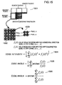
- Fig. 15 illustrates an example of the calculation method for calculating the edge information including edge intensities and edge angles in the case of taking advantage of the Sobel filters (1401) and (1402).
- the decoded images in the pre-encoded adjacent blocks A, B, C, and D which are adjacent to the left side, upper-left side, upper side, and upper-right side of the encoding (decoding) target block (1501)
- four pixels i.e., pixel 1 to pixel 4
- the vertical-direction-use filter (1401) and the horizontal-direction-use filter (1402) are applied to these four pixels.
- edges intensity can be calculated as is given by, e.g., (1504), and the edge angles can be calculated as are given by, e.g., (1505) and (1506).
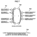
- Fig. 7 illustrates an example of the case where the function f is implemented taking advantage of the neural network.
- the neural network refers to a network where a plurality of threshold-value logic units are hierarchically deployed from an input layer to an output layer.
- a connection between the units exists only between layers adjacent to each other, and the connection is a one-direction connection directed from the input layer to the output layer.
- a weight of the connection is allocated to between the connected units.
- an input into a unit deployed in a higher-order hierarchy becomes equal to a summation of the products of values outputted by a group of units deployed in a lower-order hierarchy and the weights of the connections between the units.
- these weights are adjusted so that a desirable result will be obtained in the output layer.
- a function which will return the prediction-mode number in which the highest degree of likelihood is outputted is set as the above-described function f (704).
- This setting allows implementation of the encoding and decoding processings based on the method illustrated in Figs. 6A and 6B .
- the learning method to be used for the above-described learning is not particularly specified, taking advantage of, e.g., the BP (: Back Propagation) method permits accomplishment of an outstanding effect. Concerning the BP method, the detailed explanation has been given in, e.g., Chapter 3 of the following document:
- the candidates for the above-described function f are widely conceivable, ranging from a simple polynomial where the edge intensities and angles are employed as the variable to a function where the mechanical learning techniques are used such as kernel method, SVM (: Support Vector Machine), k-nearest neighbor algorithm, linear determinant analysis, Baysian network, Hidden Markov Model, and decision-tree learning. Also, a plurality of identification devices may be combined by a method of using boosting or the like. With which of the models the function f is to be implemented, or what type of input/output the function f is to perform may be determined by a standard in advance, or it is all right to permit the information on the function f to be stored into the stream.
- the mechanical learning techniques such as kernel method, SVM (: Support Vector Machine), k-nearest neighbor algorithm, linear determinant analysis, Baysian network, Hidden Markov Model, and decision-tree learning.
- a plurality of identification devices may be combined by a method of using boosting or the like. With which
- the edge intensities and angles of the central four pixels in the adjacent blocks are used as the variables.
- information on the peripheral blocks such as pixel-value average, variance, standard deviation, encoding method, and prediction mode of the peripheral blocks. Otherwise, it is all right to add image parameters on the encoding condition such as QP (: Quantization Parameter) and frame resolution.
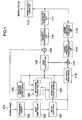
- Fig. 1 is a block diagram for illustrating an embodiment of the moving-picture encoding device according to the present invention.
- the moving-picture encoding device includes an original-image memory (102) for storing original images (101) inputted, a block partition unit (103) for partitioning each of the inputted original images (101) into small regions, a motion search unit (104) for detecting a motion in the block unit, a prediction-mode estimation unit (105) for estimating a prediction direction in the intra-frame prediction, an intra-frame prediction unit (106) for making the intra-frame prediction in the block unit, an inter-frame prediction unit (107) for making an inter-frame prediction in the block unit and based on the motion amount detected by the motion search unit (104), a mode selection unit (108) for determining a prediction encoding scheme (i.e., prediction method and block size) which matches property of the image, a subtraction unit (109) for generating prediction differences, a frequency transformation unit (110) and a quantization processing unit (111) for performing an encoding with respect to the
- the original-image memory (102) stores a piece of image from among the original images (101) as an encoding target image.
- the block partition unit (103) partitions this encoding target image into small blocks, then transferring these small blocks to the motion search unit (104), the intra-frame prediction unit (106), and the inter-frame prediction unit (107).
- the motion search unit (104) calculates a motion amount in the blocks by using the pre-decoded image stored in the reference-image memory (116), then transferring the corresponding motion vector to the inter-frame prediction unit (107).
- the prediction-mode estimation unit (105) extracts, from the reference-image memory (116), decoded images in the pre-encoded blocks positioned on the periphery of the target block, then performing the edge detection to identify the prediction direction in the target block, and transferring the identified prediction direction to the intra-frame prediction unit (106).
- the intra-frame prediction unit (106) and the inter-frame prediction unit (107) execute the intra-frame prediction processing and the inter-frame prediction processing in the block units in several sizes.
- the mode selection unit (108) selects an optimum prediction method which is either the intra-frame prediction method or the inter-frame prediction method.
- the subtraction unit (109) generates the prediction differences based on the optimum prediction encoding scheme, then transferring the generated prediction differences to the frequency transformation unit (110).
- the frequency transformation unit (110) and the quantization processing unit (111) apply a frequency transformation such as the DCT (: Discrete Cosine Transformation) and a quantization processing respectively to the transferred prediction differences in the block unit in a specified size, then transferring the resultant after-quantized frequency transformation coefficients to the variable length coding unit (112) and the inverse quantization processing unit (113).
- variable length coding unit (112) performs the variable length coding with respect to the prediction-difference information represented by the after-quantized frequency transformation coefficients, thereby generating an encoded stream.
- this variable length coding is performed along with the variable length coding of the information needed for the prediction decoding, such as the prediction direction in the intra-frame prediction encoding and the motion vector in the inter-frame prediction encoding.
- the inverse quantization processing unit (113) and the inverse frequency transformation unit (114) apply an inverse quantization processing and an inverse frequency transformation such as the IDCT (: Inverse DCT) respectively to the after-quantized frequency transformation coefficients, thereby acquiring the prediction differences, and then transferring the acquired prediction differences to the addition unit (115). Subsequently, the addition unit (115) generates the decoded image, which is then stored into the reference-image memory (116).
- direction-independent intra-frame prediction schemes such as, e.g., the DC prediction in H.264/AVC may also be employed as the target of the estimation.
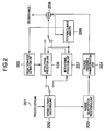
- Fig. 2 is a block diagram for illustrating an embodiment of the moving-picture decoding device according to the present invention.
- the moving-picture decoding device includes, e.g., a variable-length decoding unit (202) for performing an inverse processing step to the variable length coding with respect to the encoded stream (201) which is generated by the moving-picture encoding device illustrated in Fig.
- an inverse quantization processing unit (203) and an inverse frequency transformation unit (204) for decoding the prediction differences for decoding the prediction differences
- a prediction-mode estimation unit (205) for estimating a prediction direction in the intra-frame prediction
- an intra-frame prediction unit (206) for making the intra-frame prediction
- an inter-frame prediction unit (207) for making an inter-frame prediction
- an addition unit (208) for acquiring a decoded image
- a reference-image memory (209) for storing the decoded image temporarily.
- the variable-length decoding unit (202) performs the variable-length decoding with respect to the encoded stream (201), thereby acquiring the frequency transformation coefficient components of the prediction differences, and the information needed for the prediction processing such as the block size and the motion vector.
- the former information i.e., the prediction-difference information is transferred to the inverse quantization processing unit (203).
- the latter information i.e., the information needed for the prediction processing is transferred to either the intra-frame prediction unit (206) or the inter-frame prediction unit (207), depending on the prediction scheme.
- the inverse quantization processing unit (203) and the inverse frequency transformation unit (204) apply the inverse quantization processing and the inverse frequency transformation respectively to the prediction-difference information, thereby performing the decoding.
- the prediction-mode estimation unit (205) extracts, from the reference-image memory (209), the decoded images in the pre-encoded blocks positioned on the periphery of the target block, then performing the edge detection to identify the prediction direction in the target block, and transferring the identified prediction direction to the intra-frame prediction unit (206). Subsequently, the intra-frame prediction unit (206) or the inter-frame prediction unit (207) executes the prediction processing by making reference to the reference-image memory (209) on the basis of the information transferred from the variable-length decoding unit (202). Moreover, the addition unit (208) generates the decoded image, which is then stored into the reference-image memory (209).
- the moving-picture decoding device itself includes the prediction-mode estimation unit (205) and the prediction units (206) and (207) subsequent thereto.
- the prediction processing by which the prediction direction in the target block is identified is executed from the signal decoded from the encoded stream. Consequently, there exists no necessity for adding a prediction-mode representing code to the encoded stream. This feature allows implementation of a reduction in the code amount at the time of encoding and decoding the image.
- Fig. 8 is a flowchart for illustrating 1-frame encoding processing steps in the embodiment of the moving-picture encoding device illustrated in Fig. 1 .
- the processing in a loop 1 where each processing up to a processing (814) described hereinafter is repeated, is performed.
- the processing in a loop 2 where each processing from a processing (803) to a processing (806 or 807) is repeated with respect to all the coding modes, is further performed.
- the prediction differences are calculated with respect to the encoding target block by performing the prediction encoding processing with respect to all the coding modes (i.e., combinations of the prediction methods and the block sizes) once temporarily.
- the coding mode which results in the highest encoding efficiency is selected.
- the intra-frame prediction encoding processing (806) and the inter-frame prediction encoding processing (807) are executed, then selecting an optimum prediction processing method from these processings. This selection allows implementation of a high-efficiency encoding in correspondence with the property of the image.
- the intra-frame prediction mode (803) when performing the intra-frame prediction encoding processing (806), the edge included in the pre-encoded blocks positioned on the periphery of the target block is detected using the Sobel filter or the like (804).
- the prediction direction in the target block is identified by taking advantage of, e.g., the function F illustrated in (704) (805).
- the coding mode which results in the highest encoding efficiency is selected from among the large number of coding modes (808), taking advantage of, e.g., the RD-Optimization scheme allows implementation of the high-efficiency encoding.
- the optimum coding mode is determined from the relationship between image-quality distortion and the code amount. Concerning the details of the RD-Optimization scheme, the description has been given in the following document:
- the prediction differences generated in the selected optimum coding mode are subjected to the frequency transformation (809) and the quantization processing (810), then being further subjected to the variable length coding thereby to generate the encoded stream (811).
- the inverse quantization processing (812) and the inverse frequency transformation (813) are applied to the pre-quantized frequency transformation coefficients, thereby decoding the prediction differences.
- the decoded image is generated, then being stored into the reference-image memory (814).
- Fig. 9 is a flowchart for illustrating 1-frame decoding processing steps in the embodiment of the moving-picture decoding device illustrated in Fig. 2 .
- the processing in a loop 1 where each processing from a processing (902) to a processing (908 or 909) described hereinafter is repeated, is performed.
- the inputted stream is subjected to the variable-length decoding processing (902), then being further subjected to the inverse quantization processing (903) and the inverse frequency transformation (904) thereby to decode the prediction differences.
- the intra-frame prediction decoding processing (908) or the inter-frame prediction decoding processing (909) is performed depending on by which prediction method the target block has been prediction-encoded.
- the decoded image is acquired, then being stored into the reference-image memory.
- the edge included in the pre-decoded blocks positioned on the periphery of the target block is detected using the Sobel filter or the like (906).
- the prediction direction in the target block is identified by taking advantage of, e.g., the function F illustrated in (704) (907).
- the DCT has been mentioned as an example of the frequency transformation. Whatever transformation method, however, is all right as long as it is an orthogonal transformation used for eliminating the inter-pixel correlation, such as DST (: Discrete Sine Transformation), WT (: Wavelet Transformation), DFT (: Discrete Fourier Transformation), or KLT (: Karhunen-Loeve Transformation). Also, it is allowable to perform the encoding with respect to the prediction differences itself without applying the frequency transformation thereto in particular. Moreover, it is also all right not to perform the variable length coding in particular. In the embodiments, the description has been given regarding the case where the prediction of the luminance component is performed in the 4-pixel x 4-pixel-size block unit in particular.
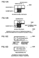
- Figs. 10A to 10D are conceptual diagrams for illustrating another embodiment of the encoding processing for the prediction mode according to the present invention.
- the prediction direction in the target block is estimated by taking advantage of the decoded images in the pre-encoded adjacent blocks A, B, C, and D which are adjacent to the left side, upper-left side, upper side, and upper-right side of the target block (1001).
- the prediction mode whose number is smaller of the prediction modes of the adjacent blocks which are adjacent to the left side and the upper side of the target block respectively is employed as the most probable mode (1002).
- a function g for inputting the edge information on the adjacent blocks A to D and the prediction-mode number p, and calculating the degree of likelihood of the prediction mode p (1003) is taken advantage of, then dynamically creating a variable-length code table based on the degree of likelihood of each prediction mode p. Namely, a shorter code is allocated to the prediction mode whose degree of likelihood is higher, and a longer code is allocated to the prediction mode whose degree of likelihood is lower, thereby making the average code length shorter.
- (1004) the following embodiment is explained: Whether or not the prediction mode in the target block is the same as the most probable mode is represented with 1 bit. Then, if the prediction mode is different from the most probable mode, a variable-length code table with respect to the eight-type prediction modes excluding the most probable mode is created, then performing the encoding based on this variable-length code table. Also, in (1005), the following embodiment is explained: Not depending on whether or not the prediction mode in the target block is the same as the most probable mode, a variable-length code table with respect to all of the nine-type prediction modes is created, then performing the encoding based on this variable-length code table.
- Fig. 11 illustrates an example of the case where the function g is implemented taking advantage of the neural network.
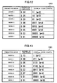
- Fig. 12 and Fig. 13 illustrate examples of the codes (i.e., the variable-length code tables) which will be allocated to each prediction mode when each prediction mode is encoded based on the method indicted in (1005) and taking advantage of the Huffman encoding.
- the most probable mode is the mode 8 is illustrated.
- the 4-bit code is necessary for encoding each prediction mode.
- the present invention is also effective in encoding still-frame pictures. Namely, the portion which remains after excluding the motion search unit (104) and the inter-frame prediction unit (107) from the block diagram illustrated in Fig. 1 is equivalent to the block diagram of an encoding device which is designed specifically for the still-frame pictures.
- the present invention can also be implemented as an image processing (encoding/decoding) system acquired by combining the image encoding device with the image decoding device, or an image processing (encoding/decoding) method acquired by combining the image encoding method with the image decoding method.
Landscapes
- Engineering & Computer Science (AREA)
- Multimedia (AREA)
- Signal Processing (AREA)
- Physics & Mathematics (AREA)
- Theoretical Computer Science (AREA)
- Data Mining & Analysis (AREA)
- General Health & Medical Sciences (AREA)
- Biomedical Technology (AREA)
- Biophysics (AREA)
- Computational Linguistics (AREA)
- Life Sciences & Earth Sciences (AREA)
- Evolutionary Computation (AREA)
- Artificial Intelligence (AREA)
- Molecular Biology (AREA)
- Computing Systems (AREA)
- General Engineering & Computer Science (AREA)
- General Physics & Mathematics (AREA)
- Mathematical Physics (AREA)
- Software Systems (AREA)
- Health & Medical Sciences (AREA)
- Compression Or Coding Systems Of Tv Signals (AREA)
Abstract
Description
- The present invention relates to an image encoding technology for encoding an image such as a moving picture or still-frame picture, and an image decoding technology for decoding the image encoded.
- As techniques for recording and transmitting large-capacity moving-picture information in such a manner that the moving-picture information is converted into digital data, the encoding schemes such as MPEG (: Moving Picture Experts Group) schemes had been formulated, and have become internationally-standardized encoding schemes as MPEG-1 standard, MPEG-2 standard, MPEG-4 standard, and H.264/AVC (: Advanced Video Coding) standard. These schemes are employed in such utilizations as digital satellite broadcasting, DVDs, mobile telephones, and digital cameras. At present, these schemes are becoming more and more expanded in their utilization range, and are becoming increasingly quite familiar to the general public.
- In these standards, an encoding target image is predicted in a block unit by taking advantage of image information whose encoding processing is completed. Then, a prediction difference between the original image and the encoding target image predicted in this way is encoded. By doing this prediction-difference encoding, redundancy which the moving picture possesses is eliminated thereby to reduce the resultant code amount. In H.264/AVC in particular, the intra-frame prediction encoding scheme is employed which takes advantage of peripheral pixels on the periphery of the encoding target block. The employment of this intra-frame prediction encoding scheme has allowed the implementation of a dramatic enhancement in the compression ratio.
- In the above-described intra-frame prediction encoding scheme according to H.264/AVC, one reference pixel is selected from among pixels included in a pre-encoded block. Then, all of the pixels existing along a certain specific prediction direction are predicted using the pixel value of this reference pixel. At this time, the prediction accuracy is enhanced by making the specific prediction direction, which is suitable for the image, selectable from among a plurality of prediction directions defined in advance. In this case, however, a code for representing the prediction direction is required to be added for each block which becomes the prediction unit. Accordingly, there has existed a problem that the code amount increases by the amount equivalent to this addition of the code.
- In, e.g., Jamil-ur-Rehman and Zhang Ye, "Efficient Techniques for Sign alling Intra Prediction Modes of H.264/Mpeg-4 , an attempt to solve this problem has been made. In this technique, the code amount is decreased by shortening the prediction-direction representing code in each of blocks at the frame edges where the prediction-direction number available is comparatively small. This technique, however, can be applied only to the blocks at the frame edges. Consequently, this technique brings about only a small effect of enhancing the compression efficiency.
- Also, in
JP-A-2007-116351 - Moreover, in
JP-A-2004-129260 - In view of the above-described situation, in order to enhance the compression efficiency, there exists a point which should be solved for accomplishing the point of decreasing the code amount for representing a prediction direction with respect to every block within the frame.
- In the present invention, the compression efficiency may be enhanced by decreasing the prediction-direction representing code amount.
- In the present invention, the prediction direction in an encoding target block, i.e., a block which becomes the target of the intra-frame prediction encoding processing, is estimated by taking advantage of pre-encoded blocks which are adjacent to the encoding target block. For example, a Sobel filter is applied to each of decoded images in four pre-encoded blocks which are adjacent to the left side, upper-left side, upper side, and upper-right side of the encoding target block, thereby calculating edge information which includes intensities and angles of the edges. Next, the degree of likelihood of each prediction direction is calculated, using parameters of these eight intensities and angles obtained by this calculation. Finally, the prediction direction whose degree of likelihood is the highest is employed as the prediction direction in the encoding target block. The employment of the prediction direction like this makes it unnecessary to add the prediction-direction representing code to the bit stream.
- The present invention is also effective to direction-independent intra-frame prediction schemes such as, e.g., the DC prediction in H.264/AVC. Accordingly, its application to these schemes makes it possible to expect a significant reduction in the code amount. Also, a variable-length code table is dynamically created based on the above-described estimated result. The creation of this table also allows implementation of a significant reduction in the prediction-direction representing code amount. As a result, it becomes possible to expect an enhancement in the compression efficiency. Incidentally, taking advantage of, e.g., a neural network is effective to the above-described likelihood-degree calculation in each prediction direction.
- According to the present invention, it becomes possible to provide an image encoding technology and decoding technology for offering a high-picture-quality image with a small code amount.
- In the drawings
- These and other features, objects and advantages of the present invention will become more apparent from the following description when taken in conjunction with the accompanying drawings wherein:
-
Fig. 1 is a block diagram for illustrating an embodiment of the image encoding device according to the present invention; -
Fig. 2 is a block diagram for illustrating an embodiment of the image decoding device according to the present invention; -
Fig. 3 is a conceptual explanatory diagram for explaining the intra-frame prediction encoding processing used in H.264/AVC; -
Fig. 4 is a conceptual explanatory diagram for explaining the intra-frame prediction decoding processing used in H.264/AVC; -
Figs. 5A and 5B are conceptual explanatory diagrams for explaining the encoding processing for the prediction mode used in H.264/AVC; -
Figs. 6A and 6B are conceptual explanatory diagrams for explaining an embodiment of the encoding processing for the prediction mode used in the present embodiment; -
Fig. 7 is a conceptual explanatory diagram for explaining an embodiment regarding the likelihood-degree calculation of the prediction mode; -
Fig. 8 is a flowchart in the image encoding device used in the present embodiment; -
Fig. 9 is a flowchart in the image decoding device used in the present embodiment; -
Figs. 10A to 10D are conceptual diagrams for explaining an embodiment of the encoding processing of the prediction mode used in the present embodiment; -
Fig. 11 is a conceptual diagram for explaining an embodiment regarding the likelihood-degree calculation of the prediction mode; -
Fig. 12 is a table for illustrating an example of the variable-length code table; -
Fig. 13 is a table for illustrating another example of the variable-length code table; -
Figs. 14A and 14B are diagrams for illustrating examples of filters used in the edge detection, and; -
Fig. 15 is a conceptual diagram for illustrating an example of the calculation method for the edge information. - While we have shown and described several embodiments in accordance with our invention, it should be understood that disclosed embodiments are susceptible of changes and modifications without departing from the scope of the invention. Therefore, we do not intend to be bound by the details shown and described herein but intend to cover all such changes and modifications a fall within the ambit of the appended claims., as interpreted by the description and drawings. Hereinafter, referring to the drawings, the explanation will be given below concerning embodiments of the present invention.
-
Fig. 3 is a conceptual diagram for explaining the intra-frame prediction encoding processing according to H.264/AVC. In H.264/AVC, the encoding is executed with respect to an encoding target image in accordance with the sequence of the raster scanning (301). Then, the prediction is performed using decoded images in four pre-encoded blocks which are adjacent to the left side, upper-left side, upper side, and upper-right side of the encoding target block. - In particular, for the purpose of the prediction, thirteen decoded pixels included in these four blocks are taken advantage of (302). Of pixels included in the encoding target block, all of the pixels existing on one and the same straight line whose inclination is represented by a prediction-direction vector are predicted from one and the same reference pixel. Namely, the thirteen pixels are the pixels which, of the pixels included in the four blocks, are arranged in a manner of being adjacent to the encoding target block. Concretely, these thirteen pixels are as follows: In the left side block, the four pixels on the right-most longitudinal line; in the upper-left side block, the one pixel at the lower-right corner; and in the upper side and upper-right side blocks, the four pixels arranged transversely on the lower-most side each. Concerning the prediction, if, as indicated by, e.g., (303), the direction of the prediction-direction vector is a downward direction, all of the longitudinally-arranged four pixels B, C, D, and E in the encoding target block are subjected to the prediction encoding by making reference to one and the same reference pixel (i.e., the value A' obtained by decoding the pixel positioned directly above the pixel B) which exists on the prediction-direction vector in the upper side block (here, the prediction for the pixels B, C, D, and E is made by being assumed to be the same value as the value A', namely, each of the predicted pixel values for B, C, D, and E is equal to the value A'). Moreover, with respect to the pixels B, C, D, and E, differences (i.e., prediction differences) b, c, d, and e between the pixels B, C, D, and E and the predicted pixel value A' are calculated.
- In H.264/AVC, not being limited to the above-described downward-direction prediction-direction vector, an optimum prediction-direction vector can be selected in the block unit from among eight types of prediction-direction candidates such as longitudinal, transverse, and oblique prediction directions (i.e., the directions indicated by the arrows of 0, 1, and 3 to 8 in
Fig. 3 ). In H.264/AVC, however, "DC prediction" can also be taken advantage of (304) in addition to the above-described prediction made along the specific prediction direction. In the DC prediction, all of the pixels included in the encoding target block are predicted using an average value of the reference pixels. Theprediction direction 2 is allocated to the DC prediction. Of these prediction methods (which, hereinafter, will be referred to as "prediction modes") that are represented in a manner of being distinguished by the above-described nine types of numbers (i.e., the eight directions + the DC prediction), information for indicating which of the prediction modes has been selected is encoded along with the prediction differences b, c, d, and e. -
Fig. 4 is a conceptual diagram for explaining the intra-frame prediction decoding processing according to H.264/AVC. In the decoding processing as well, as is the case with the encoding processing, the decoding is executed in accordance with the sequence of the raster scanning (401). Then, processing steps which are inverse to the encoding processing are executed, using a pre-decoded reference pixel and prediction differences. Namely, in a decoding target block, in accordance with the prediction mode selected at the time of the encoding processing and along the prediction direction corresponding thereto, the prediction differences (decoded values) are added to the reference pixel, thereby acquiring the decoded image. In, e.g., (402), the following process is indicated: A summation is calculated between prediction differences b', c', d', and e' in the decoding target block (each of which results from decoding each of the prediction differences b, c, d, and e illustrated inFig. 3 , and each of which contains a quantization error) and the reference pixels A'all of which have been pre-decoded, thereby acquiring decoded pixels B', C', D', and E' (each of which is the decoded pixel corresponding to each of B, C, D, and E inFig. 3 ). - As having been described so far, in the intra-frame prediction encoding processing according to H.264/AVC, the single-direction-based prediction encoding method is employed where one reference pixel is specified, and where all of the pixels existing along a specific prediction direction are predicted using the pixel value of this reference pixel. In this case, however, the information for indicating in which direction the prediction will be made has been required to be added for each encoding target block which becomes the unit of the prediction processing.
-
Figs. 5A and 5B illustrate the encoding method for the prediction mode in the intra-frame prediction scheme according to H.264/AVC. In H.264/AVC, attention is focused on the fact that the prediction mode in the encoding target block is highly correlated with the prediction modes in the pre-encoded blocks adjacent thereto. Accordingly, the prediction mode in the encoding target block is predicted from the prediction modes in the pre-encoded adjacent blocks. Namely, as is indicated by (501), reference is made to the prediction mode MA in the adjacent block A which is adjacent to the left side of the encoding target block, and the prediction mode MB in the adjacent block B which is adjacent to the upper side of the encoding target block. Then, the prediction mode whose number (i.e., one of the nine types of numbers illustrated inFig. 3 (Fig. 4 )) is smaller of these two prediction modes MA and MB is employed as the prediction value (most probable mode) of the prediction mode in the encoding target block (502). - The reference numeral (503) in
Fig. 5B illustrates details of the bit configuration which represents the prediction method. In H.264/AVC, if the prediction mode in the encoding target block is the same as the most probable mode, the use of a flag (1 bit) for indicating whether or not the prediction mode is the same as the most probable mode encodes information for indicating that the prediction mode is the same as the most probable mode (i.e., code of "1" as the flag). Meanwhile, if the prediction mode in the encoding target block is different from the most probable mode, the use of the flag encodes information for indicating that the prediction mode is different from the most probable mode (i.e., code of "0" as the flag). After that, the actual prediction mode (of the nine-way prediction modes, one of the eight-way prediction modes excluding the most probable mode) is encoded with 3 bits. In this case, the representation of the prediction mode requires the use of a large amount of code. For example, when the intra-frame prediction is made in the 4-pixel x 4-pixel-size block unit, a 64-bit code occurs at the maximum per macro block. -
Figs. 6A and 6B are conceptual diagrams for illustrating an embodiment of the encoding processing for the prediction mode according to the present invention. Here, as is indicated by (601), the prediction mode in the encoding (decoding) target block is estimated by taking advantage of decoded images in the pre-encoded adjacent blocks A, B, C, and D which are adjacent to the left side, upper-left side, upper side, and upper-right side of the encoding (decoding) target block. The prediction mode in the target block is identified by taking advantage of a function f for inputting edge information on the adjacent blocks A to D, and outputting the prediction mode in the target block (602). Taking advantage of this function f makes it unnecessary to encode the prediction mode. As a result, the bit amount needed for representing the prediction mode becomes equal to zero (603). - Although the type of a detection method for detecting the above-described edge information is not particularly specified, taking advantage of, e.g., a Sobel filter illustrated in
Fig. 14A is quite effective. When taking advantage of the Sobel filter, two types of Sobel filters, i.e., a vertical-direction-use Sobel filter (1401) and a horizontal-direction-use Sobel filter (1402), are used, thereby detecting the edges in the respective directions. Also, the use of a Prewitt filter is allowable. In this case, in addition to a vertical-direction-use filter (1403) and a horizontal-direction-use filter (1404), oblique-direction-use filters (1405) and (1406) are prepared. Also, what is conceivable as a usage example of a simpler filter is the use of a MIN-MAX filter. In the MIN-MAX filter, a rectangular filter in a specific size is prepared at first, then calculating a difference between the maximum value and the minimum value of the concentration value therein. -
Fig. 15 illustrates an example of the calculation method for calculating the edge information including edge intensities and edge angles in the case of taking advantage of the Sobel filters (1401) and (1402). Here, out of the decoded images in the pre-encoded adjacent blocks A, B, C, and D which are adjacent to the left side, upper-left side, upper side, and upper-right side of the encoding (decoding) target block (1501), four pixels (i.e.,pixel 1 to pixel 4) positioned at the center of each of the decoded images are extracted (1503). Then, the vertical-direction-use filter (1401) and the horizontal-direction-use filter (1402) are applied to these four pixels. Assuming that, at this time, values resulting from applying the horizontal-direction-use filter (1402) and the vertical-direction-use filter (1401) to the pixel i (i = 1, ..., 4) are fx (i) and fy (i) receptively, the edge intensity can be calculated as is given by, e.g., (1504), and the edge angles can be calculated as are given by, e.g., (1505) and (1506). - As the function f for outputting the prediction mode in the target block, whatever function is all right. For example, taking advantage of the mechanical learning function of a neural network permits successful implementation of this function f.
Fig. 7 illustrates an example of the case where the function f is implemented taking advantage of the neural network. The neural network refers to a network where a plurality of threshold-value logic units are hierarchically deployed from an input layer to an output layer. In the feed-forward-type network, a connection between the units exists only between layers adjacent to each other, and the connection is a one-direction connection directed from the input layer to the output layer. A weight of the connection is allocated to between the connected units. Moreover, an input into a unit deployed in a higher-order hierarchy becomes equal to a summation of the products of values outputted by a group of units deployed in a lower-order hierarchy and the weights of the connections between the units. When the learning is performed, these weights are adjusted so that a desirable result will be obtained in the output layer. Here, the learning in the neural network (702) is performed in advance so that, when the edge intensities and edge angles of the adjacent blocks A to D are normalized and inputted into the neural network (701), the degree of likelihood of the prediction mode n (n = 0, 1, ..., 8) will be calculated and outputted (703). At this time, a function which will return the prediction-mode number in which the highest degree of likelihood is outputted is set as the above-described function f (704). This setting allows implementation of the encoding and decoding processings based on the method illustrated inFigs. 6A and 6B . Although the learning method to be used for the above-described learning is not particularly specified, taking advantage of, e.g., the BP (: Back Propagation) method permits accomplishment of an outstanding effect. Concerning the BP method, the detailed explanation has been given in, e.g.,Chapter 3 of the following document: - Document: Kenichiro Ishii, Syukou Ueda, Eisaku Maeda, Hiroshi Murase: "Easy-To-Understand Pattern Recognition", Ohm Corp., 1998.
- The candidates for the above-described function f are widely conceivable, ranging from a simple polynomial where the edge intensities and angles are employed as the variable to a function where the mechanical learning techniques are used such as kernel method, SVM (: Support Vector Machine), k-nearest neighbor algorithm, linear determinant analysis, Baysian network, Hidden Markov Model, and decision-tree learning. Also, a plurality of identification devices may be combined by a method of using boosting or the like. With which of the models the function f is to be implemented, or what type of input/output the function f is to perform may be determined by a standard in advance, or it is all right to permit the information on the function f to be stored into the stream. Also, in the above-described embodiment, the edge intensities and angles of the central four pixels in the adjacent blocks are used as the variables. However, whatever information is usable as long as it is information on the peripheral blocks such as pixel-value average, variance, standard deviation, encoding method, and prediction mode of the peripheral blocks. Otherwise, it is all right to add image parameters on the encoding condition such as QP (: Quantization Parameter) and frame resolution.
-
Fig. 1 is a block diagram for illustrating an embodiment of the moving-picture encoding device according to the present invention. The moving-picture encoding device includes an original-image memory (102) for storing original images (101) inputted, a block partition unit (103) for partitioning each of the inputted original images (101) into small regions, a motion search unit (104) for detecting a motion in the block unit, a prediction-mode estimation unit (105) for estimating a prediction direction in the intra-frame prediction, an intra-frame prediction unit (106) for making the intra-frame prediction in the block unit, an inter-frame prediction unit (107) for making an inter-frame prediction in the block unit and based on the motion amount detected by the motion search unit (104), a mode selection unit (108) for determining a prediction encoding scheme (i.e., prediction method and block size) which matches property of the image, a subtraction unit (109) for generating prediction differences, a frequency transformation unit (110) and a quantization processing unit (111) for performing an encoding with respect to the prediction differences, a variable length coding unit (112) for performing a variable length.coding in correspondence with occurrence probability of a code, an inverse quantization processing unit (113) and an inverse frequency transformation unit (114) for decoding the prediction differences encoded once temporarily, an addition unit (115) for generating a decoded image by using the prediction differences decoded, and a reference-image memory (116) for storing the decoded image to take advantage of the decoded image in the prediction later. - The original-image memory (102) stores a piece of image from among the original images (101) as an encoding target image. The block partition unit (103) partitions this encoding target image into small blocks, then transferring these small blocks to the motion search unit (104), the intra-frame prediction unit (106), and the inter-frame prediction unit (107). The motion search unit (104) calculates a motion amount in the blocks by using the pre-decoded image stored in the reference-image memory (116), then transferring the corresponding motion vector to the inter-frame prediction unit (107). The prediction-mode estimation unit (105) extracts, from the reference-image memory (116), decoded images in the pre-encoded blocks positioned on the periphery of the target block, then performing the edge detection to identify the prediction direction in the target block, and transferring the identified prediction direction to the intra-frame prediction unit (106). The intra-frame prediction unit (106) and the inter-frame prediction unit (107) execute the intra-frame prediction processing and the inter-frame prediction processing in the block units in several sizes. The mode selection unit (108) selects an optimum prediction method which is either the intra-frame prediction method or the inter-frame prediction method.
- Subsequently, the subtraction unit (109) generates the prediction differences based on the optimum prediction encoding scheme, then transferring the generated prediction differences to the frequency transformation unit (110). The frequency transformation unit (110) and the quantization processing unit (111) apply a frequency transformation such as the DCT (: Discrete Cosine Transformation) and a quantization processing respectively to the transferred prediction differences in the block unit in a specified size, then transferring the resultant after-quantized frequency transformation coefficients to the variable length coding unit (112) and the inverse quantization processing unit (113). Moreover, based on the occurrence probability of the code, the variable length coding unit (112) performs the variable length coding with respect to the prediction-difference information represented by the after-quantized frequency transformation coefficients, thereby generating an encoded stream. Here, this variable length coding is performed along with the variable length coding of the information needed for the prediction decoding, such as the prediction direction in the intra-frame prediction encoding and the motion vector in the inter-frame prediction encoding. Also, the inverse quantization processing unit (113) and the inverse frequency transformation unit (114) apply an inverse quantization processing and an inverse frequency transformation such as the IDCT (: Inverse DCT) respectively to the after-quantized frequency transformation coefficients, thereby acquiring the prediction differences, and then transferring the acquired prediction differences to the addition unit (115). Subsequently, the addition unit (115) generates the decoded image, which is then stored into the reference-image memory (116). Incidentally, in the prediction-mode estimation unit (105), other than the specific prediction direction, direction-independent intra-frame prediction schemes such as, e.g., the DC prediction in H.264/AVC may also be employed as the target of the estimation.
-
Fig. 2 is a block diagram for illustrating an embodiment of the moving-picture decoding device according to the present invention. The moving-picture decoding device includes, e.g., a variable-length decoding unit (202) for performing an inverse processing step to the variable length coding with respect to the encoded stream (201) which is generated by the moving-picture encoding device illustrated inFig. 1 , an inverse quantization processing unit (203) and an inverse frequency transformation unit (204) for decoding the prediction differences, a prediction-mode estimation unit (205) for estimating a prediction direction in the intra-frame prediction, an intra-frame prediction unit (206) for making the intra-frame prediction, an inter-frame prediction unit (207) for making an inter-frame prediction, an addition unit (208) for acquiring a decoded image, and a reference-image memory (209) for storing the decoded image temporarily. - The variable-length decoding unit (202) performs the variable-length decoding with respect to the encoded stream (201), thereby acquiring the frequency transformation coefficient components of the prediction differences, and the information needed for the prediction processing such as the block size and the motion vector. The former information, i.e., the prediction-difference information is transferred to the inverse quantization processing unit (203). The latter information, i.e., the information needed for the prediction processing is transferred to either the intra-frame prediction unit (206) or the inter-frame prediction unit (207), depending on the prediction scheme. Subsequently, the inverse quantization processing unit (203) and the inverse frequency transformation unit (204) apply the inverse quantization processing and the inverse frequency transformation respectively to the prediction-difference information, thereby performing the decoding. Also, the prediction-mode estimation unit (205) extracts, from the reference-image memory (209), the decoded images in the pre-encoded blocks positioned on the periphery of the target block, then performing the edge detection to identify the prediction direction in the target block, and transferring the identified prediction direction to the intra-frame prediction unit (206). Subsequently, the intra-frame prediction unit (206) or the inter-frame prediction unit (207) executes the prediction processing by making reference to the reference-image memory (209) on the basis of the information transferred from the variable-length decoding unit (202). Moreover, the addition unit (208) generates the decoded image, which is then stored into the reference-image memory (209). In this way, similarly to the moving-picture encoding device, the moving-picture decoding device itself includes the prediction-mode estimation unit (205) and the prediction units (206) and (207) subsequent thereto. As a result, as is the case with the moving-picture encoding device, the prediction processing by which the prediction direction in the target block is identified is executed from the signal decoded from the encoded stream. Consequently, there exists no necessity for adding a prediction-mode representing code to the encoded stream. This feature allows implementation of a reduction in the code amount at the time of encoding and decoding the image.
-
Fig. 8 is a flowchart for illustrating 1-frame encoding processing steps in the embodiment of the moving-picture encoding device illustrated inFig. 1 . First, with respect to all the blocks existing within 1 frame which becomes the encoding target (801), the processing in aloop 1, where each processing up to a processing (814) described hereinafter is repeated, is performed. Within the processing in theloop 1, the processing in aloop 2, where each processing from a processing (803) to a processing (806 or 807) is repeated with respect to all the coding modes, is further performed. Namely, the prediction differences are calculated with respect to the encoding target block by performing the prediction encoding processing with respect to all the coding modes (i.e., combinations of the prediction methods and the block sizes) once temporarily. Then, of all the coding modes, the coding mode which results in the highest encoding efficiency is selected. As the above-described prediction encoding processing method, the intra-frame prediction encoding processing (806) and the inter-frame prediction encoding processing (807) are executed, then selecting an optimum prediction processing method from these processings. This selection allows implementation of a high-efficiency encoding in correspondence with the property of the image. Here, in the case of the intra-frame prediction mode (803), when performing the intra-frame prediction encoding processing (806), the edge included in the pre-encoded blocks positioned on the periphery of the target block is detected using the Sobel filter or the like (804). Moreover, the prediction direction in the target block is identified by taking advantage of, e.g., the function F illustrated in (704) (805). When the coding mode which results in the highest encoding efficiency is selected from among the large number of coding modes (808), taking advantage of, e.g., the RD-Optimization scheme allows implementation of the high-efficiency encoding. In the RD-Optimization scheme, the optimum coding mode is determined from the relationship between image-quality distortion and the code amount. Concerning the details of the RD-Optimization scheme, the description has been given in the following document: -
Document 3; G. Sullivan and T. Wiegand: "Rate-Distortion Optimization for Video Compression", IEEE Signal Processing Magazine, Vol. 15, No. 6, pp. 74 to 90, 1998. - When the processing in the
loop 2 has been terminated, subsequently, the prediction differences generated in the selected optimum coding mode are subjected to the frequency transformation (809) and the quantization processing (810), then being further subjected to the variable length coding thereby to generate the encoded stream (811). Meanwhile, the inverse quantization processing (812) and the inverse frequency transformation (813) are applied to the pre-quantized frequency transformation coefficients, thereby decoding the prediction differences. Furthermore, the decoded image is generated, then being stored into the reference-image memory (814). When the foregoing processings have been terminated with respect to all the blocks, the processing in theloop 1 is terminated. Accordingly, the encoding by the amount of the 1-frame image is terminated (815). -
Fig. 9 is a flowchart for illustrating 1-frame decoding processing steps in the embodiment of the moving-picture decoding device illustrated inFig. 2 . First, with respect to all the blocks existing within 1 frame, the processing in aloop 1, where each processing from a processing (902) to a processing (908 or 909) described hereinafter is repeated, is performed. Namely, the inputted stream is subjected to the variable-length decoding processing (902), then being further subjected to the inverse quantization processing (903) and the inverse frequency transformation (904) thereby to decode the prediction differences. Subsequently, the intra-frame prediction decoding processing (908) or the inter-frame prediction decoding processing (909) is performed depending on by which prediction method the target block has been prediction-encoded. In this way, the decoded image is acquired, then being stored into the reference-image memory. Here, when performing the intra-frame prediction decoding processing (908), the edge included in the pre-decoded blocks positioned on the periphery of the target block is detected using the Sobel filter or the like (906). Moreover, the prediction direction in the target block is identified by taking advantage of, e.g., the function F illustrated in (704) (907). When the foregoing processings have been terminated with respect to all the blocks within the frame, the decoding by the amount of the 1-frame image is terminated as the processing in the loop 1 (910). - In the above-described embodiments, the DCT has been mentioned as an example of the frequency transformation. Whatever transformation method, however, is all right as long as it is an orthogonal transformation used for eliminating the inter-pixel correlation, such as DST (: Discrete Sine Transformation), WT (: Wavelet Transformation), DFT (: Discrete Fourier Transformation), or KLT (: Karhunen-Loeve Transformation). Also, it is allowable to perform the encoding with respect to the prediction differences itself without applying the frequency transformation thereto in particular. Moreover, it is also all right not to perform the variable length coding in particular. In the embodiments, the description has been given regarding the case where the prediction of the luminance component is performed in the 4-pixel x 4-pixel-size block unit in particular. It is also allowable, however, to apply the present invention to a whatever-pixel-size block such as, e.g., 8-pixel x 8-pixel-size block or 16-pixel x 16-pixel-size block, and to apply the present invention to the prediction of a component other than the luminance component such as, e.g., the color-difference component. Also, although, in the embodiments, the prediction along the eight directions stipulated in H.264/AVC has been performed, it is all right to increase or decrease the number of the directions.
-
Figs. 10A to 10D are conceptual diagrams for illustrating another embodiment of the encoding processing for the prediction mode according to the present invention. In the present embodiment as well, as is the case with the embodiment illustrated inFig. 6 , the prediction direction in the target block is estimated by taking advantage of the decoded images in the pre-encoded adjacent blocks A, B, C, and D which are adjacent to the left side, upper-left side, upper side, and upper-right side of the target block (1001). Also, as is the case with H.264/AVC, the prediction mode whose number is smaller of the prediction modes of the adjacent blocks which are adjacent to the left side and the upper side of the target block respectively is employed as the most probable mode (1002). Here, in the present embodiment, a function g for inputting the edge information on the adjacent blocks A to D and the prediction-mode number p, and calculating the degree of likelihood of the prediction mode p (1003) is taken advantage of, then dynamically creating a variable-length code table based on the degree of likelihood of each prediction mode p. Namely, a shorter code is allocated to the prediction mode whose degree of likelihood is higher, and a longer code is allocated to the prediction mode whose degree of likelihood is lower, thereby making the average code length shorter. Although whatever method is all right as the method for creating the variable-length code table, taking advantage of, e.g., Huffman encoding is quite effective. In (1004), the following embodiment is explained: Whether or not the prediction mode in the target block is the same as the most probable mode is represented with 1 bit. Then, if the prediction mode is different from the most probable mode, a variable-length code table with respect to the eight-type prediction modes excluding the most probable mode is created, then performing the encoding based on this variable-length code table. Also, in (1005), the following embodiment is explained: Not depending on whether or not the prediction mode in the target block is the same as the most probable mode, a variable-length code table with respect to all of the nine-type prediction modes is created, then performing the encoding based on this variable-length code table. - Whatever method is all right as the method for implementing the function g for outputting the degree of likelihood of the prediction mode p in the target block. For example, as is the case with the embodiment illustrated in
Fig. 6 , taking advantage of the mechanical learning function of the neural network permits successful implementation of this function g.Fig. 11 illustrates an example of the case where the function g is implemented taking advantage of the neural network. Here as well, as is the case with the neural network illustrated inFig. 7 , the learning in the neural network (1102) is performed in advance so that, when the edge intensities and edge angles of the adjacent blocks A to D are normalized and inputted into the neural network (1002), the degree of likelihood of the prediction mode n (n = 0, 1, ..., 8) will be calculated and outputted (1103). At this time, a function which will output the degree of likelihood of the prediction mode p (p = 0, 1, ..., 8) is set as the above-described function g (1104). This setting allows implementation of the encoding and decoding processings based on the method illustrated inFigs. 10A to 10D . -
Fig. 12 and Fig. 13 illustrate examples of the codes (i.e., the variable-length code tables) which will be allocated to each prediction mode when each prediction mode is encoded based on the method indicted in (1005) and taking advantage of the Huffman encoding. Here, a case where the most probable mode is themode 8 is illustrated. In H.264/AVC, if the prediction mode in the target block is different from the most probable mode, the 4-bit code is necessary for encoding each prediction mode. In contrast thereto, in the example illustrated inFig. 12 , the code amount can be reduced down to 3 bits at the minimum (i.e., 1 bit for representing whether each prediction mode is the same as or different from the most probable mode + 2 bit (i.e., code length m = 2) for representing the number of each prediction mode. Furthermore, if the degree of likelihood of each prediction mode is biased like the example illustrated inFig. 13 , the code amount can be reduced down to 2 bits at the minimum (i.e., 1 bit for representing whether each prediction mode is the same as or different from the most probable mode + 1 bit (i.e., code length m = 1) for representing the number of each prediction mode. In this way, it is preferable to dynamically create the variable-length code table based on the estimated degree of likelihood of each prediction mode. Otherwise, it is all right to create a plurality of variable-length code tables in advance, and to properly use these variable-length code tables depending on the occasions based on the estimated degrees of likelihood. - In the present embodiment, the description has been given concerning the case where the moving pictures are encoded. The present invention, however, is also effective in encoding still-frame pictures. Namely, the portion which remains after excluding the motion search unit (104) and the inter-frame prediction unit (107) from the block diagram illustrated in
Fig. 1 is equivalent to the block diagram of an encoding device which is designed specifically for the still-frame pictures. Also, the present invention can also be implemented as an image processing (encoding/decoding) system acquired by combining the image encoding device with the image decoding device, or an image processing (encoding/decoding) method acquired by combining the image encoding method with the image decoding method. - It should be further understood by those skilled in the art that although the foregoing description has been made on embodiments of the invention, the invention is not limited thereto and various changes and modifications may be made without departing from the spirit of the invention and the scope of the appended claims, as interpreted by the description and drawings.
Claims (14)
- An image encoding device, comprising:an intra-frame prediction encoding unit (106) which calculates prediction differences by performing an intra-frame prediction in a block unit;a prediction-direction estimation unit (105) which estimates a prediction direction in performing said intra-frame prediction;a frequency transformation unit (110) and a quantization processing unit (111) which perform an encoding with respect to said prediction differences; anda variable length coding unit (112) which performs a variable length coding, whereinsaid prediction-direction estimation unit (105) estimates said prediction direction from decoded images in blocks which are adjacent to a block that becomes an encoding target.
- An image encoding method which encodes prediction differences by performing an intra-frame prediction in a block unit,
said image encoding method, comprising a step of:performing said intra-frame prediction along a prediction direction estimated by taking advantage of decoded images in blocks which are adjacent to an encoding target block. - The image encoding method according to Claim 2, further comprising a step of:not encoding said prediction direction estimated in performing said intra-frame prediction.
- The image encoding method according to Claim 2, further comprising the steps of:dynamically creating a variable-length code table based on said prediction direction estimated; andperforming a variable length coding of said prediction direction based on said variable-length code table created.
- The image encoding method according to Claim 2, further comprising the steps of:selecting one prediction direction from among a plurality of variable-length code tables based on said prediction direction estimated, said plurality of variable-length code tables being created in advance; andperforming a variable length coding of said prediction direction selected.
- The image encoding method according to Claim 2, further comprising a step of:estimating said prediction direction based on image parameters such as edge information on said decoded images in said blocks which are adjacent to said encoding target block.
- The image encoding method according to Claim 6, further comprising the steps of:outputting degrees of likelihood of prediction modes by using a neural network (702) which receives an input of said image parameters, and which employs a summation of products as an input into a unit deployed in a higher-order hierarchy of said neural network (702), said products being products of values outputted by a group of units deployed in a lower-order hierarchy of said neural network (702) and weights of connections between said units; andestimating, as said prediction direction, said prediction mode whose degree of likelihood becomes a maximum value.
- An image decoding device, comprising:a variable-length decoding unit (202) which performs an inverse processing step to a variable length coding;an inverse quantization processing unit (203) and an inverse frequency transformation unit (204) which decode prediction differences; andan intra-frame prediction decoding unit (206) which acquires a decoded image by performing an intra-frame prediction, whereinsaid image decoding device further comprises:a prediction-direction estimation unit (205) which estimates a prediction direction in performing said intra-frame prediction by taking advantage of decoded images in blocks which are adjacent to a decoding target block.
- An image decoding method which decodes prediction differences by performing an intra-frame prediction in a block unit,
said image decoding method, comprising a step of:performing said intra-frame prediction along a prediction direction estimated by taking advantage of decoded images in blocks which are adjacent to a decoding target block. - The image decoding method according to Claim 9, further comprising a step of:not decoding said prediction direction estimated in performing said intra-frame prediction.
- The image decoding method according to Claim 9, further comprising the steps of:dynamically creating a variable-length code table based on said prediction direction estimated; andperforming a variable-length decoding of said prediction direction based on said variable-length code table created.
- The image decoding method according to Claim 9, further comprising the steps of:selecting one prediction direction from among a plurality of variable-length code tables based on said prediction direction estimated, said plurality of variable-length code tables being created in advance; andperforming a variable-length decoding of said prediction direction selected.
- The image decoding method according to Claim 9, further comprising a step of:estimating said prediction direction based on image parameters such as edge information on said decoded images in said blocks which are adjacent to said decoding target block.
- The image decoding method according to Claim 13, further comprising the steps of:outputting degrees of likelihood of prediction modes by using a neural network (702) which receives an input of said image parameters, and which employs a summation of products as an input into a unit deployed in a higher-order hierarchy of said neural network (702), said products being products of values outputted by a group of units deployed in a lower-order hierarchy of said neural network (702) and weights of connections between said units; andestimating, as said prediction direction, said prediction mode whose degree of likelihood becomes a maximum value.
Applications Claiming Priority (1)
| Application Number | Priority Date | Filing Date | Title |
|---|---|---|---|
| JP2007281605A JP2009111691A (en) | 2007-10-30 | 2007-10-30 | Image encoding apparatus, encoding method, image decoding apparatus, and decoding method |
Publications (2)
| Publication Number | Publication Date |
|---|---|
| EP2063644A2 true EP2063644A2 (en) | 2009-05-27 |
| EP2063644A3 EP2063644A3 (en) | 2009-09-30 |
Family
ID=40512581
Family Applications (1)
| Application Number | Title | Priority Date | Filing Date |
|---|---|---|---|
| EP20080253486 Withdrawn EP2063644A3 (en) | 2007-10-30 | 2008-10-27 | Image encoding device and encoding method, and image decoding device and decoding method |
Country Status (4)
| Country | Link |
|---|---|
| US (1) | US20090110070A1 (en) |
| EP (1) | EP2063644A3 (en) |
| JP (1) | JP2009111691A (en) |
| CN (1) | CN101426141A (en) |
Cited By (7)
| Publication number | Priority date | Publication date | Assignee | Title |
|---|---|---|---|---|
| EP2391130A3 (en) * | 2010-05-30 | 2012-02-15 | LG Electronics Inc. | Enhanced intra mode signaling |
| US9270992B2 (en) | 2011-01-13 | 2016-02-23 | Canon Kabushiki Kaisha | Image coding apparatus, image coding method and program, image decoding apparatus, and image decoding method and program |
| EP3032830A1 (en) * | 2014-12-08 | 2016-06-15 | Thomson Licensing | Differential coding of intra modes |
| WO2018002474A1 (en) * | 2016-06-29 | 2018-01-04 | B<>Com | Method for intra-coding of a digital image and corresponding decoding method |
| WO2018099579A1 (en) * | 2016-12-02 | 2018-06-07 | Huawei Technologies Co., Ltd. | Apparatus and method for encoding an image |
| WO2019072921A1 (en) * | 2017-10-13 | 2019-04-18 | Fraunhofer-Gesellschaft zur Förderung der angewandten Forschung e.V. | Intra-prediction mode concept for block-wise picture coding |
| US11694125B2 (en) | 2017-10-19 | 2023-07-04 | Samsung Electronics Co., Ltd. | Image encoder using machine learning and data processing method of the image encoder |
Families Citing this family (71)
| Publication number | Priority date | Publication date | Assignee | Title |
|---|---|---|---|---|
| WO2013067667A1 (en) | 2011-11-07 | 2013-05-16 | Intel Corporation | Cross-channel residual prediction |
| US20090180701A1 (en) * | 2008-01-10 | 2009-07-16 | Seungyeob Choi | Video Data Encoding System |
| JP5166339B2 (en) * | 2008-03-28 | 2013-03-21 | 三星電子株式会社 | Method and apparatus for encoding and / or decoding intra prediction mode information of image |
| TWI386068B (en) * | 2008-10-22 | 2013-02-11 | Nippon Telegraph & Telephone | Deblocking processing method, deblocking processing device, deblocking processing program and computer readable storage medium in which the program is stored |
| WO2010087157A1 (en) * | 2009-01-29 | 2010-08-05 | パナソニック株式会社 | Image coding method and image decoding method |
| JP5586101B2 (en) | 2009-03-23 | 2014-09-10 | 株式会社Nttドコモ | Image predictive encoding device, image predictive encoding method, image predictive encoding program, image predictive decoding device, image predictive decoding method, and image predictive decoding program |
| KR101527085B1 (en) * | 2009-06-30 | 2015-06-10 | 한국전자통신연구원 | Intra encoding/decoding method and apparautus |
| JP5416277B2 (en) * | 2009-07-10 | 2014-02-12 | サムスン エレクトロニクス カンパニー リミテッド | Spatial prediction method and apparatus in hierarchical video coding |
| KR101474756B1 (en) | 2009-08-13 | 2014-12-19 | 삼성전자주식회사 | Method and apparatus for encoding and decoding image using large transform unit |
| JP5746182B2 (en) * | 2009-09-14 | 2015-07-08 | トムソン ライセンシングThomson Licensing | Efficient video encoding and decoding method and apparatus for intra prediction mode |
| US9819952B2 (en) * | 2009-10-05 | 2017-11-14 | Thomson Licensing Dtv | Methods and apparatus for embedded quantization parameter adjustment in video encoding and decoding |
| JP2011151682A (en) * | 2010-01-22 | 2011-08-04 | Sony Corp | Image processing apparatus and method |
| WO2011104993A1 (en) * | 2010-02-24 | 2011-09-01 | シャープ株式会社 | Image encoding device, image decoding device, and data structure |
| JP5222878B2 (en) * | 2010-03-24 | 2013-06-26 | 日本放送協会 | Intra prediction apparatus, encoder, decoder, and program |
| US20110274169A1 (en) * | 2010-05-05 | 2011-11-10 | Paz Adar | Device, system, and method for spatially encoding video data |
| US8559512B2 (en) | 2010-05-05 | 2013-10-15 | Ceva D.S.P. Ltd. | Device, system, and method for predicting residual data for intra and inter frame encoding of image or video data |
| US9131236B2 (en) | 2010-05-12 | 2015-09-08 | Nippon Telegraph And Telephone Corporation | Code amount control method and apparatus |
| RU2580073C2 (en) * | 2010-07-15 | 2016-04-10 | Мицубиси Электрик Корпорейшн | Device for coding of moving images, device for decoding of moving images, method for coding of moving images and method for decoding of moving images |
| PH12013500092A1 (en) * | 2010-07-15 | 2017-05-05 | Velos Media Int Ltd | Image intra-prediction mode estimation device, image encoding device, image decoding device, and encoded image data |
| KR101770662B1 (en) | 2010-07-20 | 2017-08-23 | 가부시키가이샤 엔.티.티.도코모 | Image prediction decoding device and image prediction decoding method |
| WO2012043766A1 (en) * | 2010-09-29 | 2012-04-05 | シャープ株式会社 | Image decoding device, image encoding device, and data structure for encoded data |
| WO2012043676A1 (en) * | 2010-09-29 | 2012-04-05 | シャープ株式会社 | Decoding device, encoding device, and data structure |
| WO2012043678A1 (en) * | 2010-09-30 | 2012-04-05 | シャープ株式会社 | Image decoding device, image encoding device, and data structure |
| US8885704B2 (en) | 2010-10-01 | 2014-11-11 | Qualcomm Incorporated | Coding prediction modes in video coding |
| JPWO2012090413A1 (en) | 2010-12-27 | 2014-06-05 | 日本電気株式会社 | Video encoding apparatus, video decoding apparatus, video encoding method, video decoding method, and program |
| US9490839B2 (en) | 2011-01-03 | 2016-11-08 | Qualcomm Incorporated | Variable length coding of video block coefficients |
| EP4557737A3 (en) | 2011-01-07 | 2025-08-06 | LG Electronics Inc. | Method for encoding and decoding image information and device using same |
| WO2012134046A2 (en) * | 2011-04-01 | 2012-10-04 | 주식회사 아이벡스피티홀딩스 | Method for encoding video |
| ES2459890B2 (en) * | 2011-04-25 | 2015-06-05 | Lg Electronics Inc. | Intra prediction method, and encoder and decoder that use it |
| HUE067788T2 (en) | 2011-04-25 | 2024-11-28 | Lg Electronics Inc | Intra-prediction method for video decoding and video encoding |
| GB2491391B (en) * | 2011-06-02 | 2014-09-03 | Canon Kk | Encoding mode values representing prediction modes |
| US9654785B2 (en) | 2011-06-09 | 2017-05-16 | Qualcomm Incorporated | Enhanced intra-prediction mode signaling for video coding using neighboring mode |
| RU2660640C1 (en) * | 2011-06-28 | 2018-07-06 | Самсунг Электроникс Ко., Лтд. | Method and device for coding video, and also method and device for decoding video supported by internal prediction |
| US9516316B2 (en) | 2011-06-29 | 2016-12-06 | Qualcomm Incorporated | VLC coefficient coding for large chroma block |
| US9338456B2 (en) | 2011-07-11 | 2016-05-10 | Qualcomm Incorporated | Coding syntax elements using VLC codewords |
| EP2736254B1 (en) * | 2011-07-22 | 2018-07-04 | Hitachi, Ltd. | Video decoding method and image encoding method |
| CN103931193B (en) * | 2011-09-21 | 2017-11-21 | Lg电子株式会社 | The method and apparatus of encoding/decoding image |
| KR101762294B1 (en) * | 2011-10-18 | 2017-07-28 | 주식회사 케이티 | Method for encoding image, method for decoding image, image encoder, and image decoder |
| CN103096060B (en) * | 2011-11-08 | 2017-03-29 | 乐金电子(中国)研究开发中心有限公司 | The adaptive loop filter method and device of intra-frame image prediction encoding and decoding |
| US20160132754A1 (en) * | 2012-05-25 | 2016-05-12 | The Johns Hopkins University | Integrated real-time tracking system for normal and anomaly tracking and the methods therefor |
| US9532080B2 (en) | 2012-05-31 | 2016-12-27 | Sonic Ip, Inc. | Systems and methods for the reuse of encoding information in encoding alternative streams of video data |
| US9374592B2 (en) * | 2012-09-08 | 2016-06-21 | Texas Instruments Incorporated | Mode estimation in pipelined architectures |
| US9357210B2 (en) | 2013-02-28 | 2016-05-31 | Sonic Ip, Inc. | Systems and methods of encoding multiple video streams for adaptive bitrate streaming |
| WO2015133320A1 (en) * | 2014-03-05 | 2015-09-11 | ソニー株式会社 | Image coding device and method |
| JP6381996B2 (en) * | 2014-06-30 | 2018-08-29 | キヤノンメディカルシステムズ株式会社 | Medical image processing apparatus and X-ray CT apparatus |
| JP6052319B2 (en) * | 2015-03-25 | 2016-12-27 | Nttエレクトロニクス株式会社 | Video encoding device |
| WO2016197317A1 (en) * | 2015-06-09 | 2016-12-15 | 富士通株式会社 | Copy information encoding and decoding method and apparatus, and image processing device |
| CN107736027B (en) * | 2015-06-12 | 2021-06-01 | 松下知识产权经营株式会社 | Image encoding method, image decoding method, image encoding device, and image decoding device |
| JP2017099616A (en) * | 2015-12-01 | 2017-06-08 | ソニー株式会社 | Surgical control device, surgical control method and program, and surgical system |
| KR101974261B1 (en) * | 2016-06-24 | 2019-04-30 | 한국과학기술원 | Encoding method and apparatus comprising convolutional neural network(cnn) based in-loop filter, and decoding method and apparatus comprising convolutional neural network(cnn) based in-loop filter |
| US10623775B1 (en) * | 2016-11-04 | 2020-04-14 | Twitter, Inc. | End-to-end video and image compression |
| GB2574733B (en) * | 2016-12-28 | 2020-05-06 | Arris Entpr Llc | Improved video bitstream coding |
| JP2018125718A (en) * | 2017-02-01 | 2018-08-09 | 日本放送協会 | Mode prediction information generation device and program |
| WO2018199051A1 (en) | 2017-04-25 | 2018-11-01 | パナソニック インテレクチュアル プロパティ コーポレーション オブ アメリカ | Coding device, decoding device, coding method, and decoding method |
| US11197013B2 (en) | 2017-07-06 | 2021-12-07 | Samsung Electronics Co., Ltd. | Method and device for encoding or decoding image |
| JP2019041165A (en) * | 2017-08-23 | 2019-03-14 | 富士通株式会社 | Image encoding device, image decoding device, image processing method, and image processing program |
| EP3451670A1 (en) * | 2017-08-28 | 2019-03-06 | Thomson Licensing | Method and apparatus for filtering with mode-aware deep learning |
| CN108289224B (en) * | 2017-12-12 | 2019-10-29 | 北京大学 | A kind of video frame prediction technique, device and neural network is compensated automatically |
| US10687054B2 (en) * | 2017-12-20 | 2020-06-16 | Intel Corporation | Decoupled prediction and coding structure for video encoding |
| JP6992825B2 (en) | 2018-01-30 | 2022-01-13 | 富士通株式会社 | Video coding device, video coding method, video decoding device, video decoding method, and video coding system |
| EP3562162A1 (en) | 2018-04-27 | 2019-10-30 | InterDigital VC Holdings, Inc. | Method and apparatus for video encoding and decoding based on neural network implementation of cabac |
| US10499081B1 (en) * | 2018-06-19 | 2019-12-03 | Sony Interactive Entertainment Inc. | Neural network powered codec |
| US11474978B2 (en) | 2018-07-06 | 2022-10-18 | Capital One Services, Llc | Systems and methods for a data search engine based on data profiles |
| US10635939B2 (en) | 2018-07-06 | 2020-04-28 | Capital One Services, Llc | System, method, and computer-accessible medium for evaluating multi-dimensional synthetic data using integrated variants analysis |
| JP6940006B2 (en) * | 2018-08-08 | 2021-09-22 | 富士通株式会社 | Coding device, coding method, coding program, decoding device, decoding method and decoding program |
| CN111131829B (en) * | 2018-10-31 | 2021-12-24 | 联发科技股份有限公司 | Video encoding apparatus and method |
| US11601644B2 (en) * | 2018-12-11 | 2023-03-07 | Google Llc | Image and video coding using machine learning prediction coding models |
| CN111641831B (en) * | 2019-03-01 | 2023-09-01 | 杭州海康威视数字技术股份有限公司 | Intra prediction method, device, equipment and storage medium |
| US11068665B2 (en) * | 2019-09-18 | 2021-07-20 | International Business Machines Corporation | Hypernym detection using strict partial order networks |
| US11876988B2 (en) * | 2021-01-19 | 2024-01-16 | Tencent America LLC | Method and apparatus for task-adaptive pre-processing for neural image compression |
| FR3120173A1 (en) * | 2021-02-19 | 2022-08-26 | Orange | Determining at least one picture encoding mode or at least one picture decoding mode, picture encoding and decoding using such determination |
Citations (2)
| Publication number | Priority date | Publication date | Assignee | Title |
|---|---|---|---|---|
| JP2004129260A (en) | 2002-09-30 | 2004-04-22 | Samsung Electronics Co Ltd | Video coding and decoding method and apparatus using spatial prediction coding of hue |
| JP2007116351A (en) | 2005-10-19 | 2007-05-10 | Ntt Docomo Inc | Image predictive encoding device, image predictive decoding device, image predictive encoding method, image predictive decoding method, image predictive encoding program, and image predictive decoding program |
Family Cites Families (5)
| Publication number | Priority date | Publication date | Assignee | Title |
|---|---|---|---|---|
| FR2681750A1 (en) * | 1991-09-20 | 1993-03-26 | Thomson Csf | METHOD FOR COMPRESSING IMAGES |
| JP4542447B2 (en) * | 2005-02-18 | 2010-09-15 | 株式会社日立製作所 | Image encoding / decoding device, encoding / decoding program, and encoding / decoding method |
| US20080123947A1 (en) * | 2005-07-22 | 2008-05-29 | Mitsubishi Electric Corporation | Image encoding device, image decoding device, image encoding method, image decoding method, image encoding program, image decoding program, computer readable recording medium having image encoding program recorded therein |
| CA2610276C (en) * | 2005-07-22 | 2013-01-29 | Mitsubishi Electric Corporation | Image encoder and image decoder, image encoding method and image decoding method, image encoding program and image decoding program, and computer readable recording medium recorded with image encoding program and computer readable recording medium recorded with image decoding program |
| JP4769605B2 (en) * | 2006-03-17 | 2011-09-07 | 富士通株式会社 | Video coding apparatus and method |
-
2007
- 2007-10-30 JP JP2007281605A patent/JP2009111691A/en active Pending
-
2008
- 2008-10-27 EP EP20080253486 patent/EP2063644A3/en not_active Withdrawn
- 2008-10-29 CN CNA2008101730561A patent/CN101426141A/en active Pending
- 2008-10-29 US US12/260,332 patent/US20090110070A1/en not_active Abandoned
Patent Citations (2)
| Publication number | Priority date | Publication date | Assignee | Title |
|---|---|---|---|---|
| JP2004129260A (en) | 2002-09-30 | 2004-04-22 | Samsung Electronics Co Ltd | Video coding and decoding method and apparatus using spatial prediction coding of hue |
| JP2007116351A (en) | 2005-10-19 | 2007-05-10 | Ntt Docomo Inc | Image predictive encoding device, image predictive decoding device, image predictive encoding method, image predictive decoding method, image predictive encoding program, and image predictive decoding program |
Non-Patent Citations (4)
| Title |
|---|
| G. SULLIVAN; T. WIEGAND: "Rate-Distortion Optimization for Video Compression", IEEE SIGNAL PROCESSING MAGAZINE, vol. 15, no. 6, 1998, pages 74 - 90, XP011089821, DOI: doi:10.1109/79.733497 |
| SYUKOU UEDA; EISAKU MAEDA; HIROSHI MURASE: "Easy-To-Understand Pattern Recognition", 1998, OHM CORP. |
| ZHANG YE: "Efficient Techniques for Sign alling Intra Prediction Modes of H.264/Mpeg-4 Part 10", PROC. ICICIC2006, August 2006 (2006-08-01) |
| ZHONG XUE ET AL: "An Automatic Mode Decision Method for Intra Frame Coding and Decoding", ITU STUDY GROUP 16 - VIDEO CODING EXPERTS GROUP -ISO/IEC MPEG & ITU-T VCEG(ISO/IEC JTC1/SC29/WG11 AND ITU-T SG16 Q6), XX, XX, no. M7719, 26 November 2001 (2001-11-26), XP030036810 * |
Cited By (21)
| Publication number | Priority date | Publication date | Assignee | Title |
|---|---|---|---|---|
| US11297331B2 (en) | 2010-05-30 | 2022-04-05 | Lg Electronics Inc. | Enhanced intra prediction mode signaling |
| US10390023B2 (en) | 2010-05-30 | 2019-08-20 | Lg Electronics Inc. | Enhanced intra prediction mode signaling |
| US9398303B2 (en) | 2010-05-30 | 2016-07-19 | Lg Electronics Inc. | Enhanced intra prediction mode signaling |
| US10742997B2 (en) | 2010-05-30 | 2020-08-11 | Lg Electronics Inc. | Enhanced intra prediction mode signaling |
| US11800117B2 (en) | 2010-05-30 | 2023-10-24 | Lg Electronics Inc. | Enhanced intra prediction mode signaling |
| EP2391130A3 (en) * | 2010-05-30 | 2012-02-15 | LG Electronics Inc. | Enhanced intra mode signaling |
| US10034003B2 (en) | 2010-05-30 | 2018-07-24 | Lg Electronics Inc. | Enhanced intra prediction mode signaling |
| US8902978B2 (en) | 2010-05-30 | 2014-12-02 | Lg Electronics Inc. | Enhanced intra prediction mode signaling |
| US9270992B2 (en) | 2011-01-13 | 2016-02-23 | Canon Kabushiki Kaisha | Image coding apparatus, image coding method and program, image decoding apparatus, and image decoding method and program |
| EP3032830A1 (en) * | 2014-12-08 | 2016-06-15 | Thomson Licensing | Differential coding of intra modes |
| WO2016091727A1 (en) * | 2014-12-08 | 2016-06-16 | Thomson Licensing | Coding of intra modes |
| WO2018002474A1 (en) * | 2016-06-29 | 2018-01-04 | B<>Com | Method for intra-coding of a digital image and corresponding decoding method |
| US10812814B2 (en) | 2016-06-29 | 2020-10-20 | B<>Com | Method for intra-coding of a digital image and corresponding decoding method |
| FR3053555A1 (en) * | 2016-06-29 | 2018-01-05 | B<>Com | METHOD FOR ENCODING A DIGITAL IMAGE, DECODING METHOD, DEVICES, TERMINAL AND COMPUTER PROGRAMS |
| WO2018099579A1 (en) * | 2016-12-02 | 2018-06-07 | Huawei Technologies Co., Ltd. | Apparatus and method for encoding an image |
| WO2019072921A1 (en) * | 2017-10-13 | 2019-04-18 | Fraunhofer-Gesellschaft zur Förderung der angewandten Forschung e.V. | Intra-prediction mode concept for block-wise picture coding |
| TWI702824B (en) * | 2017-10-13 | 2020-08-21 | 弗勞恩霍夫爾協會 | Intra-prediction mode concept for block-wise picture coding |
| US11363259B2 (en) | 2017-10-13 | 2022-06-14 | Fraunhofer-Gesellschaft Zur Förderung Der Angewandten Forschung E.V., München | Intra-prediction mode concept for block-wise picture coding |
| TWI794623B (en) * | 2017-10-13 | 2023-03-01 | 弗勞恩霍夫爾協會 | Intra-prediction mode concept for block-wise picture coding |
| US11889066B2 (en) | 2017-10-13 | 2024-01-30 | Fraunhofer-Gesellschaft zur Förderung der angewandten Forschung e.V. | Intra-prediction mode concept for block-wise picture coding |
| US11694125B2 (en) | 2017-10-19 | 2023-07-04 | Samsung Electronics Co., Ltd. | Image encoder using machine learning and data processing method of the image encoder |
Also Published As
| Publication number | Publication date |
|---|---|
| JP2009111691A (en) | 2009-05-21 |
| EP2063644A3 (en) | 2009-09-30 |
| CN101426141A (en) | 2009-05-06 |
| US20090110070A1 (en) | 2009-04-30 |
Similar Documents
| Publication | Publication Date | Title |
|---|---|---|
| EP2063644A2 (en) | Image encoding device and encoding method, and image decoding device and decoding method | |
| US11838509B2 (en) | Video coding method and apparatus | |
| US9058659B2 (en) | Methods and apparatuses for encoding/decoding high resolution images | |
| RU2509436C1 (en) | Method and apparatus for encoding and decoding coding unit of picture boundary | |
| KR101228020B1 (en) | Video coding method and apparatus using side matching, and video decoding method and appartus thereof | |
| CN107241605B (en) | Video encoder and video encoding method | |
| US10645410B2 (en) | Video decoding apparatus | |
| US8285064B2 (en) | Method for processing images and the corresponding electronic device | |
| CN109429071B (en) | Image encoding device, image decoding device and image processing method | |
| KR20080110171A (en) | Method and apparatus for intra prediction coding and decoding using image reconstruction | |
| JP7507913B2 (en) | Method for encoding and decoding an image, encoding and decoding device and corresponding computer program product | |
| US20090028241A1 (en) | Device and method of coding moving image and device and method of decoding moving image | |
| JP2025520260A (en) | Method, apparatus and system for encoding and decoding tensors | |
| JP2025532752A (en) | Method, apparatus and system for encoding and decoding tensors | |
| WO2025227394A1 (en) | System and method for unified reference picture synthesis | |
| JP7664750B2 (en) | Encoding device, program, and model generation method | |
| WO2025148775A1 (en) | Method and apparatus for intra prediction area in video coding | |
| KR101603412B1 (en) | Method and apparatus for encoding of video using depth image |
Legal Events
| Date | Code | Title | Description |
|---|---|---|---|
| PUAI | Public reference made under article 153(3) epc to a published international application that has entered the european phase |
Free format text: ORIGINAL CODE: 0009012 |
|
| 17P | Request for examination filed |
Effective date: 20081114 |
|
| AK | Designated contracting states |
Kind code of ref document: A2 Designated state(s): AT BE BG CH CY CZ DE DK EE ES FI FR GB GR HR HU IE IS IT LI LT LU LV MC MT NL NO PL PT RO SE SI SK TR |
|
| AX | Request for extension of the european patent |
Extension state: AL BA MK RS |
|
| PUAL | Search report despatched |
Free format text: ORIGINAL CODE: 0009013 |
|
| AK | Designated contracting states |
Kind code of ref document: A3 Designated state(s): AT BE BG CH CY CZ DE DK EE ES FI FR GB GR HR HU IE IS IT LI LT LU LV MC MT NL NO PL PT RO SE SI SK TR |
|
| AX | Request for extension of the european patent |
Extension state: AL BA MK RS |
|
| 17Q | First examination report despatched |
Effective date: 20091202 |
|
| AKX | Designation fees paid |
Designated state(s): AT BE BG CH CY CZ DE DK EE ES FI FR GB GR HR HU IE IS IT LI LT LU LV MC MT NL NO PL PT RO SE SI SK TR |
|
| STAA | Information on the status of an ep patent application or granted ep patent |
Free format text: STATUS: THE APPLICATION IS DEEMED TO BE WITHDRAWN |
|
| 18D | Application deemed to be withdrawn |
Effective date: 20110114 |