EP2063554A2 - Method and system for ordering sequences for synchronization signaling in a wireless system - Google Patents
Method and system for ordering sequences for synchronization signaling in a wireless system Download PDFInfo
- Publication number
- EP2063554A2 EP2063554A2 EP08019962A EP08019962A EP2063554A2 EP 2063554 A2 EP2063554 A2 EP 2063554A2 EP 08019962 A EP08019962 A EP 08019962A EP 08019962 A EP08019962 A EP 08019962A EP 2063554 A2 EP2063554 A2 EP 2063554A2
- Authority
- EP
- European Patent Office
- Prior art keywords
- sequences
- sequence
- synchronization
- sss
- length
- Prior art date
- Legal status (The legal status is an assumption and is not a legal conclusion. Google has not performed a legal analysis and makes no representation as to the accuracy of the status listed.)
- Withdrawn
Links
- 238000000034 method Methods 0.000 title claims abstract description 32
- 230000011664 signaling Effects 0.000 title abstract description 11
- 238000012545 processing Methods 0.000 claims abstract description 7
- 239000011159 matrix material Substances 0.000 abstract description 18
- 125000004122 cyclic group Chemical group 0.000 description 12
- 238000004891 communication Methods 0.000 description 6
- 238000001514 detection method Methods 0.000 description 6
- 238000010586 diagram Methods 0.000 description 6
- 238000004590 computer program Methods 0.000 description 4
- 238000013459 approach Methods 0.000 description 3
- 230000008901 benefit Effects 0.000 description 3
- 239000000463 material Substances 0.000 description 2
- 230000005540 biological transmission Effects 0.000 description 1
- 230000001413 cellular effect Effects 0.000 description 1
- 238000006243 chemical reaction Methods 0.000 description 1
- 230000006870 function Effects 0.000 description 1
- 238000010348 incorporation Methods 0.000 description 1
- 230000010365 information processing Effects 0.000 description 1
- 230000007774 longterm Effects 0.000 description 1
- 238000012423 maintenance Methods 0.000 description 1
- 238000010295 mobile communication Methods 0.000 description 1
- 238000012986 modification Methods 0.000 description 1
- 230000004048 modification Effects 0.000 description 1
Images


Classifications
-
- H—ELECTRICITY
- H04—ELECTRIC COMMUNICATION TECHNIQUE
- H04W—WIRELESS COMMUNICATION NETWORKS
- H04W56/00—Synchronisation arrangements
- H04W56/0055—Synchronisation arrangements determining timing error of reception due to propagation delay
- H04W56/0065—Synchronisation arrangements determining timing error of reception due to propagation delay using measurement of signal travel time
- H04W56/007—Open loop measurement
- H04W56/0075—Open loop measurement based on arrival time vs. expected arrival time
- H04W56/0085—Open loop measurement based on arrival time vs. expected arrival time detecting a given structure in the signal
-
- H—ELECTRICITY
- H04—ELECTRIC COMMUNICATION TECHNIQUE
- H04B—TRANSMISSION
- H04B2201/00—Indexing scheme relating to details of transmission systems not covered by a single group of H04B3/00 - H04B13/00
- H04B2201/69—Orthogonal indexing scheme relating to spread spectrum techniques in general
- H04B2201/707—Orthogonal indexing scheme relating to spread spectrum techniques in general relating to direct sequence modulation
- H04B2201/70718—Particular systems or standards
- H04B2201/70724—UMTS
-
- H—ELECTRICITY
- H04—ELECTRIC COMMUNICATION TECHNIQUE
- H04L—TRANSMISSION OF DIGITAL INFORMATION, e.g. TELEGRAPHIC COMMUNICATION
- H04L7/00—Arrangements for synchronising receiver with transmitter
- H04L7/04—Speed or phase control by synchronisation signals
- H04L7/041—Speed or phase control by synchronisation signals using special codes as synchronising signal
- H04L7/042—Detectors therefor, e.g. correlators, state machines
Definitions
- Certain embodiments of the invention relate to wireless communication systems. More specifically, certain embodiments of the invention relate to a method and system for ordering sequences for synchronization signaling in a wireless system.
- Mobile communications have changed the way people communicate and mobile device users have come to depend on high quality cellular service to conduct business and stay in contact.
- a mobile device Before negotiating service with a serving base station, a mobile device needs to acquire certain cell-specific information transmitted from base stations, for example, for time and/or frequency synchronization.
- the cell-specific information is carried by the reference and/or synchronization signals.
- the latter forms the basis for downlink synchronization and cell ID information identification at the mobile device.
- Two downlink (DL) synchronization signals namely Primary Synchronization Signal (PSS) and Secondary Synchronization Signal (SSS), are defined and these are used to carry timing information to the mobile device so that the mobile device may obtain the correct timing for the DL frames. These signals are also used to convey base station identity information.
- PSS Primary Synchronization Signal
- SSS Secondary Synchronization Signal
- a system and/or method is provided for ordering sequences for synchronization signaling in a wireless system, substantially as shown in and/or described in connection with at least one of the figures, as set forth more completely in the claims.
- a method for processing signals comprises:
- said synchronization sequence is constructed from one or more maximal length sequence (m-sequence).
- said base station is a eUTRAN base station.
- the method further comprises calculating correlations between said received signal and said ordered set of maximal length sequences.
- the method further comprises determining said synchronization sequence based on said calculated correlations.
- said ordered set of maximal length sequences is transformed from a single maximal length sequence (m-sequence) in a determined order.
- the method further comprises generating a subsequent m-sequence of said ordered set of maximal length sequences by successive left cyclic shift of said generated first m-sequence.
- the method further comprises generating a Walsh-Hadamard matrix based on said ordered set of maximal length sequences.
- the method further comprises determining said synchronization sequence based on said Walsh-Hadamard matrix.
- said ordered set of maximal length sequences forms a Walsh-Hadamard matrix.
- a system for signal processing comprises:
- said synchronization sequence is constructed from one or more maximal length sequence.
- said base station is a eUTRAN base station.
- said one or more circuits are operable to calculate correlations between said received signal and said ordered set of maximal length sequences.
- said one or more circuits are operable to determine said synchronization sequence based on said calculated correlations.
- said ordered set of maximal length sequences is transformed from a single maximal length sequence (m-sequence) in a determined order.
- said one or more circuits are operable to generate a subsequent m-sequence of said ordered set of maximal length sequences by successive left cyclic shift of said generated first m-sequence.
- said one or more circuits are operable to generate a Walsh-Hadamard matrix based on said ordered set of maximal length sequences.
- said one or more circuits are operable to determine said synchronization sequence based on said Walsh-Hadamard matrix.
- said ordered set of maximal length sequences forms a Walsh-Hadamard matrix.
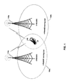
- FIG.1 is a diagram illustrating an exemplary EUTRA (LTE) communication system that may utilize ordered sequences for synchronization signaling, in accordance with an embodiment of the invention.
- LTE EUTRA
- FIG. 2 is a block diagram of an exemplary EUTRA (LTE) downlink synchronization signal structure, in accordance with an embodiment of the invention.
- LTE EUTRA
- FIG. 3 is a diagram illustrating an m-sequence generator that may be utilized for generating ordered m-sequences for synchronization signaling, in accordance with an embodiment of the invention.
- FIG. 4 is a flow chart illustrating exemplary steps for generating m-sequences, in accordance with an embodiment of the invention.
- a user equipment may be operable to receive signals from one or more eUTRAN base stations (NodeBs).
- the received signals may comprise binary synchronization sequences transmitted utilizing synchronization signals such as a secondary synchronization signal (SSS).
- the UE may be enabled to determine the received primary synchronization and secondary synchronization signals for downlink synchronization by correlating the received signal with possible candidates for PSS sequence and SSS sequences, respectively.
- An SSS sequence may be constructed by concatenating and interleaving two m-sequences from an ordered set of m-sequences.
- the UE may take an m-sequence transform approach to determine which sequence from the ordered set of m-sequences may be received.
- the subsequent m-sequences in the ordered set of m-sequences may be generated by successive left cyclic shift of the generated first m-sequence.
- the ordered set of m-sequences may form a 2 n ⁇ 2 n Walsh-Hadamard matrix.
- the UE may use a fast Walsh-Hadamard matrix transform in the secondary synchronization signal (SSS) detection
- FIG. 1 is a diagram illustrating an exemplary EUTRA (LTE) communication system that may utilize ordered sequences for synchronization signaling, in accordance with an embodiment of the invention.
- a eUTRAN base station (e-NodeB1) 110a a eUTRAN base station (e-NodeB2) 110b, an e-NodeB1 serving cell 120a, an e-NodeB2 serving cell 120b, and a user equipment (UE) 130.
- e-NodeB1 eUTRAN base station
- e-NodeB2 e-NodeB2 serving cell 120b
- UE user equipment
- a eUTRAN base station such as the e-NodeB1 110a and/or the e-NodeB2 110b may comprise suitable logic, circuitry and/or code that may enable establishment, maintenance and termination of connections over the EUTRA (LTE) air interface.
- the e-NodeB1 110a and/or the e-NodeB2 110b may be operable to manage radio resources such as, for example, radio bearer control, radio admission control, connection mobility control, and dynamic allocation of resources for the UE 130 in both uplink and downlink (scheduling).
- the eUTRAN base station such as the e-NodeB1 110a may be configured to transmit synchronization sequences to the UE 130 using the downlink synchronization signals such as the primary synchronization signal (PSS) and the secondary synchronization signal (SSS) in one or more radio frames.
- the UE 130 may acquire time and frequency synchronization with the e-NodeB1 serving cell 120a and may determine the Cell ID of the e-NodeB1 serving cell 120a based on the received PSS and SSS.
- the e-NodeB1 110a may be enabled to assign and control a plurality of communications parameters such as, for example, physical layer cell ID group and physical layer ID, which may be utilized by the UEs to acquire, for example, slot and frame timing of the downlink transmission.
- a plurality of communications parameters such as, for example, physical layer cell ID group and physical layer ID, which may be utilized by the UEs to acquire, for example, slot and frame timing of the downlink transmission.
- the UE 130 may comprise suitable logic, circuitry and/or code that may be enabled to communicate with an eUTRAN base station such as the e-NodeB1 110a.
- the UE 130 may be enabled to establish, maintain, and/or terminate communications with the e-NodeB1 110a by performing various procedures such as link set-up and cell search. For example, in instances when the UE 130 may be switched on and/or during active or idle modes, the UE 130 may perform cell search to acquire slot and frame timing, as well as frequency synchronization with a base station.
- the UE 130 may also be enabled to detect the cell ID of the cell, and obtain system parameters such as cyclic prefix (CP) length and system bandwidth.
- CP cyclic prefix
- the UE 130 may be enabled to establish synchronization with the transmitter based on the correlation of the received signal with a set of PSS time-domain sequences and SSS sequences.
- a SSS sequence may be constructed by concatenating and interleaving two m-sequences.
- the two m-sequences may be from an ordered set of m-sequences, which may be obtained by initializing the m-sequence generator with a specific initialization sequence.
- the usage of the ordered set of m-sequences may enable the UE 130 to reduce the computational complexity in SSS detection via using an m-sequence transform technique based on, for example, the fast Walsh-Hadamard transform.
- the UE 130 may receive signals from eUTRAN base stations such as the e-NodeB1 110a and/or the e-NodeB2, respectively.
- the UE 130 may perform cell search to achieve time and frequency synchronization of the UE 130 with a base station such as the e-NodeB1 serving cell 120a or the e-NodeB2 serving cell 120b.
- the UE 130 may acquire slot synchronization to the cell via a plurality of filters matched to the set of PSS sequences that could be contained in the received signal.
- the UE 130 may identify the SSS sequence transmitted from the e-NodeB1 110a and/or the e-NodeB2 by correlating the received signal with possible SSS sequences formed from an ordered set of m-sequences.
- the UE 130 may achieve frame synchronization and determine the cell ID information based on the identified PSS and SSS sequences.
- the UE 130 may camp on the determined cell for communication with the corresponding serving base station, either the e-NodeB1 110a or the e-NodeB2, accordingly.
- FIG. 2 is a block diagram of an exemplary EUTRA (LTE) downlink frame structure, in accordance with an embodiment of the invention.
- LTE EUTRA
- the downlink radio frame 200 may be divided into twenty equally sized slots with two contiguous slots arranged into a sub-frame such as the sub-frame 210.
- Each sub-frame such as the sub-frame 210 may comprise two equally sized slots.
- the downlink synchronization signals such as PSS 210a and SSS 210b may be transmitted from an eUTRAN base station such as, for example, the e-NodeB1 110a and/or the e-NodeB2 110b, to the UE 130 so that the UE 130 may obtain correct timing for the downlink radio frame 200 and acquire the correct cell ID.
- the PSS 210a and SSS 210b may be transmitted on sub-frame 0 and 5 of the downlink radio frame 200 and occupy two consecutive OFDM symbols in a corresponding sub-frame.
- the PSS may be used to identify the symbol timing and the physical cell ID within a cell ID group while the SSS may be used for identifying frame boundary, detecting cell ID group, system parameters such as CP length.
- the UE 130 may correlate the received signal with possible SSS sequences in order to detect the transmitted SSS sequence from the eUTRAN base station such as, for example, the e-NodeB1 110a and/or the e-NodeB2 110b.
- the possible SSS sequences may be constructed by m-sequences from an ordered set of m-sequences to achieve a lower computational complexity in SSS processing.
- FIG. 3 is a diagram illustrating an exemplary m-sequence generator that may be utilized for generating ordered m-sequences for synchronization signaling, in accordance with an embodiment of the invention.
- an m-sequence generator 300 comprising an Ex-OR 310 and a plurality of shift register stages or cells (SR), of which SR1 301 a, SR2 301 b, SR3 301 c, SR4 301 d, and SR5 301 e are illustrated.
- SR shift register stages or cells
- the m-sequence generator 300 may comprise suitable logic, circuitry and/or code that may enable generating binary sequences such as the maximum length sequences or m-sequences.
- the 2 n -1 m-sequences of length 2 n -1 may be generated by cyclically shifting any one m-sequence within the set by 1,2,..., 2 n -2, respectively. In most instances, therefore, the 2 n -1 m-sequences of length 2 n -1 may be made equivalent to each other by a suitable cyclic bit shift.
- the set of 2 n -1 m-sequences of length2 n -1 which corresponds to various cyclic shifts or phases of a single m-sequence, may be transformed to a Walsh-Hadamard matrix of size 2 n ⁇ 2 n , such that a fast Walsh-Hadamard matrix transform may be applied to reduce computational complexity for SSS processing at the receiver.
- Various ways may be utilized to generate the set of 2 n - 1 desired m-sequences of length 2 n -1, and these ways may vary based on, for example, an initial setting of the generator polynomial and a specific form of a n ,a n -1 ,...,a 1 ⁇ [0,1].
- the second desirable m-sequence of length 2 n -1 in the set may be obtained by one-bit left cyclic shift of the first desirable m-sequence of length 2 n -1.
- the third desirable m-sequence of length 2 n -1 in the set may be generated by one-bit left cyclic shift of the second desirable m-sequence of length 2 n -1, and so on.
- the process may continue in a way that further desired m-sequences of length 2 n -1 in the set may be generated from successive one-bit left cyclic shifts of the first desirable m-sequence of length 2 n -1.
- the k th m-sequence, where 1 ⁇ k ⁇ 2 n -1, in the set of the desired m-sequences of length 2 n -1 may be generated by k successive one-bit left cyclic shifts of the first desirable m-sequence of length 2" -1.
- the m-sequence generator 300 may comprise, for example, 5 exemplary shift registers stages or cells, indicated by SR1 301a, SR2 301b, SR3 301c, SR4 301d, and SR5 301e, respectively.
- These 5 exemplary shift registers may be operable to generate a complete set of 2 5 -1 m-sequences of length 2 5 -1 by way of linear feedback shift registers (LFSR) via the Ex-OR 320.
- the Ex-OR 320 may comprise suitable logic, circuitry and/or code that may enable performing XOR operation over inputs from, for example, SR3 301b and SR5 301 e, respectively.
- the Ex-OR 320 may provide a feedback to the m-sequence generator 300, for example, to the SR1 301 a.
- the m-sequence generator 300 may produce the complete set of 2 5 -1 different but cyclically identical m-sequences of length 2 5 -1.
- the m-sequence generator 300 may be enabled to generate 2 5 -1 desired m-sequences of length 2 5 -1, which may form a 32x32 Walsh-Hadamard matrix after pre-pending a zero to every sequence, in a determined order.
- the generated first desired m-sequence of length 2 5 -1 is: [0000100101100111110001101110101].
- the second desired m-sequence of length 2 5 -1 may be generated as: [0001001011001111100011011101010].
- the third desired m-sequence of length 2 5 -1 may be generated as: [0010010110011111000110111010100]. The process may go on until the complete set of desired m-sequences of length 2 5 -1 may be generated as presented in Table 1.
- Table 1 may provide a size of 32x32 Walsh-Hadamard matrix by, for example, pre-pending to each sequence a 0 and re-ordering the sequence elements, which may enable various algorithms such as a fast Walsh-Hadamard matrix transform for SSS sequence detection.
- the 2 5 -1 m-sequences of length 2 5 -1 may each be a cyclically left shifted version of the first m-sequence of length 2 5 -1.
- the generated set of 2 5 -1 m-sequences of length 2 5 -1 may form a 32x32 Walsh-Hadamard matrix that may permit the use of the fast Walsh-Hadamard transform at the UE 130 to achieve a lower computational complexity in correlation operations for SSS detection.
- FIG. 4 is a flow chart illustrating exemplary steps for generating m-sequences, in accordance with an embodiment of the invention.
- the m-sequence index k may be compared with 2 n -1 to determine whether the complete set of 2 n -1 m-sequences of length 2 n -1 has been generated. In instances where k may be less than 2 n -1, then in step 408, the m-sequence index k may be incremented by 1.
- the k th m-sequence may be generated by k bits successive cyclical left shifting of the first m-sequence.
- the k th m-sequence may be generated by 1-bit cyclical left shifting of the ( k -1) th m-sequence.
- the process may return to the step 406.
- step 406 in instances where k may be equal to or greater than 2 n -1, this may indicate that the complete set of 2 n -1 m-sequences of length 2 n -1 have been generated.
- the process may be ended in step 412.
- the UE 130 may receive signals from a base station such as the e-NodeB 1 110a.
- the received signals may be transmitted in a format, which may comprise synchronization signals PSS 210a and SSS 210b, respectively.
- Synchronization sequences may be carried by the PSS 210 and the SSS 210b for downlink signal synchronization at the UE 130.
- a PSS sequence may be used for slot synchronization and physical layer cell ID identification within a cell ID group
- an SSS sequence may be used for frame synchronization and in conjunction with PSS, cell ID group detection.
- the UE 130 may determine the PSS sequence and the SSS sequence by correlating the received signals with possible candidates for PSS sequences and SSS sequences.
- An SSS sequence may be constructed by concatenating and interleaving two m-sequences from an ordered set of m-sequences provided by the m-sequence generator 300.
- the UE 130 may take an m-sequence transform approach to determine which sequence from the ordered set of m-sequences may be received.
- the subsequent m-sequences of the particular set of m-sequences may be generated by successive cyclical left shifting of the generated first m-sequence.
- the ordered set of m-sequences generated may form a Walsh-Hadamard matrix such like, for example, after pre-pending a 0 to each sequence and re-ordering the resulted sequences as presented in Table 1, a fast Walsh-Hadamard matrix transform may be used for SSS sequence detection.
- Another embodiment of the invention may provide a machine and/or computer readable storage and/or medium, having stored thereon, a machine code and/or a computer program having at least one code section executable by a machine and/or a computer, thereby causing the machine and/or computer to perform the steps as described herein for a method and system for ordering sequences for synchronization signaling in a wireless system.
- the present invention may be realized in hardware, software, or a combination of hardware and software.
- the present invention may be realized in a centralized fashion in at least one computer system, or in a distributed fashion where different elements are spread across several interconnected computer systems. Any kind of computer system or other apparatus adapted for carrying out the methods described herein is suited.
- a typical combination of hardware and software may be a general-purpose computer system with a computer program that, when being loaded and executed, controls the computer system such that it carries out the methods described herein.
- the present invention may also be embedded in a computer program product, which comprises all the features enabling the implementation of the methods described herein, and which when loaded in a computer system is able to carry out these methods.
- Computer program in the present context means any expression, in any language, code or notation, of a set of instructions intended to cause a system having an information processing capability to perform a particular function either directly or after either or both of the following: a) conversion to another language, code or notation; b) reproduction in a different material form.
Landscapes
- Engineering & Computer Science (AREA)
- Computer Networks & Wireless Communication (AREA)
- Signal Processing (AREA)
- Mobile Radio Communication Systems (AREA)
Abstract
Description
- This patent application makes reference to, claims priority to and claims benefit from United States Provisional Patent Application Serial No.
60/990,218 filed on November 26, 2007 - This patent application also makes reference to, claims priority to and claims benefit from United States Provisional Patent Application Serial No
61/095,454 filed on September 09, 2008 - Each of the above state applications is hereby incorporated herein by reference in its entirety.
- Certain embodiments of the invention relate to wireless communication systems. More specifically, certain embodiments of the invention relate to a method and system for ordering sequences for synchronization signaling in a wireless system.
- Mobile communications have changed the way people communicate and mobile device users have come to depend on high quality cellular service to conduct business and stay in contact. Before negotiating service with a serving base station, a mobile device needs to acquire certain cell-specific information transmitted from base stations, for example, for time and/or frequency synchronization.
- In 3GPP EUTRA or Long Term Evolution (LTE), the cell-specific information is carried by the reference and/or synchronization signals. The latter forms the basis for downlink synchronization and cell ID information identification at the mobile device. Two downlink (DL) synchronization signals, namely Primary Synchronization Signal (PSS) and Secondary Synchronization Signal (SSS), are defined and these are used to carry timing information to the mobile device so that the mobile device may obtain the correct timing for the DL frames. These signals are also used to convey base station identity information.
- Further limitations and disadvantages of conventional and traditional approaches will become apparent to one of skill in the art, through comparison of such systems with some aspects of the present invention as set forth in the remainder of the present application with reference to the drawings.
- A system and/or method is provided for ordering sequences for synchronization signaling in a wireless system, substantially as shown in and/or described in connection with at least one of the figures, as set forth more completely in the claims.
- According to an aspect, a method for processing signals comprises:
- receiving, at a user equipment (UE), a signal comprising a synchronization sequence from a base station; and
- determining said synchronization sequence based on an ordered set of maximal length sequences (m-sequences) at said UE.
- Advantageously, said synchronization sequence is constructed from one or more maximal length sequence (m-sequence).
- Advantageously, said base station is a eUTRAN base station.
- Advantageously, the method further comprises calculating correlations between said received signal and said ordered set of maximal length sequences.
- Advantageously, the method further comprises determining said synchronization sequence based on said calculated correlations.
- Advantageously, said ordered set of maximal length sequences is transformed from a single maximal length sequence (m-sequence) in a determined order.
- Advantageously, the method further comprises generating a first m-sequence of said ordered set of maximal length sequences from an initial setting of [SR 1,SR 2,...,SRn ]=[1,0,...,0] of an n-stage m-sequence generator, where 2 n -1 equals to the length of said received synchronization sequence, where n is an non-zero integer.
- Advantageously, the method further comprises generating a subsequent m-sequence of said ordered set of maximal length sequences by successive left cyclic shift of said generated first m-sequence.
- Advantageously, the method further comprises generating a Walsh-Hadamard matrix based on said ordered set of maximal length sequences.
- Advantageously, the method further comprises determining said synchronization sequence based on said Walsh-Hadamard matrix.
- Advantageously, said ordered set of maximal length sequences forms a Walsh-Hadamard matrix.
- According to an aspect, a system for signal processing comprises:
- one or more circuits operable to receive, at a user equipment (UE), a signal comprising a synchronization sequence from a base station; and
- said one or more circuits operable to determine said synchronization sequence based on an ordered set of maximal length sequences (m-sequences) at said UE.
- Advantageously, said synchronization sequence is constructed from one or more maximal length sequence.
- Advantageously, said base station is a eUTRAN base station.
- Advantageously, said one or more circuits are operable to calculate correlations between said received signal and said ordered set of maximal length sequences.
- Advantageously, said one or more circuits are operable to determine said synchronization sequence based on said calculated correlations.
- Advantageously, said ordered set of maximal length sequences is transformed from a single maximal length sequence (m-sequence) in a determined order.
- Advantageously, said one or more circuits are operable to generate a first m-sequence of said ordered set of maximal length sequences from an initial setting of [SR 1 , SR 2,...,SRn ]= [1,0,...,0] of an n-stage m-sequence generator, where 2 n-1 equals to the length of said received synchronization sequence, where n is non-zero integer.
- Advantageously, said one or more circuits are operable to generate a subsequent m-sequence of said ordered set of maximal length sequences by successive left cyclic shift of said generated first m-sequence.
- Advantageously, said one or more circuits are operable to generate a Walsh-Hadamard matrix based on said ordered set of maximal length sequences.
- Advantageously, said one or more circuits are operable to determine said synchronization sequence based on said Walsh-Hadamard matrix.
- Advantageously, said ordered set of maximal length sequences forms a Walsh-Hadamard matrix.
- These and other advantages, aspects and novel features of the present invention, as well as details of an illustrated embodiment thereof, will be more fully understood from the following description and drawings.
-
FIG.1 is a diagram illustrating an exemplary EUTRA (LTE) communication system that may utilize ordered sequences for synchronization signaling, in accordance with an embodiment of the invention. -
FIG. 2 is a block diagram of an exemplary EUTRA (LTE) downlink synchronization signal structure, in accordance with an embodiment of the invention. -
FIG. 3 is a diagram illustrating an m-sequence generator that may be utilized for generating ordered m-sequences for synchronization signaling, in accordance with an embodiment of the invention. -
FIG. 4 is a flow chart illustrating exemplary steps for generating m-sequences, in accordance with an embodiment of the invention. - Certain embodiments of the invention may be found in a method and system for ordering sequences for synchronization signaling in a wireless system. In accordance with various aspects of the invention, a user equipment (UE) may be operable to receive signals from one or more eUTRAN base stations (NodeBs). The received signals may comprise binary synchronization sequences transmitted utilizing synchronization signals such as a secondary synchronization signal (SSS). The UE may be enabled to determine the received primary synchronization and secondary synchronization signals for downlink synchronization by correlating the received signal with possible candidates for PSS sequence and SSS sequences, respectively. An SSS sequence may be constructed by concatenating and interleaving two m-sequences from an ordered set of m-sequences. The UE may take an m-sequence transform approach to determine which sequence from the ordered set of m-sequences may be received. The first m-sequence of the ordered set may be obtained by setting initial contents of shift register[SR 1, SR 2,...,SRn ] of corresponding m-sequence generator as follows:

where n is the order of the m-sequence generator. The subsequent m-sequences in the ordered set of m-sequences may be generated by successive left cyclic shift of the generated first m-sequence. The ordered set of m-sequences may form a 2 n × 2 n Walsh-Hadamard matrix. The UE may use a fast Walsh-Hadamard matrix transform in the secondary synchronization signal (SSS) detection. -
FIG. 1 is a diagram illustrating an exemplary EUTRA (LTE) communication system that may utilize ordered sequences for synchronization signaling, in accordance with an embodiment of the invention. Referring toFIG. 1 , there is shown a eUTRAN base station (e-NodeB1) 110a, a eUTRAN base station (e-NodeB2) 110b, an e-NodeB1 servingcell 120a, an e-NodeB2 servingcell 120b, and a user equipment (UE) 130. - A eUTRAN base station such as the
e-NodeB1 110a and/or thee-NodeB2 110b may comprise suitable logic, circuitry and/or code that may enable establishment, maintenance and termination of connections over the EUTRA (LTE) air interface. Thee-NodeB1 110a and/or the e-NodeB2 110b may be operable to manage radio resources such as, for example, radio bearer control, radio admission control, connection mobility control, and dynamic allocation of resources for theUE 130 in both uplink and downlink (scheduling). In this regard, the eUTRAN base station such as thee-NodeB1 110a may be configured to transmit synchronization sequences to theUE 130 using the downlink synchronization signals such as the primary synchronization signal (PSS) and the secondary synchronization signal (SSS) in one or more radio frames. TheUE 130 may acquire time and frequency synchronization with thee-NodeB1 serving cell 120a and may determine the Cell ID of thee-NodeB1 serving cell 120a based on the received PSS and SSS. Thee-NodeB1 110a may be enabled to assign and control a plurality of communications parameters such as, for example, physical layer cell ID group and physical layer ID, which may be utilized by the UEs to acquire, for example, slot and frame timing of the downlink transmission. - The
UE 130 may comprise suitable logic, circuitry and/or code that may be enabled to communicate with an eUTRAN base station such as thee-NodeB1 110a. TheUE 130 may be enabled to establish, maintain, and/or terminate communications with thee-NodeB1 110a by performing various procedures such as link set-up and cell search. For example, in instances when theUE 130 may be switched on and/or during active or idle modes, theUE 130 may perform cell search to acquire slot and frame timing, as well as frequency synchronization with a base station. TheUE 130 may also be enabled to detect the cell ID of the cell, and obtain system parameters such as cyclic prefix (CP) length and system bandwidth. TheUE 130 may be enabled to establish synchronization with the transmitter based on the correlation of the received signal with a set of PSS time-domain sequences and SSS sequences. - A SSS sequence may be constructed by concatenating and interleaving two m-sequences. In this regard, the two m-sequences may be from an ordered set of m-sequences, which may be obtained by initializing the m-sequence generator with a specific initialization sequence. The usage of the ordered set of m-sequences may enable the
UE 130 to reduce the computational complexity in SSS detection via using an m-sequence transform technique based on, for example, the fast Walsh-Hadamard transform. - In operation, the
UE 130 may receive signals from eUTRAN base stations such as thee-NodeB1 110a and/or the e-NodeB2, respectively. TheUE 130 may perform cell search to achieve time and frequency synchronization of theUE 130 with a base station such as thee-NodeB1 serving cell 120a or thee-NodeB2 serving cell 120b. During the cell search, theUE 130 may acquire slot synchronization to the cell via a plurality of filters matched to the set of PSS sequences that could be contained in the received signal. TheUE 130 may identify the SSS sequence transmitted from thee-NodeB1 110a and/or the e-NodeB2 by correlating the received signal with possible SSS sequences formed from an ordered set of m-sequences. TheUE 130 may achieve frame synchronization and determine the cell ID information based on the identified PSS and SSS sequences. TheUE 130 may camp on the determined cell for communication with the corresponding serving base station, either the e-NodeB1 110a or the e-NodeB2, accordingly. -
FIG. 2 is a block diagram of an exemplary EUTRA (LTE) downlink frame structure, in accordance with an embodiment of the invention. Referring toFIG. 2 , there is shown adownlink radio frame 200. In EUTRA (LTE), thedownlink radio frame 200 may be divided into twenty equally sized slots with two contiguous slots arranged into a sub-frame such as thesub-frame 210. Each sub-frame such as thesub-frame 210 may comprise two equally sized slots. The downlink synchronization signals such asPSS 210a andSSS 210b may be transmitted from an eUTRAN base station such as, for example, thee-NodeB1 110a and/or the e-NodeB2 110b, to theUE 130 so that theUE 130 may obtain correct timing for thedownlink radio frame 200 and acquire the correct cell ID. ThePSS 210a andSSS 210b may be transmitted onsub-frame downlink radio frame 200 and occupy two consecutive OFDM symbols in a corresponding sub-frame. The PSS may be used to identify the symbol timing and the physical cell ID within a cell ID group while the SSS may be used for identifying frame boundary, detecting cell ID group, system parameters such as CP length. TheUE 130 may correlate the received signal with possible SSS sequences in order to detect the transmitted SSS sequence from the eUTRAN base station such as, for example, thee-NodeB1 110a and/or the e-NodeB2 110b. In this regard, the possible SSS sequences may be constructed by m-sequences from an ordered set of m-sequences to achieve a lower computational complexity in SSS processing. -
FIG. 3 is a diagram illustrating an exemplary m-sequence generator that may be utilized for generating ordered m-sequences for synchronization signaling, in accordance with an embodiment of the invention. Referring toFIG. 3 , there is shown an m-sequence generator 300 comprising an Ex-OR 310 and a plurality of shift register stages or cells (SR), of which SR1 301 a,SR2 301 b, SR3 301 c, SR4 301 d, and SR5 301 e are illustrated. - The m-
sequence generator 300 may comprise suitable logic, circuitry and/or code that may enable generating binary sequences such as the maximum length sequences or m-sequences. In general, a set of 2 n -1 m-sequences of length 2n-1 may be generated by a generator polynomial of g(X)=anXn +a n-1 X n-1+...+a 1 X+1, where n is the order of the generator polynomial, and an,a n-1 ,...,a 1 ∈ [0,1] are coefficients of the generator polynomial. The 2 n -1 m-sequences of length 2 n -1 may be generated by cyclically shifting any one m-sequence within the set by 1,2,..., 2n -2, respectively. In most instances, therefore, the 2 n -1 m-sequences of length 2 n -1 may be made equivalent to each other by a suitable cyclic bit shift. In this regard, the set of 2 n -1 m-sequences of length2 n -1, which corresponds to various cyclic shifts or phases of a single m-sequence, may be transformed to a Walsh-Hadamard matrix ofsize 2n × 2 n , such that a fast Walsh-Hadamard matrix transform may be applied to reduce computational complexity for SSS processing at the receiver. Various ways may be utilized to generate the set of 2 n-1 desired m-sequences of length 2 n -1, and these ways may vary based on, for example, an initial setting of the generator polynomial and a specific form of an,a n-1 ,...,a 1 ∈[0,1]. In this regard, the set of 2 n -1 desired m-sequences of length 2 n -1 may be generated in a determined order with the initial setting of [SR 1, SR 2 ,..., SR n]= [1,0,...,0]. - In accordance with an embodiment of the invention, the first desirable m-sequence of length 2 n -1 in the set may be generated by initializing the contents of n shift register stages or cells of corresponding m-sequence generator with [SR 1, SR 2,..., SR n ]=[1,0,...,0]. The second desirable m-sequence of length 2 n -1 in the set may be obtained by one-bit left cyclic shift of the first desirable m-sequence of length 2 n -1. The third desirable m-sequence of length 2 n -1 in the set may be generated by one-bit left cyclic shift of the second desirable m-sequence of length 2 n -1, and so on. The process may continue in a way that further desired m-sequences of length 2 n -1 in the set may be generated from successive one-bit left cyclic shifts of the first desirable m-sequence of length 2n -1. For example, the kth m-sequence, where 1 < k≤ 2n -1, in the set of the desired m-sequences of length 2n -1 may be generated by k successive one-bit left cyclic shifts of the first desirable m-sequence of
length 2" -1. - The m-
sequence generator 300 may represent a realization of a generator polynomial of g(X)=X 5+X 2+1, where n = 5 and [a 5,a 4,..., a 0]=[1,0,0,1,0,1]. The generator polynomial of g(X)=X 5+X 2+1 may be used for generating the SSS sequences defined in 3GPP EUTRA (LTE). The m-sequence generator 300 may comprise, for example, 5 exemplary shift registers stages or cells, indicated bySR1 301a,SR2 301b,SR3 301c,SR4 301d, andSR5 301e, respectively. These 5 exemplary shift registers may be operable to generate a complete set of 25-1 m-sequences of length 25-1 by way of linear feedback shift registers (LFSR) via the Ex-OR 320. The Ex-OR 320 may comprise suitable logic, circuitry and/or code that may enable performing XOR operation over inputs from, for example,SR3 301b and SR5 301 e, respectively. The Ex-OR 320 may provide a feedback to the m-sequence generator 300, for example, to the SR1 301 a. The m-sequence generator 300 may produce the complete set of 25-1 different but cyclically identical m-sequences of length 25-1. In this regard, the m-sequence generator 300 may be enabled to generate 25-1 desired m-sequences of length 25-1, which may form a 32x32 Walsh-Hadamard matrix after pre-pending a zero to every sequence, in a determined order. - In accordance with an embodiment of the invention, the first desired m-sequence of length 25-1 may be generated by setting the contents of the 5 shift registers of the m-
sequence generator 300 as [SR 1,SR 2,...,SR 5]=[1,0,...,0]. The generated first desired m-sequence of length 25-1 is:
[0000100101100111110001101110101].
By one-bit left cyclic shift of the first desired m-sequence of length 25-1, the second desired m-sequence of length 25-1 may be generated as:
[0001001011001111100011011101010].
By one-bit left cyclic shift of the second desired m-sequence of length 25-1, the third desired m-sequence of length 25-1 may be generated as:
[0010010110011111000110111010100].
The process may go on until the complete set of desired m-sequences of length 25-1 may be generated as presented in Table 1. Table 1 may provide a size of 32x32 Walsh-Hadamard matrix by, for example, pre-pending to each sequence a 0 and re-ordering the sequence elements, which may enable various algorithms such as a fast Walsh-Hadamard matrix transform for SSS sequence detection.Table 1 Set of desired m-sequences for g(X) = X 5 +X 2 +1 Seq # Sequence 0 0 0 0 0 1 0 0 1 0 1 1 0 0 1 1 1 1 1 0 0 0 1 1 0 1 1 1 0 1 0 1 1 0 0 0 1 0 0 1 0 1 1 0 0 1 1 1 1 1 0 0 0 1 1 0 1 1 1 0 1 0 1 0 2 0 0 1 0 0 1 0 1 1 0 0 1 1 1 1 1 0 0 0 1 1 0 1 1 1 0 1 0 1 0 0 3 0 1 0 0 1 0 1 1 0 0 1 1 1 1 1 0 0 0 1 1 0 1 1 1 0 1 0 1 0 0 0 4 1 0 0 1 0 1 1 0 0 1 1 1 1 1 0 0 0 1 1 0 1 1 1 0 1 0 1 0 0 0 0 5 0 0 1 0 1 1 0 0 1 1 1 1 1 0 0 0 1 1 0 1 1 1 0 1 0 1 0 0 0 0 1 6 0 1 0 1 1 0 0 1 1 1 1 1 0 0 0 1 1 0 1 1 1 0 1 0 1 0 0 0 0 1 0 7 1 0 1 1 0 0 1 1 1 1 1 0 0 0 1 1 0 1 1 1 0 1 0 1 0 0 0 0 1 0 0 8 0 1 1 0 0 1 1 1 1 1 0 0 0 1 1 0 1 1 1 0 1 0 1 0 0 0 0 1 0 0 1 9 1 1 0 0 1 1 1 1 1 0 0 0 1 1 0 1 1 1 0 1 0 1 0 0 0 0 1 0 0 1 0 10 1 0 0 1 1 1 1 1 0 0 0 1 1 0 1 1 1 0 1 0 1 0 0 0 0 1 0 0 1 0 1 11 0 0 1 1 1 1 1 0 0 0 1 1 0 1 1 1 0 1 0 1 0 0 0 0 1 0 0 1 0 1 1 12 0 1 1 1 1 1 0 0 0 1 1 0 1 1 1 0 1 0 1 0 0 0 0 1 0 0 1 0 1 1 0 13 1 1 1 1 1 0 0 0 1 1 0 1 1 1 0 1 0 1 0 0 0 0 1 0 0 1 0 1 1 0 0 14 1 1 1 1 0 0 0 1 1 0 1 1 1 0 1 0 1 0 0 0 0 1 0 0 1 0 1 1 0 0 1 15 1 1 1 0 0 0 1 1 0 1 1 1 0 1 0 1 0 0 0 0 1 0 0 1 0 1 1 0 0 1 1 16 1 1 0 0 0 1 1 0 1 1 1 0 1 0 1 0 0 0 0 1 0 0 1 0 1 1 0 0 1 1 1 17 1 0 0 0 1 1 0 1 1 1 0 1 0 1 0 0 0 0 1 0 0 1 0 1 1 0 0 1 1 1 1 18 0 0 0 1 1 0 1 1 1 0 1 0 1 0 0 0 0 1 0 0 1 0 1 1 0 0 1 1 1 1 1 19 0 0 1 1 0 1 1 1 0 1 0 1 0 0 0 0 1 0 0 1 0 1 1 0 0 1 1 1 1 1 0 20 0 1 1 0 1 1 1 0 1 0 1 0 0 0 0 1 0 0 1 0 1 1 0 0 1 1 1 1 1 0 0 21 1 1 0 1 1 1 0 1 0 1 0 0 0 0 1 0 0 1 0 1 1 0 0 1 1 1 1 1 0 0 0 22 1 0 1 1 1 0 1 0 1 0 0 0 0 1 0 0 1 0 1 1 0 0 1 1 1 1 1 0 0 0 1 23 0 1 1 1 0 1 0 1 0 0 0 0 1 0 0 1 0 1 1 0 0 1 1 1 1 1 0 0 0 1 1 24 1 1 1 0 1 0 1 0 0 0 0 1 0 0 1 0 1 1 0 0 1 1 1 1 1 0 0 0 1 1 0 25 1 1 0 1 0 1 0 0 0 0 1 0 0 1 0 1 1 0 0 1 1 1 1 1 0 0 0 1 1 0 1 26 1 0 1 0 1 0 0 0 0 1 0 0 1 0 1 1 0 0 1 1 1 1 1 0 0 0 1 1 0 1 1 27 0 1 0 1 0 0 0 0 1 0 0 1 0 1 1 0 0 1 1 1 1 1 0 0 0 1 1 0 1 1 1 28 1 0 1 0 0 0 0 1 0 0 1 0 1 1 0 0 1 1 1 1 1 0 0 0 1 1 0 1 1 1 0 29 0 1 0 0 0 0 1 0 0 1 0 1 1 0 0 1 1 1 1 1 0 0 0 1 1 0 1 1 1 0 1 30 1 0 0 0 0 1 0 0 1 0 1 1 0 0 1 1 1 1 1 0 0 0 1 1 0 1 1 1 0 1 0 - As illustrated in Table 1, the 25-1 m-sequences of length 25-1 may each be a cyclically left shifted version of the first m-sequence of length 25-1. In accordance with various embodiments of the invention, the set of desired m-sequences of length 25-1 presented in Table 1 may be generated in a determined order by successive cyclical left shifting of the first desired m-sequence of length 25-1 from the initialization setting of [SR 1,SR 2,...,SR 5]= [1,0,...,0] for the m-
sequence generator 300. After pre-pending to each sequence a zero and re-ordering, the generated set of 25-1 m-sequences of length 25-1 may form a 32x32 Walsh-Hadamard matrix that may permit the use of the fast Walsh-Hadamard transform at theUE 130 to achieve a lower computational complexity in correlation operations for SSS detection. -
FIG. 4 is a flow chart illustrating exemplary steps for generating m-sequences, in accordance with an embodiment of the invention. Referring to FIG. 5, the exemplary steps begin withstep 402, where the n (n > 0) shift register stages or cells (SR) such asSR1 301a -SR5 301e of an m-sequence generator such as the m-sequence generator 300 may be initialized by setting the contents of the n shift register stages or cells as[SR 1,SR 2 ,...,SR n]= [1,0,...,0]. k may be a parameter that may be utilized for indexing a set of 2 n -1 m-sequences of length 2 n -1 and may be initialized to a value of κ=0. - In
step 404, the first m-sequence of length 2 n -1 in the set may be generated from the initial setting of [SR 1,SR 2,...,SRn ]=[1.0,...,0]. Instep 406, the m-sequence index k may be compared with 2 n -1 to determine whether the complete set of 2 n -1 m-sequences of length 2 n -1 has been generated. In instances where k may be less than 2 n -1, then instep 408, the m-sequence index k may be incremented by 1. Instep 410, the kth m-sequence may be generated by k bits successive cyclical left shifting of the first m-sequence. Alternatively, the kth m-sequence may be generated by 1-bit cyclical left shifting of the (k-1) th m-sequence. The process may return to thestep 406. Instep 406, in instances where k may be equal to or greater than 2 n -1, this may indicate that the complete set of 2 n -1 m-sequences of length 2 n -1 have been generated. The process may be ended instep 412. - Aspects of a method and system for ordering sequences for synchronization signaling in a wireless system are provided. In accordance with various embodiments of the invention, the
UE 130 may receive signals from a base station such as the e-NodeB 1 110a. The received signals may be transmitted in a format, which may comprisesynchronization signals PSS 210a andSSS 210b, respectively. Synchronization sequences may be carried by thePSS 210 and theSSS 210b for downlink signal synchronization at theUE 130. For example, a PSS sequence may be used for slot synchronization and physical layer cell ID identification within a cell ID group, while an SSS sequence may be used for frame synchronization and in conjunction with PSS, cell ID group detection. TheUE 130 may determine the PSS sequence and the SSS sequence by correlating the received signals with possible candidates for PSS sequences and SSS sequences. - An SSS sequence may be constructed by concatenating and interleaving two m-sequences from an ordered set of m-sequences provided by the m-
sequence generator 300. TheUE 130 may take an m-sequence transform approach to determine which sequence from the ordered set of m-sequences may be received. The first m-sequence of the ordered set may be obtained by setting initial contents of shift register [SR 1, SR 2 ,...,SRn ]=[1,0,...,0] in the m-sequence generator 300. The subsequent m-sequences of the particular set of m-sequences may be generated by successive cyclical left shifting of the generated first m-sequence. The ordered set of m-sequences generated may form a Walsh-Hadamard matrix such like, for example, after pre-pending a 0 to each sequence and re-ordering the resulted sequences as presented in Table 1, a fast Walsh-Hadamard matrix transform may be used for SSS sequence detection. - Another embodiment of the invention may provide a machine and/or computer readable storage and/or medium, having stored thereon, a machine code and/or a computer program having at least one code section executable by a machine and/or a computer, thereby causing the machine and/or computer to perform the steps as described herein for a method and system for ordering sequences for synchronization signaling in a wireless system.
- Accordingly, the present invention may be realized in hardware, software, or a combination of hardware and software. The present invention may be realized in a centralized fashion in at least one computer system, or in a distributed fashion where different elements are spread across several interconnected computer systems. Any kind of computer system or other apparatus adapted for carrying out the methods described herein is suited. A typical combination of hardware and software may be a general-purpose computer system with a computer program that, when being loaded and executed, controls the computer system such that it carries out the methods described herein.
- The present invention may also be embedded in a computer program product, which comprises all the features enabling the implementation of the methods described herein, and which when loaded in a computer system is able to carry out these methods. Computer program in the present context means any expression, in any language, code or notation, of a set of instructions intended to cause a system having an information processing capability to perform a particular function either directly or after either or both of the following: a) conversion to another language, code or notation; b) reproduction in a different material form.
- While the present invention has been described with reference to certain embodiments, it will be understood by those skilled in the art that various changes may be made and equivalents may be substituted without departing from the scope of the present invention. In addition, many modifications may be made to adapt a particular situation or material to the teachings of the present invention without departing from its scope. Therefore, it is intended that the present invention not be limited to the particular embodiment disclosed, but that the present invention will include all embodiments falling within the scope of the appended claims.
Claims (10)
- A method for processing signals, the method comprising:receiving, at a user equipment (UE), a signal comprising a synchronization sequence from a base station; anddetermining said synchronization sequence based on an ordered set of maximal length sequences (m-sequences) at said UE.
- The method according to claim 1, wherein said synchronization sequence is constructed from one or more maximal length sequence (m-sequence).
- The method according to claim 1, wherein said base station is a eUTRAN base station.
- The method according to claim 1, comprising calculating correlations between said received signal and said ordered set of maximal length sequences.
- The method according to claim 4, comprising determining said synchronization sequence based on said calculated correlations.
- The method according to claim 1, wherein said ordered set of maximal length sequences is transformed from a single maximal length sequence (m-sequence) in a determined order.
- The method according to claim 6, comprising generating a first m-sequence of said ordered set of maximal length sequences from an initial setting of [SR 1, SR 2 SR n= [1,0,...,0] of an n-stage m-sequence generator, where 2n -1 equals to the length of said received synchronization sequence, where n is an non-zero integer.
- A system for signal processing, the system comprising:one or more circuits operable to receive, at a user equipment (UE), a signal comprising a synchronization sequence from a base station; andsaid one or more circuits operable to determine said synchronization sequence based on an ordered set of maximal length sequences (m-sequences) at said UE.
- The system according to claim 8, wherein said synchronization sequence is constructed from one or more maximal length sequence.
- The system according to claim 8, wherein said base station is a eUTRAN base station.
Applications Claiming Priority (3)
| Application Number | Priority Date | Filing Date | Title |
|---|---|---|---|
| US99021807P | 2007-11-26 | 2007-11-26 | |
| US9545408P | 2008-09-09 | 2008-09-09 | |
| US12/246,151 US20090135804A1 (en) | 2007-11-26 | 2008-10-06 | Method And System For Ordering Sequences For Synchronization Signaling In A Wireless System |
Publications (2)
| Publication Number | Publication Date |
|---|---|
| EP2063554A2 true EP2063554A2 (en) | 2009-05-27 |
| EP2063554A3 EP2063554A3 (en) | 2010-12-01 |
Family
ID=40151647
Family Applications (1)
| Application Number | Title | Priority Date | Filing Date |
|---|---|---|---|
| EP08019962A Withdrawn EP2063554A3 (en) | 2007-11-26 | 2008-11-14 | Method and system for ordering sequences for synchronization signaling in a wireless system |
Country Status (4)
| Country | Link |
|---|---|
| US (1) | US20090135804A1 (en) |
| EP (1) | EP2063554A3 (en) |
| KR (1) | KR101015921B1 (en) |
| TW (1) | TW200943781A (en) |
Cited By (1)
| Publication number | Priority date | Publication date | Assignee | Title |
|---|---|---|---|---|
| CN103428846B (en) * | 2013-08-08 | 2016-08-10 | 华为技术有限公司 | Cell synchronous location filtering method, device and equipment |
Families Citing this family (13)
| Publication number | Priority date | Publication date | Assignee | Title |
|---|---|---|---|---|
| US8170592B2 (en) | 2008-09-12 | 2012-05-01 | Broadcom Corporation | Method and system for frame timing acquisition in evolved universal terrestrial radio access (EUTRA) |
| US20100067514A1 (en) * | 2008-09-15 | 2010-03-18 | Qualcomm Incorporated | Wireless communication systems with femto nodes |
| US8842604B2 (en) * | 2008-09-15 | 2014-09-23 | Qualcomm Incorporated | Wireless communication systems with femto nodes |
| US8948208B2 (en) * | 2008-11-07 | 2015-02-03 | Qualcomm Incorporated | Conveying information through phase offset on PSS relative to DL-RS |
| KR20100084483A (en) * | 2009-01-16 | 2010-07-26 | 한국전자통신연구원 | Apparatus and method for relay-synchronization signal transmission in ofdm-based lte-a systems with multi-hop relays |
| US8437308B2 (en) * | 2009-11-05 | 2013-05-07 | Telefonaktiebolaget L M Ericsson (Publ) | Handover measurements in a mobile communication system |
| US8964723B2 (en) * | 2012-05-31 | 2015-02-24 | Intel Mobile Communications GmbH | Devices for synchronizing a communication end device with a base station, methods for synchronizing a communication end device with a base station, devices for generating a secondary synchronization signal, and methods for generating a secondary synchronization signal |
| WO2014017765A1 (en) * | 2012-07-27 | 2014-01-30 | 엘지전자 주식회사 | Method and terminal for synchronizing downlink |
| EP2909369B1 (en) * | 2012-10-17 | 2017-12-27 | Telefónica, S.A. | A method for providing phase synchronization to non-phase synchronized cellular base stations |
| EP2946606B1 (en) * | 2013-01-17 | 2024-09-18 | Apple Inc. | Discovery signal in cluster-based small cell |
| JP6309736B2 (en) * | 2013-10-09 | 2018-04-11 | 株式会社Nttドコモ | Wireless base station, user terminal, and wireless communication method |
| CN104581922B (en) * | 2013-10-23 | 2019-06-18 | 中兴通讯股份有限公司 | A method and device for realizing primary synchronization signal in time domain in LTE system |
| CN121664348A (en) * | 2017-02-03 | 2026-03-13 | 交互数字专利控股公司 | Synchronization signal bursts, signal design, and system frame acquisition in the new radio |
Citations (1)
| Publication number | Priority date | Publication date | Assignee | Title |
|---|---|---|---|---|
| EP0654913A2 (en) | 1993-11-23 | 1995-05-24 | Nokia Mobile Phones Ltd. | Synchronization technique for pseudonoise signals |
Family Cites Families (13)
| Publication number | Priority date | Publication date | Assignee | Title |
|---|---|---|---|---|
| US5550809A (en) * | 1992-04-10 | 1996-08-27 | Ericsson Ge Mobile Communications, Inc. | Multiple access coding using bent sequences for mobile radio communications |
| US5353352A (en) * | 1992-04-10 | 1994-10-04 | Ericsson Ge Mobile Communications Inc. | Multiple access coding for radio communications |
| US5754603A (en) * | 1995-08-03 | 1998-05-19 | Northern Telecom Limited | Pseudo random number sequence synchronization in communications systems |
| US5883929A (en) * | 1996-04-03 | 1999-03-16 | Ericsson, Inc. | Synchronization method, and associated circuitry, for synchronizing a receiver with a transmitter |
| US6690714B1 (en) * | 1998-09-30 | 2004-02-10 | Fujitsu Limited | Method and apparatus for achieving demodulation in radio communications system using M-sequence orthogonal modulation |
| US6487236B1 (en) * | 1998-09-30 | 2002-11-26 | Fujitsu Limited | Method and apparatus for achieving demodulation in radio communications system using M-sequence orthogonal modulation |
| US6567482B1 (en) * | 1999-03-05 | 2003-05-20 | Telefonaktiebolaget Lm Ericsson (Publ) | Method and apparatus for efficient synchronization in spread spectrum communications |
| US6754190B2 (en) * | 2001-10-17 | 2004-06-22 | Motorola, Inc. | Channel selection method used in a communication system |
| WO2003036840A1 (en) * | 2001-10-19 | 2003-05-01 | Matsushita Electric Industrial Co., Ltd. | System and method for spread spectrum communication |
| US8223625B2 (en) * | 2006-08-23 | 2012-07-17 | Qualcomm, Incorporated | Acquisition in frequency division multiple access systems |
| WO2008038979A2 (en) * | 2006-09-26 | 2008-04-03 | Lg Electronics Inc. | A method for transmitting information using sequence. |
| US8649401B2 (en) * | 2007-05-01 | 2014-02-11 | Qualcomm Incorporated | Generation and detection of synchronization signal in a wireless communication system |
| US8503547B2 (en) * | 2007-10-11 | 2013-08-06 | Qualcomm Incorporated | Scrambling codes for secondary synchronization codes in wireless communication systems |
-
2008
- 2008-10-06 US US12/246,151 patent/US20090135804A1/en not_active Abandoned
- 2008-11-14 EP EP08019962A patent/EP2063554A3/en not_active Withdrawn
- 2008-11-26 TW TW097145716A patent/TW200943781A/en unknown
- 2008-11-26 KR KR1020080118414A patent/KR101015921B1/en not_active Expired - Fee Related
Patent Citations (1)
| Publication number | Priority date | Publication date | Assignee | Title |
|---|---|---|---|---|
| EP0654913A2 (en) | 1993-11-23 | 1995-05-24 | Nokia Mobile Phones Ltd. | Synchronization technique for pseudonoise signals |
Non-Patent Citations (2)
| Title |
|---|
| "Details on SSC sequence design", 3GPP MEETING HELD IN KOBE, JAPAN, 2007 |
| S. NAGATA ET AL.: "Investigations on Synchronization Channel Sequences in OFDM based Evolved UTRA Downlink", IEEE PUBLICATION, 2007 |
Cited By (1)
| Publication number | Priority date | Publication date | Assignee | Title |
|---|---|---|---|---|
| CN103428846B (en) * | 2013-08-08 | 2016-08-10 | 华为技术有限公司 | Cell synchronous location filtering method, device and equipment |
Also Published As
| Publication number | Publication date |
|---|---|
| TW200943781A (en) | 2009-10-16 |
| KR20090054404A (en) | 2009-05-29 |
| KR101015921B1 (en) | 2011-02-23 |
| EP2063554A3 (en) | 2010-12-01 |
| US20090135804A1 (en) | 2009-05-28 |
Similar Documents
| Publication | Publication Date | Title |
|---|---|---|
| US20090135804A1 (en) | Method And System For Ordering Sequences For Synchronization Signaling In A Wireless System | |
| CN101574009B (en) | Cell search method, mobile station, and base station | |
| US8681730B2 (en) | Method and system for using sign based synchronization sequences in a correlation process to reduce correlation complexity in an OFDM system | |
| JP4465374B2 (en) | Wireless communication system, base station apparatus, and transmission method | |
| KR101871877B1 (en) | Synchronization signal sending and receiving method, apparatus, and device | |
| JP5106970B2 (en) | User device and verification method | |
| RU2483491C2 (en) | Wireless communication device | |
| JP4792106B2 (en) | Pilot signal transmission method, base station and cellular system to which the method is applied | |
| RU2493658C2 (en) | Method and apparatus for communication over radio channel | |
| JP5048613B2 (en) | User device and cell search method | |
| CN101690340A (en) | Base station device, mobile station device, and synchronization channel transmission method | |
| KR20100024439A (en) | Scrambling methods for synchronization channels | |
| KR20080101285A (en) | Method and apparatus for transmitting / receiving pilot signal for wireless communication system | |
| CN101406099B (en) | Wireless communication mobile station device and wireless communication method | |
| JP2009089185A (en) | User device and cell search method | |
| TW200803247A (en) | Transmission device, reception device, and random access control method | |
| CN104105083A (en) | Neighbor discovery method and device | |
| JP5389919B2 (en) | System and method for femtocell identification | |
| CN108632982A (en) | Base station, synchronizing signal block configuration method, user equipment and its synchronous method | |
| JP5786058B2 (en) | LTE cell detection apparatus in multi-cell environment | |
| CN101515824A (en) | Method and system for processing signal | |
| CN107409371A (en) | Method and apparatus for improved cell synchronous | |
| KR101162216B1 (en) | Method For Transmitting and Receiving Signal In The Communication System Using Variable Length Cyclic Prefix, And Basestation and User Equipment Doing The Same | |
| JP2007019799A (en) | Base station apparatus, mobile station apparatus, and frame transmission method | |
| HK1137574A (en) | Method for signal processing and a signal processing system |
Legal Events
| Date | Code | Title | Description |
|---|---|---|---|
| PUAI | Public reference made under article 153(3) epc to a published international application that has entered the european phase |
Free format text: ORIGINAL CODE: 0009012 |
|
| AK | Designated contracting states |
Kind code of ref document: A2 Designated state(s): AT BE BG CH CY CZ DE DK EE ES FI FR GB GR HR HU IE IS IT LI LT LU LV MC MT NL NO PL PT RO SE SI SK TR |
|
| AX | Request for extension of the european patent |
Extension state: AL BA MK RS |
|
| PUAL | Search report despatched |
Free format text: ORIGINAL CODE: 0009013 |
|
| AK | Designated contracting states |
Kind code of ref document: A3 Designated state(s): AT BE BG CH CY CZ DE DK EE ES FI FR GB GR HR HU IE IS IT LI LT LU LV MC MT NL NO PL PT RO SE SI SK TR |
|
| AX | Request for extension of the european patent |
Extension state: AL BA MK RS |
|
| 17P | Request for examination filed |
Effective date: 20110601 |
|
| AKX | Designation fees paid |
Designated state(s): DE GB |
|
| 17Q | First examination report despatched |
Effective date: 20110920 |
|
| APBK | Appeal reference recorded |
Free format text: ORIGINAL CODE: EPIDOSNREFNE |
|
| APBN | Date of receipt of notice of appeal recorded |
Free format text: ORIGINAL CODE: EPIDOSNNOA2E |
|
| APBR | Date of receipt of statement of grounds of appeal recorded |
Free format text: ORIGINAL CODE: EPIDOSNNOA3E |
|
| APAF | Appeal reference modified |
Free format text: ORIGINAL CODE: EPIDOSCREFNE |
|
| APBT | Appeal procedure closed |
Free format text: ORIGINAL CODE: EPIDOSNNOA9E |
|
| STAA | Information on the status of an ep patent application or granted ep patent |
Free format text: STATUS: THE APPLICATION IS DEEMED TO BE WITHDRAWN |
|
| 18D | Application deemed to be withdrawn |
Effective date: 20150602 |