EP2063528A2 - Improvements in or relating to BLDC motors - Google Patents
Improvements in or relating to BLDC motors Download PDFInfo
- Publication number
- EP2063528A2 EP2063528A2 EP08020168A EP08020168A EP2063528A2 EP 2063528 A2 EP2063528 A2 EP 2063528A2 EP 08020168 A EP08020168 A EP 08020168A EP 08020168 A EP08020168 A EP 08020168A EP 2063528 A2 EP2063528 A2 EP 2063528A2
- Authority
- EP
- European Patent Office
- Prior art keywords
- slope
- counter
- motor
- duration
- bldc motor
- Prior art date
- Legal status (The legal status is an assumption and is not a legal conclusion. Google has not performed a legal analysis and makes no representation as to the accuracy of the status listed.)
- Withdrawn
Links
Images


Classifications
-
- H—ELECTRICITY
- H02—GENERATION; CONVERSION OR DISTRIBUTION OF ELECTRIC POWER
- H02P—CONTROL OR REGULATION OF ELECTRIC MOTORS, ELECTRIC GENERATORS OR DYNAMO-ELECTRIC CONVERTERS; CONTROLLING TRANSFORMERS, REACTORS OR CHOKE COILS
- H02P6/00—Arrangements for controlling synchronous motors or other dynamo-electric motors using electronic commutation dependent on the rotor position; Electronic commutators therefor
- H02P6/10—Arrangements for controlling torque ripple, e.g. providing reduced torque ripple
-
- H—ELECTRICITY
- H02—GENERATION; CONVERSION OR DISTRIBUTION OF ELECTRIC POWER
- H02P—CONTROL OR REGULATION OF ELECTRIC MOTORS, ELECTRIC GENERATORS OR DYNAMO-ELECTRIC CONVERTERS; CONTROLLING TRANSFORMERS, REACTORS OR CHOKE COILS
- H02P6/00—Arrangements for controlling synchronous motors or other dynamo-electric motors using electronic commutation dependent on the rotor position; Electronic commutators therefor
- H02P6/14—Electronic commutators
- H02P6/15—Controlling commutation time
-
- H—ELECTRICITY
- H02—GENERATION; CONVERSION OR DISTRIBUTION OF ELECTRIC POWER
- H02P—CONTROL OR REGULATION OF ELECTRIC MOTORS, ELECTRIC GENERATORS OR DYNAMO-ELECTRIC CONVERTERS; CONTROLLING TRANSFORMERS, REACTORS OR CHOKE COILS
- H02P2209/00—Indexing scheme relating to controlling arrangements characterised by the waveform of the supplied voltage or current
- H02P2209/07—Trapezoidal waveform
Definitions
- the present invention relates to a method of controlling the operation of a brushless DC (BLDC) electric motor and to a motor operable in accordance therewith.
- BLDC brushless DC
- BLDC motors are used in a wide variety of applications including as cooling fans.
- the coils in a BLDC motor are driven by a current flowing in one direction or the reverse direction, the direction of the current being controlled in response to signals from a sensor detecting the rotational position of the BLDC motor rotor.
- the position sensor is a Hall effect device.
- BLDC motors are prone to generate significant audible noise generated in the armature of the motor by the switching off of the stator coils.
- This noise can be reduced by 'smooth' or 'soft' switching between coils and by controlling the ramp up/down slopes of the trapezoidal driving waveforms for the coils.
- Soft switching may be achieved by connecting capacitors in parallel with the outputs of the drive circuitry or by designing the drive circuitry to drive with a defined trapezoidal waveform. The provision of a capacitor in parallel with the output reduces the efficiency of the motor.
- the absolute magnitude of the waveforms is defined by the supply voltage slope control is achieved by varying the slope duration.
- Excessive slope duration can reduce the efficiency of the overall system by reducing the effective drive current whilst minimal slope duration can increase audible vibration in the coils and other mechanical parts.
- the optimum slope duration for minimising audible noise in the range of interest varies with rotation rate.
- a fixed slope duration is adopted, the selected duration being optimised for an desired rotational rate.
- the waveform generated by the Hall effect device is amplified and clipped to produce an approximately trapezoidal waveform. Such an arrangement can be used to produce a variation in the slope of the drive.
- a method of controlling the slope duration of a driving waveform for a brushless DC motor comprising: detecting the start of the up slope of a new driven period of a driving waveform and activating an up-down counter in to count in a first direction at a first frequency in response thereto; detecting the start of the down slope of said driven period of said driving waveform and activating the up-down counter to count in a reverse direction at a second frequency in response thereto; detecting the end of the down slope of said driven period of said driving waveform and stopping the up-down counter in response thereto; determining the value of the counter when stopped; and thereby determining whether the slope duration should be increased or decreased.
- the slope duration can then be increased or decreased as required.
- the ratio of the second frequency to the first frequency is substantially equal to the desired ratio of the driven period to slope duration.
- the ratio may be preset. In alternative embodiments, the ratio may be controllably varied.
- the optimum slope duration in the audible noise range of operation may be around 10% of the phase duration.
- the second frequency of the counter is preferably ten times the first frequency of the counter.
- the waveforms may be generated under the direction of a digital control unit.
- the up-down counter may be provided within the digital control unit.
- the up-down counter may be reset for each successive driven period.
- the value of the count when stopped may be used to increment or decrement a slope duration control block as required.
- the slope duration control block may be provided within the digital control unit.
- the slope duration may be varied, if required, by the slope duration control block by a single preset increment or decrement for each driven period. This helps to maintain stable operation.
- the driving waveform may be a trapezoidal or substantially trapezoidal waveform.
- the driving waveform may be a truncated sinusoid.
- a BLDC motor operable in accordance with the method of the first aspect of the present invention.
- the motor of the second aspect of the present invention may incorporate any or all features of the first aspect of the invention as desired or as appropriate. This thus provides a BLDC motor operable to variably control of the slope duration of the driving waveform with respect to motor speed.
- the BLDC motor may be a single phase BLDC motor. In alternative embodiments, the BLDC motor may have multiple (i.e. two or more) phases.
- the BLDC motor may incorporate a digital motor control unit. If required or desired, one or more other units may additionally be incorporated in order to implement the method of the first aspect of the present invention.
- the slope duration may be measured and controlled by one or more up-down counters.
- there may be a first control counter and a second output counter.
- the first counter is operable to receive timing signals from one or more oscillators. The timing signals allow the first counter to count at the desired frequency.
- the second counter may be operable to increment or decrement in response to the output of the first counter and/or the motor control unit. In a preferred embodiment, the second counter may be operable to increment or decrement only once per driving period, in response to the motor control unit. This increment or decrement may be by one unit per driving period. This helps to maintain stability.
- the second counter may be connected to a digital to analogue converter.
- the digital to analogue converter may be operable to convert the output of the second counter to a control signal.
- the control signal may be connected to means for controlling the slope duration.
- the digital to analogue converter may be an expanding digital to analogue converter. This enables accuracy to be maintained over a wide range of different integrating currents (corresponding to different slope durations). This also improves the minimum response time between different slope durations.
- a BLDC motor comprising: a primary driving power source; a power transistor operable to control the operation of the primary driving power source; a motor control unit operable to control the operation of the driving transistor; a negative feedback loop provided around said power transistor, the negative feedback loop also incorporating an integrating capacitor wherein the integrating capacitor is operable to integrate and input from a secondary power source.
- the presence of the integrating capacitor in the negative feedback loop allows the smooth switching of the driving waveform, with a defined slope duration and is controllable independent of load variation. Additionally, it has less detrimental effect on efficiency than the prior art design having a capacitor in parallel with the power source.
- the BLDC motor may be a single phase BLDC motor. In alternative embodiments, the BLDC motor may have multiple (i.e. two or more) phases.
- the motor control unit may be a digital motor control unit.
- the secondary power source may connect to the integrating capacitor via one or more current sources.
- the current sources may be variable current sources.
- the output of the current sources may be controllably varied in response to signals from a connected unit.
- the connected unit may be the motor control unit or may be a distinct unit under the control of the motor control unit.
- the negative feedback loop may also comprise a voltage buffer.
- the voltage buffer is preferably a buffering amplifier. This decouples the motor control unit from the integrating capacitor.
- a second buffer or gate driver may be provided between the motor control unit and the negative feedback loop. This may have limited driving capacity and may act as a weak driver to pull the gate of the power transistor either to ground or to Vdd at the end of a transition.
- the primary and secondary power sources may be internal power sources or may be implemented by connections to external power sources.
- the BLDC motor of the third aspect of the present invention may be operable in accordance with the method of the first aspect of the present invention. This would provide a motor implementing both slope control and soft switching.
- the motor of the third aspect of the present invention may incorporate any or all features of the method of the first aspect of the present invention or of the motor of the second aspect of the present invention as desired or as appropriate.
- BLDC motors driven by square waveforms commonly generate significant audible noise over part of their operating speed range. In order to limit this noise, it is necessary to use trapezoidal waveforms and to control the duration of the ramp up/down slopes of the driving waveform.
- FIG 1 an illustration of the variation of the optimum slope duration with respect to motor speed is shown.
- MS 1 and MS 2 represent the lower and upper motor speeds wherein control of the slope duration is required. At speeds above MS 2 the slope duration can remain fixed at SD min without adverse effect on audible noise. Similarly at speeds below MS 1 , the slope duration can remain fixed at SD max without adverse effect on audible noise.
- the optimum slope duration is substantially inversely proportional to motor speed. More conveniently, the optimum slope duration is expressed as a proportion of the duration of the driven portion of the waveform and might typically be of the order of 10%.
- the present invention provides a control method by means of which the slope duration can be varied as required with respect to motor speed.
- the method is illustrated in figure 2 .
- FIG 2a a trapezoidal driving waveform for one phase of a 2 phase BLDC motor is shown.
- T the phase is driven by the trapezoidal waveform and for the other half period, the coil remains undriven. Accordingly, if the optimum slope duration is around 10% of the duration of the driven portion, then it is of the order of T/20.
- the relative duration of the slope to the duration of the driven period is measured by use of an up-down counter.
- the up-down counter is operable to increment at a first frequency f 1 and to decrement at a second frequency f 2 .
- Incrementing operation is initiated at the start of the driven period of the waveform and stopped at the start of the down slope of the waveform(or, if desired at the start of the up slope of another (the other for a two coil system) output's driving waveform). Decrementing operation is initiated at the start of the down slope of the waveform and stopped at the end of the down slope (also the end of the driven period of the waveform).
- the reverse counting may alternatively be stopped at the intercept point of the two output waveforms.
- the ratio of frequencies f 1 :f 2 is used to measure the relative duration of the slope to the driven period and is selected to mirror the desired ratio of slope duration:driven period duration. If the ratio of frequencies f 1 :f 2 is equal to the ratio slope duration:driven period duration then the counter should register zero when stopped. If however the counter output is less than zero, it indicates that the slope duration is greater than the desired duration. Conversely, if the counter output is greater than zero, it indicates that the slope duration is less than the desired duration. This situation is illustrated in figure 2c wherein the counter value is plotted. As can be seen, the counter is stopped before it has counted back down to zero and thus the slope duration is less than the desired duration and should be increased.
- the output of the counter can be used to increment/decrement the control register of the waveform generator for the motor to vary the slope duration as required.
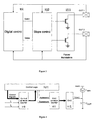
- a simplified driving circuit 100 for implementing this method is shown in figure 3 .
- a digital control unit 101 is connected both to coil driving outputs OUT1 and OUT2 and two a slope control unit 102.
- the slope control unit 102 is connected to driving transistors 103 for each output OUT1, OUT2. In this manner the slope control 102 can control driving transistors 103 in such a manner as to vary the slope of the driving waveform.
- a control up down counter 110 is provided. This counter is operable to receive timing signals f 1 , f 2 , enabling counter 110 to generate count signals at rate f 1 or f 2 as desired.
- the signals f 1 , f 2 may be generated by any suitable means including an oscillator (not shown).
- the control counter 110 is operable to output count signals to the control unit 101 and is operable to switch the rate of these count signals in response to control unit 101.
- the control unit receives count signals from counter 110 at rate f 1 .
- the control unit receives count signals from counter 110 at rate f 2 .
- the control unit increments a second counter 111 up or down by a single unit (more rapid updating can reduce the stability of the system) depending on the status of the count of first counter 110.
- the output of the second counter 111 is connected to a digital to analogue converter 112.
- the digital to analogue converter 112 In response to the level of the second counter 111 input at the end of the decrementing phase, the digital to analogue converter 112 generates a current signal I DAC .
- the second counter 111 is updated and a consequent change in I DAC is observed.
- I MIN shown in figure 3 is a constant DC current. I MIN is provided to ensure there will be a slope even when the DAC 112 output is 0.
- I DAC may be proportional to the external Vdd in order to respond quickly in changes of the supply voltage. As the system is a feedback loop, it requires some time to settle or "lock" to the correct value of the slope. Having a I DAC , proportional to Vdd allows the slope will settle to its final value very fast when the supply voltage is changed, assuming of course that the loop had already locked to a desired slope duration before the supply changes.
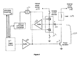
- FIG. 5 illustrates driving circuitry for a BLDC motor incorporating soft switching according to the present invention.
- power transistor 103 is controlled by digital control unit 101.
- the power transistor 103 is operable to control the application of a primary driving power source 108 (typically a voltage source) to a load 109.
- a primary driving power source 108 typically a voltage source
- the power transistor 103 is operated by the control unit 101 to vary the power applied by power source 108 in accordance with the desired driving waveform. This results in the desired driving waveform being applied to the coil, which is represented by load 109.
- the power source 108 may be an external current source.
- the negative feedback loop 120 is connected around the power transistor 103.
- the loop 120 comprises a buffer 122 and an integrating capacitor 121.
- a pair of variable current sources 123 are connected between the buffer 122 and the capacitor 121.
- the current sources 123 are powered by a second power source 107, which may be an internal power source.
- the current from the current sources 123 is integrated by capacitor 121.
- Buffer 122 is also operable to decouple the capacitor 121 from the control unit 101.
- a second buffer 106 is provided to act as a weak driver to pull the gate of the power transistor 103 either to ground or to Vdd at the end of a transition.
- the driving circuitry enables both soft switching and active slope control as described in the present invention to be implemented.
- slope control unit 102 is also provided.
- this is represented by the up down counter 111 and digital to analogue converter 112. These components are operable in the manner described in relation to figure 4 .
- the output current I DAC is used to control variable current sources 123 and thus control the slope duration in addition to softening waveform switching.
- the digital to analogue converter 112 it may be possible for the digital to analogue converter 112 to act directly as a variable current source.
Landscapes
- Engineering & Computer Science (AREA)
- Power Engineering (AREA)
- Control Of Motors That Do Not Use Commutators (AREA)
- Control Of Stepping Motors (AREA)
Abstract
Description
- The present invention relates to a method of controlling the operation of a brushless DC (BLDC) electric motor and to a motor operable in accordance therewith.
- BLDC motors are used in a wide variety of applications including as cooling fans. In operation, the coils in a BLDC motor are driven by a current flowing in one direction or the reverse direction, the direction of the current being controlled in response to signals from a sensor detecting the rotational position of the BLDC motor rotor. Typically the position sensor is a Hall effect device.
- Unfortunately, over part of their speed range, BLDC motors are prone to generate significant audible noise generated in the armature of the motor by the switching off of the stator coils.
- This noise can be reduced by 'smooth' or 'soft' switching between coils and by controlling the ramp up/down slopes of the trapezoidal driving waveforms for the coils. Soft switching may be achieved by connecting capacitors in parallel with the outputs of the drive circuitry or by designing the drive circuitry to drive with a defined trapezoidal waveform. The provision of a capacitor in parallel with the output reduces the efficiency of the motor.
- As the absolute magnitude of the waveforms is defined by the supply voltage slope control is achieved by varying the slope duration. Excessive slope duration can reduce the efficiency of the overall system by reducing the effective drive current whilst minimal slope duration can increase audible vibration in the coils and other mechanical parts. Typically, the optimum slope duration for minimising audible noise in the range of interest varies with rotation rate. In one solution, a fixed slope duration is adopted, the selected duration being optimised for an desired rotational rate. In another solution, the waveform generated by the Hall effect device is amplified and clipped to produce an approximately trapezoidal waveform. Such an arrangement can be used to produce a variation in the slope of the drive. At slow rotation rates, this can reduce the efficiency of the system since the waveform rises unnecessarily slowly. Another drawback is that this solution requires a linear amplification chain from the magnetic sensor to the output drivers (including both of them) which is hard to achieve especially for the output drivers. Moreover it is inapplicable in a two-coil, open drain output driver.
- It is therefore an object of the present invention to provide a method of controlling a brushless DC motor that at least partially overcomes or alleviates the above problems.
- According to a first aspect of the present invention there is provided a method of controlling the slope duration of a driving waveform for a brushless DC motor, the method comprising: detecting the start of the up slope of a new driven period of a driving waveform and activating an up-down counter in to count in a first direction at a first frequency in response thereto; detecting the start of the down slope of said driven period of said driving waveform and activating the up-down counter to count in a reverse direction at a second frequency in response thereto; detecting the end of the down slope of said driven period of said driving waveform and stopping the up-down counter in response thereto; determining the value of the counter when stopped; and thereby determining whether the slope duration should be increased or decreased.
- Using the above method it is possible, by appropriate selection of the first and second frequencies, to determine at any particular time whether the down slope duration is greater or lesser than a desired proportion of the driven period duration. Accordingly, the slope duration can then be increased or decreased as required.
- Preferably, the ratio of the second frequency to the first frequency is substantially equal to the desired ratio of the driven period to slope duration. The ratio may be preset. In alternative embodiments, the ratio may be controllably varied.
- In a typical motor, the optimum slope duration in the audible noise range of operation may be around 10% of the phase duration. In such circumstances the second frequency of the counter is preferably ten times the first frequency of the counter.
- The waveforms may be generated under the direction of a digital control unit. The up-down counter may be provided within the digital control unit. The up-down counter may be reset for each successive driven period.
- The value of the count when stopped may be used to increment or decrement a slope duration control block as required. The slope duration control block may be provided within the digital control unit. The slope duration may be varied, if required, by the slope duration control block by a single preset increment or decrement for each driven period. This helps to maintain stable operation.
- The driving waveform may be a trapezoidal or substantially trapezoidal waveform. The driving waveform may be a truncated sinusoid.
- According to a second aspect of the present invention there is provided a BLDC motor operable in accordance with the method of the first aspect of the present invention.
- The motor of the second aspect of the present invention may incorporate any or all features of the first aspect of the invention as desired or as appropriate. This thus provides a BLDC motor operable to variably control of the slope duration of the driving waveform with respect to motor speed.
- The BLDC motor may be a single phase BLDC motor. In alternative embodiments, the BLDC motor may have multiple (i.e. two or more) phases. The BLDC motor may incorporate a digital motor control unit. If required or desired, one or more other units may additionally be incorporated in order to implement the method of the first aspect of the present invention.
- The slope duration may be measured and controlled by one or more up-down counters. In one embodiments, there may be a first control counter and a second output counter. The first counter is operable to receive timing signals from one or more oscillators. The timing signals allow the first counter to count at the desired frequency. The second counter may be operable to increment or decrement in response to the output of the first counter and/or the motor control unit. In a preferred embodiment, the second counter may be operable to increment or decrement only once per driving period, in response to the motor control unit. This increment or decrement may be by one unit per driving period. This helps to maintain stability. The second counter may be connected to a digital to analogue converter. The digital to analogue converter may be operable to convert the output of the second counter to a control signal. The control signal may be connected to means for controlling the slope duration.
- The digital to analogue converter may be an expanding digital to analogue converter. This enables accuracy to be maintained over a wide range of different integrating currents (corresponding to different slope durations). This also improves the minimum response time between different slope durations.
- According to a third aspect of the present invention there is provided a BLDC motor comprising: a primary driving power source; a power transistor operable to control the operation of the primary driving power source; a motor control unit operable to control the operation of the driving transistor; a negative feedback loop provided around said power transistor, the negative feedback loop also incorporating an integrating capacitor wherein the integrating capacitor is operable to integrate and input from a secondary power source.
- The presence of the integrating capacitor in the negative feedback loop allows the smooth switching of the driving waveform, with a defined slope duration and is controllable independent of load variation. Additionally, it has less detrimental effect on efficiency than the prior art design having a capacitor in parallel with the power source.
- The BLDC motor may be a single phase BLDC motor. In alternative embodiments, the BLDC motor may have multiple (i.e. two or more) phases. The motor control unit may be a digital motor control unit.
- The secondary power source may connect to the integrating capacitor via one or more current sources. The current sources may be variable current sources. The output of the current sources may be controllably varied in response to signals from a connected unit. The connected unit may be the motor control unit or may be a distinct unit under the control of the motor control unit.
- The negative feedback loop may also comprise a voltage buffer. The voltage buffer is preferably a buffering amplifier. This decouples the motor control unit from the integrating capacitor. A second buffer or gate driver may be provided between the motor control unit and the negative feedback loop. This may have limited driving capacity and may act as a weak driver to pull the gate of the power transistor either to ground or to Vdd at the end of a transition.
- The primary and secondary power sources may be internal power sources or may be implemented by connections to external power sources.
- In other embodiments, the BLDC motor of the third aspect of the present invention may be operable in accordance with the method of the first aspect of the present invention. This would provide a motor implementing both slope control and soft switching. In such an embodiment, the motor of the third aspect of the present invention may incorporate any or all features of the method of the first aspect of the present invention or of the motor of the second aspect of the present invention as desired or as appropriate.
- In order that the present invention is more clearly understood, one embodiment is described further below, by way of example only, and with reference to the accompanying drawings, in which:
- Figure 1
- is a schematic diagram illustrating the optimum slope duration with respect to motor speed
- Figure 2a
- is a schematic illustration of a trapezoidal driving waveform for one phase of a two phase BLDC motor;
- Figure 2b
- is a schematic illustration of the clock counts in operation according to the method of the present invention for controlling the slope duration of the trapezoidal driving waveform;
- Figure 2c
- is a schematic illustration of the counter output corresponding to the clock counts of
figure 2b ; - Figure 3
- is a simplified schematic block diagram of a driving circuit for a BLDC motor incorporating a slope control according to the present invention;
- Figure 4
- is a schematic block diagram illustrating how slope control according to the present invention may be implemented;
- Figure 5
- is a schematic block diagram of a driving circuit for a BLDC motor incorporating soft switching according to the present invention; and
- Figure 6
- is a schematic block diagram of a driving circuit for a BLDC motor incorporating both slope control and soft switching according to the present invention.
- BLDC motors driven by square waveforms commonly generate significant audible noise over part of their operating speed range. In order to limit this noise, it is necessary to use trapezoidal waveforms and to control the duration of the ramp up/down slopes of the driving waveform. Turning now to
figure 1 , an illustration of the variation of the optimum slope duration with respect to motor speed is shown. In the figure MS1 and MS2, represent the lower and upper motor speeds wherein control of the slope duration is required. At speeds above MS2 the slope duration can remain fixed at SDmin without adverse effect on audible noise. Similarly at speeds below MS1, the slope duration can remain fixed at SDmax without adverse effect on audible noise. In between MS1 and MS2, the optimum slope duration is substantially inversely proportional to motor speed. More conveniently, the optimum slope duration is expressed as a proportion of the duration of the driven portion of the waveform and might typically be of the order of 10%. - The present invention provides a control method by means of which the slope duration can be varied as required with respect to motor speed. The method is illustrated in
figure 2 . - Turning first to
figure 2a , a trapezoidal driving waveform for one phase of a 2 phase BLDC motor is shown. For one half of the motor rotation period T, the phase is driven by the trapezoidal waveform and for the other half period, the coil remains undriven. Accordingly, if the optimum slope duration is around 10% of the duration of the driven portion, then it is of the order of T/20. - Turning now to
figure 2b , the relative duration of the slope to the duration of the driven period is measured by use of an up-down counter. The up-down counter is operable to increment at a first frequency f1 and to decrement at a second frequency f2. Incrementing operation is initiated at the start of the driven period of the waveform and stopped at the start of the down slope of the waveform(or, if desired at the start of the up slope of another (the other for a two coil system) output's driving waveform). Decrementing operation is initiated at the start of the down slope of the waveform and stopped at the end of the down slope (also the end of the driven period of the waveform). In a multi-coil system, the reverse counting may alternatively be stopped at the intercept point of the two output waveforms. - The ratio of frequencies f1:f2 is used to measure the relative duration of the slope to the driven period and is selected to mirror the desired ratio of slope duration:driven period duration. If the ratio of frequencies f1:f2 is equal to the ratio slope duration:driven period duration then the counter should register zero when stopped. If however the counter output is less than zero, it indicates that the slope duration is greater than the desired duration. Conversely, if the counter output is greater than zero, it indicates that the slope duration is less than the desired duration. This situation is illustrated in
figure 2c wherein the counter value is plotted. As can be seen, the counter is stopped before it has counted back down to zero and thus the slope duration is less than the desired duration and should be increased. - As the value of the remaining count indicates not only whether the slope duration is too long or too short, but also by how much. As such, the output of the counter can be used to increment/decrement the control register of the waveform generator for the motor to vary the slope duration as required.
- A simplified driving circuit 100 for implementing this method is shown in
figure 3 . In the circuit 100, adigital control unit 101 is connected both to coil driving outputs OUT1 and OUT2 and two aslope control unit 102. Theslope control unit 102 is connected to drivingtransistors 103 for each output OUT1, OUT2. In this manner theslope control 102 can control drivingtransistors 103 in such a manner as to vary the slope of the driving waveform. - Turning now to
figure 4 , an illustration of the components ofdigital control 101 operable to generate a control signal forslope control 102 is shown. A control up downcounter 110 is provided. This counter is operable to receive timing signals f1, f2, enabling counter 110 to generate count signals at rate f1 or f2 as desired. The signals f1, f2 may be generated by any suitable means including an oscillator (not shown). - The
control counter 110 is operable to output count signals to thecontrol unit 101 and is operable to switch the rate of these count signals in response to controlunit 101. During incrementing operation, the control unit receives count signals fromcounter 110 at rate f1. During decrementing operation, the control unit receives count signals fromcounter 110 at rate f2. At the end of the driving period, the control unit increments a second counter 111 up or down by a single unit (more rapid updating can reduce the stability of the system) depending on the status of the count offirst counter 110. - The output of the second counter 111 is connected to a digital to
analogue converter 112. In response to the level of the second counter 111 input at the end of the decrementing phase, the digital toanalogue converter 112 generates a current signal IDAC. At the end of a driving period, the second counter 111 is updated and a consequent change in IDAC is observed. The DAC current IDAC is integrated over an integrating capacitor to produce a linear slope dUc(t)=(1/C)*int(IDAC(t)*dt). Accordingly, the current IDAC is thus used to control the slope duration of the driving waveform. IMIN shown infigure 3 is a constant DC current. IMIN is provided to ensure there will be a slope even when theDAC 112 output is 0. - Typically, IDAC may be proportional to the external Vdd in order to respond quickly in changes of the supply voltage. As the system is a feedback loop, it requires some time to settle or "lock" to the correct value of the slope. Having a IDAC, proportional to Vdd allows the slope will settle to its final value very fast when the supply voltage is changed, assuming of course that the loop had already locked to a desired slope duration before the supply changes.
-
Figure 5 illustrates driving circuitry for a BLDC motor incorporating soft switching according to the present invention. In the example shownpower transistor 103 is controlled bydigital control unit 101. Thepower transistor 103 is operable to control the application of a primary driving power source 108 (typically a voltage source) to aload 109. In practice, this means thepower transistor 103 is operated by thecontrol unit 101 to vary the power applied by power source 108 in accordance with the desired driving waveform. This results in the desired driving waveform being applied to the coil, which is represented byload 109. The power source 108 may be an external current source. - The
negative feedback loop 120 is connected around thepower transistor 103. Theloop 120 comprises abuffer 122 and an integratingcapacitor 121. A pair of variablecurrent sources 123 are connected between thebuffer 122 and thecapacitor 121. Thecurrent sources 123 are powered by asecond power source 107, which may be an internal power source. The current from thecurrent sources 123 is integrated bycapacitor 121. As a result, this moderates rapid switches of thepower transistor 103 leading to smooth or soft switching of the driving waveform, reducing noise.Buffer 122 is also operable to decouple thecapacitor 121 from thecontrol unit 101. Asecond buffer 106 is provided to act as a weak driver to pull the gate of thepower transistor 103 either to ground or to Vdd at the end of a transition. - In
figure 6 , a further embodiment is shown. In this case, the driving circuitry enables both soft switching and active slope control as described in the present invention to be implemented. This varies from the embodiment offigure 5 in thatslope control unit 102 is also provided. In the example offigure 6 this is represented by the up down counter 111 and digital toanalogue converter 112. These components are operable in the manner described in relation tofigure 4 . In the present example however, the output current IDAC is used to control variablecurrent sources 123 and thus control the slope duration in addition to softening waveform switching. In alternative embodiments, it may be possible for the digital toanalogue converter 112 to act directly as a variable current source. - It is of course to be understood that the present invention is not to be restricted to the details of the above embodiment which is described by way of example only.
Claims (18)
- A method of controlling the slope duration of a driving waveform for a brushless DC motor, the method comprising: detecting the start of the up slope of a new driven period of a driving waveform and activating an up-down counter in to count in a first direction at a first frequency in response thereto; detecting the start of the down slope of said driven period of said driving waveform and activating the up-down counter to count in a reverse direction at a second frequency in response thereto; detecting the end of the down slope of said driven period of said driving waveform and stopping the up-down counter in response thereto; determining the value of the counter when stopped; and thereby determining whether the slope duration should be increased or decreased.
- A method as claimed in claim 1 wherein the ratio of the second frequency to the first frequency is substantially equal to the desired ratio of the driven period to slope duration.
- A method as claimed in claim 1 or claim 2 wherein the waveforms are generated under the direction of a digital control unit and the up-down counter is provided within the digital control unit.
- A method as claimed in any preceding claim wherein the up-down counter is reset for each successive driven period.
- A method as claimed in any preceding claim wherein the value of the count when stopped is used to increment or decrement a slope duration control block as required.
- A method as claimed in any preceding claim wherein the driving waveform is a substantially trapezoidal waveform or a truncated sinusoid.
- A BLDC motor comprising operable in accordance with the method of any one of claims 1 to 6.
- A BLDC motor as claimed in claim 7 wherein the BLDC motor is a single phase BLDC motor or a multiple phase BLDC motor and in either case incorporating a digital motor control unit.
- A BLDC motor as claimed in claim 7 or claim 8 wherein there is a first control counter and a second output counter, the first counter operable to receive timing signals from one or more oscillators and the second counter operable to increment or decrement in response to the output of the first counter and/or the motor control unit.
- A BLDC motor as claimed in claim 9 wherein the second counter is operable to increment or decrement only once per driving period and the increment or decrement is by one unit per driving period.
- A BLDC motor as claimed in claim 9 or claim 10 wherein the second counter is connected to a digital to analogue converter operable to convert the output o:'the second counter to a control signal, the control signal being connected to means for controlling the slope duration.
- A BLDC motor comprising: a primary driving power source; a power transistor operable to control the operation of the primary driving power source; a motor control unit operable to control the operation of the driving transistor; a negative feedback loop provided around said power transistor, the negative feedback loop also incorporating an integrating capacitor wherein the integrating capacitor is operable to integrate and input from a secondary power so urce.
- A BLDC motor as claimed in claim 12 wherein the BLDC motor is a single phase BLDC motor or a multiple phase BLDC motor and in either case incorporates a digital motor control unit
- A BLDC motor as claimed in claim 12 or claim 13 wherein the secondary power source connects to the integrating capacitor via one or more variable current sources.
- A BLDC motor as claimed in any one of claims 12 to 14 wherein the output of the current sources is controllably varied in response to signals from the motor control unit or a distinct unit under the control of the motor control unit.
- A BLDC motor as claimed in any one of claims 12 to 15 wherein the negative feedback loop also comprises a voltage buffer.
- A BLDC motor as claimed in claim 15 or claim 16 wherein a second buffer or gate driver is provided, between the motor control unit and the negative feedback loop.
- A BLDC motor as claimed in any one of claims 12 to 17 wherein the motor incorporates the features of any one of claims 8 to 11 and/or is operable according to the method of claims 1 to 6.
Applications Claiming Priority (1)
| Application Number | Priority Date | Filing Date | Title |
|---|---|---|---|
| GBGB0722740.8A GB0722740D0 (en) | 2007-11-20 | 2007-11-20 | Improvements in or relating to bldc motors |
Publications (2)
| Publication Number | Publication Date |
|---|---|
| EP2063528A2 true EP2063528A2 (en) | 2009-05-27 |
| EP2063528A3 EP2063528A3 (en) | 2014-05-14 |
Family
ID=38925750
Family Applications (1)
| Application Number | Title | Priority Date | Filing Date |
|---|---|---|---|
| EP08020168.4A Withdrawn EP2063528A3 (en) | 2007-11-20 | 2008-11-19 | Improvements in or relating to BLDC motors |
Country Status (3)
| Country | Link |
|---|---|
| US (1) | US8203296B2 (en) |
| EP (1) | EP2063528A3 (en) |
| GB (1) | GB0722740D0 (en) |
Families Citing this family (5)
| Publication number | Priority date | Publication date | Assignee | Title |
|---|---|---|---|---|
| CN101257291B (en) * | 2008-03-31 | 2010-12-08 | 北大方正集团有限公司 | A trapezoidal excitation pulse generation method and device |
| GB0815672D0 (en) * | 2008-08-28 | 2008-10-08 | Melexis Nv | Improvements of accuracy of rotor position detection relating to the control of brushless dc motors |
| JP5731755B2 (en) * | 2009-06-08 | 2015-06-10 | ローム株式会社 | Motor drive circuit |
| JP2012253542A (en) * | 2011-06-02 | 2012-12-20 | Ricoh Co Ltd | Motor speed control device and image forming apparatus |
| CN105322842B (en) * | 2014-08-01 | 2019-07-12 | 昆山广兴电子有限公司 | The drive control method and driving control system of motor |
Family Cites Families (22)
| Publication number | Priority date | Publication date | Assignee | Title |
|---|---|---|---|---|
| US4746844A (en) * | 1985-07-16 | 1988-05-24 | Maghemite Inc. | Control and operation of brushless continuous torque toroid motor |
| US4772839A (en) * | 1987-10-27 | 1988-09-20 | General Electric Company | Rotor position estimator for switched reluctance motor |
| US4928043A (en) * | 1988-11-14 | 1990-05-22 | Synektron Corporation | Back EMF sampling circuit for phase locked loop motor control |
| US5001405A (en) * | 1989-09-27 | 1991-03-19 | Seagate Technology, Inc. | Position detection for a brushless DC motor |
| US4992710A (en) * | 1989-09-27 | 1991-02-12 | Seagate Technology, Inc. | Position detection for a brushless DC motor with sample time optimization |
| AU630820B2 (en) * | 1990-07-04 | 1992-11-05 | Matsushita Electric Industrial Co., Ltd. | Brushless dc motor |
| JP2633984B2 (en) * | 1990-10-12 | 1997-07-23 | 株式会社三協精機製作所 | Drive circuit for brushless motor |
| US5097190A (en) * | 1991-02-11 | 1992-03-17 | General Electric Company | Rotor position estimator for a switched reluctance machine |
| US5134349A (en) * | 1991-05-28 | 1992-07-28 | Kruse David L | Two-phase brushless dc motor controller |
| US5191270A (en) * | 1991-06-07 | 1993-03-02 | Sgs-Thomson Microelectronics, Inc. | Method for starting a motor |
| US5191269A (en) * | 1991-10-10 | 1993-03-02 | Sgs-Thomson Microelectronics, Inc. | Brushless direct current motor with minimized current ripple and method |
| US5525874A (en) * | 1995-01-30 | 1996-06-11 | Delco Electronics Corp. | Digital slope compensation in a current controller |
| US6107772A (en) * | 1997-09-26 | 2000-08-22 | Dana Corporation | Sensorless switched reluctance motor control |
| US6072289A (en) * | 1998-04-28 | 2000-06-06 | Texas Instruments Incorporated | System and method for controlling high side slew rate in a spindle motor driver |
| JP2000287477A (en) * | 1999-03-29 | 2000-10-13 | Mitsubishi Electric Corp | Motor drive |
| US6011368A (en) * | 1999-03-30 | 2000-01-04 | Dana Corporation | Sensorless detection of a locked rotor in a switched reluctance motor |
| ITMI20012835A1 (en) * | 2001-12-28 | 2003-06-28 | Abb Service Srl | PROCEDURE FOR DETERMINING THE ROTOR POSITION OF A SYNCHRONOUS ALTERNATING CURRENT MACHINE WITH PERMANENT MAGNETS |
| US6958877B2 (en) * | 2001-12-28 | 2005-10-25 | Matsushita Electric Industrial Co., Ltd. | Brushless motor and disk drive apparatus |
| US6828753B2 (en) * | 2002-08-26 | 2004-12-07 | International Rectifier Corporation | Input filter for A.C. motor phase current sensing |
| JP4020100B2 (en) * | 2004-06-14 | 2007-12-12 | ソニー株式会社 | Disk drive device and motor driver circuit |
| ITTO20040399A1 (en) * | 2004-06-16 | 2004-09-16 | Univ Catania | CONTROL SYSTEM AND METHOD FOR ELECTRIC DRIVES WITH AC MOTORS. |
| US8030867B1 (en) * | 2006-07-29 | 2011-10-04 | Ixys Ch Gmbh | Sample and hold time stamp for sensing zero crossing of back electromotive force in 3-phase brushless DC motors |
-
2007
- 2007-11-20 GB GBGB0722740.8A patent/GB0722740D0/en not_active Ceased
-
2008
- 2008-11-19 EP EP08020168.4A patent/EP2063528A3/en not_active Withdrawn
- 2008-11-20 US US12/275,066 patent/US8203296B2/en not_active Expired - Fee Related
Also Published As
| Publication number | Publication date |
|---|---|
| EP2063528A3 (en) | 2014-05-14 |
| US8203296B2 (en) | 2012-06-19 |
| GB0722740D0 (en) | 2008-01-02 |
| US20090134824A1 (en) | 2009-05-28 |
Similar Documents
| Publication | Publication Date | Title |
|---|---|---|
| US7443119B2 (en) | Circuit and method for controlling the rotating speed of a BLDC motor | |
| US6879120B2 (en) | Speed control circuit of brushless DC fan motor | |
| NL1023532C2 (en) | Speed control for a brushless DC motor. | |
| US6703803B2 (en) | Fan motor driving circuit | |
| EP3059852B1 (en) | A single phase motor drive circuit and a method of driving a single phase motor | |
| KR101717066B1 (en) | Method for starting a brushless sensorless dc motor | |
| JP2563523B2 (en) | Drive device for brushless motor | |
| US7834565B2 (en) | Method of controlling a brushless DC motor | |
| US20100026219A1 (en) | Motor drive circuit with short startup time | |
| US8203296B2 (en) | BLDC motors | |
| US20080272720A1 (en) | Accurate motor speed control | |
| US20070013339A1 (en) | Motor control method and device thereof | |
| JPH0683584B2 (en) | Synchronous motor controller | |
| TWI399030B (en) | Motor controlling apparatus | |
| JP3565165B2 (en) | Brushless motor for vibration | |
| US7141945B2 (en) | Method and apparatus for controlling motor drive | |
| JP3459808B2 (en) | Motor driving circuit and driving method thereof | |
| JP2010283908A (en) | Drive circuit of brushless motor, drive method, and motor unit and electronic equipment using the same | |
| CN109578310B (en) | Fan rotating speed control circuit | |
| CN102291063A (en) | Driving system for fan and method of driving fan | |
| JP2010104113A (en) | Motor control circuit, motor device equipped therewith, and motor control method | |
| KR900007584B1 (en) | Brushless Motor Drive and Control System | |
| JP2010104115A (en) | Motor control circuit, motor device equipped therewith, and motor control method | |
| JPH07327395A (en) | Method for driving dc brushless motor | |
| Hirave et al. | Speed Control of BLDC Motor Using DSPIC30F4011 Processor |
Legal Events
| Date | Code | Title | Description |
|---|---|---|---|
| PUAI | Public reference made under article 153(3) epc to a published international application that has entered the european phase |
Free format text: ORIGINAL CODE: 0009012 |
|
| AK | Designated contracting states |
Kind code of ref document: A2 Designated state(s): AT BE BG CH CY CZ DE DK EE ES FI FR GB GR HR HU IE IS IT LI LT LU LV MC MT NL NO PL PT RO SE SI SK TR |
|
| AX | Request for extension of the european patent |
Extension state: AL BA MK RS |
|
| RAP1 | Party data changed (applicant data changed or rights of an application transferred) |
Owner name: MELEXIS TECHNOLOGIES NV |
|
| RIC1 | Information provided on ipc code assigned before grant |
Ipc: H02P 6/10 20060101ALI20140127BHEP Ipc: H02P 6/22 20060101ALI20140127BHEP Ipc: H02P 25/02 20060101AFI20140127BHEP |
|
| PUAL | Search report despatched |
Free format text: ORIGINAL CODE: 0009013 |
|
| AK | Designated contracting states |
Kind code of ref document: A3 Designated state(s): AT BE BG CH CY CZ DE DK EE ES FI FR GB GR HR HU IE IS IT LI LT LU LV MC MT NL NO PL PT RO SE SI SK TR |
|
| AX | Request for extension of the european patent |
Extension state: AL BA MK RS |
|
| RIC1 | Information provided on ipc code assigned before grant |
Ipc: H02P 25/02 20060101AFI20140404BHEP Ipc: H02P 6/10 20060101ALI20140404BHEP Ipc: H02P 6/22 20060101ALI20140404BHEP |
|
| AKY | No designation fees paid | ||
| AXX | Extension fees paid |
Extension state: MK Extension state: AL Extension state: BA Extension state: RS |
|
| REG | Reference to a national code |
Ref country code: DE Ref legal event code: R108 |
|
| REG | Reference to a national code |
Ref country code: DE Ref legal event code: R108 Effective date: 20150121 |
|
| STAA | Information on the status of an ep patent application or granted ep patent |
Free format text: STATUS: THE APPLICATION IS DEEMED TO BE WITHDRAWN |
|
| 18D | Application deemed to be withdrawn |
Effective date: 20141115 |