EP2063437A1 - Coaxial Cable - Google Patents
Coaxial Cable Download PDFInfo
- Publication number
- EP2063437A1 EP2063437A1 EP07291406A EP07291406A EP2063437A1 EP 2063437 A1 EP2063437 A1 EP 2063437A1 EP 07291406 A EP07291406 A EP 07291406A EP 07291406 A EP07291406 A EP 07291406A EP 2063437 A1 EP2063437 A1 EP 2063437A1
- Authority
- EP
- European Patent Office
- Prior art keywords
- conductor
- perfluoralkoxy
- foamed
- coaxial cable
- cable according
- Prior art date
- Legal status (The legal status is an assumption and is not a legal conclusion. Google has not performed a legal analysis and makes no representation as to the accuracy of the status listed.)
- Withdrawn
Links
- 239000004020 conductor Substances 0.000 claims abstract description 87
- RYGMFSIKBFXOCR-UHFFFAOYSA-N Copper Chemical compound [Cu] RYGMFSIKBFXOCR-UHFFFAOYSA-N 0.000 claims description 13
- 239000010949 copper Substances 0.000 claims description 13
- 229910052802 copper Inorganic materials 0.000 claims description 13
- 239000007787 solid Substances 0.000 claims description 13
- ATJFFYVFTNAWJD-UHFFFAOYSA-N Tin Chemical compound [Sn] ATJFFYVFTNAWJD-UHFFFAOYSA-N 0.000 claims description 8
- 239000007789 gas Substances 0.000 claims description 8
- 239000004812 Fluorinated ethylene propylene Substances 0.000 claims description 7
- 229920009441 perflouroethylene propylene Polymers 0.000 claims description 7
- IJGRMHOSHXDMSA-UHFFFAOYSA-N Atomic nitrogen Chemical compound N#N IJGRMHOSHXDMSA-UHFFFAOYSA-N 0.000 claims description 6
- 239000011248 coating agent Substances 0.000 claims description 6
- 238000000576 coating method Methods 0.000 claims description 6
- 238000004519 manufacturing process Methods 0.000 claims description 6
- 238000000034 method Methods 0.000 claims description 6
- 238000005187 foaming Methods 0.000 claims description 5
- BQCADISMDOOEFD-UHFFFAOYSA-N Silver Chemical compound [Ag] BQCADISMDOOEFD-UHFFFAOYSA-N 0.000 claims description 4
- 239000004411 aluminium Substances 0.000 claims description 4
- 229910052782 aluminium Inorganic materials 0.000 claims description 4
- XAGFODPZIPBFFR-UHFFFAOYSA-N aluminium Chemical compound [Al] XAGFODPZIPBFFR-UHFFFAOYSA-N 0.000 claims description 4
- 229910052751 metal Inorganic materials 0.000 claims description 4
- 239000002184 metal Substances 0.000 claims description 4
- 239000004332 silver Substances 0.000 claims description 4
- 229910052709 silver Inorganic materials 0.000 claims description 4
- 238000009826 distribution Methods 0.000 claims description 3
- HQQADJVZYDDRJT-UHFFFAOYSA-N ethene;prop-1-ene Chemical group C=C.CC=C HQQADJVZYDDRJT-UHFFFAOYSA-N 0.000 claims description 3
- 238000002156 mixing Methods 0.000 claims description 3
- 229910052757 nitrogen Inorganic materials 0.000 claims description 3
- 238000002844 melting Methods 0.000 claims description 2
- 230000008018 melting Effects 0.000 claims description 2
- 239000003989 dielectric material Substances 0.000 description 6
- 230000005540 biological transmission Effects 0.000 description 4
- 239000000463 material Substances 0.000 description 4
- 229920001343 polytetrafluoroethylene Polymers 0.000 description 4
- 238000001125 extrusion Methods 0.000 description 2
- -1 polytetrafluorethylene Polymers 0.000 description 2
- 229910052582 BN Inorganic materials 0.000 description 1
- PZNSFCLAULLKQX-UHFFFAOYSA-N Boron nitride Chemical compound N#B PZNSFCLAULLKQX-UHFFFAOYSA-N 0.000 description 1
- 239000004698 Polyethylene Substances 0.000 description 1
- 238000005452 bending Methods 0.000 description 1
- 238000010276 construction Methods 0.000 description 1
- 238000005520 cutting process Methods 0.000 description 1
- 230000007423 decrease Effects 0.000 description 1
- 230000007774 longterm Effects 0.000 description 1
- 238000010295 mobile communication Methods 0.000 description 1
- 239000002667 nucleating agent Substances 0.000 description 1
- 229920000573 polyethylene Polymers 0.000 description 1
- 229920000642 polymer Polymers 0.000 description 1
- 230000008092 positive effect Effects 0.000 description 1
- 238000012216 screening Methods 0.000 description 1
Images
Classifications
-
- H—ELECTRICITY
- H01—ELECTRIC ELEMENTS
- H01B—CABLES; CONDUCTORS; INSULATORS; SELECTION OF MATERIALS FOR THEIR CONDUCTIVE, INSULATING OR DIELECTRIC PROPERTIES
- H01B11/00—Communication cables or conductors
- H01B11/18—Coaxial cables; Analogous cables having more than one inner conductor within a common outer conductor
- H01B11/1834—Construction of the insulation between the conductors
- H01B11/1839—Construction of the insulation between the conductors of cellular structure
-
- H—ELECTRICITY
- H01—ELECTRIC ELEMENTS
- H01B—CABLES; CONDUCTORS; INSULATORS; SELECTION OF MATERIALS FOR THEIR CONDUCTIVE, INSULATING OR DIELECTRIC PROPERTIES
- H01B13/00—Apparatus or processes specially adapted for manufacturing conductors or cables
- H01B13/016—Apparatus or processes specially adapted for manufacturing conductors or cables for manufacturing co-axial cables
Definitions
- the present invention relates to coaxial cables in particular for radio frequency (RF) transmission.
- RF radio frequency
- An RF transmission line has a considerable impact on a system's efficiency which decreases with increasing attenuation of the RF transmission lines since a part of RF energy is converted into thermal energy.
- the RF attenuation depends on dimensions of the transmission line, on conductivity of conductors and on losses of dielectric layers.
- cables with small dimensions typically 0.141 inch (3.58 mm) and 0.250 inch (6.35 mm) are used which is defined by handling requirements and the limited space in case of cabling inside of racks or base station antennas for mobile communication systems.
- Such small cables are e.g. defined by the standard MIL-C-17/129 and MIL-C-17/130.
- Known coaxial cables as e.g. described in GB 734,679 may comprise a sheath formed continuously in succeeding steps from a thin metal strip as a tube spaced from the core having corrugations traverse to the cable length.
- Other known coaxial cables may comprise a solid polytetrafluorethylene (PTFE) dielectric with tin soaked copper braid as outer conductor or with an expanded PTE (PTE: Polytetraethylene) with corrugated outer conductor.
- PTFE polytetrafluorethylene
- PTE Polytetraethylene
- coaxial cables with a diameter of 3.58 mm made of solid PTFE dielectric and tin soaked copper braid outer conductor have an attenuation of 58 dB/100 m at 2 GHz.
- coaxial cables comprising an expanded PTE and a corrugated outer conductor have an attenuation of 52.2 dB/100 m at 2 GHz.
- the invention is based on the finding that the attenuation of a coaxial cable may be reduced when coating an inner conductor of the coaxial cable with foamed perfluoralkoxy (PFA) forming a dielectric layer. Further improvements may be achieved when using an outer conductor made of solid copper instead of tin soaked copper braid.
- the outer conductor may further be helically or annularly corrugated for improving the bending properties of the cable.
- the inventive coating contributes to an attenuation reduction of 3.58mm cables by more than 10dB/100m at 2GHz when compared with the attenuation associated with solid PTFE dielectric cables having a tin soaked outer conductor and by more than 5dB/100m at 2GHz when compared with the attenuation associated with cables with the expanded PTE which corresponds to an improvement of 19% and 10%, respectively.
- a cable made with a foamed dielectric may be made with a larger inner conductor compared to a cable made with the same dielectric material that is not foamed but solid.
- a larger inner conductor contributes to an additional attenuation reduction.
- Some applications of small cables require a minimum of electrical delay time of multiple cable runs which are cut to the same geometrical length. Since commonly used manufacturing cutting processes have a limited accuracy the minimal achievable delay time difference within a number of cable runs is limited accordingly. Due to the lower permittivity of a cable with foamed dielectric, the same geometrical length offset leads therefore to a smaller delay time difference compared to a cable with solid dielectric and higher permittivity.
- the dielectric material has been chosen so as to have a high thermal stability.
- foamed PFA dielectric which has a high foaming ratio of more than 57%.
- Such a high foaming ratio may be achieved by an extrusion process for extruding the foamed PFA onto the inner conductor.
- the tin layer of cables made with tin soaked braided outer conductors cracks after a few bends of the cable. As a consequence the shielding efficiency is reduced and passive intermodulation performance is worsened.
- the outer conductor of this invention may be formed from solid copper and may be a closed corrugated shape which increases the flexibility of the cable and provides a high screening efficiency and long term good passive intermodulation performance also after multiple bends.
- the described foamed PFA dielectric is used with tin soaked braided outer conductors, it provides a lower attenuation also for such a construction.
- the inventive cable is characterized by a reduced attenuation, by an increased power rating, by high homogeneity of the electrical delay time and by a simplified handling of the cable.
- the inventive cable may be used in base station antennas in the context of a distribution network and similar applications.
- the invention relates according to an aspect to a coaxial cable comprising a first conductor, a second conductor and a foamed perfluoralkoxy disposed between the first conductor and the second conductor.
- the foamed perfluoralkoxy forms preferably a dielectric layer coating the first conductor.
- the first conductor preferably forms an inner conductor and the second conductor preferably forms an outer conductor of the coaxial cable.
- the first conductor and/or the second conductor are helically or annularly corrugated.
- the first conductor or the second conductor comprise copper or silver plated copper or aluminium or are formed by a bimetallic conductor or metal braid.
- the foamed perfluoralkoxy coates the first conductor, wherein the second conductor surrounds the foamed perfluoralkoxy.
- the foamed perfluoralkoxy may have a foaming ratio of at least 57% and/or may be extruded.
- a thin layer of solid perfluoralkoxy is applied between inner conductor and the foamed dielectric.
- an outer sheath formed from a fluorinated ethylene propylene FEP is provided to coat the second conductor.
- the first conductor may have a diameter between 0.5, 1 and 1.5 mm, preferably 1 ⁇ 0.5 mm, the second conductor having a diameter between 3.08, 3.58 and 4.08 mm, preferably 3.58 mm ⁇ 0.5 mm.
- a solid perfluoralkoxy layer is disposed between the first conductor and the foamed perfluoralkoxy.
- the invention relates according to a further aspect to the use of the inventive coaxial cable for connecting a base station to an antenna in a radio frequency band at 2GHz or within a frequency interval between 900Mhz and 3.5Ghz or to the use of the inventive coaxial cable in a distribution network of antennas in the radio frequency band at 2GHz or within the frequency interval between 900Mhz and 3.5Ghz.
- the invention relates according to a further aspect to a method for manufacturing a coaxial cable.
- the method comprises providing a first conductor, extruding foamed perfluoralkoxy onto the first conductor and arranging a second conductor around the foamed perfluoralkoxy.
- the step of extruding the foamed perfluoralkoxy comprises melting a perfluoralkoxy using a single screw or a double screw extruder, injecting gas, preferably nitrogen, into the extruder, mixing the gas and the melted perfluoralkoxy to obtain the foamed perfluoralkoxy and coating the first conductor with the foamed perfluoralkoxy.
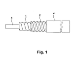
- FIG. 1 showing an embodiment of a coaxial cable.
- the coaxial cable comprises a first conductor 1 forming an inner conductor of the coaxial cable and a dielectric material surrounding or coating the first conductor 1.
- the dielectric material is foamed PFA.
- the coaxial cable further comprises a second conductor 3 forming an outer conductor of the coaxial cable and surrounding the first conductor 1 and the foamed PFA 2.
- the foamed PFA 2 is disposed as a dielectric layer between the first conductor 1 and the second conductor 3.
- the coaxial cable further comprises an outer sheath 4 surrounding the second conductor 3.
- the outer sheath 4 is preferably be made from FEP (FEP: Fluorinated Ethylene Propylene) to enable a high operating temperature.
- the foamed PFA dielectric 2 may optionally be corrugated or arranged to form closed spirals surrounding the first conductor 1.
- the second conductor 3 may comprise a helically or annularly corrugated copper, aluminium or a bimetal. Due to the helically or annularly corrugated structure, a flexibility of the coaxial cable is increased.
- the first conductor 1 is made of copper or silver plated copper and has a diameter of 1.0 ⁇ 0.5 mm.
- the dielectric PFA 2 is foamed having a foaming ratio of preferably more than 57% which can be achieved by a continuous extrusion using a gas and an appropriate nucleating agent, preferably boron nitride.
- the second conductor 3 forming the outer conductor may consist of aluminium, copper or silver plated material preferably being corrugated and having an outer diameter of 3.58 ⁇ 0.5 mm.
- the sheath material 4 is preferably solid FEP surrounding the inner structure of the coaxial cable.
- the highly conductive layer of the inner conductor is placed on the outside and the highly conductive layer of the outer conductor is placed on the inside.
- the inner conductor 3 may be drawn first.
- the foamed PFA 2 may be extruded onto the inner conductor 1.
- a single screw extruder or a double screw extruder may be used.
- a PFA material is first melted in the extruder and gas, preferably nitrogen or other gases, is injected into the melted PFA.
- the gas may preferably be mixed into the melted polymer in a mixing zone of the extruder.
- the resulting melted material may then be formed into the desired shape in a head of the extruder.
- the inner conductor 1 may be coated with the melted PFA to form the dielectric 2.
- the outer conductor 3 may be formed and the jacket 4 may be extruded.
Landscapes
- Communication Cables (AREA)
Abstract
Description
- The present invention relates to coaxial cables in particular for radio frequency (RF) transmission.
- An RF transmission line has a considerable impact on a system's efficiency which decreases with increasing attenuation of the RF transmission lines since a part of RF energy is converted into thermal energy. The RF attenuation depends on dimensions of the transmission line, on conductivity of conductors and on losses of dielectric layers.
- Commonly, cables with small dimensions of typically 0.141 inch (3.58 mm) and 0.250 inch (6.35 mm) are used which is defined by handling requirements and the limited space in case of cabling inside of racks or base station antennas for mobile communication systems. Such small cables are e.g. defined by the standard MIL-C-17/129 and MIL-C-17/130.
- Known coaxial cables as e.g. described in
GB 734,679 - It is the object of the invention to provide a coaxial cable having a reduced attenuation compared to existing solution while maintaining the standardized outer conductor diameters.
- This object is achieved by the features of the independent claims.
- The invention is based on the finding that the attenuation of a coaxial cable may be reduced when coating an inner conductor of the coaxial cable with foamed perfluoralkoxy (PFA) forming a dielectric layer. Further improvements may be achieved when using an outer conductor made of solid copper instead of tin soaked copper braid. The outer conductor may further be helically or annularly corrugated for improving the bending properties of the cable.
- The inventive coating contributes to an attenuation reduction of 3.58mm cables by more than 10dB/100m at 2GHz when compared with the attenuation associated with solid PTFE dielectric cables having a tin soaked outer conductor and by more than 5dB/100m at 2GHz when compared with the attenuation associated with cables with the expanded PTE which corresponds to an improvement of 19% and 10%, respectively.
- The invention exploits the fact that the attenuation in coaxial cables depends on the conductivity of the inner and outer conductor and on the dissipation factor of dielectric materials in the cable. When using a foamed dielectric instead of a solid the dielectric loss can be reduced significantly. Besides this the propagation velocity is increased and the permittivity is reduced when using a foamed dielectric. Since the application of said small cables requires an operating temperature of more than 200°C commonly used foamable dielectric materials like polyethylene cannot be used. Instead, this invention describes a cable made with a foamed PFA dielectric. Another positive effect of a foamed dielectric is the reduced permittivity. To accomplish the same characteristic impedance at a given outer conductor diameter a cable made with a foamed dielectric may be made with a larger inner conductor compared to a cable made with the same dielectric material that is not foamed but solid. A larger inner conductor contributes to an additional attenuation reduction. These two phenomena may collectively contribute to a reduction of attenuation of the inventive coaxial cable.
- Some applications of small cables require a minimum of electrical delay time of multiple cable runs which are cut to the same geometrical length. Since commonly used manufacturing cutting processes have a limited accuracy the minimal achievable delay time difference within a number of cable runs is limited accordingly. Due to the lower permittivity of a cable with foamed dielectric, the same geometrical length offset leads therefore to a smaller delay time difference compared to a cable with solid dielectric and higher permittivity.
- In order to fulfil high power rating requirements the dielectric material has been chosen so as to have a high thermal stability. Preferably, foamed PFA dielectric is used which has a high foaming ratio of more than 57%. Such a high foaming ratio may be achieved by an extrusion process for extruding the foamed PFA onto the inner conductor.
- The tin layer of cables made with tin soaked braided outer conductors cracks after a few bends of the cable. As a consequence the shielding efficiency is reduced and passive intermodulation performance is worsened. The outer conductor of this invention may be formed from solid copper and may be a closed corrugated shape which increases the flexibility of the cable and provides a high screening efficiency and long term good passive intermodulation performance also after multiple bends. However, if the described foamed PFA dielectric is used with tin soaked braided outer conductors, it provides a lower attenuation also for such a construction.
- Thus, the inventive cable is characterized by a reduced attenuation, by an increased power rating, by high homogeneity of the electrical delay time and by a simplified handling of the cable. Hence, the inventive cable may be used in base station antennas in the context of a distribution network and similar applications.
- The invention relates according to an aspect to a coaxial cable comprising a first conductor, a second conductor and a foamed perfluoralkoxy disposed between the first conductor and the second conductor. The foamed perfluoralkoxy forms preferably a dielectric layer coating the first conductor. The first conductor preferably forms an inner conductor and the second conductor preferably forms an outer conductor of the coaxial cable.
- According to an embodiment, the first conductor and/or the second conductor are helically or annularly corrugated.
- According to an embodiment, the first conductor or the second conductor comprise copper or silver plated copper or aluminium or are formed by a bimetallic conductor or metal braid.
- According to an embodiment, the foamed perfluoralkoxy coates the first conductor, wherein the second conductor surrounds the foamed perfluoralkoxy.
- According to an embodiment, the foamed perfluoralkoxy may have a foaming ratio of at least 57% and/or may be extruded.
- According to an embodiment, a thin layer of solid perfluoralkoxy is applied between inner conductor and the foamed dielectric.
- According to an embodiment, an outer sheath formed from a fluorinated ethylene propylene FEP is provided to coat the second conductor.
- According to an embodiment, the first conductor may have a diameter between 0.5, 1 and 1.5 mm, preferably 1 ± 0.5 mm, the second conductor having a diameter between 3.08, 3.58 and 4.08 mm, preferably 3.58 mm ± 0.5 mm.
- According to an embodiment, a solid perfluoralkoxy layer is disposed between the first conductor and the foamed perfluoralkoxy.
- The invention relates according to a further aspect to the use of the inventive coaxial cable for connecting a base station to an antenna in a radio frequency band at 2GHz or within a frequency interval between 900Mhz and 3.5Ghz or to the use of the inventive coaxial cable in a distribution network of antennas in the radio frequency band at 2GHz or within the frequency interval between 900Mhz and 3.5Ghz.
- The invention relates according to a further aspect to a method for manufacturing a coaxial cable. The method comprises providing a first conductor, extruding foamed perfluoralkoxy onto the first conductor and arranging a second conductor around the foamed perfluoralkoxy.
- Alternatively a thin layer of solid perfluoralkoxy is extruded on the inner conductor prior to the application of the foamed perfluoralkoxy.
- According to an embodiment, the step of extruding the foamed perfluoralkoxy comprises melting a perfluoralkoxy using a single screw or a double screw extruder, injecting gas, preferably nitrogen, into the extruder, mixing the gas and the melted perfluoralkoxy to obtain the foamed perfluoralkoxy and coating the first conductor with the foamed perfluoralkoxy.
- Further embodiments of the invention will be described with reference to
Fig. 1 showing an embodiment of a coaxial cable. - The coaxial cable comprises a first conductor 1 forming an inner conductor of the coaxial cable and a dielectric material surrounding or coating the first conductor 1. Preferably, the dielectric material is foamed PFA. The coaxial cable further comprises a
second conductor 3 forming an outer conductor of the coaxial cable and surrounding the first conductor 1 and thefoamed PFA 2. Thus, thefoamed PFA 2 is disposed as a dielectric layer between the first conductor 1 and thesecond conductor 3. The coaxial cable further comprises anouter sheath 4 surrounding thesecond conductor 3. Theouter sheath 4 is preferably be made from FEP (FEP: Fluorinated Ethylene Propylene) to enable a high operating temperature. The foamed PFA dielectric 2 may optionally be corrugated or arranged to form closed spirals surrounding the first conductor 1. - The
second conductor 3 may comprise a helically or annularly corrugated copper, aluminium or a bimetal. Due to the helically or annularly corrugated structure, a flexibility of the coaxial cable is increased. - Preferably, the first conductor 1 is made of copper or silver plated copper and has a diameter of 1.0 ± 0.5 mm. The
dielectric PFA 2 is foamed having a foaming ratio of preferably more than 57% which can be achieved by a continuous extrusion using a gas and an appropriate nucleating agent, preferably boron nitride. Thesecond conductor 3 forming the outer conductor may consist of aluminium, copper or silver plated material preferably being corrugated and having an outer diameter of 3.58 ± 0.5 mm. Thesheath material 4 is preferably solid FEP surrounding the inner structure of the coaxial cable. - If the inner conductor 1 and the
outer conductor 2 are bimetallic conductors then the highly conductive layer of the inner conductor is placed on the outside and the highly conductive layer of the outer conductor is placed on the inside. - In order to manufacture the coaxial cable shown in
Fig. 1 , theinner conductor 3 may be drawn first. In a further manufacturing step, the foamedPFA 2 may be extruded onto the inner conductor 1. In this step, a single screw extruder or a double screw extruder may be used. A PFA material is first melted in the extruder and gas, preferably nitrogen or other gases, is injected into the melted PFA. The gas may preferably be mixed into the melted polymer in a mixing zone of the extruder. The resulting melted material may then be formed into the desired shape in a head of the extruder. Then, the inner conductor 1 may be coated with the melted PFA to form thedielectric 2. In a next manufacturing step, theouter conductor 3 may be formed and thejacket 4 may be extruded.
Claims (10)
- A coaxial cable comprising a first conductor (1), a second conductor (3) and a foamed perfluoralkoxy (2) disposed between the first conductor (1) and the second conductor (3).
- The coaxial cable according to claim 1, the first conductor (1) or the second conductor (3) being helically or annularly corrugated.
- The coaxial cable according to claim 1 or 2, the first conductor (1) or the second conductor (3) comprising copper or silver plated copper or aluminium or being formed by a bimetallic conductor or metal braid or tin soaked metal braid.
- The coaxial cable according to anyone of the claims 1 to 4, the foamed perfluoralkoxy (2) having a foaming ratio of at least 57%.
- The coaxial cable according to anyone of the claims 1 to 5, further comprising an outer sheath (4) being formed from a fluorinated ethylene propylene.
- The coaxial cable according to anyone of the claims 1 to 6, the first conductor (1) having a diameter between 0.5, 1 and 1.5 mm, the second conductor (3) having a diameter between 3.28, 3.58 and 4.08 mm.
- The coaxial cable according to anyone of the claims 1 to 7, further comprising a solid perfluoralkoxy layer disposed between the first conductor (1) and the foamed perfluoralkoxy (2).
- The use of the coaxial cable according to anyone of the claims 1 to 8 for connecting a base station to an antenna or in a distribution network of antennas in a radio frequency band at 2GHz or within a frequency interval between 900Mhz and 3.5Ghz.
- A method for manufacturing a coaxial cable, the method comprising:- providing a first conductor (1);- extruding a foamed perfluoralkoxy (2) onto the first conductor; and- arranging a second conductor (3) around the foamed perfluoralkoxy (2).
- The method according to claim 9, the step of extruding the foamed perfluoralkoxy (2) comprising:- melting a perfluoralkoxy using a single screw or a double screw extruder;- injecting gas, preferably nitrogen, into the extruder;- mixing the gas and the melted perfluoralkoxy to obtain the foamed perfluoralkoxy; and- coating the first conductor (1) with the foamed perfluoralkoxy.
Priority Applications (1)
| Application Number | Priority Date | Filing Date | Title |
|---|---|---|---|
| EP07291406A EP2063437A1 (en) | 2007-11-26 | 2007-11-26 | Coaxial Cable |
Applications Claiming Priority (1)
| Application Number | Priority Date | Filing Date | Title |
|---|---|---|---|
| EP07291406A EP2063437A1 (en) | 2007-11-26 | 2007-11-26 | Coaxial Cable |
Publications (1)
| Publication Number | Publication Date |
|---|---|
| EP2063437A1 true EP2063437A1 (en) | 2009-05-27 |
Family
ID=39272094
Family Applications (1)
| Application Number | Title | Priority Date | Filing Date |
|---|---|---|---|
| EP07291406A Withdrawn EP2063437A1 (en) | 2007-11-26 | 2007-11-26 | Coaxial Cable |
Country Status (1)
| Country | Link |
|---|---|
| EP (1) | EP2063437A1 (en) |
Cited By (1)
| Publication number | Priority date | Publication date | Assignee | Title |
|---|---|---|---|---|
| CN104282395A (en) * | 2014-09-19 | 2015-01-14 | 中山市鸿程科研技术服务有限公司 | A kind of preparation method of coaxial cable |
Citations (7)
| Publication number | Priority date | Publication date | Assignee | Title |
|---|---|---|---|---|
| GB734679A (en) | 1951-11-14 | 1955-08-03 | Hackethal Draht & Kabelwerk Ag | Method of manufacturing electric cables with flexible metallic sheaths, particularlyof steel |
| US4368350A (en) * | 1980-02-29 | 1983-01-11 | Andrew Corporation | Corrugated coaxial cable |
| GB2143237A (en) * | 1983-07-12 | 1985-02-06 | Raychem Corp | Electrically insulating foamed polymers |
| EP0336804A2 (en) * | 1988-03-21 | 1989-10-11 | Comm/Scope Company | High frequency signal cable with improved electrical dissipation factor and method of producing same |
| US5220130A (en) * | 1991-08-06 | 1993-06-15 | Cooper Industries, Inc. | Dual insulated data cable |
| JP2006127853A (en) * | 2004-10-27 | 2006-05-18 | Fujikura Ltd | Coaxial cable and manufacturing method thereof |
| CN101051539A (en) * | 2006-04-05 | 2007-10-10 | 三菱电线工业株式会社 | Coax |
-
2007
- 2007-11-26 EP EP07291406A patent/EP2063437A1/en not_active Withdrawn
Patent Citations (7)
| Publication number | Priority date | Publication date | Assignee | Title |
|---|---|---|---|---|
| GB734679A (en) | 1951-11-14 | 1955-08-03 | Hackethal Draht & Kabelwerk Ag | Method of manufacturing electric cables with flexible metallic sheaths, particularlyof steel |
| US4368350A (en) * | 1980-02-29 | 1983-01-11 | Andrew Corporation | Corrugated coaxial cable |
| GB2143237A (en) * | 1983-07-12 | 1985-02-06 | Raychem Corp | Electrically insulating foamed polymers |
| EP0336804A2 (en) * | 1988-03-21 | 1989-10-11 | Comm/Scope Company | High frequency signal cable with improved electrical dissipation factor and method of producing same |
| US5220130A (en) * | 1991-08-06 | 1993-06-15 | Cooper Industries, Inc. | Dual insulated data cable |
| JP2006127853A (en) * | 2004-10-27 | 2006-05-18 | Fujikura Ltd | Coaxial cable and manufacturing method thereof |
| CN101051539A (en) * | 2006-04-05 | 2007-10-10 | 三菱电线工业株式会社 | Coax |
Cited By (1)
| Publication number | Priority date | Publication date | Assignee | Title |
|---|---|---|---|---|
| CN104282395A (en) * | 2014-09-19 | 2015-01-14 | 中山市鸿程科研技术服务有限公司 | A kind of preparation method of coaxial cable |
Similar Documents
| Publication | Publication Date | Title |
|---|---|---|
| JP2010080097A (en) | Coaxial cable | |
| CN201741784U (en) | Super flexible low-loss stable-phase radio-frequency cable | |
| US7795536B2 (en) | Ultra high-speed coaxial cable | |
| CA2404271A1 (en) | Mini coaxial cable for digital network | |
| WO2007077948A1 (en) | Coaxial cable | |
| CN101752639A (en) | Semi-flexible low-loss coaxial radio frequency cable for mobile base station | |
| CN102592743A (en) | Coaxial cable and manufacturing method thereof | |
| JP2008293862A (en) | Insulated wire | |
| EP2063437A1 (en) | Coaxial Cable | |
| CN104143391A (en) | High-mechanical-phase stabilization type phase-stabilizing cable and production method thereof | |
| CN204632443U (en) | a coaxial cable | |
| CN203366796U (en) | Low loss coaxial cable | |
| US9419321B2 (en) | Self-supporting stripline RF transmission cable | |
| WO2005052957A1 (en) | Coaxial cable | |
| JP2011071095A (en) | Coaxial cable and multicore coaxial cable | |
| CN209860122U (en) | High-frequency low-loss phase-stable coaxial cable | |
| WO2018201659A1 (en) | High temperature-resistant cable for mobile base station | |
| CN214848985U (en) | Phase-stabilizing radio frequency coaxial cable with ultralow temperature phase change | |
| US20130038410A1 (en) | Thermally Conductive Stripline RF Transmission Cable | |
| JP4262555B2 (en) | Thin coaxial cable and manufacturing method thereof | |
| KR20220049205A (en) | Flexible RF cable for 5G mmWave | |
| EP1103987A1 (en) | Set coil | |
| CN220208616U (en) | Light microwave stable-phase high-power coaxial radio-frequency cable | |
| KR101152391B1 (en) | Manufacturing method for micro coaxial cable having double metal shield layers | |
| CN209374094U (en) | Flat type cable |
Legal Events
| Date | Code | Title | Description |
|---|---|---|---|
| PUAI | Public reference made under article 153(3) epc to a published international application that has entered the european phase |
Free format text: ORIGINAL CODE: 0009012 |
|
| AK | Designated contracting states |
Kind code of ref document: A1 Designated state(s): AT BE BG CH CY CZ DE DK EE ES FI FR GB GR HU IE IS IT LI LT LU LV MC MT NL PL PT RO SE SI SK TR |
|
| AX | Request for extension of the european patent |
Extension state: AL BA HR MK RS |
|
| 17P | Request for examination filed |
Effective date: 20091124 |
|
| AKX | Designation fees paid |
Designated state(s): AT BE BG CH CY CZ DE DK EE ES FI FR GB GR HU IE IS IT LI LT LU LV MC MT NL PL PT RO SE SI SK TR |
|
| 17Q | First examination report despatched |
Effective date: 20100315 |
|
| RAP1 | Party data changed (applicant data changed or rights of an application transferred) |
Owner name: ALCATEL LUCENT |
|
| 111Z | Information provided on other rights and legal means of execution |
Free format text: AT BE BG CH CY CZ DE DK EE ES FI FR GB GR HU IE IS IT LI LT LU LV MC MT NL PL PT RO SE SI SK TR Effective date: 20130410 |
|
| RAP1 | Party data changed (applicant data changed or rights of an application transferred) |
Owner name: ALCATEL LUCENT |
|
| D11X | Information provided on other rights and legal means of execution (deleted) | ||
| RAP1 | Party data changed (applicant data changed or rights of an application transferred) |
Owner name: ALCATEL LUCENT |
|
| STAA | Information on the status of an ep patent application or granted ep patent |
Free format text: STATUS: THE APPLICATION IS DEEMED TO BE WITHDRAWN |
|
| 18D | Application deemed to be withdrawn |
Effective date: 20181002 |