EP2063304A2 - High power zoom lens system and image pickup apparatus - Google Patents
High power zoom lens system and image pickup apparatus Download PDFInfo
- Publication number
- EP2063304A2 EP2063304A2 EP08020253A EP08020253A EP2063304A2 EP 2063304 A2 EP2063304 A2 EP 2063304A2 EP 08020253 A EP08020253 A EP 08020253A EP 08020253 A EP08020253 A EP 08020253A EP 2063304 A2 EP2063304 A2 EP 2063304A2
- Authority
- EP
- European Patent Office
- Prior art keywords
- lens group
- lens
- high power
- power zoom
- zoom lens
- Prior art date
- Legal status (The legal status is an assumption and is not a legal conclusion. Google has not performed a legal analysis and makes no representation as to the accuracy of the status listed.)
- Withdrawn
Links
Images



















Classifications
-
- G—PHYSICS
- G02—OPTICS
- G02B—OPTICAL ELEMENTS, SYSTEMS OR APPARATUS
- G02B15/00—Optical objectives with means for varying the magnification
- G02B15/14—Optical objectives with means for varying the magnification by axial movement of one or more lenses or groups of lenses relative to the image plane for continuously varying the equivalent focal length of the objective
- G02B15/16—Optical objectives with means for varying the magnification by axial movement of one or more lenses or groups of lenses relative to the image plane for continuously varying the equivalent focal length of the objective with interdependent non-linearly related movements between one lens or lens group, and another lens or lens group
- G02B15/163—Optical objectives with means for varying the magnification by axial movement of one or more lenses or groups of lenses relative to the image plane for continuously varying the equivalent focal length of the objective with interdependent non-linearly related movements between one lens or lens group, and another lens or lens group having a first movable lens or lens group and a second movable lens or lens group, both in front of a fixed lens or lens group
- G02B15/167—Optical objectives with means for varying the magnification by axial movement of one or more lenses or groups of lenses relative to the image plane for continuously varying the equivalent focal length of the objective with interdependent non-linearly related movements between one lens or lens group, and another lens or lens group having a first movable lens or lens group and a second movable lens or lens group, both in front of a fixed lens or lens group having an additional fixed front lens or group of lenses
- G02B15/173—Optical objectives with means for varying the magnification by axial movement of one or more lenses or groups of lenses relative to the image plane for continuously varying the equivalent focal length of the objective with interdependent non-linearly related movements between one lens or lens group, and another lens or lens group having a first movable lens or lens group and a second movable lens or lens group, both in front of a fixed lens or lens group having an additional fixed front lens or group of lenses arranged +-+
-
- G—PHYSICS
- G02—OPTICS
- G02B—OPTICAL ELEMENTS, SYSTEMS OR APPARATUS
- G02B15/00—Optical objectives with means for varying the magnification
- G02B15/14—Optical objectives with means for varying the magnification by axial movement of one or more lenses or groups of lenses relative to the image plane for continuously varying the equivalent focal length of the objective
- G02B15/145—Optical objectives with means for varying the magnification by axial movement of one or more lenses or groups of lenses relative to the image plane for continuously varying the equivalent focal length of the objective having five groups only
- G02B15/1451—Optical objectives with means for varying the magnification by axial movement of one or more lenses or groups of lenses relative to the image plane for continuously varying the equivalent focal length of the objective having five groups only the first group being positive
- G02B15/145129—Optical objectives with means for varying the magnification by axial movement of one or more lenses or groups of lenses relative to the image plane for continuously varying the equivalent focal length of the objective having five groups only the first group being positive arranged +-+++
Definitions
- the present invention relates to a high power zoom lens system and an image pickup apparatus, and more particularly to a high power zoom lens system suitable for being mounted on a television camera, a video camera, and the like and an image pickup apparatus having the high power zoom lens system.
- zoom lens systems formed of four groups have been known.
- An exemplary zoom lens system formed of four groups includes in order from an object side: a first lens group having a positive refractive power; a second lens group having a negative refractive power and serving as a zooming group movable for varying power during zooming; a third lens group having a positive or a negative refractive power and correcting image plane variation accompanied by zooming; and a fourth lens group having a positive refractive power.
- Patent Document 1 Japanese Patent No. 3031598 corresponding to U.S. patent No. 5,561,560 .
- Japanese Patent No. 3031598 corresponding to U.S. patent No. 5,561,560 describes a zoom lens system that includes in order from an object side: a first lens group having a positive refractive power and remaining stationary during zooming; a second lens group formed of three groups serving as a movable lens group for zooming; a third lens group; a fourth lens group; an aperture diaphragm; and a fifth lens group used for forming an image.
- the zoom lens system has 17x zoom ratio, and is able to change a space between the third lens group and the fourth lens group to correct variation of comatic aberration accompanied by zooming by interlocking with movement of the second lens group during zooming.
- zoom lens systems mounted on a television camera and the like have high power without change of a total length of the optical system.
- the lens systems have high power of 20x magnification.
- it is hard to achieve a high power while satisfying a constraint condition of the total length of the optical system.
- it is also hard to obtain high optical performance in the entire range of zooming by suppressing aberration variation accompanied by zooming.
- the invention has been made in consideration of the situation mentioned above, and its object is to provide a high power zoom lens system capable of achieving high power without an increase in the total length of the optical system and marinating excellent optical performance by suppressing variation of spherical aberration and comatic aberration during zooming.
- a high power zoom lens system includes, in order from an object side: a first lens group, a second lens group, a third lens group, a fourth lens group and a fifth lens group.
- the first lens group has a positive refractive power and remains stationary during zooming.
- the second lens group has a negative refractive power and moving during zooming.
- the third lens group and the fourth lens group respectively have a positive refractive power and are movable relative to each other to correct image plane variation accompanied by zooming.
- the fifth lens group has a positive refractive power and including a stop, the fifth lens group being used to form an image.
- a composite lens group is formed by combining the third lens group and the fourth lens group.
- the second lens group and the composite lens group pass simultaneously through -1 ⁇ magnification points of the respective groups during zooming from a wide-angle end to a telephoto end.
- the fourth lens group has at least one aspheric surface.
- the high power zoom lens system according to the aspect of the invention employs a so-called floating mode for relatively moving the third lens group and the fourth lens group.
- a so-called floating mode for relatively moving the third lens group and the fourth lens group.
- the fourth lens group has at least, three positive lenses and one negative lens.
- the at least one aspheric surface of the fourth lens group have a shape showing that a positive refractive power is gradually reduced from an optical axis toward a periphery of the aspheric surface.
- the at least one aspheric surface of the fourth lens group be an object side surface of a positive lens of the fourth lens group closest to an image side.
- the third lens group be formed of two or less lenses.
- the second lens group may have at least one aspheric surface.
- the at least one aspheric surface of the second lens group be a surface of a negative lens of the second lens group closest to the object side.
- an image pickup apparatus includes: the high power zoom lens system mentioned above; and an image pickup device taking an object image formed by the high power zoom lens system.
- the image pickup apparatus include a television camera, a video camera, a surveillance camera, and the like.
- e-line (wavelength of 546.07 nm) is assumed as a reference wavelength.
- the zoom lens system is configured to have at least five groups.
- the configurations of the lens groups are appropriately set.
- the third lens group and the fourth lens group are operable to be movable relative to each other during zooming, and the fourth lens group is configured to have the aspheric lens.
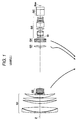
- Fig. 1 is a sectional diagram illustrating a configuration of a high power zoom lens system according to an embodiment of the invention, and corresponds to Example 1 to be described later.
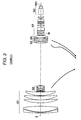
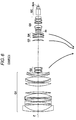
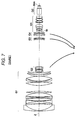
- Figs. 2 to 7 are sectional diagrams illustrating configurations of the high power zoom lens systems according to other embodiments of the invention, and correspond to high power zoom lens systems according to Examples 2 to 7.
- the left side is an object side
- the right side is an image side
- lens arrangement in a state where an object at infinity is in focus at the wide-angle end.
- moving loci of movable lens groups during zooming from the wide-angle end to the telephoto end are schematically represented by arrows under the lens arrangement.
- the zoom lens system according to each embodiment of the invention can be appropriately used by being mounted on a high-performance television camera, a high-performance video camera, and the like employing, for example, a solid-state image pickup device.
- the lens system is appropriately used in the telephoto range from the standard of 20x zoom ratio or more.
- the high power zoom lens system includes, along an optical axis Z, in order from the object side: a first lens group G1 having a positive refractive power and remaining stationary during zooming; a second lens group G2 having a negative refractive power and moving during zooming; a third lens group G3 and a fourth lens group G4 having a positive refractive power and being movable relative to each other to correct image plane variation accompanied by zooming; and a fifth lens group G5 having a positive refractive power and including an aperture diaphragm St, the fifth lens group G5 being used for forming an image.
- the aperture diaphragm St shown in each drawing does not illustrate a shape and a size thereof, but illustrates a position thereof on the optical axis Z.
- an image pickup device not shown in the drawings On an imaging plane (image pickup surface) Sim of the zoom lens system, for example, an image pickup device not shown in the drawings is disposed.
- various optical members may be disposed in accordance with a configuration of a camera equipped with the lens system.
- a color separating optical system GC including a color separating prism and the like is disposed.
- the first lens group G1 may use five-lens configuration including in order from an object side, one negative lens and four positive lenses as shown in Fig. 1 .
- the second lens group G2, the third lens group G3, and the fourth lens group G4 are movable during zooming, and have a function as zoom groups.
- the zoom lens system has a configuration of a so-called inner zoom mode of performing zooming by moving not a leading end part of the optical system but a group inside the optical system. In television cameras and video cameras, such an inner zoom mode may be preferably used since it has less change of weight balance and a total length of the optical system during zooming.
- the second lens group G2 has a function as a variator group
- the third lens group G3 and fourth lens group G4 have a function as compensator groups. More specifically, zooming is performed by moving the second lens group G2 along the optical axis, and correction of image plane variation is performed by moving the third lens group G3 and fourth lens group G4 along the optical axis.
- the zoom lens system employs a so-called floating mode in which the third lens group G3 and the fourth lens group G4 move relatively during zooming.
- the second lens group G2 and a composite lens group formed by combining the third lens group G3 and the fourth lens group G4 pass simultaneously through -1x magnification points of the groups during zooming from the wide-angle end to the telephoto end.
- the second lens group G2 may use six-lens configuration including in order from an object side: two negative lenses; a cemented lens of positive and negative lenses; and a cemented lens of positive lens and negative lenses.
- the second lens group G2 should have at least one aspheric surface. It is also preferred that a negative lens of the second lens group G2 closest to the object side should have the aspheric surface. To provide an aspheric lens to the second lens group G2 movable during zooming is advantageous in aberration correction. Furthermore, the negative lens of the zoom group located closest to the object side is formed as an aspheric lens, and thus it is possible to obtain an improved result in aberration correction.
- the third lens group G3 may be formed of one positive lens. As seen from the moving loci in Figs. 1 to 7 , during zooming from the wide-angle end to the telephoto end, the third lens group G3 does not always move in one direction from the image side to the object side, but may move in a direction opposite thereto.
- the third lens group G3 moving in such a manner has great influence on operability. Accordingly, to obtain excellent operability, it is preferred that the third lens group G3 be light in weight. Hence, it is preferred that the third lens group G3 be formed of a small number of lenses, more specifically, two or less lenses.
- the zoom lens system disclosed in Patent Document 1 allows the third lens group and fourth lens group to perform the floating mode.
- the third lens group of the zoom lens system is formed of four to five lenses. Accordingly, as compared with the zoom lens system disclosed in Patent Document 1, the zoom lens system according to the embodiment is able to obtain better operability.
- the fourth lens group may use four-lens configuration including in order from an object side: a positive lens; a cemented lens of positive and negative lenses; and a positive lens. It is preferred that the fourth lens group G4 be formed of at least, three positive lenses and one negative lens. With such a configuration, it is possible to satisfactorily correct longitudinal chromatic aberration.
- the fourth lens group G4 should have at least one aspheric surface.
- the aspheric surface be an object side surface of the positive lens of the fourth lens group G4 closest to the image side.
- an object side surface of the positive lens of the zoom group located closest to the object side is formed as an aspheric surface, and thus it is possible to obtain an improved result in aberration correction. Particularly, it is possible to satisfactorily correct spherical aberration, comatic aberration, and image field curvature.
- the at least one aspheric surface of the fourth lens group G4 should have a shape by which a positive refractive power is gradually reduced from the optical axis toward the periphery of the aspheric surface. Accordingly, the configuration is advantageous to suppress variation of various aberrations during zooming.
- the fifth lens group G5 has a function as a relay (master) group.
- the fifth lens group G5 may use eleven-lens configuration.
- the eleven-lens configuration includes in order from the object side: an aperture diaphragm St; a cemented lens of negative, positive and negative lenses; two positive lenses; a negative lens; a positive lens; a cemented lens of negative and positive lenses; and a cemented lens of negative and positive lenses.
- the zoom lens system according to the embodiment is formed of five groups as a whole, and the configuration of each lens group is appropriately set.
- the floating mode for moving relatively the third lens group G3 and the fourth lens group G4 during zooming, and the fourth lens group G4 which is the group of the zoom groups closest to the image side has a aspheric lens.
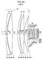
- FIG. 1 A lens sectional diagram of Example 1 is shown in Fig. 1 , and the detailed configuration is shown in Figs. 8A to 8C .
- Fig. 8A shows a detailed configuration of the first lens group G1 and the second lens group G2.
- Fig. 8B shows a detailed configuration of the third lens group G3 and the fourth lens group G4.
- Fig. 8C shows a detailed configuration from the fifth lens group G5 to the imaging plane Sim.
- the first lens group G1 has a five-lens configuration of lenses L1 to L5
- the second lens group G2 has a six-lens configuration of lenses L21 to L26
- the third lens group G3 has an one-lens configuration of a lens L31
- the fourth lens group has a four-lens configuration of lenses L41 to L44
- the fifth lens group G5 has an eleven-lens configuration of lenses L51 to L61 and an aperture diaphragm St.
- the surface data of the high power zoom lens system according to Example 1 is represented in Table 1.
- the various data thereof is represented in Table 2.
- the aspheric data thereof is represented in Table 3.
- the reference signs of Tables 1 to 3 have the same meaning the reference signs in Examples to be described later.
- Ri represents a radius of curvature of i-th surface
- Di represents an on-axis surface spacing on the optical axis Z between the i-th surface and the (i+1)th surface on the optical.
- vdj represents an Abbe number of the j-th optical element at d-line (wavelength of 587.6 nm).
- the surface numbers are also noted on the aperture diaphragm St and the color separating optical system GC.
- a direction in which the radius of curvature is convex toward the object side is defined as a positive direction
- a direction in which the radius of curvature is convex toward the image side is defined as a negative direction.
- the Ri and Di shown in Table 1 correspond to the Ri and Di in Figs. 8A to 8C .
- AP represents the aperture diaphragm
- IP represents the image plane.
- on-axis surface spacings D10, D20, D22, and D29 which are variable for zooming.
- the on-axis surface spacings correspond to a space of the first group G1 and the second group G2, a space of the second group G2 and the third group G3, and a space of the third group G3 and the fourth group G4, respectively.
- FIG. 9A shows a detailed configuration of the first lens group G1 and the second lens group G2.
- Fig. 9B shows a detailed configuration of the third lens group G3 and the fourth lens group G4.
- Fig. 9C shows a detailed configuration from the fifth lens group G5 to the imaging plane Sim.
- the first lens group G1 has a five-lens configuration of lenses L1 to L5
- the second lens group G2 has a six-lens configuration of lenses L21 to L26
- the third lens group G3 has an one-lens configuration of a lens L31
- the fourth lens group has a four-lens configuration of lenses L41 to L44
- the fifth lens group G5 has an eleven-lens configuration of lenses L51 to L61 and an aperture diaphragm St.
- the surface data of the high power zoom lens system according to Example 2 is represented in Table 4.
- the various data thereof is represented in Table 5.
- the aspheric data thereof is represented in Table 6. [Table 4] Surface data of Example 2
- FIG. 3 A lens sectional diagram of Example 3 is shown in Fig. 3 , and the detailed configuration is shown in Figs. 10A to 10C .
- Fig. 10A shows a detailed configuration of the first lens group G1 and the second lens group G2.
- Fig. 10B shows a detailed configuration of the third lens group G3 and the fourth lens group G4.
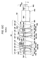
- Fig. 10C shows a detailed configuration from the fifth lens group G5 to the imaging plane Sim.
- the first lens group G1 has a five-lens configuration of lenses L1 to L5
- the second lens group G2 has a six-lens configuration of lenses L21 to L26
- the third lens group G3 has an one-lens configuration of a lens L31
- the fourth lens group has a four-lens configuration of lenses L41 to L44
- the fifth lens group G5 has an eleven-lens configuration of lenses L51 to L61 and an aperture diaphragm St.
- the surface data of the high power zoom lens system according to Example 3 is represented in Table 7.
- the various data thereof is represented in Table 8.
- the aspheric data thereof is represented in Table 9.
- Table 7 Surface data of Example 3 SNo. Ri Di Nej v dj 1 755.8203 4.400 1.83932 37.2 2 244.1862 1.800 3 242.2962 31.984 1.43496 95.1 4 -672.8827 18.620 5 271.2990 16.616 1.43496 95.1 6 1113.9934 0.120 7 217.0679 21.586 1.43496 95.1 8 1140.5834 2.502 9 187.7547 19.678 1.43985 94.9 10 573.1932 Variable *11 413.7351 3.157 1.91048 31.3 12 440.7192 3.104 13 -129.5488 1.800 2.01168 28.3 14 46.3519 7.068 15 -59.9220 1.800 1.82016 46.6 16 57.0405 5.875 1.81643 22.8 17 -346.9044 0.120
- FIG. 4 A lens sectional diagram of Example 4 is shown in Fig. 4 , and the detailed configuration is shown in Figs. 11A to 11C .
- Fig. 11A shows a detailed configuration of the first lens group G1 and the second lens group G2.
- Fig. 11B shows a detailed configuration of the third lens group G3 and the fourth lens group G4.
- Fig. 11C shows a detailed configuration from the fifth lens group G5 to the imaging plane Sim.
- the first lens group G1 has a twelve-lens configuration of lenses L1 to L12
- the second lens group G2 has a five-lens configuration of lenses L21 to L25
- the third lens group G3 has an one-lens configuration of a lens L31
- the fourth lens group has a four-lens configuration of lenses L41 to L44
- the fifth lens group G5 has an eleven-lens configuration of lenses L51 to L61 and an aperture diaphragm St.
- the surface data of the high power zoom lens system according to Example 4 is represented in Table 10.
- the various data thereof is represented in Table 11.
- the aspheric data thereof is represented in Table 12.
- [Table 10] Surface data of Example 4 SNo. Ri Di Nej v dj 1 587.7323 4.000 1.75844 52.3 2 116.6848 35.992 3 -473.2793 3.500 1.74435 52.7 4 -5216.1535 11.465 5 -226.2869 3.500 1.73233 54.7 6 697.5690 1.000 7 374.2424 14.267 1.81263 25.4 8 -583.7634 2.402 9 -999.8767 3.500 1.81763 25.4 10 625.0341 2.271 11 1259.0818 21.993 1.43496 95.1 12 -165.4801 0.120 13 625.4922 9.344 1.43496 95.1 14 -674.7695 32.709 15 216.9399 18.897 1.43496 95.1 16 -536.
- FIG. 5 A lens sectional diagram of Example 5 is shown in Fig. 5 , and the detailed configuration is shown in Figs. 12A to 12C .
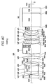
- Fig. 12A shows a detailed configuration of the first lens group G1 and the second lens group G2.
- Fig. 12B shows a detailed configuration of the third lens group G3 and the fourth lens group G4.
- Fig. 12C shows a detailed configuration from the fifth lens group G5 to the imaging plane Sim.
- the first lens group G1 has a twelve-lens configuration of lenses L1 to L12
- the second lens group G2 has a five-lens configuration of lenses L21 to L25
- the third lens group G3 has an one-lens configuration of a lens L31
- the fourth lens group has a four-lens configuration of lenses L41 to L44
- the fifth lens group G5 has an eleven-lens configuration of lenses L51 to L61 and an aperture diaphragm St.
- the surface data of the high power zoom lens system according to Example 5 is represented in Table 13.
- the various data thereof is represented in Table 14.
- the aspheric data thereof is represented in Table 15.
- [Table 13] Surface data of Example5 SNo. Ri Di Nej v dj 1 602.4249 4.000 1.75844 52.3 2 115.9533 35.906 3 -501.2490 3.500 1.74435 52.7 4 -5552.5911 11.403 5 -229.1409 3.500 1.73233 54.7 6 702.5416 1.000 7 356.4516 14.100 1.81263 25.4 8 -658.005 2.398 9 -999.9775 3.500 1.81963 25.4 10 614.8776 2.082 11 1126.0550 21.787 1.43496 95.1 12 -169.4164 0.120 13 604.5637 9.638 1.43496 95.1 14 -648.7133 32.735 15 219.7250 18.840 1.43496 95.1 16 -524.5831 0.120 17 252.2156
- FIG. 6 A lens sectional diagram of Example 6 is shown in Fig. 6 , and the detailed configuration is shown in Figs. 13A to 13C .
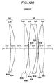
- Fig. 13A shows a detailed configuration of the first lens group G1 and the second lens group G2.
- Fig. 13B shows a detailed configuration of the third lens group G3 and the fourth lens group G4.
- Fig. 13C shows a detailed configuration from the fifth lens group G5 to the imaging plane Sim.
- the first lens group G1 has a twelve-lens configuration of lenses L1 to L12
- the second lens group G2 has a five-lens configuration of lenses L21 to L25
- the third lens group G3 has an one-lens configuration of a lens L31
- the fourth lens group has a four-lens configuration of lenses L41 to L44
- the fifth lens group G5 has an eleven-lens configuration of lenses L51 to L61 and an aperture diaphragm St.
- the surface data of the high power zoom lens system according to Example 6 is represented in Table 16.
- the various data thereof is represented in Table 17.
- the aspheric data thereof is represented in Table 18.
- [Table 16] Surface data of Example 6 SNo. Ri Di Nej v dj 1 458.8197 4.000 1.76730 50.6 2 108.6734 35.617 3 -503.0553 3.500 1.74767 52.0 4 -1979.6228 10.426 5 -235.3778 3.500 1.74893 51.4 6 620.8133 1.000 7 317.3104 14.206 1.81263 25.4 8 -856.6767 2.399 9 -991.2615 3.500 1.81263 25.4 10 675.7109 1.981 11 1287.3631 22.493 1.43496 95.1 12 -161.1693 0.120 13 985.9824 8.601 1.43496 95.1 14 -570.0800 32.574 15 199.6003 17.565 1.43496 95.1 16 -1082.3215 0.120 17 23
- FIG. 7 A lens sectional diagram of Example 7 is shown in Fig. 7 , and the detailed configuration is shown in Figs. 14A to 14C .
- Fig. 14A shows a detailed configuration of the first lens group G1 and the second lens group G2.
- Fig. 14B shows a detailed configuration of the third lens group G3 and the fourth lens group G4.
- Fig. 14C shows a detailed configuration from the fifth lens group G5 to the imaging plane Sim.
- the first lens group G1 has a twelve-lens configuration of lenses L1 to L12
- the second lens group G2 has a five-lens configuration of lenses L21 to L25
- the third lens group G3 has an two-lens configuration of lenses L31 to L32
- the fourth lens group has a three-lens configuration of lenses L41 to L43
- the fifth lens group G5 has an eleven-lens configuration of lenses L51 to L61 and an aperture diaphragm St.
- the surface data of the high power zoom lens system according to Example 7 is represented in Table 19.
- the various data thereof is represented in Table 20.
- the aspheric data thereof is represented in Table 21.
- [Table 19] Surface data of Example 7 SNo. Ri Di Nej v dj 1 471.8856 4.000 1.76670 50.8 2 107.0997 35.626 3 -548.5623 3.500 1.74696 52.1 4 -2758.8744 10.432 5 -238.3734 3.500 1.74504 52.1 6 672.3160 1.000 7 320.1460 14.215 1.81263 25.4 8 -916.9159 2.399 9 -1000.0021 3.500 1.81263 25.4 10 642.8456 1.990 11 1177.3627 22.493 1.43496 95.1 12 -162.7812 0.120 13 1111.4752 8.601 1.43496 95.1 14 -529.6422 32.584 15 207.4894 17.566 1.43496 95.1 16 -881.0461 0.120
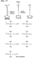
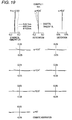
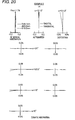
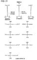
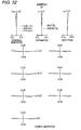
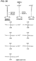
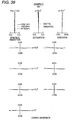
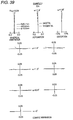
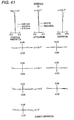
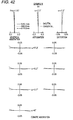
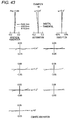
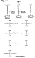
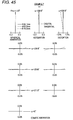
- Figs. 15 to 49 are aberration diagrams showing spherical aberration, astigmatism, distortion, and comatic aberration at magnifying powers of the high power zoom lens systems according to Examples 1 to 7.
- example numbers are represented on the top of the drawing, and jut below the numbers, magnifying powers are represented.
- aberration diagrams there are shown aberrations in which e-line (in spherical aberration diagram, a wavelength of 546.1 nm is applied) is set as a reference wavelength.
- e-line in spherical aberration diagram, a wavelength of 546.1 nm is applied
- the spherical aberration diagram there are also shown aberrations at a wavelength of 460.0 nm and a wavelength of 615.0 nm.
- the Fno is also shown.
- the ⁇ in astigmatism diagram, distortion diagram, and comatic aberration diagram represents a half angle of view. Furthermore, when a unit of surface data is mm, a unit of size of aberration in each aberration diagram is mm.
- the high power zoom lens systems according to Examples 1 to 7 is configured to be light in weight and have a high zoom ratio of 23x to 54x magnification and a F number of 1.57 to 1.76 at the wide-angle end. Furthermore, from the aberration diagrams shown in Figs. 15 to 49 , it can be observed that the high power zoom lens systems according to Examples 1 to 7 is configured to satisfactorily correct aberrations and minimize variation of aberrations including spherical aberration and comatic aberration during zooming from the wide-angle end to the telephoto end.
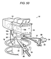
- Fig. 50 is a perspective diagram illustrating a television camera 10 which is an image pickup apparatus according to the embodiment of invention.
- the television camera 10 shown in Fig. 50 includes a lens apparatus 12 and a camera main body 14.
- the lens apparatus 12 has the high power zoom lens system 12a according to the embodiment of the invention, an image pickup device 12b for taking an object image formed by the high power zoom lens system 12a.
- the high power zoom lens system 12a is schematically illustrated.
- the television camera 10 is supported on a pan head 18 installed on the upper part of a pedestal dolly 16 to freely move in a pan direction and a tilt direction. From the pan head 18, two pan rods 22 and 23 manually operated by a camera operator extends rearward.
- a zoom demand 26 connected to the lens apparatus 12 via a cable 25 is mounted on the end of the pan rod 22.
- a focus demand 28 connected to the lens apparatus 12 via a cable 27 is mounted on the end of the pan rod 23.
- a thumb ring 30 rotatable in both directions from a reference position is disposed on the zoom demand 26.
- a zoom instruction signal based on an operation amount from the reference position that is, a rotation amount and a rotation direction is sent from the zoom demand 26 to the lens apparatus 12, and the high power zoom lens 12a of the lens apparatus 12 is zoomed toward the wide-angle side or toward the telephoto side.
- zooming is performed by a manual operation.
- focus ring (rotating member) 34 is provided to freely rotate.
- a focus instruction signal based on an operation amount, that is, a rotation amount and a rotation direction is sent from the focus demand 28 to the lens apparatus 12, the focus lens of the lens apparatus 12 is moved toward the near point or toward the infinity.
- the focusing is performed by manual operation.
- the high power zoom lens system 12a is able to achieve miniaturization with a high zoom ratio and suppress variation of spherical aberration and comatic aberration during zooming thereby having excellent optical performance.
- the television camera 10 equipped with the high power zoom lens system 12a is configured to have a small size and a function of a high zoom ratio, and is operable to form a sharp image on the image pickup surface of the image pickup device 12b.
- the invention has been hitherto described with reference to embodiments and examples, but is not limited to the embodiments and the examples, and may be modified to various forms.
- the values of the radius of curvature, the on-axis surface spacing, and the refractive index in the lens components are not limited to the values shown in the numerical examples, and may have different values.
- the television camera has been described as an example of the image pickup apparatus, but the invention is not limited to this, and may be applied to different image pickup apparatuses such as a video camera and a surveillance camera.
Landscapes
- Physics & Mathematics (AREA)
- General Physics & Mathematics (AREA)
- Optics & Photonics (AREA)
- Nonlinear Science (AREA)
- Lenses (AREA)
Abstract
Description
- The present invention relates to a high power zoom lens system and an image pickup apparatus, and more particularly to a high power zoom lens system suitable for being mounted on a television camera, a video camera, and the like and an image pickup apparatus having the high power zoom lens system.
- Generally, as zoom lens systems mounted on a television camera, a video camera, and the like, zoom lens systems formed of four groups have been known. An exemplary zoom lens system formed of four groups includes in order from an object side: a first lens group having a positive refractive power; a second lens group having a negative refractive power and serving as a zooming group movable for varying power during zooming; a third lens group having a positive or a negative refractive power and correcting image plane variation accompanied by zooming; and a fourth lens group having a positive refractive power.
- Meanwhile, zoom lens systems mounted on a television camera and the like demand good operability, a small size with high performance, and a high zoom ratio. To satisfy the demands, zoom lens systems formed of five lens groups have been proposed. For example, Patent Document 1 (Japanese Patent No.
3031598 U.S. patent No. 5,561,560 ) describes a zoom lens system that includes in order from an object side: a first lens group having a positive refractive power and remaining stationary during zooming; a second lens group formed of three groups serving as a movable lens group for zooming; a third lens group; a fourth lens group; an aperture diaphragm; and a fifth lens group used for forming an image. The zoom lens system has 17x zoom ratio, and is able to change a space between the third lens group and the fourth lens group to correct variation of comatic aberration accompanied by zooming by interlocking with movement of the second lens group during zooming. - Recently, it has been required that zoom lens systems mounted on a television camera and the like have high power without change of a total length of the optical system. Particularly, it has been further required that the lens systems have high power of 20x magnification. However, as magnifying power increases, aberration variation accompanied by zooming remarkably deteriorates. Thus, it is hard to achieve a high power while satisfying a constraint condition of the total length of the optical system. In addition, it is also hard to obtain high optical performance in the entire range of zooming by suppressing aberration variation accompanied by zooming.
- The invention has been made in consideration of the situation mentioned above, and its object is to provide a high power zoom lens system capable of achieving high power without an increase in the total length of the optical system and marinating excellent optical performance by suppressing variation of spherical aberration and comatic aberration during zooming. In addition, it is also an object of the invention to provide an image pickup apparatus having the high power zoom lens system.
- According to an aspect of the invention, a high power zoom lens system includes, in order from an object side: a first lens group, a second lens group, a third lens group, a fourth lens group and a fifth lens group. The first lens group has a positive refractive power and remains stationary during zooming. The second lens group has a negative refractive power and moving during zooming. The third lens group and the fourth lens group respectively have a positive refractive power and are movable relative to each other to correct image plane variation accompanied by zooming. The fifth lens group has a positive refractive power and including a stop, the fifth lens group being used to form an image. A composite lens group is formed by combining the third lens group and the fourth lens group. The second lens group and the composite lens group pass simultaneously through -1 × magnification points of the respective groups during zooming from a wide-angle end to a telephoto end. The fourth lens group has at least one aspheric surface.
- In the configuration having the five groups, the high power zoom lens system according to the aspect of the invention employs a so-called floating mode for relatively moving the third lens group and the fourth lens group. Thus, it is possible to satisfactorily correct image plane variation during zooming and satisfactorily suppress variation of spherical aberration and comatic aberration during zooming. In addition, by providing an aspheric lens having a high aberration correction performance to the fourth lens group used for the floating mode, it is possible to effectively suppress occurrence and variation of various aberrations. In this manner, according to the high power zoom lens system of the aspect of the invention, it is possible to embody a zoom lens system capable of achieving miniaturization with a high zoom ratio and suppressing variation of spherical aberration and comatic aberration during zooming.
- In the high power zoom lens system according to the aspect of the invention, it is preferred that the fourth lens group has at least, three positive lenses and one negative lens.
- In the high power zoom lens system according to the aspect of the invention, it is preferred that the at least one aspheric surface of the fourth lens group have a shape showing that a positive refractive power is gradually reduced from an optical axis toward a periphery of the aspheric surface.
- In the high power zoom lens system according to the aspect of the invention, it is preferred that the at least one aspheric surface of the fourth lens group be an object side surface of a positive lens of the fourth lens group closest to an image side.
- In the high power zoom lens system according to the aspect of the invention, it is preferred that the third lens group be formed of two or less lenses.
- In the high power zoom lens system according to the aspect of the invention, the second lens group may have at least one aspheric surface. In this case, It is preferred that the at least one aspheric surface of the second lens group be a surface of a negative lens of the second lens group closest to the object side.
- According to another aspect of the invention, an image pickup apparatus includes: the high power zoom lens system mentioned above; and an image pickup device taking an object image formed by the high power zoom lens system. Examples of the image pickup apparatus include a television camera, a video camera, a surveillance camera, and the like.
- Furthermore, if there is no specific description about that in the invention, e-line (wavelength of 546.07 nm) is assumed as a reference wavelength.
- According to the aspects of the invention, the zoom lens system is configured to have at least five groups. In the lens system, the configurations of the lens groups are appropriately set. In particular, the third lens group and the fourth lens group are operable to be movable relative to each other during zooming, and the fourth lens group is configured to have the aspheric lens. Thus, it is possible to provide a high power zoom lens system capable of achieving high power without increasing a total length of the optical system and maintaining excellent optical performance by suppressing variation of spherical aberration and comatic aberration during zooming. In addition, it is also possible to provide an image pickup apparatus having the high power zoom lens system.
-
-
Fig 1 is a sectional diagram illustrating a lens configuration of a high power zoom lens system according to Example 1 of the invention. -
Fig 2 is a sectional diagram illustrating a lens configuration of a high power zoom lens system according to Example 2 of the invention. -
Fig 3 is a sectional diagram illustrating a lens configuration of a high power zoom lens system according to Example 3 of the invention. -
Fig 4 is a sectional diagram illustrating a lens configuration of a high power zoom lens system according to Example 4 of the invention. -
Fig 5 is a sectional diagram illustrating a lens configuration of a high power zoom lens system according to Example 5 of the invention. -
Fig 6 is a sectional diagram illustrating a lens configuration of a high power zoom lens system according to Example 6 of the invention. -
Fig 7 is a sectional diagram illustrating a lens configuration of a high power zoom lens system according to Example 7 of the invention. -
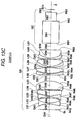
Fig. 8A is a sectional diagram illustrating a detailed configuration of a first lens group and a second lens group of the high power zoom lens system according to Example 1 of the invention. -
Fig. 8B is a sectional diagram illustrating a detailed configuration of a third lens group and a fourth lens group of the high power zoom lens system according to Example 1 of the invention. -
Fig. 8C is a sectional diagram illustrating a detailed configuration from a fifth lens group to an imaging plane of the high power zoom lens system according to Example 1 of the invention. -
Fig. 9A is a sectional diagram illustrating a detailed configuration of a first lens group and a second lens group of the high power zoom lens system according to Example 2 of the invention. -
Fig. 9B is a sectional diagram illustrating a detailed configuration of a third lens group and a fourth lens group of the high power zoom lens system according to Example 2 of the invention. -
Fig. 9C is a sectional diagram illustrating a detailed configuration from a fifth lens group to an imaging plane of the high power zoom lens system according to Example 2 of the invention. -
Fig. 10A is a sectional diagram illustrating a detailed configuration of a first lens group and a second lens group of the high power zoom lens system according to Example 3 of the invention. -
Fig. 10B is a sectional diagram illustrating a detailed configuration of a third lens group and a fourth lens group of the high power zoom lens system according to Example 3 of the invention. -
Fig. 10C is a sectional diagram illustrating a detailed configuration from a fifth lens group to an imaging plane of the high power zoom lens system according to Example 3 of the invention. -
Fig. 11A is a sectional diagram illustrating a detailed configuration of a first lens group and a second lens group of the high power zoom lens system according to Example 4 of the invention. -
Fig. 11B is a sectional diagram illustrating a detailed configuration of a third lens group and a fourth lens group of the high power zoom lens system according to Example 4 of the invention. -
Fig. 11C is a sectional diagram illustrating a detailed configuration from a fifth lens group to an imaging plane of the high power zoom lens system according to Example 4 of the invention. -
Fig. 12A is a sectional diagram illustrating a detailed configuration of a first lens group and a second lens group of the high power zoom lens system according to Example 5 of the invention. -
Fig. 12B is a sectional diagram illustrating a detailed configuration of a third lens group and a fourth lens group of the high power zoom lens system according to Example 5 of the invention. -
Fig. 12C is a sectional diagram illustrating a detailed configuration from a fifth lens group to an imaging plane of the high power zoom lens system according to Example 5 of the invention. -
Fig. 13A is a sectional diagram illustrating a detailed configuration of a first lens group and a second lens group of the high power zoom lens system according to Example 6 of the invention. -
Fig. 13B is a sectional diagram illustrating a detailed configuration of a third lens group and a fourth lens group of the high power zoom lens system according to Example 6 of the invention. -
Fig. 13C is a sectional diagram illustrating a detailed configuration from a fifth lens group to an imaging plane of the high power zoom lens system according to Example 6 of the invention. -
Fig. 14A is a sectional diagram illustrating a detailed configuration of a first lens group and a second lens group of the high power zoom lens system according to Example 7 of the invention. -
Fig. 14B is a sectional diagram illustrating a detailed configuration of a third lens group and a fourth lens group of the high power zoom lens system according to Example 7 of the invention. -
Fig. 14C is a sectional diagram illustrating a detailed configuration from a fifth lens group to an imaging plane of the high power zoom lens system according to Example 7 of the invention. -
Fig. 15 is a diagram illustrating aberrations of the high power zoom lens system according to Example 1 of the invention. -
Fig. 16 is a diagram illustrating aberrations of the high power zoom lens system according to Example 1 of the invention. -
Fig. 17 is a diagram illustrating aberrations of the high power zoom lens system according to Example 1 of the invention. -
Fig. 18 is a diagram illustrating aberrations of the high power zoom lens system according to Example 1 of the invention. -
Fig. 19 is a diagram illustrating aberrations of the high power zoom lens system according to Example 1 of the invention. -
Fig. 20 is a diagram illustrating aberrations of the high power zoom lens system according to Example 2 of the invention. -
Fig. 21 is a diagram illustrating aberrations of the high power zoom lens system according to Example 2 of the invention. -
Fig. 22 is a diagram illustrating aberrations of the high power zoom lens system according to Example 2 of the invention. -
Fig. 23 is a diagram illustrating aberrations of the high power zoom lens system according to Example 2 of the invention. -
Fig. 24 is a diagram illustrating aberrations of the high power zoom lens system according to Example 2 of the invention. -
Fig. 25 is a diagram illustrating aberrations of the high power zoom lens system according to Example 3 of the invention. -
Fig. 26 is a diagram illustrating aberrations of the high power zoom lens system according to Example 3 of the invention. -
Fig. 27 is a diagram illustrating aberrations of the high power zoom lens system according to Example 3 of the invention. -
Fig. 28 is a diagram illustrating aberrations of the high power zoom lens system according to Example 3 of the invention. -
Fig. 29 is a diagram illustrating aberrations of the high power zoom lens system according to Example 3 of the invention. -
Fig. 30 is a diagram illustrating aberrations of the high power zoom lens system according to Example 4 of the invention. -
Fig. 31 is a diagram illustrating aberrations of the high power zoom lens system according to Example 4 of the invention. -
Fig. 32 is a diagram illustrating aberrations of the high power zoom lens system according to Example 4 of the invention. -
Fig. 33 is a diagram illustrating aberrations of the high power zoom lens system according to Example 4 of the invention. -
Fig. 34 is a diagram illustrating aberrations of the high power zoom lens system according to Example 4 of the invention. -
Fig. 35 is a diagram illustrating aberrations of the high power zoom lens system according to Example 5 of the invention. -
Fig. 36 is a diagram illustrating aberrations of the high power zoom lens system according to Example 5 of the invention. -
Fig. 37 is a diagram illustrating aberrations of the high power zoom lens system according to Example 5 of the invention. -
Fig. 38 is a diagram illustrating aberrations of the high power zoom lens system according to Example 5 of the invention. -
Fig. 39 is a diagram illustrating aberrations of the high power zoom lens system according to Example 5 of the invention. -
Fig. 40 is a diagram illustrating aberrations of the high power zoom lens system according to Example 6 of the invention. -
Fig. 41 is a diagram illustrating aberrations of the high power zoom lens system according to Example 6 of the invention. -
Fig. 42 is a diagram illustrating aberrations of the high power zoom lens system according to Example 6 of the invention. -
Fig. 43 is a diagram illustrating aberrations of the high power zoom lens system according to Example 6 of the invention. -
Fig. 44 is a diagram illustrating aberrations of the high power zoom lens system according to Example 6 of the invention. -
Fig. 45 is a diagram illustrating aberrations of the high power zoom lens system according to Example 7 of the invention. -
Fig. 46 is a diagram illustrating aberrations of the high power zoom lens system according to Example 7 of the invention. -
Fig. 47 is a diagram illustrating aberrations of the high power zoom lens system according to Example 7 of the invention. -
Fig. 48 is a diagram illustrating aberrations of the high power zoom lens system according to Example 7 of the invention. -
Fig. 49 is a diagram illustrating aberrations of the high power zoom lens system according to Example 7 of the invention. -
Fig. 50 is a perspective diagram illustrating an image pickup apparatus according to an embodiment of the invention. - Hereinafter, embodiments of the invention will be described in detail with reference to the drawings.
-
Fig. 1 is a sectional diagram illustrating a configuration of a high power zoom lens system according to an embodiment of the invention, and corresponds to Example 1 to be described later. Furthermore,Figs. 2 to 7 are sectional diagrams illustrating configurations of the high power zoom lens systems according to other embodiments of the invention, and correspond to high power zoom lens systems according to Examples 2 to 7. - In each of
Figs. 1 to 7 , the left side is an object side, and the right side is an image side, there is shown lens arrangement in a state where an object at infinity is in focus at the wide-angle end. In addition, moving loci of movable lens groups during zooming from the wide-angle end to the telephoto end are schematically represented by arrows under the lens arrangement. - Furthermore, the zoom lens system according to each embodiment of the invention can be appropriately used by being mounted on a high-performance television camera, a high-performance video camera, and the like employing, for example, a solid-state image pickup device. For example, the lens system is appropriately used in the telephoto range from the standard of 20x zoom ratio or more.
- The high power zoom lens system includes, along an optical axis Z, in order from the object side: a first lens group G1 having a positive refractive power and remaining stationary during zooming; a second lens group G2 having a negative refractive power and moving during zooming; a third lens group G3 and a fourth lens group G4 having a positive refractive power and being movable relative to each other to correct image plane variation accompanied by zooming; and a fifth lens group G5 having a positive refractive power and including an aperture diaphragm St, the fifth lens group G5 being used for forming an image. In addition, the aperture diaphragm St shown in each drawing does not illustrate a shape and a size thereof, but illustrates a position thereof on the optical axis Z.
- On an imaging plane (image pickup surface) Sim of the zoom lens system, for example, an image pickup device not shown in the drawings is disposed. Between the fifth lens group G5 and the image pickup surface, various optical members may be disposed in accordance with a configuration of a camera equipped with the lens system. In the exemplary configuration shown in the drawing, a color separating optical system GC including a color separating prism and the like is disposed.
- For example, the first lens group G1 may use five-lens configuration including in order from an object side, one negative lens and four positive lenses as shown in
Fig. 1 . - The second lens group G2, the third lens group G3, and the fourth lens group G4 are movable during zooming, and have a function as zoom groups. The zoom lens system has a configuration of a so-called inner zoom mode of performing zooming by moving not a leading end part of the optical system but a group inside the optical system. In television cameras and video cameras, such an inner zoom mode may be preferably used since it has less change of weight balance and a total length of the optical system during zooming.
- In the zoom groups, the second lens group G2 has a function as a variator group, and the third lens group G3 and fourth lens group G4 have a function as compensator groups. More specifically, zooming is performed by moving the second lens group G2 along the optical axis, and correction of image plane variation is performed by moving the third lens group G3 and fourth lens group G4 along the optical axis.
- In particular, the zoom lens system employs a so-called floating mode in which the third lens group G3 and the fourth lens group G4 move relatively during zooming. With such a configuration, it is possible to correct image plane variation accompanied by zooming and maintain excellent optical performance by suppressing variation of various aberrations during zooming.
- In the zoom lens system, it is preferred that the second lens group G2 and a composite lens group formed by combining the third lens group G3 and the fourth lens group G4 pass simultaneously through -1x magnification points of the groups during zooming from the wide-angle end to the telephoto end. With such a configuration, it is possible to correct longitudinal chromatic aberration, and the configuration is advantageous to achieve high power.
- For example, as shown in
Fig. 1 , the second lens group G2 may use six-lens configuration including in order from an object side: two negative lenses; a cemented lens of positive and negative lenses; and a cemented lens of positive lens and negative lenses. - It is preferred that the second lens group G2 should have at least one aspheric surface. It is also preferred that a negative lens of the second lens group G2 closest to the object side should have the aspheric surface. To provide an aspheric lens to the second lens group G2 movable during zooming is advantageous in aberration correction. Furthermore, the negative lens of the zoom group located closest to the object side is formed as an aspheric lens, and thus it is possible to obtain an improved result in aberration correction.
- For example, as shown in
Fig. 1 , the third lens group G3 may be formed of one positive lens. As seen from the moving loci inFigs. 1 to 7 , during zooming from the wide-angle end to the telephoto end, the third lens group G3 does not always move in one direction from the image side to the object side, but may move in a direction opposite thereto. The third lens group G3 moving in such a manner has great influence on operability. Accordingly, to obtain excellent operability, it is preferred that the third lens group G3 be light in weight. Hence, it is preferred that the third lens group G3 be formed of a small number of lenses, more specifically, two or less lenses. - Furthermore, the zoom lens system disclosed in
Patent Document 1 allows the third lens group and fourth lens group to perform the floating mode. However, the third lens group of the zoom lens system is formed of four to five lenses. Accordingly, as compared with the zoom lens system disclosed inPatent Document 1, the zoom lens system according to the embodiment is able to obtain better operability. - For example, as shown in
Fig. 1 , the fourth lens group may use four-lens configuration including in order from an object side: a positive lens; a cemented lens of positive and negative lenses; and a positive lens. It is preferred that the fourth lens group G4 be formed of at least, three positive lenses and one negative lens. With such a configuration, it is possible to satisfactorily correct longitudinal chromatic aberration. - Furthermore, it is preferred that the fourth lens group G4 should have at least one aspheric surface. In addition, it is also preferred that the aspheric surface be an object side surface of the positive lens of the fourth lens group G4 closest to the image side. To provide an aspheric lens to the fourth lens group G4 movable during zooming is advantageous in aberration correction. Furthermore, an object side surface of the positive lens of the zoom group located closest to the object side is formed as an aspheric surface, and thus it is possible to obtain an improved result in aberration correction. Particularly, it is possible to satisfactorily correct spherical aberration, comatic aberration, and image field curvature.
- Furthermore, it is preferred that the at least one aspheric surface of the fourth lens group G4 should have a shape by which a positive refractive power is gradually reduced from the optical axis toward the periphery of the aspheric surface. Accordingly, the configuration is advantageous to suppress variation of various aberrations during zooming.
- The fifth lens group G5 has a function as a relay (master) group. For examples as shown in
Fig. 1 , the fifth lens group G5 may use eleven-lens configuration. The eleven-lens configuration includes in order from the object side: an aperture diaphragm St; a cemented lens of negative, positive and negative lenses; two positive lenses; a negative lens; a positive lens; a cemented lens of negative and positive lenses; and a cemented lens of negative and positive lenses. - As described above, the zoom lens system according to the embodiment is formed of five groups as a whole, and the configuration of each lens group is appropriately set. In particular, the floating mode for moving relatively the third lens group G3 and the fourth lens group G4 during zooming, and the fourth lens group G4 which is the group of the zoom groups closest to the image side has a aspheric lens. With such a configuration, it is possible to embody a high-performance zoom lens system capable of achieving miniaturization with a high zoom ratio and reducing variation of various aberrations such as spherical aberration and comatic aberration during zooming.
- Hereinafter, specific numerical examples of high power zoom lens system according to the embodiments will be described.
- A lens sectional diagram of Example 1 is shown in
Fig. 1 , and the detailed configuration is shown inFigs. 8A to 8C .Fig. 8A shows a detailed configuration of the first lens group G1 and the second lens group G2.Fig. 8B shows a detailed configuration of the third lens group G3 and the fourth lens group G4.Fig. 8C shows a detailed configuration from the fifth lens group G5 to the imaging plane Sim. - In Example 1, the first lens group G1 has a five-lens configuration of lenses L1 to L5, the second lens group G2 has a six-lens configuration of lenses L21 to L26, the third lens group G3 has an one-lens configuration of a lens L31, the fourth lens group has a four-lens configuration of lenses L41 to L44, and the fifth lens group G5 has an eleven-lens configuration of lenses L51 to L61 and an aperture diaphragm St.
- The surface data of the high power zoom lens system according to Example 1 is represented in Table 1. The various data thereof is represented in Table 2. The aspheric data thereof is represented in Table 3. Furthermore, the reference signs of Tables 1 to 3 have the same meaning the reference signs in Examples to be described later.
- In the surface data of Table 1, SNo. represents a surface number as the sequential number of i-th (i = 1, 2, 3 ···) surface that sequentially increases as it gets closer to the image side when a surface of a component closest to the object side is defined as a first surface. In addition, Ri represents a radius of curvature of i-th surface, and Di represents an on-axis surface spacing on the optical axis Z between the i-th surface and the (i+1)th surface on the optical. Furthermore, Nej represents a refractive index at e-line (wavelength of 546.07 nm) in a j-th (j = 1, 2, 3 ···) optical element of which the sequential number sequentially increases as it gets closer to the image side when a surface of the optical element closest to the object side is defined as a first surface. In addition, vdj represents an Abbe number of the j-th optical element at d-line (wavelength of 587.6 nm). In the surface data of Table 1, the surface numbers are also noted on the aperture diaphragm St and the color separating optical system GC. In the surface data, a direction in which the radius of curvature is convex toward the object side is defined as a positive direction, and a direction in which the radius of curvature is convex toward the image side is defined as a negative direction. Furthermore, the Ri and Di shown in Table 1 correspond to the Ri and Di in
Figs. 8A to 8C . In addition, AP represents the aperture diaphragm and IP represents the image plane.[Table 1] Surface Data of Example 1 SNo. Ri Di Nej v dj 1 734.5879 3.960 1.83929 37.3 2 246.6243 1.800 3 246.7278 26.861 1.43496 95.1 4 -789.7847 21.115 5 266.6778 11.067 1.43496 95.1 6 613.1681 0.120 7 249.6878 18.758 1.43496 95.1 8 -10340.4476 2.000 9 177,7605 15.550 1.43985 95.0 10 497.6202 Variable 11 -738.4868 1.800 1.91048 31.3 12 75.4031 4.015 13 -781.5799 1.800 1.83148 29.8 14 72.0657 6.738 15 -74.2311 4.750 1.81643 22.8 16 -39.1590 1.800 1.75006 53.1 17 -506.6693 0.120 18 113.7835 7.604 1.81643 22.8 19 -61.7248 1.800 1.88522 40.0 20 236.7192 Variable 21 226.4352 7.584 1.43985 95.0 22 -278.6995 Variable 23 220.2000 5.994 1.57098 71.3 24 -289.2588 1.219 25 225.6174 7.172 1.43985 95.0 26 -169.7682 1.800 1.88984 21.0 27 -949.8613 0.401 *28 709.8660 6.564 1.52686 76.1 29 -112.8584 Variable 30 ∞ ( AP ) 7.772 31 -57.3322 1.800 1.77621 49.6 32 44.8190 5.503 1.81264 25.5 33 -208.9503 14.127 1.80811 46.6 34 70.4318 6.841 35 -32.6912 4.238 1.51825 64.1 36 -32.0161 6.449 37 110.6886 6.638 1.48915 70.2 38 -96.4415 5.041 39 137.6670 24.476 1.88814 40.8 40 86.5827 0.120 41 56.5047 8.727 1.52033 59.0 42 -101.6544 2.000 43 -1621.3147 1.800 1.83932 37.2 44 38.4358 8.431 1.48915 70.2 45 -63.4548 0.120 46 39.3850 3.929 1.81077 40.9 47 24.7796 7.097 1.51825 64.1 48 114.2036 0.000 49 ∞ 33.000 1.61173 46.6 50 ∞ 13.200 1.51825 64.1 51 ∞ 18.661 IP ∞ - In the surface data of Table 1, "Variable" is noted on items of on-axis surface spacings D10, D20, D22, and D29 which are variable for zooming. The on-axis surface spacings correspond to a space of the first group G1 and the second group G2, a space of the second group G2 and the third group G3, and a space of the third group G3 and the fourth group G4, respectively.
- In the various data of Table 2, magnifying power (1×, 1.8×, 5×, 28×, and 54×) during zooming and the variable on-axis surface spacings D10, D20, D22, and D29 for each magnifying power are represented. Furthermore, in Table 2, a focal length and a F number (Fno.) of the whole system at the wide-angle end and the telephoto end are represented as data for zooming. In the surface data and the various data, a unit of length is mm.
[Table 2] Various data of Example 1 D10 D20 D22 D29 1x 3.979 236.964 19.449 3.293 1.8x 52.775 184.673 15.178 11.059 5x 110.577 127.214 0.345 25.549 28x 150.640 41.065 0.208 71.771 54x 157.809 5.500 1.707 98.669 Focal length 9.80 ∼ 529.20 Fno. 1.76 ∼ 2.93 - In the surface data of Table 1, the reference sign * is noted on each surface number of aspheric surfaces. In the aspheric data of Table 3, values of coefficients K and B3 to B20 of the aspheric surfaces defined by the following
Numerical Expression 1 which is an aspheric expression are represented.
[Table 3] Aspheric data of Example 1 28th surface K 1.000000E+00 B3 3.825187E-09 B4 -3.861406E-07 B5 8.207870E-10 B6 -1.827335E-10 B7 1.191492E-11 B8 -5.539491E-13 B9 1.206170E-14 B10 2.757793E-16 B11 -1.832683E-17 812 1.845813E-19 B13 -2.054973E-21 B14 3.150426E-22 815 1.785787E-25 B16 -3.938262E-25 B17 -2.620213E-27 B18 6.193696E-28 B49 01.414705E-29 B20 1.025584E-31 - A lens sectional diagram of Example 2 is shown in
Fig. 2 , and the detailed configuration is shown inFigs. 9A to 9C .Fig. 9A shows a detailed configuration of the first lens group G1 and the second lens group G2.Fig. 9B shows a detailed configuration of the third lens group G3 and the fourth lens group G4.Fig. 9C shows a detailed configuration from the fifth lens group G5 to the imaging plane Sim. - In Example 2, the first lens group G1 has a five-lens configuration of lenses L1 to L5, the second lens group G2 has a six-lens configuration of lenses L21 to L26, the third lens group G3 has an one-lens configuration of a lens L31, the fourth lens group has a four-lens configuration of lenses L41 to L44, and the fifth lens group G5 has an eleven-lens configuration of lenses L51 to L61 and an aperture diaphragm St.
- The surface data of the high power zoom lens system according to Example 2 is represented in Table 4. The various data thereof is represented in Table 5. The aspheric data thereof is represented in Table 6. [Table 4] Surface data of Example 2
- Various data of Example 2
- Aspheric data of Example 2
- A lens sectional diagram of Example 3 is shown in
Fig. 3 , and the detailed configuration is shown inFigs. 10A to 10C .Fig. 10A shows a detailed configuration of the first lens group G1 and the second lens group G2.Fig. 10B shows a detailed configuration of the third lens group G3 and the fourth lens group G4.Fig. 10C shows a detailed configuration from the fifth lens group G5 to the imaging plane Sim. - In Example 3, the first lens group G1 has a five-lens configuration of lenses L1 to L5, the second lens group G2 has a six-lens configuration of lenses L21 to L26, the third lens group G3 has an one-lens configuration of a lens L31, the fourth lens group has a four-lens configuration of lenses L41 to L44, and the fifth lens group G5 has an eleven-lens configuration of lenses L51 to L61 and an aperture diaphragm St.
- The surface data of the high power zoom lens system according to Example 3 is represented in Table 7. The various data thereof is represented in Table 8. The aspheric data thereof is represented in Table 9.
[Table 7] Surface data of Example 3 SNo. Ri Di Nej v dj 1 755.8203 4.400 1.83932 37.2 2 244.1862 1.800 3 242.2962 31.984 1.43496 95.1 4 -672.8827 18.620 5 271.2990 16.616 1.43496 95.1 6 1113.9934 0.120 7 217.0679 21.586 1.43496 95.1 8 1140.5834 2.502 9 187.7547 19.678 1.43985 94.9 10 573.1932 Variable *11 413.7351 3.157 1.91048 31.3 12 440.7192 3.104 13 -129.5488 1.800 2.01168 28.3 14 46.3519 7.068 15 -59.9220 1.800 1.82016 46.6 16 57.0405 5.875 1.81643 22.8 17 -346.9044 0.120 18 344.9272 8.674 1.81643 22.8 19 -38.1965 1.804 1.88814 40.8 20 -948.3552 Variable 21 190.2030 6.819 1.43985 94.9 22 -426.1942 Variable 23 232.9396 8.601 1.49845 81.5 *24 -239.4574 0.120 25 289.5385 9.460 1.49845 81.5 26 -148.9040 1.800 1.93428 18.9 27 -371.4814 0.120 *28 146.6106 13.224 1.43985 94.9 29 -109.9825 Variable 30 ∞ ( AP ) 7.682 31 -60.0747 1.956 1.80811 46.6 32 48.4365 7.472 1.81264 25.4 33 -56.4226 5.889 1.80811 46.6 34 128.9964 2.276 35 -180.7233 17.899 1.52033 58.9 36 -64.2348 7.144 37 169.1999 6.640 1.48915 70.2 38 -73.4957 6.268 39 -159.5431 2.018 1.88814 40.8 40 57.8616 1.303 41 55.5371 5.047 1.52033 58.9 42 -156.7261 2.002 43 681.2418 1.807 1.85503 23.8 44 66.7774 12.465 1.51825 64.1 45 -52.3424 5.118 46 51.2651 2.264 1.80811 46.6 47 27.5378 9.010 1.62067 49.8 48 298.1648 0.000 49 ∞ 33.000 1.61173 46.6 50 ∞ 13.200 1.51825 64.1 51 ∞ 16.988 IP ∞ [Table 8] Various data of Example 3 D10 D20 D22 D29 1x 2.583 239.402 2.272 2.997 1.8x 43.918 179.172 14.121 10.043 5x 98.412 120.703 5.323 22.816 28x 138.739 46.260 3.345 58.910 54x 145.742 17.563 3.995 79.954 Focal length 9.80 ∼ 529.21 Fno. 1.76 ∼ 2.93 - Aspheric data of Example 3
- A lens sectional diagram of Example 4 is shown in
Fig. 4 , and the detailed configuration is shown inFigs. 11A to 11C .Fig. 11A shows a detailed configuration of the first lens group G1 and the second lens group G2.Fig. 11B shows a detailed configuration of the third lens group G3 and the fourth lens group G4.Fig. 11C shows a detailed configuration from the fifth lens group G5 to the imaging plane Sim. - In Example 4, the first lens group G1 has a twelve-lens configuration of lenses L1 to L12, the second lens group G2 has a five-lens configuration of lenses L21 to L25, the third lens group G3 has an one-lens configuration of a lens L31, the fourth lens group has a four-lens configuration of lenses L41 to L44, and the fifth lens group G5 has an eleven-lens configuration of lenses L51 to L61 and an aperture diaphragm St.
- The surface data of the high power zoom lens system according to Example 4 is represented in Table 10. The various data thereof is represented in Table 11. The aspheric data thereof is represented in Table 12.
[Table 10] Surface data of Example 4 SNo. Ri Di Nej v dj 1 587.7323 4.000 1.75844 52.3 2 116.6848 35.992 3 -473.2793 3.500 1.74435 52.7 4 -5216.1535 11.465 5 -226.2869 3.500 1.73233 54.7 6 697.5690 1.000 7 374.2424 14.267 1.81263 25.4 8 -583.7634 2.402 9 -999.8767 3.500 1.81763 25.4 10 625.0341 2.271 11 1259.0818 21.993 1.43496 95.1 12 -165.4801 0.120 13 625.4922 9.344 1.43496 95.1 14 -674.7695 32.709 15 216.9399 18.897 1.43496 95.1 16 -536.1769 0.120 17 256.5588 3.600 1.72309 29.5 18 138.8871 2.500 19 157.8598 26.77 1.43496 95.1 20 -291.7324 0.120 21 182.6123 10.366 1.49845 81.6 22 472.2026 0.120 23 136.0740 10.920 1.49845 81.6 24 283.8380 Variable 25 94.7064 2.000 1.74435 52.7 26 40.7484 9.367 27 -78.8538 1.700 1.71615 53.9 28 398.3624 4.542 29 -61.5823 1.700 1.71615 53.9 30 115.8458 10.829 1.81263 25.4 31 -42.4778 1.700 1.80811 46.6 32 -2267.779 Variable 33 -1053.6125 4.206 1.43985 95.0 34 -159.6085 Variable 35 176.1530 5.381 1.43985 95.0 *36 -462.4801 0.120 37 179.0535 9.650 1.49845 81.6 38 -93.5811 1.800 1.85495 23.9 39 -278.7906 0.120 *40 150.9652 8.550 1.49845 81.6 41 -101.6180 Variable 42 ∞ ( AP ) 8.011 43 -56.0750 1.800 1.77621 49.6 44 33.7589 7.676 1.81263 25.4 45 -86.3003 1.517 46 -43.9945 1.800 1.80811 46.6 47 69.1015 3.263 1.81263 25.4 48 206.6832 1.852 49 -129.3972 14.518 1.57088 63.1 50 -38.0253 11.230 51 698.9706 1.800 1.88814 40.8 52 66.3305 1.057 53 53.1830 8.898 1.51825 64.1 54 -91.8786 0.854 55 41.5182 1.800 1.81643 22.8 56 27.7114 11.030 1.48915 70.2 57 -139.4367 0.120 58 77.1116 1.800 1.88814 40.8 59 25.5760 9.867 1.62033 63.4 60 -1008.2935 0.000 61 ∞ 33.000 1.61170 46.5 62 ∞ 13.200 1.51825 64.1 63 ∞ 14.315 IP ∞ [Table 11] Various data of Example 4 D24 D32 D34 D41 1x 3.498 160.425 0.957 2.000 2x 37.057 114.346 3.560 11.917 6x 70.972 63.798 0.120 31.991 18x 88.849 11.589 5.053 61.390 23x 90.693 2.789 0.192 73.207 Focal length 7.20 ∼ 165.61 Fno. 1.57 ∼ 2.10 [Table 12] Aspheric data of Example 4 36th surface 40th surface K 1.000000E+00 K 1.000000E+00 B3 -7.926635E-09 B3 6.710207E-09 B4 -2.305349E-07 B4 -7.267862E-07 B5 -1.445592E-09 B5 1.408982E-09 B6 -3.290103E-10 B6 -6.799842E-10 B7 -1.814670E-11 B7 1.917057E-11 B8 1.657811E-12 B8 -2.831639E-13 B9 -1.718271E-14 B9 1.6817l3E-14 B10 -5.994528E-16 B10 2.656105E-16 B11 1.985903E-17 B11 -2.685418E-17 B12 -1.045568E-19 B12 2.071068E-19 B13 -2.688281E-21 B13 2.054328E-22 B14 -1.306990E-22 B14 3.640436E-22 815 -1.083567E-23 B15 -2.156995E-24 B16 8.755850E-25 B16 -3.225429E-25 B17 -9.883745E-27 B17 -7.999019E-27 B18 -4.519063E-28 B18 8.137120E-28 B19 1.332911E-29 B19 -1.715626E-29 B20 -1.042503E-31 B20 1.197174E-31 - A lens sectional diagram of Example 5 is shown in
Fig. 5 , and the detailed configuration is shown inFigs. 12A to 12C .Fig. 12A shows a detailed configuration of the first lens group G1 and the second lens group G2.Fig. 12B shows a detailed configuration of the third lens group G3 and the fourth lens group G4.Fig. 12C shows a detailed configuration from the fifth lens group G5 to the imaging plane Sim. - In Example 5, the first lens group G1 has a twelve-lens configuration of lenses L1 to L12, the second lens group G2 has a five-lens configuration of lenses L21 to L25, the third lens group G3 has an one-lens configuration of a lens L31, the fourth lens group has a four-lens configuration of lenses L41 to L44, and the fifth lens group G5 has an eleven-lens configuration of lenses L51 to L61 and an aperture diaphragm St.
- The surface data of the high power zoom lens system according to Example 5 is represented in Table 13. The various data thereof is represented in Table 14. The aspheric data thereof is represented in Table 15.
[Table 13] Surface data of Example5 SNo. Ri Di Nej v dj 1 602.4249 4.000 1.75844 52.3 2 115.9533 35.906 3 -501.2490 3.500 1.74435 52.7 4 -5552.5911 11.403 5 -229.1409 3.500 1.73233 54.7 6 702.5416 1.000 7 356.4516 14.100 1.81263 25.4 8 -658.005 2.398 9 -999.9775 3.500 1.81963 25.4 10 614.8776 2.082 11 1126.0550 21.787 1.43496 95.1 12 -169.4164 0.120 13 604.5637 9.638 1.43496 95.1 14 -648.7133 32.735 15 219.7250 18.840 1.43496 95.1 16 -524.5831 0.120 17 252.2156 3.600 1.72309 29.5 18 138.8892 2.822 19 160.7711 26.833 1.43496 95.1 20 -286.6558 0.120 21 174.5465 10.234 1.49845 81.6 22 411.8865 0.120 23 133.9368 10.724 1.49845 81.6 24 267.6877 Variable 25 83.7047 2.000 1.74435 52.7 26 39.7022 9.637 27 -74.8625 1.700 1.71615 53.9 28 243.0118 4.688 29 -64.5297 1.700 1.71615 53.9 30 104.9032 10.695 1.81263 25.4 31 -44.8745 1.700 1.80811 46.6 32 -1096.7397 Variable 33 -362.3347 4.152 1.43985 95.0 34 -128.7177 Variable 35 135.9960 6.372 1.43985 95.0 36 -337.5061 0.120 37 432.4655 9.650 1.49845 81.6 38 -72.4233 1.800 1.85495 23.9 39 -145.4440 0.120 *40 184.3899 7.830 1.49845 81.6 41 -111.7699 Variable 42 ∞ ( AP ) 8.037 43 -55.8164 1.800 1.77621 49.6 44 33.2482 7.564 1.81263 25.4 45 -91.5511 1.739 46 -49.9999 1.800 1.80811 46.6 47 69.5223 3.438 1.81263 25.4 48 231.0834 1.735 49 -139.9290 14.368 1.57088 63.1 50 -36.7999 11.168 51 529.0729 1.800 1.88814 40.8 52 63.4121 1.145 53 52.2019 8.709 1.51825 64.1 54 -97.1609 0.558 55 41.2954 1.800 1.81643 22.8 56 27.6118 10.982 1.48915 70.2 57 -131.1450 0.120 58 73.2864 1.800 1.88814 40.8 59 25.5767 10.205 1.62033 63.4 60 1754.4149 0.000 61 ∞ 33.000 1.61170 46.5 62 ∞ 13.200 1.51825 64.1 63 ∞ 14.420 IP [Table 14] Various data of Example 5 D24 D32 D34 D41 1x 3.500 159.457 1.837 2.004 2x 37.577 114.009 3.472 11.740 6x 71.667 63.233 0.120 31.778 18x 89.629 11.121 4.771 61.277 23x 91.538 2.293 0.096 72.871 Focal length 7.20 ∼ 165.60 Fno. 1.57 ∼ 2.09 [Table 15] Aspheric data of Example 5 40th surface K 1.000000E+00 83 2.315606E-09 B4 -3.757699E-07 85 -7.942111E-10 B6 1.293328E-10 B7 -1.852334E-11 B8 4.308518E-13 B9 7.145468E-14 810 -6.417790E-15 B11 1.837500E-16 B12 1.300051E-18 B13 -2.065409E-19 B14 6.723806E-21 B15 -2.175365E-22 B16 3.246417E-24 B17 2.225695E-25 B18 -1.226139E-26 B19 2.304419E-28 B20 -1.561412E-30 - A lens sectional diagram of Example 6 is shown in
Fig. 6 , and the detailed configuration is shown inFigs. 13A to 13C .Fig. 13A shows a detailed configuration of the first lens group G1 and the second lens group G2.Fig. 13B shows a detailed configuration of the third lens group G3 and the fourth lens group G4.Fig. 13C shows a detailed configuration from the fifth lens group G5 to the imaging plane Sim. - In Example 6, the first lens group G1 has a twelve-lens configuration of lenses L1 to L12, the second lens group G2 has a five-lens configuration of lenses L21 to L25, the third lens group G3 has an one-lens configuration of a lens L31, the fourth lens group has a four-lens configuration of lenses L41 to L44, and the fifth lens group G5 has an eleven-lens configuration of lenses L51 to L61 and an aperture diaphragm St.
- The surface data of the high power zoom lens system according to Example 6 is represented in Table 16. The various data thereof is represented in Table 17. The aspheric data thereof is represented in Table 18.
[Table 16] Surface data of Example 6 SNo. Ri Di Nej v dj 1 458.8197 4.000 1.76730 50.6 2 108.6734 35.617 3 -503.0553 3.500 1.74767 52.0 4 -1979.6228 10.426 5 -235.3778 3.500 1.74893 51.4 6 620.8133 1.000 7 317.3104 14.206 1.81263 25.4 8 -856.6767 2.399 9 -991.2615 3.500 1.81263 25.4 10 675.7109 1.981 11 1287.3631 22.493 1.43496 95.1 12 -161.1693 0.120 13 985.9824 8.601 1.43496 95.1 14 -570.0800 32.574 15 199.6003 17.565 1.43496 95.1 16 -1082.3215 0.120 17 239.2270 3.600 1.72309 29.5 18 139.9081 3.964 19 173.9036 26.717 1.43496 95.1 20 -255.1438 0.120 21 143.5091 9.040 1.49845 81.6 22 249.6559 0.120 23 136.0435 10.173 1.49845 81.6 24 277.8784 Variable *25 66.2803 2.000 1.74586 52.2 26 31.3802 10.279 27 -57.5456 1.700 1.71804 53.6 28 -1296.2781 3.707 29 -53.4058 1.700 1.71834 53.4 30 185.6488 9.589 1.81263 25.4 31 -43.9732 1.700 1.80811 46.6 32 -179.4510 Variable 33 -211.6891 5.281 1.43985 95.0 34 -80.3068 Variable 35 -2520.9182 5.395 1.43985 95.0 36 -115.2212 0.120 37 188.5729 9.650 1.49845 81.6 38 -84.5988 1.800 1.85495 23.9 39 -178.0960 0.120 40 137.3204 7.225 1.49845 81.6 41 -199.5720 Variable 42 ∞ (AP ) 8.159 43 -48.0415 1.800 1.77621 49.6 44 33.5884 7.166 1.81263 25.4 45 -77.0507 2.202 46 -34.9225 1.800 1.80811 46.6 47 75.7655 7.720 1.81263 25.4 48 457.6580 1.496 49 -140.0353 12.450 1.57088 63.1 50 -33.7922 8.948 51 298.7856 1.800 1.88814 40.8 52 58.5207 1.017 53 50.1771 8.143 1.51825 64.1 54 -97.5302 0.127 55 45.1867 1.800 1.81643 22.8 56 28.8939 10.775 1.48915 70.2 57 -111.7599 0.120 58 84.3876 1.800 1.88814 40.8 59 27.1384 12.128 1.62033 63.4 60 -613.0379 0.000 61 ∞ 3.000 1.61170 46.5 62 ∞ 13.200 1.51825 64.1 63 ∞ 13.830 IP ∞ [Table 17] Various data of Example 6 D24 D32 D34 D41 1x 3.283 151.846 10.736 2.483 2x 41.640 111.830 4.128 10.749 6x 77.761 61.328 0.120 29.139 18x 97.090 11.311 4.893 55.055 23x 98.660 2.012 0.119 67.558 Focal length 6.99 ∼ 160.81 Fno. 1.57 ∼ 2.10 [Table 18] Aspheric data of Example 6 25th surface K 1.000000E+00 B3 -8.433239E-10 B4 2.123001E-07 B5 -3.333804E-10 B6 -1.999290E-11 B7 -3.318926E-12 B8 -7.824388E-14 B9 2.660079E-14 B10 9.822009E-17 B11 -1.461077E-16 B12 3.168126E-18 B13 2.440386E-19 B14 -1.150793E-21 B15 -7.231254E-22 B16 3.208005E-24 B17 1.383411E-24 B18 -2.720865E-26 B19 -5.488985E-28 B20 1.460571E-29 - A lens sectional diagram of Example 7 is shown in
Fig. 7 , and the detailed configuration is shown inFigs. 14A to 14C .Fig. 14A shows a detailed configuration of the first lens group G1 and the second lens group G2.Fig. 14B shows a detailed configuration of the third lens group G3 and the fourth lens group G4.Fig. 14C shows a detailed configuration from the fifth lens group G5 to the imaging plane Sim. - In Example 7, the first lens group G1 has a twelve-lens configuration of lenses L1 to L12, the second lens group G2 has a five-lens configuration of lenses L21 to L25, the third lens group G3 has an two-lens configuration of lenses L31 to L32, the fourth lens group has a three-lens configuration of lenses L41 to L43, and the fifth lens group G5 has an eleven-lens configuration of lenses L51 to L61 and an aperture diaphragm St.
- The surface data of the high power zoom lens system according to Example 7 is represented in Table 19. The various data thereof is represented in Table 20. The aspheric data thereof is represented in Table 21.
[Table 19] Surface data of Example 7 SNo. Ri Di Nej v dj 1 471.8856 4.000 1.76670 50.8 2 107.0997 35.626 3 -548.5623 3.500 1.74696 52.1 4 -2758.8744 10.432 5 -238.3734 3.500 1.74504 52.1 6 672.3160 1.000 7 320.1460 14.215 1.81263 25.4 8 -916.9159 2.399 9 -1000.0021 3.500 1.81263 25.4 10 642.8456 1.990 11 1177.3627 22.493 1.43496 95.1 12 -162.7812 0.120 13 1111.4752 8.601 1.43496 95.1 14 -529.6422 32.584 15 207.4894 17.566 1.43496 95.1 16 -881.0461 0.120 17 243.3380 3.600 1.72309 29.5 18 142.6850 3.988 19 178.8674 26.727 1.43496 95.1 20 -241.3928 0.120 21 146.9731 9.042 1.49845 81.6 22 256.3268 0.120 23 136.0393 10.172 1.49845 81.6 24 270.9493 Variable *25 66.1208 2.000 1.74503 52.4 26 31.3759 10.280 27 -56.9658 1.700 1.71827 53.7 28 -1390.3706 3.705 29 -53.0736 1.700 1.71896 53.5 30 184.2186 9.593 1.81263 25.4 31 -43.8886 1.700 1.80811 46.6 32 -180.1923 Variable 33 -203.1177 5.281 1.43985 95.0 34 -82.2667 0.120 35 -2518.7369 5.390 1.43985 95.0 36 -115.4051 Variable 37 183.6760 9.650 1.49845 81.6 38 -84.0616 1.800 1.85495 23.9 39 -173.6069 0.120 40 138.7716 7.227 1.49845 81.6 41 -194.7397 Variable 42 ∞ ( AP ) 8.128 43 -47.6704 1.800 1.77621 49.6 44 33.5433 7.149 1.81263 25.4 45 -76.3602 2.199 46 -34.8219 1.800 1.80811 46.6 47 75.9944 7.723 1.81263 25.4 48 458.4338 1.488 49 -140.0741 12.452 1.57088 63.1 50 -33.8326 8.950 51 292.6897 1.800 1.88814 40.8 52 58.5398 1.015 53 50.0358 8.143 1.51825 64.1 54 -96.5643 0.128 55 45.3705 1.800 1.81643 22.8 56 28.8667 10.776 1.48915 70.2 57 -111.4376 0.120 58 83.9654 1.800 1.88814 40.8 59 27.0916 12.130 1.62033 63.4 60 -595.4431 0.000 61 ∞ 33.000 1.61170 46.5 62 ∞ 13.200 1.51825 64.1 63 ∞ 3.852 IP ∞ [Table 20] Various data of Example 7 D24 D32 D36 D41 I x 3.913 153.550 10.731 1.999 2x 43.083 112.025 4.129 10.956 6x 79.436 61.162 0.120 29.476 18x 98.955 13.167 4.892 53.180 23x 100.013 1.998 0.119 68.064 Focal length 6.99 ∼ 160.82 Fno. 1.57 ∼ 2.07 [Table 21] Aspheric data of Example 7 25th surface K 1.000000E+00 B3 -1.683393E-08 B4 2.319437E-07 B5 -6.513375E-09 B6 1.246893E-09 B7 -1.593159E-10 B8 1.032305E-11 B9 -2.695025E-13 B10 -5.878776E-16 B11 -3.991885E- 16 B12 4.464731E-17 B13 -2.998515E-20 B14 -9.752273E-20 B15 4.298170E-22 B16 1.761547E-22 B17 -7.960822E-25 B18 -3.407646E-25 B19 1.134646E-26 B20 -1.137706E-28 -
Figs. 15 to 49 are aberration diagrams showing spherical aberration, astigmatism, distortion, and comatic aberration at magnifying powers of the high power zoom lens systems according to Examples 1 to 7. In each drawing ofFigs. 15 to 49 , example numbers are represented on the top of the drawing, and jut below the numbers, magnifying powers are represented. In the aberration diagrams, there are shown aberrations in which e-line (in spherical aberration diagram, a wavelength of 546.1 nm is applied) is set as a reference wavelength. However, in the spherical aberration diagram, there are also shown aberrations at a wavelength of 460.0 nm and a wavelength of 615.0 nm. The Fno. in the spherical aberration diagram represents an F number, the ω in astigmatism diagram, distortion diagram, and comatic aberration diagram represents a half angle of view. Furthermore, when a unit of surface data is mm, a unit of size of aberration in each aberration diagram is mm. - From the data mentioned above, it can be observed that the high power zoom lens systems according to Examples 1 to 7 is configured to be light in weight and have a high zoom ratio of 23x to 54x magnification and a F number of 1.57 to 1.76 at the wide-angle end. Furthermore, from the aberration diagrams shown in
Figs. 15 to 49 , it can be observed that the high power zoom lens systems according to Examples 1 to 7 is configured to satisfactorily correct aberrations and minimize variation of aberrations including spherical aberration and comatic aberration during zooming from the wide-angle end to the telephoto end. - Hereinafter, an image pickup apparatus according to an embodiment of the invention will be described.
Fig. 50 is a perspective diagram illustrating atelevision camera 10 which is an image pickup apparatus according to the embodiment of invention. Thetelevision camera 10 shown inFig. 50 includes alens apparatus 12 and a cameramain body 14. Thelens apparatus 12 has the high powerzoom lens system 12a according to the embodiment of the invention, animage pickup device 12b for taking an object image formed by the high powerzoom lens system 12a. Furthermore, inFig. 50 , the high powerzoom lens system 12a is schematically illustrated. - The
television camera 10 is supported on apan head 18 installed on the upper part of apedestal dolly 16 to freely move in a pan direction and a tilt direction. From thepan head 18, twopan rods zoom demand 26 connected to thelens apparatus 12 via acable 25 is mounted on the end of thepan rod 22. Afocus demand 28 connected to thelens apparatus 12 via acable 27 is mounted on the end of thepan rod 23. - A
thumb ring 30 rotatable in both directions from a reference position is disposed on thezoom demand 26. When thethumb ring 30 is rotated by a camera operator, a zoom instruction signal based on an operation amount from the reference position, that is, a rotation amount and a rotation direction is sent from thezoom demand 26 to thelens apparatus 12, and the highpower zoom lens 12a of thelens apparatus 12 is zoomed toward the wide-angle side or toward the telephoto side. With such a configuration, zooming is performed by a manual operation. - Meanwhile, in the
main body 32 of thefocus demand 28 fixedly attached to thepan rod 23, focus ring (rotating member) 34 is provided to freely rotate. When thefocus ring 34 is rotated by a camera man, a focus instruction signal based on an operation amount, that is, a rotation amount and a rotation direction is sent from thefocus demand 28 to thelens apparatus 12, the focus lens of thelens apparatus 12 is moved toward the near point or toward the infinity. With such a configuration, the focusing is performed by manual operation. - As described above, the high power
zoom lens system 12a according to the embodiment of the invention is able to achieve miniaturization with a high zoom ratio and suppress variation of spherical aberration and comatic aberration during zooming thereby having excellent optical performance. Thus, thetelevision camera 10 equipped with the high powerzoom lens system 12a is configured to have a small size and a function of a high zoom ratio, and is operable to form a sharp image on the image pickup surface of theimage pickup device 12b. - The invention has been hitherto described with reference to embodiments and examples, but is not limited to the embodiments and the examples, and may be modified to various forms. For example, the values of the radius of curvature, the on-axis surface spacing, and the refractive index in the lens components are not limited to the values shown in the numerical examples, and may have different values.
- Furthermore, in the embodiment, the television camera has been described as an example of the image pickup apparatus, but the invention is not limited to this, and may be applied to different image pickup apparatuses such as a video camera and a surveillance camera.
Claims (8)
- A high power zoom lens system comprising, in order from an object side:a first lens group that has a positive refractive power and remains stationary during zooming;a second lens group that has a negative refractive power and moving during zooming;a third lens group and a fourth lens group that respectively have a positive refractive power and are movable relative to each other to correct image plane variation accompanied by zooming; anda fifth lens group that has a positive refractive power and including a stop, the fifth lens group being used to form an image,wherein a composite lens group is formed by combining the third lens group and the fourth lens group,
the second lens group and the composite lens group pass simultaneously through -1 x magnification points of the respective groups during zooming from a wide-angle end to a telephoto end, and
the fourth lens group has at least one aspheric surface. - The high power zoom lens system according to claim 1,
wherein the fourth lens group includes at least three positive lenses and one negative lens. - The high power zoom lens system according to claim 1 or 2,
wherein the at least one aspheric surface of the fourth lens group has a shape showing that a positive refractive power is gradually reduced from an optical axis toward a periphery of the aspheric surface. - The high power zoom lens system according to any one of claims 1 to 3,
wherein the at least one aspheric surface of the fourth lens group is an object side surface of a positive lens of the fourth lens group closest to an image side. - The high power zoom lens system according to any one of claims 1 to 4,
wherein the third lens group is formed of two or less lenses. - The high power zoom lens system according to any one of claims 1 to 5,
wherein the second lens group has at least one aspheric surface. - The high power zoom lens system according to claim 6,
wherein the at least one aspheric surface of the second lens group is a surface of a negative lens of the second lens group closest to the object side. - An image pickup apparatus comprising:the high power zoom lens system according to any one of claims 1 to 7; andan image pickup device taking an object image formed by the high power zoom lens system.
Applications Claiming Priority (1)
| Application Number | Priority Date | Filing Date | Title |
|---|---|---|---|
| JP2007301645A JP5049752B2 (en) | 2007-11-21 | 2007-11-21 | High magnification zoom lens and imaging device |
Publications (2)
| Publication Number | Publication Date |
|---|---|
| EP2063304A2 true EP2063304A2 (en) | 2009-05-27 |
| EP2063304A3 EP2063304A3 (en) | 2010-04-07 |
Family
ID=40380528
Family Applications (1)
| Application Number | Title | Priority Date | Filing Date |
|---|---|---|---|
| EP08020253A Withdrawn EP2063304A3 (en) | 2007-11-21 | 2008-11-20 | High power zoom lens system and image pickup apparatus |
Country Status (4)
| Country | Link |
|---|---|
| US (1) | US7821723B2 (en) |
| EP (1) | EP2063304A3 (en) |
| JP (1) | JP5049752B2 (en) |
| CN (1) | CN101441314B (en) |
Families Citing this family (20)
| Publication number | Priority date | Publication date | Assignee | Title |
|---|---|---|---|---|
| JP5545142B2 (en) * | 2010-09-10 | 2014-07-09 | コニカミノルタ株式会社 | Projection lens having a zoom function |
| JP5623305B2 (en) * | 2011-02-07 | 2014-11-12 | キヤノン株式会社 | Zoom lens and imaging apparatus having the same |
| JP5721514B2 (en) * | 2011-04-15 | 2015-05-20 | キヤノン株式会社 | Zoom lens and imaging apparatus having the same |
| JPWO2012160786A1 (en) * | 2011-05-23 | 2014-07-31 | 富士フイルム株式会社 | Variable magnification optical system for projection and projection display device |
| JP2013019985A (en) * | 2011-07-08 | 2013-01-31 | Fujifilm Corp | Variable power optical system for projection and projection type display device |
| JP5888932B2 (en) | 2011-10-24 | 2016-03-22 | キヤノン株式会社 | Zoom lens and imaging apparatus having the same |
| WO2013186999A1 (en) | 2012-06-12 | 2013-12-19 | 富士フイルム株式会社 | Zoom lens and imaging device |
| WO2013187000A1 (en) * | 2012-06-12 | 2013-12-19 | 富士フイルム株式会社 | Zoom lens and imaging device |
| JP5961074B2 (en) | 2012-08-17 | 2016-08-02 | キヤノン株式会社 | Zoom lens and imaging apparatus having the same |
| JP6034647B2 (en) | 2012-10-16 | 2016-11-30 | キヤノン株式会社 | Zoom lens and imaging apparatus having the same |
| EP2916156A4 (en) | 2012-10-30 | 2016-10-05 | Nikon Corp | VARIABLE MAGNIFICATION OPTICAL SYSTEM, OPTICAL DEVICE, AND METHOD FOR PRODUCING VARIABLE MAGNIFICATION OPTICAL SYSTEM |
| JP6131567B2 (en) * | 2012-10-30 | 2017-05-24 | 株式会社ニコン | Variable magnification optical system, optical device |
| JP6355885B2 (en) * | 2012-10-30 | 2018-07-11 | 株式会社ニコン | Variable magnification optical system, optical device |
| JP6131566B2 (en) * | 2012-10-30 | 2017-05-24 | 株式会社ニコン | Variable magnification optical system, optical device |
| WO2014073187A1 (en) * | 2012-11-08 | 2014-05-15 | 富士フイルム株式会社 | Zoom lens and imaging device |
| JP6608125B2 (en) * | 2014-05-01 | 2019-11-20 | キヤノン株式会社 | Zoom lens and imaging apparatus having the same |
| JP2016012118A (en) * | 2014-06-06 | 2016-01-21 | 富士フイルム株式会社 | Zoom lens and image capturing device |
| JP6564200B2 (en) * | 2015-02-19 | 2019-08-21 | キヤノン株式会社 | Zoom lens and imaging apparatus having the same |
| JP2016164629A (en) * | 2015-03-06 | 2016-09-08 | 富士フイルム株式会社 | Zoom lens and image capturing device |
| JP7286341B2 (en) * | 2019-02-22 | 2023-06-05 | キヤノン株式会社 | Zoom lens and imaging device |
Citations (1)
| Publication number | Priority date | Publication date | Assignee | Title |
|---|---|---|---|---|
| US5561560A (en) | 1994-03-09 | 1996-10-01 | Fuji Photo Optical Co., Ltd. | Zoom lens system |
Family Cites Families (11)
| Publication number | Priority date | Publication date | Assignee | Title |
|---|---|---|---|---|
| JPS59212814A (en) * | 1983-05-18 | 1984-12-01 | Fuji Photo Optical Co Ltd | Zoom lens system |
| JP3288422B2 (en) * | 1992-04-14 | 2002-06-04 | オリンパス光学工業株式会社 | High zoom lens |
| JP3063459B2 (en) * | 1993-04-30 | 2000-07-12 | キヤノン株式会社 | Rear focus type zoom lens and camera using the same |
| JP3063458B2 (en) * | 1993-04-30 | 2000-07-12 | キヤノン株式会社 | Rear focus zoom lens |
| JP3029177B2 (en) * | 1994-04-26 | 2000-04-04 | キヤノン株式会社 | Zoom lens with flare cut aperture |
| JPH0882741A (en) * | 1994-09-13 | 1996-03-26 | Canon Inc | Zoom lens with flare diaphragm |
| JP3486560B2 (en) * | 1998-10-14 | 2004-01-13 | キヤノン株式会社 | Zoom lens |
| JP2005055625A (en) * | 2003-08-04 | 2005-03-03 | Ricoh Co Ltd | Zoom lens, camera device and projector |
| JP3960334B2 (en) * | 2004-12-20 | 2007-08-15 | コニカミノルタフォトイメージング株式会社 | Imaging optical system and imaging apparatus |
| JP4151719B2 (en) * | 2005-10-18 | 2008-09-17 | カシオ計算機株式会社 | Zoom lens and projector device |
| JP4591780B2 (en) * | 2006-02-13 | 2010-12-01 | ソニー株式会社 | Variable focal length lens system and imaging apparatus |
-
2007
- 2007-11-21 JP JP2007301645A patent/JP5049752B2/en active Active
-
2008
- 2008-11-20 EP EP08020253A patent/EP2063304A3/en not_active Withdrawn
- 2008-11-20 US US12/274,707 patent/US7821723B2/en active Active
- 2008-11-21 CN CN2008101786105A patent/CN101441314B/en active Active
Patent Citations (2)
| Publication number | Priority date | Publication date | Assignee | Title |
|---|---|---|---|---|
| US5561560A (en) | 1994-03-09 | 1996-10-01 | Fuji Photo Optical Co., Ltd. | Zoom lens system |
| JP3031598B2 (en) | 1994-03-09 | 2000-04-10 | 富士写真光機株式会社 | Zoom lens system |
Also Published As
| Publication number | Publication date |
|---|---|
| US20090128923A1 (en) | 2009-05-21 |
| EP2063304A3 (en) | 2010-04-07 |
| JP2009128492A (en) | 2009-06-11 |
| JP5049752B2 (en) | 2012-10-17 |
| CN101441314A (en) | 2009-05-27 |
| US7821723B2 (en) | 2010-10-26 |
| CN101441314B (en) | 2012-06-27 |
Similar Documents
| Publication | Publication Date | Title |
|---|---|---|
| US7821723B2 (en) | High power zoom lens system and image pickup apparatus | |
| JP5049751B2 (en) | High magnification zoom lens and imaging device | |
| US7885014B2 (en) | Zoom lens system and image pickup apparatus including the same | |
| JP2621247B2 (en) | Zoom lens | |
| JP5046747B2 (en) | Zoom lens and imaging apparatus having the same | |
| EP1975666B1 (en) | Zoom lens of the telephoto type with a fixed first lens group | |
| EP2413178A1 (en) | Zoom lens and imaging apparatus | |
| EP2141529B1 (en) | Retrofocus type zoom lens comprising two lens groups | |
| JP4313539B2 (en) | Zoom lens with aspheric synthetic resin lens | |
| EP2637056A1 (en) | Fish Eye Lens System and Photographing Apparatus Including the Same | |
| US8934047B2 (en) | Zoom lens and image pickup apparatus including the same | |
| JP5711427B2 (en) | Zoom lens and imaging device | |
| EP2620797B1 (en) | Zoom lens of the telephoto-type and having five lens-groups | |
| US10620398B2 (en) | Imaging lens having a high maximum imaging magnification and a small F number and imaging apparatus | |
| EP3203292B1 (en) | Medical-use stereoscopic microscope optical system and medical-use observation device | |
| US9030752B2 (en) | Zoom lens and image pickup apparatus | |
| EP2843458A1 (en) | Zoom lens and imaging apparatus | |
| EP3151049A1 (en) | Zoom lens and image pickup apparatus | |
| JP2020160262A (en) | Zoom lens and imaging device | |
| JP6745430B2 (en) | Zoom lens system, imaging device | |
| JPH09258102A (en) | Inner focusing type zoom lens | |
| EP2166399B1 (en) | Zoom lens and imaging apparatus | |
| WO2012081250A1 (en) | Zoom lens and imaging device | |
| EP2390704B1 (en) | Zoom lens and image pickup apparatus including the same | |
| US20070139789A1 (en) | Zoom lens system and image pickup apparatus including the zoom lens system |
Legal Events
| Date | Code | Title | Description |
|---|---|---|---|
| PUAI | Public reference made under article 153(3) epc to a published international application that has entered the european phase |
Free format text: ORIGINAL CODE: 0009012 |
|
| 17P | Request for examination filed |
Effective date: 20081120 |
|
| AK | Designated contracting states |
Kind code of ref document: A2 Designated state(s): AT BE BG CH CY CZ DE DK EE ES FI FR GB GR HR HU IE IS IT LI LT LU LV MC MT NL NO PL PT RO SE SI SK TR |
|
| AX | Request for extension of the european patent |
Extension state: AL BA MK RS |
|
| PUAL | Search report despatched |
Free format text: ORIGINAL CODE: 0009013 |
|
| AK | Designated contracting states |
Kind code of ref document: A3 Designated state(s): AT BE BG CH CY CZ DE DK EE ES FI FR GB GR HR HU IE IS IT LI LT LU LV MC MT NL NO PL PT RO SE SI SK TR |
|
| AX | Request for extension of the european patent |
Extension state: AL BA MK RS |
|
| AKX | Designation fees paid |
Designated state(s): AT BE BG CH CY CZ DE DK EE ES FI FR GB GR HR HU IE IS IT LI LT LU LV MC MT NL NO PL PT RO SE SI SK TR |
|
| RAP1 | Party data changed (applicant data changed or rights of an application transferred) |
Owner name: FUJIFILM CORPORATION |
|
| GRAP | Despatch of communication of intention to grant a patent |
Free format text: ORIGINAL CODE: EPIDOSNIGR1 |
|
| STAA | Information on the status of an ep patent application or granted ep patent |
Free format text: STATUS: GRANT OF PATENT IS INTENDED |
|
| INTG | Intention to grant announced |
Effective date: 20171016 |
|
| RIN1 | Information on inventor provided before grant (corrected) |
Inventor name: TOYAMA, NOBUAKI |
|
| STAA | Information on the status of an ep patent application or granted ep patent |
Free format text: STATUS: THE APPLICATION IS DEEMED TO BE WITHDRAWN |
|
| 18D | Application deemed to be withdrawn |
Effective date: 20180127 |