EP2063276A1 - Partial discharge detection method and partial discharge detection device - Google Patents
Partial discharge detection method and partial discharge detection device Download PDFInfo
- Publication number
- EP2063276A1 EP2063276A1 EP06797282A EP06797282A EP2063276A1 EP 2063276 A1 EP2063276 A1 EP 2063276A1 EP 06797282 A EP06797282 A EP 06797282A EP 06797282 A EP06797282 A EP 06797282A EP 2063276 A1 EP2063276 A1 EP 2063276A1
- Authority
- EP
- European Patent Office
- Prior art keywords
- partial discharge
- intensity distribution
- electromagnetic wave
- determining
- metal tank
- Prior art date
- Legal status (The legal status is an assumption and is not a legal conclusion. Google has not performed a legal analysis and makes no representation as to the accuracy of the status listed.)
- Withdrawn
Links
Images











Classifications
-
- G—PHYSICS
- G01—MEASURING; TESTING
- G01R—MEASURING ELECTRIC VARIABLES; MEASURING MAGNETIC VARIABLES
- G01R31/00—Arrangements for testing electric properties; Arrangements for locating electric faults; Arrangements for electrical testing characterised by what is being tested not provided for elsewhere
- G01R31/12—Testing dielectric strength or breakdown voltage ; Testing or monitoring effectiveness or level of insulation, e.g. of a cable or of an apparatus, for example using partial discharge measurements; Electrostatic testing
- G01R31/1227—Testing dielectric strength or breakdown voltage ; Testing or monitoring effectiveness or level of insulation, e.g. of a cable or of an apparatus, for example using partial discharge measurements; Electrostatic testing of components, parts or materials
- G01R31/1254—Testing dielectric strength or breakdown voltage ; Testing or monitoring effectiveness or level of insulation, e.g. of a cable or of an apparatus, for example using partial discharge measurements; Electrostatic testing of components, parts or materials of gas-insulated power appliances or vacuum gaps
-
- G—PHYSICS
- G01—MEASURING; TESTING
- G01R—MEASURING ELECTRIC VARIABLES; MEASURING MAGNETIC VARIABLES
- G01R31/00—Arrangements for testing electric properties; Arrangements for locating electric faults; Arrangements for electrical testing characterised by what is being tested not provided for elsewhere
- G01R31/12—Testing dielectric strength or breakdown voltage ; Testing or monitoring effectiveness or level of insulation, e.g. of a cable or of an apparatus, for example using partial discharge measurements; Electrostatic testing
- G01R31/1227—Testing dielectric strength or breakdown voltage ; Testing or monitoring effectiveness or level of insulation, e.g. of a cable or of an apparatus, for example using partial discharge measurements; Electrostatic testing of components, parts or materials
- G01R31/1263—Testing dielectric strength or breakdown voltage ; Testing or monitoring effectiveness or level of insulation, e.g. of a cable or of an apparatus, for example using partial discharge measurements; Electrostatic testing of components, parts or materials of solid or fluid materials, e.g. insulation films, bulk material; of semiconductors or LV electronic components or parts; of cable, line or wire insulation
- G01R31/1272—Testing dielectric strength or breakdown voltage ; Testing or monitoring effectiveness or level of insulation, e.g. of a cable or of an apparatus, for example using partial discharge measurements; Electrostatic testing of components, parts or materials of solid or fluid materials, e.g. insulation films, bulk material; of semiconductors or LV electronic components or parts; of cable, line or wire insulation of cable, line or wire insulation, e.g. using partial discharge measurements
Definitions
- the present invention relates to a method of determining partial discharge and a system for determining partial discharge for determining whether or not a partial discharge occurs in gas-insulated equipment.
- a method of determining partial discharge of known gas-insulated equipment is disclosed in a non-patent document 1 by the inventors of the application concerned. This focuses attention on a TE11 mode in which a feature having a remarkable intensity distribution in an outer circumferential direction of an insulating spacer for particularly the gas-insulated equipment can be significantly used from higher TE modes on the basis of research results in which electromagnetic waves propagating in the gas-insulated equipment are analyzed and verified in detail in mode level; and this TE11 mode is set as a detection region.
- Verification in which the presence of an electromagnetic wave in TE11 mode is certain is made by the remarkable outer circumferential intensity distribution of the insulating spacer of the gas-insulated equipment, and a mode change at the time when the electromagnetic wave in the aforementioned mode propagates in the gas-insulated equipment is also traced; and accordingly, it becomes possible to diagnose more surely and sophisticatedly.
- Patent document 1 Specification of Japanese Patent Application No. 2005-084305 filed on March 23, 2005
- Non-patent document 1 S. Okabe Et al, "Method of diagnosing partial discharge using Electromagnetic wave mode conversion in GIS,” the Journal of the Institute of Electrical Engineers of Japan (IEEJ) Transactions on Power and Energy 2005, Letter No. 331
- the present invention has been made to solve the problem described above, and an object of the present invention is to provide a method of determining partial discharge and a system for determining partial discharge with high accuracy adapted to more actual gas-insulated equipment while setting a TE11 mode in which a feature having a remarkable intensity distribution in an outer circumferential direction of an insulating spacer for particularly the gas-insulated equipment can be significantly used in a method of determining partial discharge and a system for determining partial discharge for tracing a mode change at the time when an electromagnetic wave propagates in the gas-insulated equipment, as a detection region; and while taking an actual internal construction of the gas-insulated equipment into account by further adding a verified result with respect to the internal construction of the gas-insulated equipment to research results in which electromagnetic waves propagating in the gas-insulated equipment are analyzed and verified in detail in mode level.
- the system is configured such that a plurality of cylindrically shaped metal tanks 1 are coupled via insulating spacers 2 and a cylindrical center conductor 3 supported by the insulating spacers 2 is coaxially disposed. Then, insulating gas is filled in the metal tank 1 partitioned by the insulating spacers 2.
- a "metal tank” is referred to as merely a “tank” below.
- Fig. 12 is a cross-sectional configuration view seen from arrow direction of P-P shown in Fig. 11 and shows an example when the electromagnetic wave detector 4 is made to move by the moving device 5.
- a guiding rail 12 is provided on the outer circumferential part of the insulating spacer 2 so as to slidably engage the guiding rail 12 with an engaging part provided on the electromagnetic wave detector 4.
- a drive motor is provided on the electromagnetic wave detector 4 so as to move on the guiding rail 12 by a command from the moving device 5.
- the position information in the circumferential direction at this time is extracted to the displacement angle detector 6.
- ⁇ is detected as the displacement angle when measurement is performed at a position 4a.
- the moving device shown in Fig. 12 is an example, and it is not limited to the configuration shown in the Figure as long as it can move in the outer circumferential direction of the insulating spacer 2.
- the bus line tank of the GIS is of a coaxial structure composed of the center conductor 3 and the tank 1 which surrounds it.
- An electromagnetic wave mode which propagates in such a coaxial structure includes a TEM mode, a TE mode (TE11, TE21, TE31...), and a TM mode; each mode represents a different propagation form of electromagnetic waves and is distinguished by the presence or absence of an electric field and magnetic field vector with respect to the direction of propagation. It is known that the TEM, TE11 mode, TE21 mode... exist in limited areas not lower than a specific frequency for each mode.
- electromagnetic waves due to partial discharge are broadly distributed in the GIS from the TEM region to that of mode signals of a higher order. It becomes possible to determine the presence or absence of a partial discharge in the GIS by obtaining the distribution shape.
- a mode to be focused on needs to be determined by taking account of the ease of distinguishing the pattern and the ease of processing the signal.
- the ease of processing the signal although it is preferable to select a lower frequency band as a detection target, it is difficult to find a characteristic distribution pattern because the TEM mode existing at the lowest frequency is distributed in all circumferential directions.
- the frequency band which is previously described in that the electromagnetic wave signal of the frequency band in which the TE11 mode propagates but the TE21 mode does not propagate is extracted by utilizing a cutoff frequency with the TE11 envelope detector 8 shown in Fig. 11 , has a range not lower than the cutoff frequency of the TE11 mode calculated according to Equation (1) and less than the cutoff frequency of the TE21 mode.
- Equation (1) is an approximate equation and the mode cannot be completely distinguished by this equation, and therefore, the range need not to be strictly delimited and some tolerance may be provided at the front and back. For actual usage, it is practical to have some tolerance from the view point of versatility.
- the partial discharge source 13 is shown adjacent to the insulating spacer for the sake of facilitating understanding, but it may be placed at any location in the tank 1. Further, the intensity distribution of an electromagnetic wave signal is shown by simplifying in order to clearly visually describe the direction and shape that the peak mainly takes, and therefore, it does not correctly represent the actual measurement value. The following description is also similar to the above description. Measurement of partial discharge is performed at a plurality of outer circumferential positions while the electromagnetic wave detector 4 is moved by the moving device 5 along the outer circumferential direction of the insulating spacer 2a. At this time, information of the measurement position from the reference point is detected by the displacement angle detector 6 as angle information ⁇ , and transmitted to the determining section 7 of the system for determining partial discharge.
- a strong peak value is found at the position opposing by substantially 180° when electromagnetic waves of the TE11 mode exist, that is, when the electromagnetic waves are due to partial discharge. Therefore, the presence or absence of a partial discharge can be determined depending on whether or not the intensity distribution of the detected result is indicative of a distribution peculiar to the TE11 mode.
- the vertical axis of the Figure is the signal intensity
- the horizontal axis is the circumferential position (angle)
- the signal intensity at each position is graphed, resulting in an intensity distribution pattern shown by the thick line.
- the determining device 11 determines, for example, whether or not a mode is peculiar to the TE11 mode from the interval between ⁇ 1 and ⁇ 2 and the peak values.
- the signal detected by the electromagnetic wave detector 4 can be determined as a partial discharge signal in the tank 1.
- the signal is not being due to a partial discharge, but determined as external noise.
- the peak signal appears in the same direction as the circumferential position of the partial discharge source 13.
- the circumferential position of the partial discharge source 13 can be estimated by position (angle) information of the circumferential position of the tank 1 at which the detected peak signal appears.
- Fig. 15(b) it cannot be determined whether the partial discharge source appears at 13 or 13a, nor whether it appears at the tank 1 side or the center conductor 3 side.
- the description so far concerns the case where, as a method of measuring at a plurality of outer circumferential positions of the insulating spacer 2 using the electromagnetic wave detector 4, the measurement position is moved by using the moving device 5.
- a measurement operator may measure while moving the electromagnetic wave detector 4 along the outer circumferential direction of the insulating spacer 2 without depending on the moving device 5. Further, the position (angle) information need not be automatically extracted from the displacement angle detector 6; the measurement operator may input the information to the intensity detector 10.
- diameter information of the tank 1 and the center conductor 3 is input from the input section 9.
- the information need not be input in each case; but, it may be stored in advance in a memory unit, or a cutoff frequency computed from diameter information may be directly used when the gas-insulated equipment to be measured is specified.
- a cutoff frequency computed from diameter information may be directly used when the gas-insulated equipment to be measured is specified.
- the determining device 11 in the determining section 7 is not required as the system for determining partial discharge.
- the device performs: detecting an electromagnetic wave signal at a plurality of outer circumferential positions of an insulating spacer; extracting a signal of a frequency band in which a TE11 mode propagates but a TE21 mode does not propagate with a TE11 envelope detector; detecting an intensity distribution of an outer circumferential electromagnetic waves in a tank from the intensity of the extracted signal and the circumferential position information of an electromagnetic wave detector; and determining the presence or absence of a partial discharge depending on whether or not the intensity distribution is indicative of a distribution peculiar to the TE11 mode.
- a signal of the TE11 mode included in an electromagnetic wave caused by a partial discharge can be effectively captured and a feature peculiar to the mode can be extracted, thereby enabling the provision of a method of determining partial discharge or a system for determining partial discharge which can determine the presence or absence of a partial discharge with high reliability, without being affected by external noise. Further, determination of the presence or absence of a partial discharge is performed by comparing the intensity distribution of the electromagnetic wave obtained by the intensity detector using the determining device with a distribution peculiar to the TE11 mode, and therefore, more accurate determination can be performed in addition to the above-mentioned effects.
- the behavior of the electromagnetic waves is simple as described in Reference Example 1; however, since an actual GIS is configured by combining a plurality of L shaped or T shaped tanks, conversion of the electromagnetic wave mode occurs at the L shaped or T shaped bent parts, and the shape of circumferential distribution of the signal is lost.
- a partial discharge source 13 exists in the tank 1c at the front side of the L shaped bent part.
- a plane including axis lines of the tanks 1c and 1d is set as a reference plane 15.
- the case where the partial discharge source 13 is located on the tank 1c side at a position which passes through the axis center in the direction (x-axis direction) parallel to the reference plane 15 will be described.
- Fig. 20 is a view for explaining the variation of the TE11 mode electromagnetic wave distribution at the L shaped bent part when the partial discharge source 13 exists in a direction oblique to the reference plane.
- Fig. 20(a) of the Figure in the case where the partial discharge source 13 exists at a position of an angle ⁇ with reference to a horizontal direction (the reference plane), a distribution having strong signal peaks is confirmed that the partial discharge source 13 exists at a position of the angle ⁇ as the sum of the horizontal component and the vertical component at the insulating spacer 2c of the metal tank 1c side, as shown by "input" in Fig. 20(b) of the Figure.
- a plane including axis lines of the tanks 1e to 1g is set as a reference plane 16.
- the partial discharge source 13 is located on the tank 1e side at a position which passes through the tank axis center in a direction parallel to the reference plane 16 will be described.
- the signal distribution of the TE11 mode having two peaks in the direction (x-axis direction) parallel to the reference plane 16 at the insulating spacer 2e as shown in Fig. 21(b) is confirmed.
- the intensity distribution having substantially the same level appear in all circumferential directions, as shown in Fig. 21(c) and Fig. 21(d) of the Figure, unlike the distribution in 2e.
- the case where the partial discharge source 13 is located in the same direction on the straight pipe 1g side is also similar.
- Fig. 22(a) it is noted that when the partial discharge source 13 exists in the branch pipe 1f side at a position which passes through the axis center in a direction (z-axis direction) parallel to the reference plane 16, the distribution having two peak values parallel to the reference plane is confirmed at the insulating spacer 2f as shown in Fig. 22(b) ; in the insulating spacer 2e on the straight pipe 1e side and the insulating spacer 2g on the straight pipe I g side after passing the branched part, the intensity distributions which have signals in the entire circumference in the circumferential direction appear, as shown in Fig. 22(c) .
- the T shaped tank is provided with insulating spacers on both sides of the straight pipe part and on the branch pipe side, and when the electromagnetic waves are detected with the electromagnetic wave detector 4 at the respective insulating spacers 2e to 2g to detect the frequency of the TE11 mode, which is deemed as the intensity distribution in the outer circumferential direction of the tank; it can be determined that a partial discharge occurs in the tank in the case where an intensity distribution having two peak values in a direction substantially parallel to the reference plane 16 at any one of the insulating spacer parts is confirmed and an intensity distribution having signals in the entire circumference at the other two insulating spacer parts is confirmed. Therefore, the presence or absence of a partial discharge occurred at a position parallel to the reference plane in the circumferential direction in the T shaped tank can be accurately determined.
- the partial discharge source 13 exists at a position which passes through the tank axis center in the direction (y-axis direction) perpendicular to the reference plane 16 .
- This is the case where the partial discharge source 13 is located in the direction perpendicular to the reference plane 16 at the straight pipe 1e side of the T shaped tank as shown in Fig. 23(a) .
- the electromagnetic waves of the TE11 mode due to the partial discharge have two peak values in the direction perpendicular to the reference plane 16, as shown in Fig. 23(b) ; further, as shown in Fig. 23(c) and Fig.
- the partial discharge source 13 exists at a position which passes through the axis center on the branch pipe 1f side in the direction perpendicular to the reference plane 16 will be described.
- the electromagnetic waves of the TE11 mode due to the partial discharge have two peak values in the direction perpendicular to the reference plane 16, as shown in Fig.
- the description so far is of the case where the partial discharge source is located in the direction perpendicular or parallel to the reference plane 16.
- the intensity distribution of the TE11 mode can be obtained by dividing the oblique direction signal into a horizontal component and a vertical component and by superimposing each mode conversion result again.
- the intensity distribution of the electromagnetic wave of the TE11 mode in the outer circumferential direction of each insulating spacer part is obtained by signal processing, and its result represents the intensity distribution as described above; it can be determined that a partial discharge occurs in the tank and those other than that are external noise. Therefore, the presence or absence of a partial discharge occurred at a position in an oblique direction to the reference plane in the circumferential direction in the T shaped tank can be accurately determined.
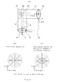
- Fig. 1 is a configuration view in which a system for determining partial discharge according to Embodiment 1 of the present invention is mounted on gas-insulated equipment.
- Fig. 2 is a cross-sectional configuration view seen from arrow direction of Q-Q shown in Fig. 1 .
- the gas-insulated equipment is configured such that a plurality of cylindrically shaped tanks 1 are coupled via insulating spacers 2 and a cylindrical center conductor 3 supported by the insulating spacers 2 is coaxially disposed with the tank 1. Then, insulating gas is filled in the tank 1 partitioned by the insulating spacers 2. Basically, as shown in Fig.
- an electromagnetic wave is generated by the partial discharge and propagated in the tank.
- the system for determining such a partial discharge is configured by focusing attention on a TE11 mode signal as a mode of the electromagnetic wave propagating along the coaxial tank structure as in Reference Examples.
- a TE11 mode signal as a mode of the electromagnetic wave propagating along the coaxial tank structure as in Reference Examples.
- an intensity distribution of electromagnetic waves in an outer circumferential direction of the tank 1, that is, an intensity distribution of outer circumferential electromagnetic waves in the insulating spacer 2 needs to be known at measurement.
- an electromagnetic wave detector 4 is movable along the outer circumferential direction of the insulating spacer 2 as in Reference Example 1, determination of partial discharge using the TE11 mode can be made by inputting an output of the electromagnetic wave detector 4 along the outer circumferential direction of the insulating spacer 2 to a determining section 7.
- reference numeral 5 denotes a moving device
- 6 denotes a displacement angle detector
- 12 denotes a guiding rail.
- the system for determining partial discharge has the electromagnetic wave detector 4 for detecting an electromagnetic wave signal, which propagates in the tank 1, at a plurality of outer circumferential positions of the insulating spacer 2; and a TE11 envelope detector 8 for extracting a signal of a frequency band in which the TE11 mode propagates but a TE21 mode does not propagate by utilizing a cutoff frequency. Further, the system for determining partial discharge has an intensity detector for detecting an intensity distribution of outer circumferential electromagnetic waves in the tank 1 from signal strength extracted with the TE11 envelope detector 8 and outer circumferential position information ⁇ of the electromagnetic wave detector 4. The intensity detector can be configured by a pattern recognition device 22 as described in Fig. 16 and Fig. 17 .
- a patterned output of the pattern recognition device 22 can be displayed in a detection pattern indicator 23 as a circular intensity distribution view such as shown in Fig. 15(c) of Fig. 15 , and Fig. 18(b) and Fig. 18(c) of Fig. 18 .
- an intensity distribution assumed at the other insulating spacer when a partial discharge occurs in the gas-insulated equipment to be observed for determination is patterned to display on the assumption pattern indicator 25, Therefore, the intensity distribution assumed at the other insulating spacer from such information when a partial discharge occurs in the gas-insulated equipment to be observed for determination is recorded in the assumption pattern indicator 25 as a case example.
- an intensity distribution at an insulating spacer 2d generated when a partial discharge occurs is recorded.
- display on the assumption pattern indicator 25 can be made as a circular intensity distribution view such as Fig. 15(c) of Fig.
- the insulating spacers 2c and 2d are respectively disposed behind and in front of the L shaped bent part with respect to the L shaped tanks 1c and 1d.
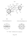
- a plane including axis lines of the tanks 1c and 1d is defined as a reference plane 15, The case where the partial discharge source 13 is located on the tank 1c side at the position which passes through the axis center in the direction (x-axis direction) parallel to the reference plane 15 will be described.
- FIG. 3(b) shows an intensity distribution of electromagnetic waves at one insulating spacer
- Fig. 3(c) shows an intensity distribution of electromagnetic waves at the other insulating spacer.
- Reference numeral 26 in Fig. 3(a) denotes an electric field relaxation shield for the post spacer 21.
- the post spacer 21 attached with the electric field relaxation shield is not a point-symmetric configuration centered on an axial point of the center conductor.
- a hand hole is provided at the bent part of the L shaped tank, and the post spacer 21 is mounted at the bent part of the L shaped tank through the hand hole to support the center conductor.
- the bent part of the L shaped tank is a portion where an extending tank I c and a tank 1d are intersected, and the bent part is a portion 27 surrounded by a dashed line shown in Fig. 3 .
- the inside structure information can be obtained, and when the structure is connected to the center conductor of the bent part 27 in parallel to the reference plane, and the above structure is not a point-symmetric configuration centered on an axial point of the center conductor; and when an intensity distribution having two peak values in a direction substantially parallel to the reference plane (x-axis direction or horizontal direction) at one insulating spacer is confirmed, and an intensity distribution having two peak values in a direction substantially parallel to the reference plane at the other insulating spacer is confirmed; it is determined that a partial discharge occurs in the L shaped tank.
- the assumption pattern indicator 25 displays the intensity distribution assumed at the other insulating spacer 2d when a partial discharge occurs as an assumption pattern (pattern shown in Fig. 18(c) ) by selecting from the recorded case example, from the information of the structure information output unit 24 and the intensity distribution information of the pattern recognition device 22.
- the intensity distribution is obtained with the pattern recognition device 22.
- This intensity distribution can be displayed by the detection pattern indicator 23.
- the patterned output of the pattern recognition device 22 is input to the determining device 11 to compare with the former assumption pattern of the assumption pattern indicator 25, and it can be determined whether or not a partial discharge occurs in the L shaped tank 1 by a matching degree between both patterns.
- a measurer can assume the intensity distribution assumed at the other insulating spacer 2d when a partial discharge occurs, from the intensity distribution information detected at one insulating spacer 2c and the inside structure information of the structure information output unit 24; and therefore, it can be determined whether or not a partial discharge exists in the gas-insulated equipment by comparing the assumed intensity distribution with the intensity distribution actually detected at the other insulating spacer 2d by the measurer.
- the measurer can know the structure information of the structure information output unit 24 by appearance without the outline structure information. The outline structure information is required when the determining device is automated.
- measurement sequence of the insulating spacer 2c pattern shown in Fig. 18(b)
- the insulating spacer 2d pattern shown in Fig. 18(c)
- the intensity distribution is obtained with the pattern recognition device 22.
- This intensity distribution can be displayed by the detection pattern indicator 23.
- the patterned output of the pattern recognition device 22 is input to the determining device 11 to compare with the former assumption pattern of the assumption pattern indicator 25, and it can be determined whether or not a partial discharge occurs in the L shaped tank 1 by a matching degree between both patterns.
- the measurer can assume the intensity distribution assumed at the other insulating spacer 2d when a partial discharge occurs, from the intensity distribution information detected at one insulating spacer 2c and the inside structure information of the structure information output unit 24; and therefore, it can be determined whether or not a partial discharge exists in the gas-insulated equipment by comparing the assumed intensity distribution with the intensity distribution actually detected at the other insulating spacer 2d by the measurer.
- the assumption pattern indicator 25 displays two intensity distributions assumed at the other insulating spacer 2d when a partial discharge occurs as assumption patterns (patterns shown in Fig. 3(c) and Fig. 18(c) ), from only the intensity distribution information of the pattern recognition device 22 because the information from the structure information output unit 24 is unknown.
- the intensity distribution can be displayed by the detection pattern indicator 23.
- the patterned output of the pattern recognition device 22 is input to the determining device 11 to compare with the former two assumption patterns of the assumption pattern indicator 25 respectively, and it can be determined whether or not a partial discharge occurs in the L shaped tank 1 by any of matching degrees.
- the measurer can assume two intensity distributions assumed at the other insulating spacer 2d when a partial discharge occurs, from the intensity distribution information detected at one insulating spacer 2c; and therefore, it can be determined whether or not partial discharge exists in the gas-insulated equipment by comparing any of the assumed two intensity distributions with the intensity distribution actually detected at the other insulating spacer 2d by the measurer.
- Embodiment 2 is different from Embodiment 1 in a position of providing a partial discharge source 13, and is an example when the partial discharge source 13 is generated on a tank 1c side in a direction (y-axis direction) perpendicular to a reference plane 15.
- a structure (post spacer) 21 is connected to a center conductor at a bent part 27 in parallel to the reference plane as in Fig. 3 , and the structure is not a point-symmetric configuration centered on an axial point of the center conductor.
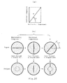
- Fig. 4(a) of Fig. 4 shows an occurrence position of the partial discharge in the L shaped tank;
- Fig. 4(b) shows an intensity distribution of electromagnetic waves at one insulating spacer;
- Fig. 4(c) shows an intensity distribution of electromagnetic waves at the other insulating spacer.
- an electromagnetic wave of a TE11 mode due to partial discharge observed at an insulating spacer 2c has a peak value in a direction (y-axis direction) perpendicular to the reference plane 15 as shown in Fig. 19(b) ; and even a signal observed at an insulating spacer 2d after passing the L shaped bent part, a signal distribution having a peak value in a direction perpendicular to the reference plane 15 is confirmed as shown in Fig. 19(c) .
- Fig. 4 verification has been made in the case where the post spacer 21 is connected to the center conductor at the bent part 27 in parallel to the reference plane, and the post spacer 21 is not a point-symmetric configuration centered on an axial point of the center conductor.
- electromagnetic waves due to partial discharge observed at an insulating spacer 2c have a peak value in a direction (y-axis direction) perpendicular to the reference plane 15 as shown in Fig. 4(b) ; and even a signal observed at an insulating spacer 2d after passing the L shaped bent part, a signal distribution having a peak value in a direction perpendicular to the reference plane 15 is confirmed as shown in Fig. 4(c) .
- Fig. 19(b) and Fig. 19(c) and Fig. 4(b) and Fig. 4(c) have substantially the same distribution.
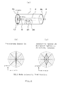
- a post spacer 21 for supporting a center conductor is mounted on the bottom surface side.
- the post spacer (structure) 21 is not a point-symmetric configuration centered on an axial point of the center conductor.
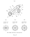
- Fig. 5 (a) of Fig. 5 shows an occurrence position of a partial discharge in the straight pipe tank;
- Fig. 5(b) shows an intensity distribution of electromagnetic waves at one insulating spacer;
- Fig. 5(c) shows an intensity distribution of electromagnetic waves at the other insulating spacer.
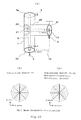
- the outline and inside structure information of gas-insulated equipment obtained from the structure information output unit is "a structure is connected to a center conductor at a branched part in a T-shaped tank in parallel to a reference plane, and the structure is not a point-symmetric configuration centered on an axial point of the center conductor, it is determined that a partial discharge occurs in the tank in the case where an intensity distribution having two peak values in a direction substantially parallel to the reference plane is confirmed at all the three insulating spacers.
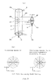
- Fig. 8 shows a case which is different from Fig. 7 in a position of providing the partial discharge source and there is the partial discharge source 13 located on one side of the straight pipe part of the T shaped tank in a direction (y-axis direction) perpendicular to the reference plane.
- Fig. 8(a) of Fig. 8 shows an occurrence position of a partial discharge in the T shaped tank;
- Fig. 8(b) shows an intensity distribution of electromagnetic waves at an insulating spacer 2e;
- Fig. 8(c) shows an intensity distribution of electromagnetic waves at an insulating spacer 2f; and
- Fig. 8(d) shows an intensity distribution of electromagnetic waves at an insulating spacer 2g.
- the outline and inside structure information obtained from the structure information output unit is "a structure is connected to a center conductor of a branched part in a T-shaped tank in parallel to a reference plane, and the structure is not a point-symmetric configuration centered on an axial point of the center conductor," it is determined that a partial discharge occurs in the tank in the case where an intensity distribution having two peak values in a direction substantially parallel to the reference plane is confirmed at all the three insulating spacers.
Landscapes
- Physics & Mathematics (AREA)
- General Physics & Mathematics (AREA)
- Testing Relating To Insulation (AREA)
- Installation Of Bus-Bars (AREA)
- Gas-Insulated Switchgears (AREA)
- Driving Mechanisms And Operating Circuits Of Arc-Extinguishing High-Tension Switches (AREA)
Abstract
Description
- The present invention relates to a method of determining partial discharge and a system for determining partial discharge for determining whether or not a partial discharge occurs in gas-insulated equipment.
- A method of determining partial discharge of known gas-insulated equipment is disclosed in a
non-patent document 1 by the inventors of the application concerned. This focuses attention on a TE11 mode in which a feature having a remarkable intensity distribution in an outer circumferential direction of an insulating spacer for particularly the gas-insulated equipment can be significantly used from higher TE modes on the basis of research results in which electromagnetic waves propagating in the gas-insulated equipment are analyzed and verified in detail in mode level; and this TE11 mode is set as a detection region.
Verification in which the presence of an electromagnetic wave in TE11 mode is certain is made by the remarkable outer circumferential intensity distribution of the insulating spacer of the gas-insulated equipment, and a mode change at the time when the electromagnetic wave in the aforementioned mode propagates in the gas-insulated equipment is also traced; and accordingly, it becomes possible to diagnose more surely and sophisticatedly. - In the known method disclosed in the
non-patent document 1, an electromagnetic wave generated in a tank due to partial discharge propagates in a metal tank, and the electromagnetic wave leaked outside is detected. This constructs a detecting method and a detecting system by assuming gas-insulated switchgear (referred to as GIS) as a simple straight pipe, L shaped, and T shaped structure, and by using a result in which an electric field intensity distribution in the gas-insulated equipment is verified in mode level.
However, in actual GINS, its shape is not simple, there exists a convex and concave structure such as a post spacer for supporting a center conductor and an electric field shield in the tank where electromagnetic waves propagate; and therefore, there is a case where a mode change generated at such area is different from a concept shown in theNon-Patent Document 1. Therefore, there is an apprehension that an erroneous determination is made in the actual equipment when determination is made by only the method disclosed in theNon-Patent Document 1. -
Patent document 1: Specification of Japanese Patent Application No. 2005-084305 filed on March 23, 2005 Non-patent document 1: S. Okabe Et al, "Method of diagnosing partial discharge using Electromagnetic wave mode conversion in GIS," the Journal of the Institute of Electrical Engineers of Japan (IEEJ) Transactions on Power and Energy 2005, Letter No. 331 - The present invention has been made to solve the problem described above, and an object of the present invention is to provide a method of determining partial discharge and a system for determining partial discharge with high accuracy adapted to more actual gas-insulated equipment while setting a TE11 mode in which a feature having a remarkable intensity distribution in an outer circumferential direction of an insulating spacer for particularly the gas-insulated equipment can be significantly used in a method of determining partial discharge and a system for determining partial discharge for tracing a mode change at the time when an electromagnetic wave propagates in the gas-insulated equipment, as a detection region; and while taking an actual internal construction of the gas-insulated equipment into account by further adding a verified result with respect to the internal construction of the gas-insulated equipment to research results in which electromagnetic waves propagating in the gas-insulated equipment are analyzed and verified in detail in mode level.
- A method of determining partial discharge according to the present invention, wherein as gas-insulated equipment, which is configured so that a cylindrical metal tank sealed with insulating gas is partitioned by insulating spacers and a center conductor is supported by the insulating spacers, is to be observed for determining the presence or absence of a partial discharge generated in the metal tank, the method includes the following steps:
- detecting an electromagnetic wave signal at a plurality of outer circumferential positions of the insulating spacer with an electromagnetic wave detector, the electromagnetic wave signal propagating in the mental tank;
- extracting a signal of a frequency band in which a TE11 mode propagates but a TE21 mode does not propagate by utilizing a cutoff frequency from the detected electromagnetic wave signal, with a TE11 envelope detector; and
- determining a partial discharge by detecting an intensity distribution of outer circumferential electromagnetic waves in the metal tank with an intensity detector from the intensity of the extracted signal with the TE11 envelope detector and the outer circumferential position information of the electromagnetic wave detector.
- Further, in the method of determining partial discharge according to the present invention, the metal tank has an L shaped bent part; and the metal tanks extending in two directions from the bent part are respectively provided with the insulating spacers. The method includes the step of determining that a partial discharge occurs in the L shaped metal tank when the outline and inside structure information of the gas-insulated equipment obtained from the structure information output unit defines a plane including axis lines of the L shaped metal tank as a reference plane and when a structure is connected to the center conductor at the bent part in parallel to the reference plane and the structure is not a point-symmetric configuration centered on an axial point of the center conductor and in the case where an intensity distribution having two peak values in a direction substantially parallel to the reference plane at one insulating spacer is confirmed and an intensity distribution having two peak values in a direction substantially parallel to the reference plane at the other insulating spacer is confirmed.
- Furthermore, a system for determining partial discharge according to the present invention is disclosed, wherein as gas-insulated equipment, which is configured so that a cylindrical metal tank sealed with insulating gas is partitioned by the insulating spacers and a center conductor is supported by the insulating spacers, is to be observed for determining the presence or absence of a partial discharge generated in the metal tank, wherein the system includes:
- an electromagnetic wave detector for detecting an electromagnetic wave signal at a plurality of outer circumferential positions of the insulating spacer, the electromagnetic wave signal propagating in the metal tank;
- a TE11 envelope detector for extracting a signal of a frequency band in which a TE11 mode propagates but a TE21 mode does not propagate by utilizing a cutoff frequency from the detected electromagnetic wave signal; and
- an intensity detector for detecting an intensity distribution of outer circumferential electromagnetic waves in the metal tank from the intensity of the extracted signal with the TE11 envelope detector and the outer circumferential position information of the electromagnetic wave detector. The system includes a structure information output unit which outputs inside structure information of the gas-insulated equipment.
- According to a method of determining partial discharge or a system for determining partial discharge of the present invention, a structure information output unit which outputs inside structure information of gas-insulated equipment is provided; and therefore, it can be specified with high accuracy whether or not a partial discharge exists in the gas-insulated equipment from an intensity distribution of outer circumferential electromagnetic waves in a metal tank detected with an intensity detector and the inside structure information of the structure information output unit.
In addition, according to a method of determining partial discharge or a system for determining partial discharge of the present invention, a structure information output unit which outputs outline and inside structure information of gas-insulated equipment is provided; and therefore, it can be specified with high accuracy whether or not a partial discharge exists in the gas-insulated equipment from an intensity distribution of outer circumferential electromagnetic waves in a metal tank detected with an intensity detector and the outline and inside structure information of the structure information output unit.
The foregoing and other objects, features, aspects and advantages of the present invention will become more apparent from the following detailed description of the present invention when taken in conjunction with the accompanying drawings. -
-
Fig. 1 is a configuration view in which a system for determining partial discharge according toEmbodiment 1 of the present invention is mounted on gas-insulated equipment. -
Fig. 2 is a cross-sectional configuration view seen from the arrow direction indicated by Q-Q as shown inFig. 1 . -
Fig. 3 is a view showing an intensity distribution of circumferential electromagnetic wave appeared when a partial discharge occurs in an L shaped tank according toEmbodiment 1. -
Fig. 4 is a view showing an intensity distribution of circumferential electromagnetic wave appeared when a partial discharge occurs in an L shaped tank according toEmbodiment 2. -
Fig. 5 is a view showing an intensity distribution of circumferential electromagnetic wave appeared when a partial discharge occurs in a straight pipe tank according toEmbodiment 3. -
-
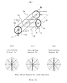
Fig. 6 is a view showing an intensity distribution of circumferential electromagnetic wave appeared when a partial discharge occurs in the straight pipe tank according toEmbodiment 3. -
Fig. 7 is a view showing an intensity distribution of circumferential electromagnetic wave appeared when a partial discharge occurs in a T shaped tank according toEmbodiment 4. -
Fig. 8 is a view showing an intensity distribution of circumferential electromagnetic wave appeared when a partial discharge occurs in the T shaped tank according toEmbodiment 4. -
Fig. 9 is a view showing an intensity distribution of circumferential electromagnetic wave appeared when a partial discharge occurs in a T shaped tank according toEmbodiment 5. -
Fig. 10 is a view showing an intensity distribution of circumferential electromagnetic wave appeared when a partial discharge occurs in the T shaped tank according toEmbodiment 5. -
-
Fig. 11 is a configuration view in which a system for determining partial discharge according to Reference Example 1 is mounted on gas-insulated equipment, -
Fig. 12 is a cross-sectional configuration view seen from the arrow direction indicated by P-P as shown inFig. 11 . -
Fig. 13 is a typical view showing an electromagnetic field distribution of a TEM mode, TE11 mode, and TE21 mode in a coaxial line. -
Fig. 14 is a view showing an example of an intensity distribution of electromagnetic wave when a partial discharge occurs in a tank. -
Fig. 15 is a view for explaining a method of determining partial discharge of a straight pipe tank according to Reference Example 1. -
Fig. 16 is a view showing another example of a determining section of the system for determining partial discharge ofFig. 11 . -
Fig. 17 is a view showing one example of an intensity distribution pattern obtained by the determining section ofFig. 16 . -
-
Fig. 18 is a view for explaining a method of determining partial discharge of an L shaped tank according to Reference Example 2. -
Fig. 19 is a view showing another example for explaining a method of determining partial discharge of the L shaped tank according to Reference Example 2. -
Fig. 20 is a view showing a further other example for explaining a method of determining partial discharge of the L shaped tank according to Reference Example 2. -
Fig. 21 is a view for explaining a method of determining partial discharge of a T shaped tank according to Reference Example 3. -
Fig. 22 is a view showing another example for explaining a method of determining partial discharge of the T shaped tank according to Reference Example 3. -
Fig. 23 is a view showing other example for explaining a method of determining partial discharge of the T shaped tank according to Reference Example 3. -
Fig. 24 is a view showing a further other example for explaining a method of determining partial discharge of the T shaped tank according to Reference Example 3. -
- 1
- = Metal tank
- 2
- = Insulating spacer
- 3
- = Center conductor
- 4
- = Electromagnetic wave detector
- 5
- = Moving device
- 6
- = Displacement angle detector
- 7
- = Determining section
- 8
- = TE11 envelope detector
- 9
- = Input section
- 10
- = Intensity detector
- 11
- = Determining device
- 12
- = Guiding rail
- 13
- = Partial discharge source
- 14
- = Pattern recognition device
- 15
- = Reference plane
- 16
- = Reference plane
- 21
- = Post spacer
- 22
- = Pattern recognition device
- 23
- = Detection pattern indicator
- 24
- = Structure information output unit
- 25
- = Assumption pattern indicator
- 26
- = Electric field relaxation shield
- 27
- = Bent part
- 28
- = Branched part
- As a previous step prior to explaining embodiments, the
patent document 1 which is an earlier application of the application concerned will be described in detail as reference examples. -
Fig. 11 is a configuration view in which a system for determining partial discharge according to Reference Example 1 is mounted on gas-insulated equipment. As an example of the gas-insulated equipment to be observed for determination, GIS (Gas Insulated Switchgear) will be described. GIS is configured so that it includes switchgear such as a disconnecting switch, a circuit breaker, and electrical equipment for protecting them, which are connected by bus lines, and a high voltage live part of each piece of equipment is accommodated in a metal tank filled with insulating gas. The Figure shows a case where the system for determining partial discharge is disposed in a bus line tank part of the GIS. - As shown in the Figure, the system is configured such that a plurality of cylindrically shaped
metal tanks 1 are coupled via insulatingspacers 2 and acylindrical center conductor 3 supported by the insulatingspacers 2 is coaxially disposed. Then, insulating gas is filled in themetal tank 1 partitioned by the insulatingspacers 2. In addition, a "metal tank" is referred to as merely a "tank" below. - Next, the configuration of the system for determining partial discharge will be described. An
electromagnetic wave detector 4 for detecting an electromagnetic wave signal which propagates in thetank 1 is disposed on an outer circumferential part of the insulatingspacer 2 which couples thetank 1. Theelectromagnetic wave detector 4 is mainly formed of an electromagnetic wave antenna, for example, a loop coil, a dipole antenna, a log periodic antenna, a horn antenna or the like.
Theelectromagnetic wave detector 4 is movable along the outer circumferential direction of the insulatingspacer 2 by a movingdevice 5, and an electromagnetic wave can be measured at any position in the outer circumferential direction to detect it. Position information of theelectromagnetic wave detector 4 when theelectromagnetic wave detector 4 is moved along the outer circumferential direction of the insulatingspacer 2 by the movingdevice 5 is sent to adisplacement angle detector 6 to be detected as a displacement angle θ from a reference point. - A detection signal from the
electromagnetic wave detector 4 and displacement angle information from thedisplacement angle detector 6 are transmitted to a determiningsection 7. The determiningsection 7 includes: - a
TE11 envelope detector 8 for extracting the electromagnetic wave signal of a frequency band in which a TE11 mode propagates but a TE21 mode does not propagate by utilizing a cutoff frequency, to be described later, from a detection signal of theelectromagnetic wave detector 4; - an
input section 9 for inputting outer diameter information of thetank 1 and thecenter conductor 3 necessary for computing the cutoff frequency; - an
intensity detector 10 for detecting an intensity distribution of electromagnetic waves in the outer circumferential direction of thetank 1 by receiving an output signal from theTE11 envelope detector 8 and the displacement angle θ of thedisplacement angle detector 6; and - a determining
device 11 for determining the presence or absence of a partial discharge by comparing the detected intensity distribution with an intensity distribution peculiar to the TE11 made. The above-mentionedreference numerals 4 to 11 constitute essential parts of the system for determining partial discharge. In addition, for example, a foreign particle or the like in the tank may act as apartial discharge source 13. -
Fig. 12 is a cross-sectional configuration view seen from arrow direction of P-P shown inFig. 11 and shows an example when theelectromagnetic wave detector 4 is made to move by the movingdevice 5. As shown in the Figure, a guidingrail 12 is provided on the outer circumferential part of the insulatingspacer 2 so as to slidably engage the guidingrail 12 with an engaging part provided on theelectromagnetic wave detector 4. A drive motor is provided on theelectromagnetic wave detector 4 so as to move on the guidingrail 12 by a command from the movingdevice 5. The position information in the circumferential direction at this time is extracted to thedisplacement angle detector 6. For example, if the position of the perpendicular bottom part of the Figure is the reference point, θ is detected as the displacement angle when measurement is performed at aposition 4a.
In addition, the moving device shown inFig. 12 is an example, and it is not limited to the configuration shown in the Figure as long as it can move in the outer circumferential direction of the insulatingspacer 2. - Next, a method for detecting partial discharge by the system for determining partial discharge will be described. The bus line tank of the GIS, as shown in
Fig. 11 , is of a coaxial structure composed of thecenter conductor 3 and thetank 1 which surrounds it. An electromagnetic wave mode which propagates in such a coaxial structure includes a TEM mode, a TE mode (TE11, TE21, TE31...), and a TM mode; each mode represents a different propagation form of electromagnetic waves and is distinguished by the presence or absence of an electric field and magnetic field vector with respect to the direction of propagation. It is known that the TEM, TE11 mode, TE21 mode... exist in limited areas not lower than a specific frequency for each mode.
Such a specific frequency is a so-called cutoff frequency and is determined according to the shape and size of configuration elements, such as the center conductor diameter, the tank diameter, or the like, that is, according to the shape and size of the gas-insulated equipment. For example, when the radius of thetank 1 is a, the radius of thecenter conductor 3 is b, and the velocity of light is c, the cutoff frequency f of the TEm1 mode is approximately represented by Equation (1).
where m = 1, 2, 3 ...
In other words, if the shapes of thetank 1 and thecenter conductor 3 are determined, an existing mode and the cutoff frequency can be specified. - Of the respective modes, the TEM mode is an electric field distribution that is the same as a static electric field that has no peak distribution in the circumferential direction of the tank. On the other hand, the TE(ml) mode denotes the electric field distribution that has a peak distribution in the circumferential direction.
Fig. 13 is a typical view showing the electromagnetic field distribution of the TEM mode, the TE11 mode, and the TE21 mode in a coaxial line. As shown in the Figure, the TE11 mode denotes an electric field distribution having strong peaks at circumferential positions of 180° symmetry; the TE21 mode denotes an electric field distribution having peaks at circumferential positions of 90° symmetry. -
Fig. 14 is a view showing an example of the intensity distribution of an electromagnetic wave when a partial discharge occurs in the tank. The contrast between the electromagnetic wave intensity of each frequency and the distribution state in the wall surface of the tank is represented in shading. This Figure is an example of experimental validation data cleared by investigation by the inventors, which shows a partial discharge generated in a tank with a 2 m long center conductor.
The vertical axis shows the outer circumferential position on the tank as an angle by defining the discharge source as a reference point (0°), and the horizontal axis shows frequency (MHz). In the Figure, parts in deep shade represent strong parts of the electromagnetic wave signal. Above the Figure, a frequency band in which each electromagnetic wave signal of the TEM mode, TE11 mode, TE21 mode, and TE31 mode propagates is shown by a horizontal bar chart. - As illustrated by circles in the Figure, it is well known that the TEM mode has signals uniformly in the circumferential direction without having a peak value; the TE11 mode has two strong peaks at the 180° opposing positions in the circumferential direction; and the TE21 mode has four peaks at intervals of 90°. Therefore, if such an intensity distribution is verified in the frequency region of each mode computed by using Equation (1), it indicates that there is absolutely an electromagnetic wave of its mode.
- As described above, electromagnetic waves due to partial discharge are broadly distributed in the GIS from the TEM region to that of mode signals of a higher order. It becomes possible to determine the presence or absence of a partial discharge in the GIS by obtaining the distribution shape. Here, a mode to be focused on needs to be determined by taking account of the ease of distinguishing the pattern and the ease of processing the signal. Regarding the ease of processing the signal, although it is preferable to select a lower frequency band as a detection target, it is difficult to find a characteristic distribution pattern because the TEM mode existing at the lowest frequency is distributed in all circumferential directions.
On the other hand, in the case of a higher order mode, since the shape of the distribution is complicated, it is possible to find a pattern peculiar to the GIS which does not exist in nature; however, if it is too complicated, the determining algorithm for the system for determining partial discharge becomes very sophisticated and complicated and processing of a high frequency signal also becomes difficult; thus it is not suitable for actual diagnosis.
Therefore, in this case, this example focuses on the TE11 mode, in which a feature relatively peculiar to the GIS can be found, and an area in which signal processing is easy. In addition, the frequency band of the TE11 mode for an actual GIS tank according to a trial calculation using Equation (1) is approximately 200 MHz to 1 GHz, though it differs according to the tank diameter. - The frequency band, which is previously described in that the electromagnetic wave signal of the frequency band in which the TE11 mode propagates but the TE21 mode does not propagate is extracted by utilizing a cutoff frequency with the
TE11 envelope detector 8 shown inFig. 11 , has a range not lower than the cutoff frequency of the TE11 mode calculated according to Equation (1) and less than the cutoff frequency of the TE21 mode.
In this regard, Equation (1) is an approximate equation and the mode cannot be completely distinguished by this equation, and therefore, the range need not to be strictly delimited and some tolerance may be provided at the front and back. For actual usage, it is practical to have some tolerance from the view point of versatility. - Next, a specific determining method in the gas-insulated equipment will be described.
Fig. 15 is a view for explaining a method of determining partial discharge using the system for determining partial discharge of Reference Example 1.Fig. 15(a) shows an occurrence position when a partial discharge occurs in thetank 1 formed of a straight pipe, which is partitioned by two insulatingspacers Fig. 15(b) is a cross-sectional view in a direction perpendicular to the z-axis of the occurrence position of the partial discharge and shows the case where thepartial discharge source 13 exists at a position at an angle θ when the horizontal direction is set as a reference, for example. Further,Fig. 15(c) shows the intensity distribution of an electromagnetic wave in the circumferential direction when the electromagnetic wave signal due to partial discharge is observed at the insulatingspacers straight pipe tank 1. - In addition, the
partial discharge source 13 is shown adjacent to the insulating spacer for the sake of facilitating understanding, but it may be placed at any location in thetank 1. Further, the intensity distribution of an electromagnetic wave signal is shown by simplifying in order to clearly visually describe the direction and shape that the peak mainly takes, and therefore, it does not correctly represent the actual measurement value.
The following description is also similar to the above description. Measurement of partial discharge is performed at a plurality of outer circumferential positions while theelectromagnetic wave detector 4 is moved by the movingdevice 5 along the outer circumferential direction of the insulatingspacer 2a. At this time, information of the measurement position from the reference point is detected by thedisplacement angle detector 6 as angle information θ, and transmitted to the determiningsection 7 of the system for determining partial discharge. - When the
partial discharge source 13 generated in the GIS tank exists, for example, at the position at the angle θ when the horizontal direction is set as the reference (13a opposing 13 by 180° is also the same), the electromagnetic wave signal is also strongly radiated in the direction of the angle θ; thus, in the insulatingspacer 2a, a distribution having a strong signal peak at substantially the angle θ is confirmed as shown inFig. 15(c) of the Figure.
Consequently, if the electromagnetic wave signal from theelectromagnetic wave detector 4, measured at a plurality of outer circumferential positions of the insulatingspacer 2a, is extracted to the determiningsection 7 of the system for determining partial discharge as shown inFig. 11 , to represent as an outer circumferential intensity distribution by performing signal processing, a strong peak value is found at the position opposing by substantially 180° when electromagnetic waves of the TE11 mode exist, that is, when the electromagnetic waves are due to partial discharge. Therefore, the presence or absence of a partial discharge can be determined depending on whether or not the intensity distribution of the detected result is indicative of a distribution peculiar to the TE11 mode. - A pattern recognition device, which is used as a specific example of the
intensity detector 10, will be described.Fig. 16 is a block diagram when apattern recognition device 14 is used as the intensity detector of the system for determining partial discharge shown inFig. 11 . Since the further components other than thepattern recognition device 14 are the same as inFig. 11 , their description will not be repeated.
When a TE11 signal from theTE11 envelope detector 8 and information of the displacement angle θ from thedisplacement angle detector 6 are input to thepattern recognition device 14, thepattern recognition device 14 generates an intensity distribution pattern of the electromagnetic wave signal on the outer circumference of the insulatingspacer 2.
An example of the intensity distribution pattern is shown inFig. 17 . The vertical axis of the Figure is the signal intensity, the horizontal axis is the circumferential position (angle), and the signal intensity at each position is graphed, resulting in an intensity distribution pattern shown by the thick line. The determiningdevice 11 determines, for example, whether or not a mode is peculiar to the TE11 mode from the interval between θ1 and θ2 and the peak values. - If remarkable peak values such as θ1 and θ2 are confirmed at positions substantially opposing each other by 180°, it can be determined that the distribution is peculiar to the TE11 mode, and therefore, it can be determined that the electromagnetic waves due to partial discharge are detected. As described, in the measurement in the outer circumferential direction of the insulating
spacer 2, it can be specified that there is no external noise but there exists a partial discharge inside by confirming, in a reproducible fashion, that two peaks exist at positions spaced by substantially 180°.
In addition, the pattern recognition device can use various kinds of signal processing techniques generally available at present. - Further, as shown in
Fig. 15(a) , in the case where the insulatingspacer 2a and the insulatingspacer 2b are disposed at both ends of thetank 1, when thepartial discharge source 13 exists in the insulated compartment, a distribution shape having two peaks, like that described above, propagates to both sides without losing its shape if a straight pipe tank is used; and therefore, the peak values appear at the same positions of the adjacent insulatingspacers
Consequently, in the case where two or more insulating spacers exist in thestraight pipe tank 1, when a signal of the TE11 mode having peaks at positions of 180° symmetry in the circumferential direction is detected and the peak values are confirmed at the same positions at the adjacent insulatingspacer 2b, the signal detected by theelectromagnetic wave detector 4 can be determined as a partial discharge signal in thetank 1. When the both peak positions are different, the signal is not being due to a partial discharge, but determined as external noise. - Further, as described above, the peak signal appears in the same direction as the circumferential position of the
partial discharge source 13. By using this fact, the circumferential position of thepartial discharge source 13 can be estimated by position (angle) information of the circumferential position of thetank 1 at which the detected peak signal appears. In this regard, inFig. 15(b) , it cannot be determined whether the partial discharge source appears at 13 or 13a, nor whether it appears at thetank 1 side or thecenter conductor 3 side.
The description so far concerns the case where, as a method of measuring at a plurality of outer circumferential positions of the insulatingspacer 2 using theelectromagnetic wave detector 4, the measurement position is moved by using the movingdevice 5. However, for example, a measurement operator may measure while moving theelectromagnetic wave detector 4 along the outer circumferential direction of the insulatingspacer 2 without depending on the movingdevice 5. Further, the position (angle) information need not be automatically extracted from thedisplacement angle detector 6; the measurement operator may input the information to theintensity detector 10. - Further, in order to compute the cutoff frequency, diameter information of the
tank 1 and thecenter conductor 3 is input from theinput section 9. However, the information need not be input in each case; but, it may be stored in advance in a memory unit, or a cutoff frequency computed from diameter information may be directly used when the gas-insulated equipment to be measured is specified.
Furthermore, when the presence or absence of a partial discharge is determined from the measurement result, at the stage where the intensity distribution is obtained by the intensity detector, it is possible, for a person of skill in the art, to determine the presence or absence of a partial discharge by observing the intensity distribution without using the determining device at a subsequent stage. For example, if the pattern recognition device described above is used as the intensity detector and the result is displayed visually as the intensity distribution pattern, the presence of the TE11 mode can be confirmed from the Figure. Therefore, the determiningdevice 11 in the determiningsection 7 is not required as the system for determining partial discharge. - As described above, according to Reference Example 1, the device performs: detecting an electromagnetic wave signal at a plurality of outer circumferential positions of an insulating spacer; extracting a signal of a frequency band in which a TE11 mode propagates but a TE21 mode does not propagate with a TE11 envelope detector; detecting an intensity distribution of an outer circumferential electromagnetic waves in a tank from the intensity of the extracted signal and the circumferential position information of an electromagnetic wave detector; and determining the presence or absence of a partial discharge depending on whether or not the intensity distribution is indicative of a distribution peculiar to the TE11 mode.
Therefore, a signal of the TE11 mode included in an electromagnetic wave caused by a partial discharge can be effectively captured and a feature peculiar to the mode can be extracted, thereby enabling the provision of a method of determining partial discharge or a system for determining partial discharge which can determine the presence or absence of a partial discharge with high reliability, without being affected by external noise.
Further, determination of the presence or absence of a partial discharge is performed by comparing the intensity distribution of the electromagnetic wave obtained by the intensity detector using the determining device with a distribution peculiar to the TE11 mode, and therefore, more accurate determination can be performed in addition to the above-mentioned effects. - Furthermore, intensity distributions of electromagnetic waves, respectively measured at two insulating spacers mounted in the axial direction of a straight pipe tank, are compared to determine that a partial discharge occurs in the straight pipe if peak positions of both intensity distributions are the same; therefore, the presence or absence of a partial discharge in the straight pipe tank can be accurately determined.
-
Fig. 18 to Fig. 20 are views for explaining a method of determining partial discharge according to Reference Example 2.Fig. 18(a) andFig. 19(a) show occurrence positions of partial discharges in an L shaped tank;Fig. 18(b) andFig. 19(b) show the intensity distributions of electromagnetic waves at an insulating spacer at one side; andFig. 18(c) andFig. 19(c) show the intensity distributions of electromagnetic waves at an insulating spacer at the other side.
As shown in the Figures, insulatingspacers tanks tanks Fig. 11 described in Reference Example 1, and the system for determining partial discharge is equivalent to the Figures described in Reference Example 1, a detailed description thereof will not be repeated, and a description mainly about the points of difference will be given. - In the case where the GIS is configured by a straight pipe tank, the behavior of the electromagnetic waves is simple as described in Reference Example 1; however, since an actual GIS is configured by combining a plurality of L shaped or T shaped tanks, conversion of the electromagnetic wave mode occurs at the L shaped or T shaped bent parts, and the shape of circumferential distribution of the signal is lost.
First, as shown inFig. 18 , the case where apartial discharge source 13 exists in thetank 1c at the front side of the L shaped bent part will be described. In order to specify a direction in the Figure, a plane including axis lines of thetanks reference plane 15. The case where thepartial discharge source 13 is located on thetank 1c side at a position which passes through the axis center in the direction (x-axis direction) parallel to thereference plane 15 will be described. - In this case, in the insulating
spacer 2c, the intensity distribution of the TE11 mode having a peak value in the direction (x-axis direction) parallel to thereference plane 15, likeFig. 18(b) of the Figure, is confirmed. Then, it is confirmed by investigation by the inventors that, in the insulatingspacer 2d after passing the L shaped part, the intensity distribution appeared in all the circumferential directions, as shown inFig. 18(c) of the Figure, unlike the distribution in 2c.
As a result, in the case where the insulatingspacers electromagnetic wave detector 4 at both insulatingspacers reference plane 15 at the insulatingspacer 2c on one side, it can be determined that a partial discharge, not external noise, occurs in the tank if it can be confirmed that the distribution reproducibly exists in all circumferential directions at the insulatingspacer 2d on the other side. Therefore, the presence or absence of a partial discharge occurred at a position parallel to the reference plane in the circumferential direction in the L shaped tank can be accurately determined. - Next is the case where the
partial discharge source 13 is located in thetank 1c at a position which passes through the axis center in the direction (y-axis direction) perpendicular to thereference plane 15, as shown inFig. 19(a) which is of the L shaped tank similar toFig. 18 . At this time, the electromagnetic waves of the TE11 mode due to the partial discharge observed at the insulatingspacer 2c have peak values in the direction (y-axis direction) perpendicular to thereference plane 15, as shown inFig. 19(b) of the Figure; as shown inFig. 19(c) of the Figure, a signal distribution having peak values in the direction perpendicular to thereference plane 15 is confirmed, even in a signal observed at the insulatingspacer 2d after passing the L shaped bent part. - From this result, in the case where the insulating
spacers tank electromagnetic wave detector 4 at both the insulating spacer parts, and two peak values exist in the direction substantially perpendicular to thereference plane 15 at the insulatingspacer 2c on one side, it can be determined that a partial discharge occurs in the tank if it can be confirmed that, similarly, two peak values reproducibly exist in the perpendicular direction at the insulatingspacer 2d on the other side.
Therefore, the presence or absence of a partial discharge occurred at a position perpendicular to the reference plane in the circumferential direction in the L shaped tank can be accurately determined. - The description so far is of the case where the partial discharge signal enters in the direction parallel or perpendicular to the
reference plane 15. Next, the case where thepartial discharge source 13 is located in a direction oblique to thereference plane 15 will be described. It is confirmed that, in the case where the signal enters in an oblique direction, the oblique signal is considered to be separated into a horizontal component and a vertical component and this will be described next. -
Fig. 20 is a view for explaining the variation of the TE11 mode electromagnetic wave distribution at the L shaped bent part when thepartial discharge source 13 exists in a direction oblique to the reference plane. As shown inFig. 20(a) of the Figure, in the case where thepartial discharge source 13 exists at a position of an angle θ with reference to a horizontal direction (the reference plane), a distribution having strong signal peaks is confirmed that thepartial discharge source 13 exists at a position of the angle θ as the sum of the horizontal component and the vertical component at the insulatingspacer 2c of themetal tank 1c side, as shown by "input" inFig. 20(b) of the Figure.
This can be considered as a result of the sum of the horizontal component (A cos θ) and the vertical component (A sin θ) into which the signal having amplitude A, entering at angle θ, is divided. On the other hand, at the insulatingspacer 2d side after passing the L shaped bent part, as shown by "output" inFig. 20(b) of the Figure, it is confirmed that a distribution like a bottom right mode, which is the sum of the result converted at respective bent parts of the horizontal component and the vertical component, appeared. - Consequently, in the actual measurement, in the case where outer circumferential distribution of the signal observed at the insulating spacers behind and in front of the L shaped bent part conforms to the distribution predicted here; that is, when an intensity distribution having two peak values in the oblique direction at the insulating spacer part on one side is confirmed, and an intensity distribution corresponding to the sum of the vertical direction component and the entire circumferential direction component is confirmed at the insulating spacer part on the other side, it can be determined that a partial discharge occurs in the tank. Therefore, the presence or absence of a partial discharge occurred at a position oblique to the reference plane in the circumferential direction in the L shaped tank can be accurately determined.
-
Fig. 21 to Fig. 24 are views for explaining a method of determining partial discharge according to Reference Example 3. Respective parts (a) of the Figures show occurrence positions where partial discharges in a T shaped tank; and parts (b) to (d) show the intensity distributions of electromagnetic waves at each insulating spacer. As shown in the Figures, the T shaped tank has a straight pipe part and a branch pipe part which is branched in a T shape in the middle of the straight pipe part and thetanks spacers Fig. 11 described in Reference Example 1, and the system for determining partial discharge is equivalent to the Figures described in Reference Example 1, a detailed description thereof will not be repeated, and a description mainly about the points of difference will be given. - In order to specify a direction in the Figure, a plane including axis lines of the
tanks 1e to 1g is set as areference plane 16. First, as shown inFig. 21 , the case where thepartial discharge source 13 is located on thetank 1e side at a position which passes through the tank axis center in a direction parallel to thereference plane 16 will be described. In the case where thepartial discharge source 13 exists at a position as shown in the Figure, the signal distribution of the TE11 mode having two peaks in the direction (x-axis direction) parallel to thereference plane 16 at the insulatingspacer 2e as shown inFig. 21(b) is confirmed.
At this time, it is noted that, in the insulatingspacer 2f on thebranch pipe 1f side and the insulatingspacer 2g on thestraight pipe 1g side after passing the branched part, the intensity distribution having substantially the same level appear in all circumferential directions, as shown inFig. 21(c) and Fig. 21(d) of the Figure, unlike the distribution in 2e. In addition, the case where thepartial discharge source 13 is located in the same direction on thestraight pipe 1g side is also similar. - On the other hand, as shown in
Fig. 22(a) , it is noted that when thepartial discharge source 13 exists in thebranch pipe 1f side at a position which passes through the axis center in a direction (z-axis direction) parallel to thereference plane 16, the distribution having two peak values parallel to the reference plane is confirmed at the insulatingspacer 2f as shown inFig. 22(b) ; in the insulatingspacer 2e on thestraight pipe 1e side and the insulatingspacer 2g on the straight pipe I g side after passing the branched part, the intensity distributions which have signals in the entire circumference in the circumferential direction appear, as shown inFig. 22(c) .
As a result, in the case where the T shaped tank is provided with insulating spacers on both sides of the straight pipe part and on the branch pipe side, and when the electromagnetic waves are detected with theelectromagnetic wave detector 4 at the respective insulatingspacers 2e to 2g to detect the frequency of the TE11 mode, which is deemed as the intensity distribution in the outer circumferential direction of the tank; it can be determined that a partial discharge occurs in the tank in the case where an intensity distribution having two peak values in a direction substantially parallel to thereference plane 16 at any one of the insulating spacer parts is confirmed and an intensity distribution having signals in the entire circumference at the other two insulating spacer parts is confirmed. Therefore, the presence or absence of a partial discharge occurred at a position parallel to the reference plane in the circumferential direction in the T shaped tank can be accurately determined. - Next, the case where the
partial discharge source 13 exists at a position which passes through the tank axis center in the direction (y-axis direction) perpendicular to thereference plane 16 will be described. This is the case where thepartial discharge source 13 is located in the direction perpendicular to thereference plane 16 at thestraight pipe 1e side of the T shaped tank as shown inFig. 23(a) .
In this case, in the insulatingspacer 2e on thetank 1e side at which thepartial discharge source 13 exists, the electromagnetic waves of the TE11 mode due to the partial discharge have two peak values in the direction perpendicular to thereference plane 16, as shown inFig. 23(b) ; further, as shown inFig. 23(c) and Fig. 23(d) , it is confirmed that the electromagnetic wave signals have the intensity distribution having two peak values in the direction perpendicular to thereference plane 16, even in the case of the insulatingspacer 2f on thebranch pipe 1f side and the insulatingspacer 2g on thestraight pipe 1g side after passing the branched part. - Similarly, as shown in
Fig. 24(a) , the case where thepartial discharge source 13 exists at a position which passes through the axis center on thebranch pipe 1f side in the direction perpendicular to thereference plane 16 will be described. In the insulatingspacer 2f on the metal tank side at which thepartial discharge source 13 exists, the electromagnetic waves of the TE11 mode due to the partial discharge have two peak values in the direction perpendicular to thereference plane 16, as shown inFig. 24(b) ; it is confirmed that the electromagnetic wave signal, observed at the insulatingspacers straight pipe reference plane 16, as shown inFig. 24(c) . - From these results, in the case where the insulating spacers are provided in three directions of the T shaped tank; when the electromagnetic wave signal detected with the
electromagnetic wave detector 4 at the respective insulatingspacers 2e to 2g is processed to obtain the intensity distribution in the outer circumferential direction of the tank, and two peak values in the direction substantially perpendicular to thereference plane 16 at either one of the insulating spacer parts exist; it is determined that a partial discharge occurs in the tank by confirming that two peak values reproducibly exist in the direction substantially perpendicular to thereference plane 16 similarly at the other insulating spacer parts, that is, by confirming that two peak values appears in the direction substantially perpendicular to thereference plane 16 at all the insulating spacer parts. Therefore, the presence or absence of a partial discharge occurred at a position perpendicular to the reference plane in the outer circumferential direction in the T shaped tank can be accurately determined. - For sake of simplicity, the description so far is of the case where the partial discharge source is located in the direction perpendicular or parallel to the
reference plane 16. In the case where the partial discharge source exists in the direction oblique with respect to thereference plane 16, as in the case described in Reference Example 2, the intensity distribution of the TE11 mode can be obtained by dividing the oblique direction signal into a horizontal component and a vertical component and by superimposing each mode conversion result again.
Although not shown in the Figure, in the case where thepartial discharge source 13 is located in a direction oblique with respect to thereference plane 16, it can be verified that an intensity distribution having two peak values in a direction substantially oblique with respect to thereference plane 16 at any one of three insulating spacer parts is confirmed and an intensity distribution corresponding to the sum of all circumferential direction components and a perpendicular direction component at the other two insulating spacer parts is confirmed.
Therefore, in the actual measurement, when the electromagnetic waves are detected with theelectromagnetic wave detector 4 at each insulating spacer part of the T shaped tank, the intensity distribution of the electromagnetic wave of the TE11 mode in the outer circumferential direction of each insulating spacer part is obtained by signal processing, and its result represents the intensity distribution as described above; it can be determined that a partial discharge occurs in the tank and those other than that are external noise. Therefore, the presence or absence of a partial discharge occurred at a position in an oblique direction to the reference plane in the circumferential direction in the T shaped tank can be accurately determined. -
Fig. 1 is a configuration view in which a system for determining partial discharge according toEmbodiment 1 of the present invention is mounted on gas-insulated equipment.Fig. 2 is a cross-sectional configuration view seen from arrow direction of Q-Q shown inFig. 1 . In respective Figures in the specification, the same reference numerals show identical or equivalent portions, and their description will be partly omitted.
The gas-insulated equipment is configured such that a plurality of cylindrically shapedtanks 1 are coupled via insulatingspacers 2 and acylindrical center conductor 3 supported by the insulatingspacers 2 is coaxially disposed with thetank 1. Then, insulating gas is filled in thetank 1 partitioned by the insulatingspacers 2. Basically, as shown inFig. 1 , GIS is of a coaxial structure composed of thecenter conductor 3 and thetank 1 that covers the center conductor; however, in some cases, a non-point symmetrically configuredpost spacer 21 centered on an axial point of thecenter conductor 3 is sometimes inserted to support thecenter conductor 3. Furthermore, an electric field shield is sometimes inserted. - When a partial discharge is generated in GIS, an electromagnetic wave is generated by the partial discharge and propagated in the tank. The system for determining such a partial discharge is configured by focusing attention on a TE11 mode signal as a mode of the electromagnetic wave propagating along the coaxial tank structure as in Reference Examples.
In order to determine a partial discharge by taking advantage of characteristics of the TE11 mode, an intensity distribution of electromagnetic waves in an outer circumferential direction of thetank 1, that is, an intensity distribution of outer circumferential electromagnetic waves in the insulatingspacer 2 needs to be known at measurement.
InFig. 1 , anelectromagnetic wave detector 4 is movable along the outer circumferential direction of the insulatingspacer 2 as in Reference Example 1, determination of partial discharge using the TE11 mode can be made by inputting an output of theelectromagnetic wave detector 4 along the outer circumferential direction of the insulatingspacer 2 to a determiningsection 7. In addition,reference numeral 5 denotes a moving device, 6 denotes a displacement angle detector, and 12 denotes a guiding rail. - The system for determining partial discharge has the
electromagnetic wave detector 4 for detecting an electromagnetic wave signal, which propagates in thetank 1, at a plurality of outer circumferential positions of the insulatingspacer 2; and aTE11 envelope detector 8 for extracting a signal of a frequency band in which the TE11 mode propagates but a TE21 mode does not propagate by utilizing a cutoff frequency.
Further, the system for determining partial discharge has an intensity detector for detecting an intensity distribution of outer circumferential electromagnetic waves in thetank 1 from signal strength extracted with theTE11 envelope detector 8 and outer circumferential position information θ of theelectromagnetic wave detector 4. The intensity detector can be configured by apattern recognition device 22 as described inFig. 16 and Fig. 17 . A patterned output of thepattern recognition device 22 can be displayed in adetection pattern indicator 23 as a circular intensity distribution view such as shown inFig. 15(c) ofFig. 15 , andFig. 18(b) and Fig. 18(c) ofFig. 18 . - Outline and inside structure information of the gas-insulated equipment to be observed for determination is input to a structure
information output unit 24 and stored therein. Information such as a straight pipe tank, an L shaped tank, and a T shaped tank of the gas-insulated equipment to be observed for determination is included as the outline structure information to be stored in the a structureinformation output unit 24; and positions of the insulating spacers in each tank may be incorporated.
The presence or absence of the post spacer and the electric field shield in the gas-insulated equipment to be observed for determination, mounting positions thereof, mounting directions, shapes, and the like are included as the inside structure information to be stored in the structureinformation output unit 24. Anassumption pattern indicator 25 obtains intensity distribution information detected at one of the insulating spacers in the gas-insulated equipment to be observed for determination from thepattern recognition device 22, and obtains the outline and inside structure information from the structureinformation output unit 24. - From such information, an intensity distribution assumed at the other insulating spacer when a partial discharge occurs in the gas-insulated equipment to be observed for determination is patterned to display on the
assumption pattern indicator 25, Therefore, the intensity distribution assumed at the other insulating spacer from such information when a partial discharge occurs in the gas-insulated equipment to be observed for determination is recorded in theassumption pattern indicator 25 as a case example.
For example, an intensity distribution at an insulatingspacer 2d generated when a partial discharge occurs, the intensity distribution being assumed from the outline and inside structure information and the intensity distribution information at an insulatingspacer 2c which are to be described later inFig. 3 , is recorded. In addition, display on theassumption pattern indicator 25 can be made as a circular intensity distribution view such asFig. 15(c) ofFig. 15 andFig. 18(b) and Fig. 18(c) ofFig. 18 . In addition, furthermore, only the outline and inside structure information of the structureinformation output unit 24 can be displayed on theassumption pattern indicator 25.
A determiningdevice 11 compares the output patterned by thepattern recognition device 22 with the patterned output assumed by theassumption pattern indicator 25 on the basis of the intensity distribution actually detected at the other insulating spacer; and the presence or absence of the partial discharge generated in the gas-insulated equipment to be observed for determination is determined by a matching degree. - The case where the thus configured system for determining partial discharge is applied to measurement of the L shaped tank will be described. Referring to Reference Example 2 and
Fig. 18 , the insulatingspacers tanks tanks reference plane 15, The case where thepartial discharge source 13 is located on thetank 1c side at the position which passes through the axis center in the direction (x-axis direction) parallel to thereference plane 15 will be described. - When the electromagnetic wave propagates in the tank, in the case of passing through the L shaped bent part, conversion of the electromagnetic wave mode occurs at the bent part, and the shape of circumferential distribution of the signal is lost as described in Reference Example 2. In this case, as shown in
Fig. 18 , the intensity distribution of the TE11 mode having a peak value in the direction (x-axis direction) substantially parallel to thereference plane 15 in the insulatingspacer 2c likeFig. 18(b) ofFig. 18 is confirmed. Then, in the insulatingspacer 2d after passing the L shaped bent part, the intensity distribution appears in the all circumferential directions, as shown inFig. 18(c) ofFig. 18 , unlike the distribution in 2c. - However, with respect to the distribution of the TE11 mode having a peak value in the direction (x-axis direction) substantially parallel to the
reference plane 15, as only onepost spacer 21 shown inFig. 3(a) ofFig. 3 , in the case where a structure is connected to the center conductor at the bent part in parallel to the reference plane and the structure is not a point-symmetric configuration centered on an axial point of the center conductor, it has been noted that there appears a mode change different fromFig. 18(c) ofFig. 18 as shown inFig. 3(c) ofFig. 3 .
In addition,Fig. 3(a) ofFig. 3 shows an occurrence position of a partial discharge in an L shaped tank when there is the post spacer;Fig. 3(b) shows an intensity distribution of electromagnetic waves at one insulating spacer; andFig. 3(c) shows an intensity distribution of electromagnetic waves at the other insulating spacer.
Reference numeral 26 inFig. 3(a) denotes an electric field relaxation shield for thepost spacer 21. Thepost spacer 21 attached with the electric field relaxation shield is not a point-symmetric configuration centered on an axial point of the center conductor. There is a case where a hand hole is provided at the bent part of the L shaped tank, and thepost spacer 21 is mounted at the bent part of the L shaped tank through the hand hole to support the center conductor. In addition, the bent part of the L shaped tank is a portion where an extending tank I c and atank 1d are intersected, and the bent part is aportion 27 surrounded by a dashed line shown inFig. 3 . - When a signal having a peak value in the direction (x-axis direction) substantially parallel to the
reference plane 15 comes into the L shaped bent part, a signal transmission path deviates toward only one side because the structure is not a point-symmetry centered on an axial point with respect to a direction having its signal distribution, but the structure exists on only one side. Therefore, it is finally considered to be an influence on a distribution in the insulatingspacer 2d, and a distribution having a peak value in a direction substantially parallel to thereference plane 15 is prominently observed. - As described, in the case where the structure is connected to the center conductor at the bent part in parallel to the above reference plane so as to overlap with the signal intensity distribution, and the above structure is not a point-symmetric configuration centered on an axial point of the center conductor; and when an intensity distribution having two peak values in a direction substantially parallel to the above reference plane at one insulating spacer is confirmed, and an intensity distribution having two peak values in a direction substantially parallel to the above reference plane at the other insulating spacer is confirmed; it can be determined that a partial discharge occurs in the L shaped tank.
- As a specific determining method, when the inside structure information can be obtained, and when a non-point-symmetric structure centered on an axial point of the center conductor is not located at the
bent part 27; and when an intensity distribution having two peak values in a direction substantially parallel to the reference plane (x-axis direction or horizontal direction) at one insulating spacer is confirmed, and an intensity distribution having substantially the same level in the entire circumference at the other insulating spacer is confirmed; it is determined that a partial discharge occurs in the L shaped tank.
On the other hand, when the inside structure information can be obtained, and when the structure is connected to the center conductor of thebent part 27 in parallel to the reference plane, and the above structure is not a point-symmetric configuration centered on an axial point of the center conductor; and when an intensity distribution having two peak values in a direction substantially parallel to the reference plane (x-axis direction or horizontal direction) at one insulating spacer is confirmed, and an intensity distribution having two peak values in a direction substantially parallel to the reference plane at the other insulating spacer is confirmed; it is determined that a partial discharge occurs in the L shaped tank. - In addition, when the inside structure information cannot be obtained (when the inside structure information is unknown), and when an intensity distribution having two peak values in a direction substantially parallel to the reference plane at one insulating spacer is confirmed, and an intensity distribution having two peak values in a direction substantially parallel to the reference plane at the other insulating spacer is confirmed, or an intensity distribution having substantially the same level in the entire circumference at the other insulating spacer is confirmed; it is determined that a partial discharge occurs in the L shaped tank.
- The description will be made by applying the above specific determining method to the system for determining partial discharge shown in
Fig. 1 . "A non-point-symmetric structure centered on an axial point of a center conductor is not located at a bent part in an L shaped tank" is input and stored in the structureinformation output unit 24 as the outline and inside structure information. The information in the structureinformation output unit 24 can also be displayed on theassumption pattern indicator 25. In this case, measurement is made at one insulatingspacer 2c (Fig. 18(a) ), and the intensity distribution having two peak values substantially parallel to the reference plane is confirmed (Fig. 18(b) ).
This confirmation information is displayed on thedetection pattern indicator 23 as an output of thepattern recognition device 22. Theassumption pattern indicator 25 displays the intensity distribution assumed at the other insulatingspacer 2d when a partial discharge occurs as an assumption pattern (pattern shown inFig. 18(c) ) by selecting from the recorded case example, from the information of the structureinformation output unit 24 and the intensity distribution information of thepattern recognition device 22. - Subsequently, measurement is actually made at the other insulating
spacer 2d, and the intensity distribution is obtained with thepattern recognition device 22. This intensity distribution can be displayed by thedetection pattern indicator 23. The patterned output of thepattern recognition device 22 is input to the determiningdevice 11 to compare with the former assumption pattern of theassumption pattern indicator 25, and it can be determined whether or not a partial discharge occurs in the L shapedtank 1 by a matching degree between both patterns.
In addition, even when there is no such determiningdevice 11, a measurer can assume the intensity distribution assumed at the other insulatingspacer 2d when a partial discharge occurs, from the intensity distribution information detected at one insulatingspacer 2c and the inside structure information of the structureinformation output unit 24; and therefore, it can be determined whether or not a partial discharge exists in the gas-insulated equipment by comparing the assumed intensity distribution with the intensity distribution actually detected at the other insulatingspacer 2d by the measurer. In addition, furthermore, if there is the inside structure information, the measurer can know the structure information of the structureinformation output unit 24 by appearance without the outline structure information. The outline structure information is required when the determining device is automated.
Furthermore, even measurement sequence of the insulatingspacer 2c (pattern shown inFig. 18(b) ) and the insulatingspacer 2d (pattern shown inFig. 18(c) ) is reversed, determination can be made in the same way. - Next, "a structure is connected to a center conductor at a bent part in an L shaped tank in parallel to a reference plane, and there is the structure which is not a point-symmetry centered on an axial point of the center conductor" is input and stored in the structure
information output unit 24 as the outline and inside structure information. In this case, measurement is made at one insulatingspacer 2c, and the intensity distribution having two peak values substantially parallel to the reference plane is confirmed (Fig. 3(b) ).
This confirmation information is displayed on thedetection pattern indicator 23 as an output of thepattern recognition device 22. Theassumption pattern indicator 25 displays the intensity distribution assumed at the other insulatingspacer 2d when a partial discharge occurs as an assumption pattern (pattern shown inFig. 3(c) ), from the information of the structureinformation output unit 24 and the intensity distribution information of thepattern recognition device 22. - Subsequently, measurement is actually made at the other insulating
spacer 2d, and the intensity distribution is obtained with thepattern recognition device 22. This intensity distribution can be displayed by thedetection pattern indicator 23. The patterned output of thepattern recognition device 22 is input to the determiningdevice 11 to compare with the former assumption pattern of theassumption pattern indicator 25, and it can be determined whether or not a partial discharge occurs in the L shapedtank 1 by a matching degree between both patterns.
In addition, even in this case, when there is no such determiningdevice 11, the measurer can assume the intensity distribution assumed at the other insulatingspacer 2d when a partial discharge occurs, from the intensity distribution information detected at one insulatingspacer 2c and the inside structure information of the structureinformation output unit 24; and therefore, it can be determined whether or not a partial discharge exists in the gas-insulated equipment by comparing the assumed intensity distribution with the intensity distribution actually detected at the other insulatingspacer 2d by the measurer. - In addition, there is a case when the inside structure information of the tank is unknown. Even in this case, measurement is made at one insulating
spacer 2c, and the intensity distribution having two peak values substantially parallel to the reference plane (horizontal direction) is confirmed (Fig. 3(b) ). This confirmation information is displayed on thedetection pattern indicator 23 as an output of thepattern recognition device 22.
Theassumption pattern indicator 25 displays two intensity distributions assumed at the other insulatingspacer 2d when a partial discharge occurs as assumption patterns (patterns shown inFig. 3(c) andFig. 18(c) ), from only the intensity distribution information of thepattern recognition device 22 because the information from the structureinformation output unit 24 is unknown. - Subsequently, measurement is actually made at the other insulating
spacer 2d, and the intensity distribution is obtained with thepattern recognition device 22. This intensity distribution can be displayed by thedetection pattern indicator 23. The patterned output of thepattern recognition device 22 is input to the determiningdevice 11 to compare with the former two assumption patterns of theassumption pattern indicator 25 respectively, and it can be determined whether or not a partial discharge occurs in the L shapedtank 1 by any of matching degrees.
In addition, even in this case, also when there is no such determiningdevice 11, the measurer can assume two intensity distributions assumed at the other insulatingspacer 2d when a partial discharge occurs, from the intensity distribution information detected at one insulatingspacer 2c; and therefore, it can be determined whether or not partial discharge exists in the gas-insulated equipment by comparing any of the assumed two intensity distributions with the intensity distribution actually detected at the other insulatingspacer 2d by the measurer. -
Embodiment 2 is different fromEmbodiment 1 in a position of providing apartial discharge source 13, and is an example when thepartial discharge source 13 is generated on atank 1c side in a direction (y-axis direction) perpendicular to areference plane 15. In an L shapedtank 1, a structure (post spacer) 21 is connected to a center conductor at abent part 27 in parallel to the reference plane as inFig. 3 , and the structure is not a point-symmetric configuration centered on an axial point of the center conductor.Fig. 4(a) ofFig. 4 shows an occurrence position of the partial discharge in the L shaped tank;Fig. 4(b) shows an intensity distribution of electromagnetic waves at one insulating spacer; andFig. 4(c) shows an intensity distribution of electromagnetic waves at the other insulating spacer. - When there is no
such post spacer 21, as shown inFig. 19 of Reference Example 2, an electromagnetic wave of a TE11 mode due to partial discharge observed at an insulatingspacer 2c has a peak value in a direction (y-axis direction) perpendicular to thereference plane 15 as shown inFig. 19(b) ; and even a signal observed at an insulatingspacer 2d after passing the L shaped bent part, a signal distribution having a peak value in a direction perpendicular to thereference plane 15 is confirmed as shown inFig. 19(c) . - On the other hand, as shown in
Fig. 4 , verification has been made in the case where thepost spacer 21 is connected to the center conductor at thebent part 27 in parallel to the reference plane, and thepost spacer 21 is not a point-symmetric configuration centered on an axial point of the center conductor. According to the verification, electromagnetic waves due to partial discharge observed at an insulatingspacer 2c have a peak value in a direction (y-axis direction) perpendicular to thereference plane 15 as shown inFig. 4(b) ; and even a signal observed at an insulatingspacer 2d after passing the L shaped bent part, a signal distribution having a peak value in a direction perpendicular to thereference plane 15 is confirmed as shown inFig. 4(c) .
As a result, in a determining concept simply focused on the peak, it may be said thatFig. 19(b) and Fig. 19(c) andFig. 4(b) and Fig. 4(c) have substantially the same distribution. - Verification has been made in the case where a post spacer is mounted in a straight pipe tank and a T shaped tank other than an L shaped tank.
Embodiment 3 is an example where the post spacer is mounted in the straight pipe tank. As shown inFig. 5 , apost spacer 21 for supporting a center conductor is mounted on the bottom surface side. The post spacer (structure) 21 is not a point-symmetric configuration centered on an axial point of the center conductor.Fig. 5 (a) ofFig. 5 shows an occurrence position of a partial discharge in the straight pipe tank;Fig. 5(b) shows an intensity distribution of electromagnetic waves at one insulating spacer; andFig. 5(c) shows an intensity distribution of electromagnetic waves at the other insulating spacer. - As described in
Fig. 15 of Reference Example 1, when there is nosuch post spacer 21, and when a partial discharge occurs in a horizontal direction (x-axis direction), two peaks of electromagnetic waves are observed in the horizontal direction at both insulatingspacers post spacer 21 is mounted as shown inFig. 5 , and when a partial discharge occurs in a horizontal direction (x-axis direction), two peaks are observed in the horizontal direction at both insulatingspacers post spacer 21 is changed. Therefore, its tendency is not changed irrespective of the presence or absence of the structure, and the same determining algorithm is realized. - On the other hand, when a partial discharge occurs in a vertical direction (y-axis direction), and when there exists a non-point-symmetric structure (post spacer) 21 with respect to a center conductor axis on the bottom surface side, two peaks are observed in the vertical direction in an intensity distribution of electromagnetic waves measured at the insulating
spacer 2a as shown inFig. 6(b) . As shown inFig. 6(c) , a pattern shape of the electromagnetic waves measured at the insulatingspacer 2b is lost, and components other than the vertical direction increase; however, it is not largely changed in that two peaks are observed in the vertical direction.
This is the same even the axial position of the center conductor at thestructure 21 is changed. Therefore, it is possible to determine the presence or absence of the partial discharge with high accuracy by knowing these phenomena. In addition,Fig. 6(a) ofFig. 6 shows an occurrence position of a partial discharge in the straight pipe tank;Fig. 6(b) shows an intensity distribution of electromagnetic waves at one insulating spacer; andFig. 6(c) shows an intensity distribution of electromagnetic waves at the other insulating spacer. -
Embodiment 4 is an example in which a post spacer is mounted in a T shaped tank. The T shaped tank has a straight pipe part and a branch pipe part which is branched in a T shape in the middle of the straight pipe part; and the above tanks extending in three directions from a branched part are respectively provided with insulating spacers. When a plane including axis lines (an axis line of the straight pipe part and an axis line of the branch pipe part) of the T shaped tank is defined as a reference plane, a structure (post spacer) is connected to a center conductor at the branched part in parallel to the reference plane, and the above structure is not a point-symmetric configuration centered on an axial point of the center conductor.
There is a case where a hand hole is provided at the branched part of the T shaped tank, and the post spacer is mounted at the branched part of the T shaped tank through the hand hole to support the center conductor. In addition, the branched part of the T shaped tank is a portion where the extending straight pipe tank and the branch pipe tank are intersected, and the branched part is aportion 28 surrounded by a dashed line shown inFig. 7 . -
Fig. 7 shows a case where there is apartial discharge source 13 located on one side of the straight pipe part of the T shaped tank in a direction (x-axis direction or horizontal direction) passing through the axis center and parallel to thereference plane 16.Fig. 7(a) ofFig. 7 shows an occurrence position of a partial discharge in the T shaped tank;Fig. 7(b) shows an intensity distribution of electromagnetic waves at an insulatingspacer 2e;Fig. 7(c) shows an intensity distribution of electromagnetic waves at an insulating spacer 2f; andFig. 7(d) shows an intensity distribution of electromagnetic waves at an insulatingspacer 2g. - When there is no
such post spacer 21, as shown inFig. 21 of Reference Example 3, two peaks of electromagnetic waves are observed in substantially parallel to the reference plane at the insulating spacer 2e; and intensity distributions having substantially the same level in the entire circumference are observed at both insulatingspacers
On the other hand, when the structure (post spacer) 21 is connected to the center conductor at thebranched part 28 in parallel to the reference plane, and the structure is not a point-symmetric configuration centered on an axial point of the center conductor, an intensity distribution having two peak values in a horizontal direction at the insulatingspacer 2e is confirmed.
Intensity distributions broadening in a vertical direction (y-axis direction) and having two peak values in a horizontal direction are confirmed at the insulatingspacers information output unit 24 as outline and inside structure information. - As described, in the T shaped tank, when the outline and inside structure information of gas-insulated equipment obtained from the structure information output unit is "a structure is connected to a center conductor at a branched part in a T-shaped tank in parallel to a reference plane, and the structure is not a point-symmetric configuration centered on an axial point of the center conductor, it is determined that a partial discharge occurs in the tank in the case where an intensity distribution having two peak values in a direction substantially parallel to the reference plane is confirmed at all the three insulating spacers.
-
Fig. 8 shows a case which is different fromFig. 7 in a position of providing the partial discharge source and there is thepartial discharge source 13 located on one side of the straight pipe part of the T shaped tank in a direction (y-axis direction) perpendicular to the reference plane.Fig. 8(a) ofFig. 8 shows an occurrence position of a partial discharge in the T shaped tank;Fig. 8(b) shows an intensity distribution of electromagnetic waves at an insulatingspacer 2e;Fig. 8(c) shows an intensity distribution of electromagnetic waves at an insulating spacer 2f; andFig. 8(d) shows an intensity distribution of electromagnetic waves at an insulatingspacer 2g. - When there is no
such post spacer 21 , as shown inFig. 23 of Reference Example 3, two peaks of electromagnetic waves are observed in the vertical direction at all the insulatingspacers
On the other hand, even in the case where the structure (post spacer) 21 is connected to the center conductor at thebranched part 28 in the T shaped tank in parallel to the reference plane, and the structure is not a point-symmetric configuration centered on an axial point of the center conductor, two peaks of electromagnetic waves are observed in the vertical direction at all the insulatingspacers Fig. 8(b), Fig. 8(c), and Fig. 8(d) . Therefore, its tendency is not changed irrespective of the presence or absence of the structure, and the same determining algorithm is realized. -
Embodiment 5 is different fromEmbodiment 4 in a position of providing apartial discharge source 13, and is an example when thepartial discharge source 13 is generated on a branch pipe part side. A structure (post spacer) is connected to a center conductor at abranched part 28 in a T shaped tank in parallel to a reference plane, and the structure is not a point-symmetric configuration centered on an axial point of the center conductor as inEmbodiment 4.
Fig. 9 shows a case where thepartial discharge source 13 is generated in a direction (x-axis direction) passing through the axis center and substantially parallel to thereference plane 16.Fig. 9(a) ofFig. 9 shows an occurrence position of a partial discharge in the T shaped tank;Fig. 9(b) shows an intensity distribution of electromagnetic waves at an insulating spacer 2f; andFig. 9(c) shows an intensity distribution of electromagnetic waves at insulatingspacers - When there is no
such post spacer 21, as shown inFig. 22 of Reference Example 3, two peaks of electromagnetic waves are observed in substantially parallel to the reference plane at the insulating spacer 2f; and intensity distributions having substantially the same level in the entire circumference are observed at both insulatingspacers
On the other hand, when the structure (post spacer) 21 is connected to the center conductor at thebranched part 28 in parallel to the reference plane, and the structure is not a point-symmetric configuration centered on an axial point of the center conductor, an intensity distribution having two peak values in a direction substantially parallel to the reference plane at the insulatingspacer 2f is confirmed.
Intensity distributions broadening in a direction (y-axis direction) perpendicular to the reference plane and having two peak values in a direction parallel to the reference plane are confirmed at the insulatingspacers information output unit 24 as outline and inside structure information. - As described, in the T shaped tank, when the outline and inside structure information obtained from the structure information output unit is "a structure is connected to a center conductor of a branched part in a T-shaped tank in parallel to a reference plane, and the structure is not a point-symmetric configuration centered on an axial point of the center conductor," it is determined that a partial discharge occurs in the tank in the case where an intensity distribution having two peak values in a direction substantially parallel to the reference plane is confirmed at all the three insulating spacers.
-
Fig. 10 shows a case which is different fromFig. 9 in a position of providing the partial discharge source and thepartial discharge source 13 is generated on the branch pipe part side of the T shaped tank in a direction (y-axis direction) substantially perpendicular to thereference plane 16.Fig. 10(a) ofFig. 10 shows an occurrence position of a partial discharge in the T shaped tank;Fig. 10(b) shows an intensity distribution of electromagnetic waves at the insulating spacer 2f; andFig. 10(c) shows intensity distributions of electromagnetic waves at the insulatingspacers - When there is no
such post spacer 21, as shown inFig. 24 of Reference Example 3, two peaks of electromagnetic waves are observed in the vertical direction at all the insulatingspacers
On the other hand, even in the case where the structure (post spacer) 21 is connected to the center conductor at thebranched part 28 in the T shaped tank in parallel to the reference plane, and the structure is not a point-symmetric configuration centered on an axial point of the center conductor, two peaks of electromagnetic waves are observed in the vertical direction at all the insulatingspacers Figs. 10(b) and Fig. 10(c) . Therefore, its tendency is not changed irrespective of the presence or absence of the structure, and the same determining algorithm is realized. - As described above, the post spacer attached with the electric field relaxation shield mounted in gas-insulated equipment is one which is generally used in the gas-insulated equipment. It is possible to increase in accuracy of determination at the time when a partial discharge occurs by knowing an intensity distribution of electromagnetic waves at each insulating spacer assumed during occurring of the partial discharge when the post spacer is mounted in the gas-insulated equipment as a case example, or by storing the same in an assumption pattern indicator.
Further, it is possible to increase in accuracy of determination at the time when a partial discharge occurs by accumulating case examples of structure information and intensity distributions at respective insulating spacers during occurring of the partial discharge with respect to other structures mounted in the gas-insulated equipment, and by knowing or recording the structure information and the intensity distributions at respective insulating spacers during occurring of the partial discharge with respect to such accumulated case examples.
While the presently preferred embodiments of the present invention have been shown and described. It is to be understood that these disclosures are for the purpose of illustration and that various changes and modifications may be made without departing from the scope of the invention as set forth in the appended claims.
Claims (8)
- A method of determining partial discharge, wherein as gas-insulated equipment, which is configured so that a cylindrical metal tank sealed with insulating gas is partitioned by insulating spacers and a center conductor is supported by the insulating spacers, is to be observed for determining the presence or absence of a partial discharge generated in the metal tank, the method including the steps of: detecting an electromagnetic wave signal at a plurality of outer circumferential positions of the insulating spacer with an electromagnetic wave detector, the electromagnetic wave signal propagating in the metal tank; extracting a signal of a frequency band in which a TE11 mode propagates but a TE21 mode does not propagate by utilizing a cutoff frequency from the detected electromagnetic wave signal, with a TE11 envelope detector;and determining a partial discharge by detecting an intensity distribution of outer circumferential electromagnetic waves in the metal tank with an intensity detector from the intensity of the extracted signal with the TE11 envelope detector and the outer circumferential position information of theelectromagnetic wave detector, the method comprising:- a structure information output unit which outputs inside structure information of the gas-insulated equipment; and- the step of determining the presence or absence of a partial discharge from the intensity distribution of the outer circumferential electromagnetic waves in the metal tank detected with the intensity detector and the inside structure information of the structure information output unit.
- The method of determining partial discharge according to claim 1, further comprising:- a structure information output unit which outputs outline and inside structure information of the gas-insulated equipment; and- the step of determining the presence or absence of a partial discharge from the intensity distribution of the outer circumferential electromagnetic waves in the metal tank detected with the intensitydetector and the outline and inside structure information of the gas-insulated equipment.
- The method of determining partial discharge according to claim 2, wherein the metal tank has an L shaped bent part; and the metal tanks extending in two directions from the bent part are respectively provided with the insulating spacers, further comprising the step of determining that a partial discharge occurs in the L shaped metal tank when the outline and inside structure information of the gas-insulated equipment obtained from the structure information output unit defines a plane including axis lines of the L shaped metal tank as a reference plane and when a structure is connected to the center conductor at the bent part in parallel to the reference plane and the structure is not a point-symmetric configuration centered on an axial point of the center conductor and in the case where an intensity distribution having two peak values in a direction substantially parallel to the reference plane at one insulating spacer is confirmed and an intensity distribution having two peak values in a direction substantially parallel to the reference plane at the other insulating spacer is confirmed.
- The method of determining partial discharge according to claim 2, wherein the metal tank has an L shaped bent part; and the metal tanks extending in two directions from the bent part are respectively provided with the insulating spacers, further comprising the step of determining that a partial discharge occurs in the L shaped metal tank when the outline and inside structure information of the gas-insulated equipment obtained from the structure information output unit is that a structure is connected to the center conductor at the bent part and the structure is a point-symmetric configuration centered on an axial point of the center conductor and in the case where, when a plane including axis lines of the L shaped metal tank is defined as a reference plane, an intensity distribution having two peak values in a direction substantially parallel to the reference plane at one insulating spacer is confirmed and an intensity distribution having substantially the same level in the entire circumference at the other insulating spacer is confirmed.
- The method of determining partial discharge according to claim 2, wherein the metal tank has a straight pipe part and a branch pipe part which is branched in a T shape in the middle of the straight pipe part; and the metal tanks extending in three directions from the branched part are respectively provided with the insulating spacers, further comprising the step of determining that a partial discharge occurs in the metal tank when the outline and inside structure information of the gas-insulated equipment obtained from the structure information output unit defines a plane including axis lines of the T shaped metal tank as a reference plane and when a structure is connected to the center conductor at the branched part in parallel to the reference plane and the structure is not a point-symmetric configuration centered on an axial point of the center conductor and in the case where an intensity distribution having two peak values in a direction substantially parallel to the reference plane at all the three insulating spacers is confirmed.
- A method of determining partial discharge, wherein as gas-insulated equipment, which is configured so that a cylindrical metal tank sealed with insulating gas is partitioned by insulating spacers and a center conductor is supported by the insulating spacers, is to be observed for determining the presence or absence of a partial discharge generated in the metal tank, the method including the steps of: detecting an electromagnetic wave signal at a plurality of outer circumferential positions of the insulating spacer with an electromagnetic wave detector, the electromagnetic wave signal propagating in the metal tank; extracting a signal of a frequency band in which a TE11 mode propagates but a TE21 mode does not propagate by utilizing a cutoff frequency from the detected electromagnetic wave signal, with a TE11 envelope detector; and determining a partial discharge by detecting an intensity distribution of outer circumferential electromagnetic waves in the metal tank with an intensity detector from the intensity of the extracted signal with the TE11 envelope detector and the outer circumferential position information of the electromagnetic wave detector,
wherein the method is such that the presence or absence of a partial discharge is determined on the basis of the intensity distribution of the outer circumferential electromagnetic waves in the metal tank detected with the intensity detector; and
the metal tank has an L shaped bent part, and the metal tanks extending in two directions from the bent part are respectively provided with the insulating spacers,
the method comprising the step of determining that a partial discharge occurs in the L shaped metal tank when inside structure information of the gas-insulated equipment is unknown and in the case where, when a plane including axis lines of the L shaped metal tank is defined as a reference plane, an intensity distribution having two peak values in a direction substantially parallel to the reference plane at one insulating spacer is confirmed and an intensity distribution having two peak values in a direction substantially parallel to the reference plane at the other insulating spacer is confirmed or an intensity distribution having substantially the same level in the entire
circumference at the other insulating spacer is confirmed. - A system for determining partial discharge, wherein as gas-insulated equipment, which is configured so that a cylindrical metal tank sealed with insulating gas is partitioned by the insulating spacers and a center conductor is supported by the insulating spacers, is to be observed for determining the presence or absence of a partial discharge generated in the metal tank, the system including: an electromagnetic wave detector for detecting an electromagnetic wave signal at a plurality of outer circumferential positions of the insulating spacer, the electromagnetic wave signal propagating in the metal tank; a TE11 envelope detector for extracting a signal of a frequency band in which a TE11 mode propagates but a TE21 mode does not propagate by utilizing a cutoff frequency from the detected electromagnetic wave signal; and an intensity detector for detecting an intensity distribution of outer circumferential electromagnetic waves in the metal tank from the intensity of the extracted signal with the TE11 envelope detector and the outer circumferential position information of the electromagnetic wave detector, the system comprising:a structure information output unit which outputs inside structure information of the gas-insulated equipment.
- The system for determining partial discharge according to claim 7, wherein the structure information output unit outputs outline and inside structure information of the gas-insulated equipment.
Applications Claiming Priority (1)
| Application Number | Priority Date | Filing Date | Title |
|---|---|---|---|
| PCT/JP2006/317340 WO2008026291A1 (en) | 2006-09-01 | 2006-09-01 | Partial discharge detection method and partial discharge detection device |
Publications (2)
| Publication Number | Publication Date |
|---|---|
| EP2063276A1 true EP2063276A1 (en) | 2009-05-27 |
| EP2063276A4 EP2063276A4 (en) | 2012-08-15 |
Family
ID=39135583
Family Applications (1)
| Application Number | Title | Priority Date | Filing Date |
|---|---|---|---|
| EP06797282A Withdrawn EP2063276A4 (en) | 2006-09-01 | 2006-09-01 | METHOD AND DEVICE FOR DETECTING A PARTIAL DISCHARGE |
Country Status (4)
| Country | Link |
|---|---|
| EP (1) | EP2063276A4 (en) |
| JP (1) | JP4979706B2 (en) |
| CN (1) | CN101506673B (en) |
| WO (1) | WO2008026291A1 (en) |
Cited By (7)
| Publication number | Priority date | Publication date | Assignee | Title |
|---|---|---|---|---|
| US9753080B2 (en) | 2014-12-09 | 2017-09-05 | Rosemount Inc. | Partial discharge detection system |
| US10794736B2 (en) | 2018-03-15 | 2020-10-06 | Rosemount Inc. | Elimination of floating potential when mounting wireless sensors to insulated conductors |
| US10833531B2 (en) | 2018-10-02 | 2020-11-10 | Rosemount Inc. | Electric power generation or distribution asset monitoring |
| US11067639B2 (en) | 2017-11-03 | 2021-07-20 | Rosemount Inc. | Trending functions for predicting the health of electric power assets |
| US11181570B2 (en) | 2018-06-15 | 2021-11-23 | Rosemount Inc. | Partial discharge synthesizer |
| US11313895B2 (en) | 2019-09-24 | 2022-04-26 | Rosemount Inc. | Antenna connectivity with shielded twisted pair cable |
| US11448682B2 (en) | 2017-03-02 | 2022-09-20 | Rosemount Inc. | Trending functions for partial discharge |
Families Citing this family (3)
| Publication number | Priority date | Publication date | Assignee | Title |
|---|---|---|---|---|
| CN104090215B (en) * | 2014-07-08 | 2017-07-07 | 国家电网公司 | Insulating bar Group test device |
| CN112363030A (en) * | 2020-10-30 | 2021-02-12 | 上海均赫检测技术有限公司 | Low-voltage bus duct insulation detection method in running state |
| CN116304979A (en) * | 2023-03-02 | 2023-06-23 | 兰州交通大学 | A multi-feature fusion partial discharge type recognition method based on attention mechanism |
Family Cites Families (5)
| Publication number | Priority date | Publication date | Assignee | Title |
|---|---|---|---|---|
| JP4216920B2 (en) * | 1998-01-26 | 2009-01-28 | 三菱電機株式会社 | Partial discharge occurrence position detection device for conductive device |
| JP4157636B2 (en) * | 1999-01-28 | 2008-10-01 | 株式会社日立製作所 | Partial discharge diagnostic equipment for gas insulation equipment |
| JP2005084305A (en) | 2003-09-08 | 2005-03-31 | F & M Imaging Technology Co Ltd | Method for measuring mobility and relaxation time of a substance having a space charge limited current region |
| JP4323418B2 (en) * | 2004-12-16 | 2009-09-02 | 株式会社日本Aeパワーシステムズ | Abnormal condition diagnosis method and system for gas insulation equipment |
| JP4468847B2 (en) * | 2005-03-23 | 2010-05-26 | 三菱電機株式会社 | Partial discharge determination method and partial discharge determination device |
-
2006
- 2006-09-01 WO PCT/JP2006/317340 patent/WO2008026291A1/en not_active Ceased
- 2006-09-01 JP JP2008531945A patent/JP4979706B2/en not_active Expired - Fee Related
- 2006-09-01 CN CN200680055731XA patent/CN101506673B/en not_active Expired - Fee Related
- 2006-09-01 EP EP06797282A patent/EP2063276A4/en not_active Withdrawn
Cited By (7)
| Publication number | Priority date | Publication date | Assignee | Title |
|---|---|---|---|---|
| US9753080B2 (en) | 2014-12-09 | 2017-09-05 | Rosemount Inc. | Partial discharge detection system |
| US11448682B2 (en) | 2017-03-02 | 2022-09-20 | Rosemount Inc. | Trending functions for partial discharge |
| US11067639B2 (en) | 2017-11-03 | 2021-07-20 | Rosemount Inc. | Trending functions for predicting the health of electric power assets |
| US10794736B2 (en) | 2018-03-15 | 2020-10-06 | Rosemount Inc. | Elimination of floating potential when mounting wireless sensors to insulated conductors |
| US11181570B2 (en) | 2018-06-15 | 2021-11-23 | Rosemount Inc. | Partial discharge synthesizer |
| US10833531B2 (en) | 2018-10-02 | 2020-11-10 | Rosemount Inc. | Electric power generation or distribution asset monitoring |
| US11313895B2 (en) | 2019-09-24 | 2022-04-26 | Rosemount Inc. | Antenna connectivity with shielded twisted pair cable |
Also Published As
| Publication number | Publication date |
|---|---|
| HK1134544A1 (en) | 2010-04-30 |
| JPWO2008026291A1 (en) | 2010-01-14 |
| JP4979706B2 (en) | 2012-07-18 |
| CN101506673B (en) | 2012-08-29 |
| EP2063276A4 (en) | 2012-08-15 |
| WO2008026291A1 (en) | 2008-03-06 |
| CN101506673A (en) | 2009-08-12 |
Similar Documents
| Publication | Publication Date | Title |
|---|---|---|
| Okabe et al. | New aspects of UHF PD diagnostics on gas-insulated systems | |
| CN201269916Y (en) | Regional discharging detection system for air insulation combined electrical appliance | |
| US9689909B2 (en) | System for analyzing and locating partial discharges | |
| JP5228558B2 (en) | Partial discharge detection device by electromagnetic wave detection and detection method thereof | |
| KR101290294B1 (en) | Partial discharge diagnostic system of power apparatus using contactless phase measurement sensor | |
| US20090146666A1 (en) | Partial discharge charge quantity measuring method and device | |
| CN101655536A (en) | Method for detecting partial discharge of gas insulated switchgear | |
| CN106771897B (en) | A GIS UHF partial discharge signal attenuation test system and method | |
| EP2063276A1 (en) | Partial discharge detection method and partial discharge detection device | |
| Okabe et al. | Partial discharge diagnosis method using electromagnetic wave mode transformation in gas insulated switchgear | |
| EP1705491B1 (en) | Partial discharge detection method and apparatus | |
| WO2014038364A1 (en) | Electromagnetic wave identification method and identification device | |
| EP1629228B1 (en) | Method for non-destructively testing conductive members employing electromagnetic back scattering | |
| Kaneko et al. | Partial discharge diagnosis method using electromagnetic wave mode transformation in actual GIS structure | |
| KR101923134B1 (en) | Apparatus for detecting internal fault of transformer | |
| Meyer et al. | Spatially resolved, in operando detection of reversible lithium plating using ultrasonic waves | |
| KR100632078B1 (en) | Noise removing device and method for measuring partial discharge of high voltage cable | |
| JP3895450B2 (en) | Rotating electrical machine abnormality detection device | |
| JP4740421B2 (en) | Partial discharge site location method for three-phase gas insulation equipment | |
| KR100518370B1 (en) | Discharge diagnostic system of Gas Insulation Switchgea | |
| JP4216920B2 (en) | Partial discharge occurrence position detection device for conductive device | |
| JP6102467B2 (en) | Electric charge type accident investigation radar | |
| KR100928534B1 (en) | Transformer Deterioration Diagnosis Apparatus and Method Using Fiber Optic Sensor | |
| Miyazaki et al. | Development of partial discharge automated locating system for power cable | |
| HK1134544B (en) | Partial discharge detection method and partial discharge detection device |
Legal Events
| Date | Code | Title | Description |
|---|---|---|---|
| PUAI | Public reference made under article 153(3) epc to a published international application that has entered the european phase |
Free format text: ORIGINAL CODE: 0009012 |
|
| 17P | Request for examination filed |
Effective date: 20090217 |
|
| AK | Designated contracting states |
Kind code of ref document: A1 Designated state(s): AT BE BG CH CY CZ DE DK EE ES FI FR GB GR HU IE IS IT LI LT LU LV MC NL PL PT RO SE SI SK TR |
|
| AX | Request for extension of the european patent |
Extension state: AL BA HR MK RS |
|
| DAX | Request for extension of the european patent (deleted) | ||
| RBV | Designated contracting states (corrected) |
Designated state(s): CH DE FR GB IT LI NL |
|
| A4 | Supplementary search report drawn up and despatched |
Effective date: 20120713 |
|
| RIC1 | Information provided on ipc code assigned before grant |
Ipc: G01R 31/12 20060101AFI20120709BHEP |
|
| 17Q | First examination report despatched |
Effective date: 20131017 |
|
| STAA | Information on the status of an ep patent application or granted ep patent |
Free format text: STATUS: THE APPLICATION IS DEEMED TO BE WITHDRAWN |
|
| 18D | Application deemed to be withdrawn |
Effective date: 20190402 |