EP2063140B1 - Flexible Couplings - Google Patents
Flexible Couplings Download PDFInfo
- Publication number
- EP2063140B1 EP2063140B1 EP09154509A EP09154509A EP2063140B1 EP 2063140 B1 EP2063140 B1 EP 2063140B1 EP 09154509 A EP09154509 A EP 09154509A EP 09154509 A EP09154509 A EP 09154509A EP 2063140 B1 EP2063140 B1 EP 2063140B1
- Authority
- EP
- European Patent Office
- Prior art keywords
- interior
- lobe
- exterior
- lobes
- flexible
- Prior art date
- Legal status (The legal status is an assumption and is not a legal conclusion. Google has not performed a legal analysis and makes no representation as to the accuracy of the status listed.)
- Active
Links
- 230000008878 coupling Effects 0.000 title claims abstract description 40
- 238000010168 coupling process Methods 0.000 title claims abstract description 40
- 238000005859 coupling reaction Methods 0.000 title claims abstract description 40
- 239000000463 material Substances 0.000 claims abstract description 12
- 229920003023 plastic Polymers 0.000 claims abstract description 10
- 239000007787 solid Substances 0.000 claims abstract 5
- 229920002457 flexible plastic Polymers 0.000 claims abstract 3
- 230000001154 acute effect Effects 0.000 claims 1
- 239000002184 metal Substances 0.000 description 8
- 230000006835 compression Effects 0.000 description 3
- 238000007906 compression Methods 0.000 description 3
- 230000000694 effects Effects 0.000 description 2
- 238000009434 installation Methods 0.000 description 2
- 230000033001 locomotion Effects 0.000 description 2
- 230000014759 maintenance of location Effects 0.000 description 2
- 230000013011 mating Effects 0.000 description 2
- JOYRKODLDBILNP-UHFFFAOYSA-N Ethyl urethane Chemical compound CCOC(N)=O JOYRKODLDBILNP-UHFFFAOYSA-N 0.000 description 1
- 230000005540 biological transmission Effects 0.000 description 1
- 238000002485 combustion reaction Methods 0.000 description 1
- 238000010276 construction Methods 0.000 description 1
- 230000001419 dependent effect Effects 0.000 description 1
- 238000004519 manufacturing process Methods 0.000 description 1
Images


Classifications
-
- F—MECHANICAL ENGINEERING; LIGHTING; HEATING; WEAPONS; BLASTING
- F16—ENGINEERING ELEMENTS AND UNITS; GENERAL MEASURES FOR PRODUCING AND MAINTAINING EFFECTIVE FUNCTIONING OF MACHINES OR INSTALLATIONS; THERMAL INSULATION IN GENERAL
- F16D—COUPLINGS FOR TRANSMITTING ROTATION; CLUTCHES; BRAKES
- F16D3/00—Yielding couplings, i.e. with means permitting movement between the connected parts during the drive
- F16D3/50—Yielding couplings, i.e. with means permitting movement between the connected parts during the drive with the coupling parts connected by one or more intermediate members
- F16D3/64—Yielding couplings, i.e. with means permitting movement between the connected parts during the drive with the coupling parts connected by one or more intermediate members comprising elastic elements arranged between substantially-radial walls of both coupling parts
- F16D3/68—Yielding couplings, i.e. with means permitting movement between the connected parts during the drive with the coupling parts connected by one or more intermediate members comprising elastic elements arranged between substantially-radial walls of both coupling parts the elements being made of rubber or similar material
-
- F—MECHANICAL ENGINEERING; LIGHTING; HEATING; WEAPONS; BLASTING
- F16—ENGINEERING ELEMENTS AND UNITS; GENERAL MEASURES FOR PRODUCING AND MAINTAINING EFFECTIVE FUNCTIONING OF MACHINES OR INSTALLATIONS; THERMAL INSULATION IN GENERAL
- F16D—COUPLINGS FOR TRANSMITTING ROTATION; CLUTCHES; BRAKES
- F16D3/00—Yielding couplings, i.e. with means permitting movement between the connected parts during the drive
- F16D3/50—Yielding couplings, i.e. with means permitting movement between the connected parts during the drive with the coupling parts connected by one or more intermediate members
- F16D3/76—Yielding couplings, i.e. with means permitting movement between the connected parts during the drive with the coupling parts connected by one or more intermediate members shaped as an elastic ring centered on the axis, surrounding a portion of one coupling part and surrounded by a sleeve of the other coupling part
Definitions
- the invention set forth in this specification pertains to new and improved flexible couplings and, more particularly, to such couplings having advantageous features of both shear and compression style couplings.
- Certain particular flexible couplings have been manufactured in the past so as to include two hubs or hub elements which are adapted to be connected to the shafts joined by the coupling. These hubs are each provided with extending lugs, teeth, or ribs serving as holding means so as to be engaged by corresponding projections on a band-like or beltlike motion transmitting means in order to cause the hubs to rotate in synchronism as one of the shafts is rotated.
- the bands or belts used in these prior couplings have been flexible, somewhat resilient belts capable of being wrapped around the hubs so that the projections on them engage the holding means on the hubs.
- a metal band or ring is typically used to retain the belt in position wrapped around the hubs.
- the interior of the band is shaped and dimensioned so that the band may be slid axially relative to the hubs during the assembly and disassembly of the coupling so that the band fits over the belt when the coupling is assembled so as to conform closely to the exterior of the belt.
- Some coupling designs have provided a pair of oppositely-disposed axial grooves in the outer surface of the belt and a pair of oppositely-disposed pins in the inner surface of the metal band.
- the pins are located so as to slide into the grooves as the metal band is installed along a line parallel to the axis of rotation of the hubs. The pins thus position the band and provide a degree of retention.
- the axial grooves have also been provided with an enlarged central portion such that the pins must be forced through the entrance of the axial groove and then "pop" into place in the central portion to give a tactile indication that the metal band is properly positioned with respect to the flexible belt.
- US6183230 discloses an oil pump drive assembly for an internal combustion engine including a crankshaft, a splined hub and a splined isolator ring wherein the inner periphery of the isolator ring is configured for meshing engagement with the male splines of the splined hub and the outer periphery of the isolator ring is configured for meshing engagement with the female splines of the pump rotor.
- the splined isolator ring operates to minimise noise generation upon impact between the splined hub of the crankshaft and the pump rotor.
- NL7608462 discloses a slip joint including telescoped inner and outer members having substantially unstressed plastic material interposed therebetween.
- the joint is made by first telescoping inner and outer members with the plastic material interposed therebetween.
- the outer member is then deformed inwardly to place the plastic material under considerable compressive stress.
- the deformed area is then heated for expanding the plastic material and relieving the compressive stress by plastic movement of the plastic material.
- EP 0 793 031 A1 representing the closest prior art discloses a device for transmitting rotational power with an elastic member comprising outwardly convex and concave portions.
- the invention provides a flexible torque transmitting belt according to claim 1.
- the coupling of the illustrative embodiment includes a first hub 13, a flexible insert 15, a second hub 17 and a retainer member 19.
- the first hub 13 includes an interior bore 22, a first cylindrical segment 21 and a mounting flange 23 having a circular outer edge 25.
- the face 27 of the flange 23 has a number of mounting holes 29 therein, each of which lies equally spaced on a circle of lesser diameter than that of the outer edge 25.
- Conventional fastening devices such as screw 28 may be used to secure the hubs to respective shafts.
- the insert 15 is preferably fabricated from a flexible material such as, for example, a suitable urethane, and is preferably split so as to facilitate "wraparound" installation.
- the outer surface 31 of the insert 15 features a number of equally spaced exterior lobes 33, 34, 35, 36, 37, 38 projecting therefrom.
- the lobes, e.g., 33 are formed about equally spaced radii extending from the center of the insert 15.
- the interior surface of the insert 15 features a number of interiorly projecting lobes 52, 53, 54, 55, 56, 57, which, in the embodiment of FIG. 1 , alternate with the exterior lobes 33, 34, etc.
- first exterior lobe 33 then an interior lobe 52, then a second exterior lobe 34, then a second interior lobe 53, etc.
- the second hub 17 includes a cylindrical segment 43 and an insert-mounting segment or portion 45.
- the insert-mounting portion 45 includes a number of wells or receptacles 47 which are shaped and dimensioned to mate snugly with the interior lobes, e.g., 52, 53, of the insert 15.
- the hub 17 is preferably machined as a unitary part from a single piece of metal stock, but of course could be constructed in various other fashions.
- the second hub 17 further includes an interior bore 44, typically of circular 25 cross section dimensioned to receive a shaft of cooperating apparatus.
- the interior 49 of the retainer 19 is specially contoured, shaped and dimensioned to receive and snugly mate with the exterior lobes, e.g., 33, 34, of the insert 15 when the coupling is in the assembled state.
- the retainer 12 has a first face 61 ( FIG. 3 ), which receives and passes the insert 15 into mating position with the exterior lobes 33, 34, etc., and a second face 63 ( FIG. 1 ) which includes a depending edge or flange portion 65, which prevents the insert 15 from passing through the retainer 19, i.e., holds the insert 15 in a position wherein the insert 15 is preferably encased. by the retainer 19.
- the width "W1," of the retainer and the width "W2,” of the insert are selected such that the face 71 of the insert 15 lies flush with the edge of the first face 61 of the retainer 19, such that both the insert's face 71 and the edge 61 lie adjacent the flange face 27 in the assembled state.
- the retainer 19 "captures” the insert 15 and is then attached to the first hub 13 via a number 10 of fastening devices such as threaded bolts 73.
- the width W3 of the insert mating portion 45 of the second hub 17 is preferably selected such that its interior face terminates slightly short of the face of the insert 15.
- the second hub 17 does not protrude through the insert 15 or extend to a point where it might contact the flange face 27 of the first hub 13.
- the insert In operation in the assembled state ( FIG. 4 ), the insert is snugly encased and transmits torque and absorbs minor misalignment without exerting axial thrusts on the cooperating shafts to which the first and second hubs 13, 17 are respectively attached.
- the insert 17 does not tend to exert forces on the hubs 13, 17 tending to move them parallel to the central axis 75 of rotation in typical applications. Such forces may cause a hub to move, for example, 15 thousandths of an inch, which is undesirable or unacceptable in certain applications.
- FIGS. 5-7 illustrate various design considerations according to an alternate embodiment.
- the insert 15 exhibits a constant shear section width d 1 .
- Each exterior lobe e.g., 33
- the central portion 83 has a circular outer contour of radius R1.
- Adjacent surfaces of the drive ring (retainer) 19 are dimensioned to conform to the shape of the exterior lobe, e.g., 33, for example, in incorporating flat sections, e.g. 85 adjacent the flat sides 81 of the outer lobes, the flat sections e.g., 85 having a length d 21 .
- the width d 3 of each exterior lobe is the same.
- each interior lobe e.g., 52
- the insert includes a split 101 in one of the outside lobes 33-38 to provide for wraparound installation.
- R 4 and R3 are respectively inside corner lobe radii and outside corner hub wing radii implemented to resist tearing and cutting.
- the dimensioning of the various widths and radii illustrated in FIGS. 5-9 varies, for example, with application and size of a particular coupling. Accordingly, as those skilled in the art will further appreciate, for example, the corner to corner width of the interior lobes and/or the exterior lobes need not all be the same dimension and the exterior lobe and interior lobe widths could be equal in various embodiments.
- FIG. 6 illustrates various clearances of interest with respect to a coupling according to embodiment of FIGS. 5-7 .
- the clearance C 1 is the clearance between the flat sides 87 of the interior lobes, e.g., 52, and the adjacent surfaces of the central hub 17.
- the clearances C 2 are the clearances between the flat side portions 81 of the exterior lobes, e.g., 33, and the adjacent flat portions of the retainer 19.
- the clearances C 5 and C 60 are the clearances between the outer and inner diameter of the exterior lobes, e.g., 33, and the retainer 19 and hub 17, respectively.
- the clearances C 3 and C 4 are the clearances between the outer and inner diameter of the interior lobes, e.g., 52, and the retainer 17 and hub 17, respectively.
- FIG. 7 illustrates additional dimensions of interest in an embodiment according to FIG. 5 .
- dimension C 8 represents the thickness of that part 65 of the retainer 19 which overlaps the insert 15.
- Dimension C 7 represents the clearance range between the opposing faces of the driving and driven hubs 17, 13.
- the clearance C 6 represents the distance by which the face of the driving hub 17 is set back from the face of the insert 15.
- Dimension C 9 represents the clearance between the side face of the insert 15 and the interior edge of the retainer ring 19.
- Dimension C 10 represents the clearance range between the face of the insert 15 and the driven hub 13. Representative dimensions in inches for an illustrative coupling of the size under discussion are:
- the flat side surfaces on the interior and exterior lobes facilitate torque transmission.
- the coupling further provides free axial float, illustrated, for example, by clearance ranges C 7 and C 10 in FIG. 7 , as well as relatively wider width W 2 of the insert and relatively wider wings W 3 of the hub, for example, when compared to features of previous couplings such as ATR Sales' "A" or " M series.
- the design enables the driving and driven shafts to be positioned at greater distances from one another than previous designs. In such case, for example, greater thermal growth of shafts can be accommodated than in previous systems.
- Fig. 8 illustrates an insert 150 according to the invention captured by an outer retainer member 190 and receiving a second hub 170.
- the insert 150 features exterior lobes 133, 134, 135, etc. and interior lobes 152, 153, 154, etc., which are generally disposed in the same fashion as the respective exterior and interior lobes of the insert 15 (e.g. Fig. 1 ) but which are contoured differently.
- each lobe 133, 134, 135 has two equal-length straight or flat side segments, e.g., 201, 202, leading to respective segments 203,204 of a common radius. Respective ends of the two radiused segments are joined by a central circumferentially lying segment 205.
- the central segment 205 may be either a straight or slightly curved. This construction provides a locking effect which positively locates the rotating parts under load to limit twist and to increase torsional stiffness and stability. It is desirable to provide as much flat side area, e.g. 201, as possible because these areas provide the driving surfaces of the coupling, while the radiused corners 203, 204 provide resistance which assists in preventing the exterior and interior lobes from coming out of their respective mounting wells when under stress of operation.
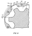
- Fig. 9 provides an enlarged view of a portion of the coupling structure of Fig. 8 .
- the space S 1 between the side of each interior lobe, e.g. 152, and the adjacent side of each spoke of the inner hub 170 may be, for example, .060 inches, while the space S 2 between each side of each lobe, e.g. 133, and each adjacent face of the retainer 190 may be .035 inches, for a coupling where the segments of the inner lobes of the insert lie tangent to a circle 13.652 inches in diameter.
- the angle a between the flat or straight sides of each inner lobe is 60 degrees in the particular illustrative embodiment. Such dimensioning is of course illustrative and will vary with various embodiments as discussed above. Additionally, it may be noted that smaller coupling sizes may not be ideally suited to the use of inserts having the alternate design shown in Figs. 8 and 9 .
- Fig. 10 and 11 illustrate an alternate embodiment wherein an insert 150 is split at three locations so as to form three separate insert section 161, 162, 163.
- the particular illustrated splits shown in this illustrative embodiment are located at the midpoint (radial centerline) of a respective outer lobe, e.g. 152.
- Segmenting an insert 150 as shown in Figs. 10 and 11 lowers the effects of hysteresis, permitting the segmented insert 150 to run cooler and prolonging its life. While Figs. 10 and 11 illustrate an insert divided into three segments, more or less than three segments could be used in various embodiments.
- Fig. 12 illustrates an alternative embodiment where two inserts 15 are arranged to be mounted adjacent one another on extended wings 218 of an inner or second hub 217.
- An axially lengthened retainer, 219 then captures the two inserts 15 and attaches 10 to the face of another hub 13 in the manner generally illustrated in Fig. 1 .
- This design doubles torque handling capability without increasing the diameter of the coupling, which proves useful in applications where space is limited. More than two adjacently mounted inserts may also be provided.
- Couplings as disclosed above have the advantage of combining advantageous aspects of both shear and compression couplings.
- the disclosed couplings normally operate in compression, which prevents exertion of axial thrusts, but can still shear to protect equipment in the event of lock-up or overload, etc.
- An example is the case of shredding apparatus used to shred recycled material. Occasionally, the material will include prohibited foreign objects which can lock the shredder. In such case, the insert of a coupling according to the disclosed design will shear rather than break the associated equipment.
Abstract
Description
- The invention set forth in this specification pertains to new and improved flexible couplings and, more particularly, to such couplings having advantageous features of both shear and compression style couplings.
- Flexible couplings have long been used for the purpose of transmitting rotation from one shaft to another. Such couplings are normally used in order to accommodate comparatively minor shaft alignment problems such as are occasionally encountered because of manufacturing or assembly errors. Because of the fact that these devices are widely used and have been known and used for many years, many different types of flexible couplings have been proposed, built, and used.
- Certain particular flexible couplings have been manufactured in the past so as to include two hubs or hub elements which are adapted to be connected to the shafts joined by the coupling. These hubs are each provided with extending lugs, teeth, or ribs serving as holding means so as to be engaged by corresponding projections on a band-like or beltlike motion transmitting means in order to cause the hubs to rotate in synchronism as one of the shafts is rotated. The bands or belts used in these prior couplings have been flexible, somewhat resilient belts capable of being wrapped around the hubs so that the projections on them engage the holding means on the hubs.
- A metal band or ring is typically used to retain the belt in position wrapped around the hubs. The interior of the band is shaped and dimensioned so that the band may be slid axially relative to the hubs during the assembly and disassembly of the coupling so that the band fits over the belt when the coupling is assembled so as to conform closely to the exterior of the belt.
- Some coupling designs have provided a pair of oppositely-disposed axial grooves in the outer surface of the belt and a pair of oppositely-disposed pins in the inner surface of the metal band. The pins are located so as to slide into the grooves as the metal band is installed along a line parallel to the axis of rotation of the hubs. The pins thus position the band and provide a degree of retention. However, if the shafts are grossly misaligned, the metal band will "walk-off the belt, causing the coupling to come apart. The axial grooves have also been provided with an enlarged central portion such that the pins must be forced through the entrance of the axial groove and then "pop" into place in the central portion to give a tactile indication that the metal band is properly positioned with respect to the flexible belt.
- In our
U.S. Patent Nos. 6,024,644 and5,738,585 , we have disclosed improved "lock-on" apparatus for improving the retention of the aforementioned metal retainer bands. This improved apparatus employs an axial groove for initially receiving a pin located on the underside of the metal retainer band and a circumferential groove opening into the axial groove and into which the retainer band pin may be rotated. In the embodiments illustrated in the referenced applications, the axial groove is bisected by a radial line which also bisects one of the lobes or projections of the flexible belt. The circumferential groove is relatively short, typically having been selected to be two times the width of the retainer ring pin. In practice, such apparatus must contend with vibrations, harmonics, rotation, misalignment and various stresses and forces on the component parts. -
US6183230 discloses an oil pump drive assembly for an internal combustion engine including a crankshaft, a splined hub and a splined isolator ring wherein the inner periphery of the isolator ring is configured for meshing engagement with the male splines of the splined hub and the outer periphery of the isolator ring is configured for meshing engagement with the female splines of the pump rotor. The splined isolator ring operates to minimise noise generation upon impact between the splined hub of the crankshaft and the pump rotor. -
NL7608462 -
EP 0 793 031 A1 representing the closest prior art discloses a device for transmitting rotational power with an elastic member comprising outwardly convex and concave portions. - The invention provides a flexible torque transmitting belt according to claim 1.
- Optional features of the invention are as set out in dependent claims 2 to 7.
- An illustrative and presently preferred embodiment of the invention will now be described in detail in conjunction with the drawings of which:
-
FIG. 1 is an exploded perspective of a coupling according to one embodiment; -
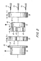
FIG. 2 is a side view of the coupling ofFIG. 1 ; -
FIG. 3 is a perspective end view illustrating a hub, insert and retainer components in assembled relation; -
FIG. 4 is a perspective view of the coupling in the assembled state; -
FIG. 5 is a side cross view of the coupling in the assembled state; -
FIG. 6 is a side cross sectional view of an alternate embodiment; -
FIG. 7 is a side cross section view of an alternate embodiment; -
FIG. 8 is a cross section view of an embodiment according to the invention; -
FIG. 9 is an enlarged view of a portion of the embodiment ofFig. 8 ; -
FIG. 10 is a side view of an alternate embodiment; -
FIG. 11 is a perspective view of the embodiment ofFig. 10 ; and -
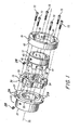
FIG. 12 is a perspective view of an alternate embodiment. - The coupling of the illustrative embodiment includes a
first hub 13, aflexible insert 15, asecond hub 17 and aretainer member 19. Thefirst hub 13 includes aninterior bore 22, a firstcylindrical segment 21 and amounting flange 23 having a circularouter edge 25. Theface 27 of theflange 23 has a number of mountingholes 29 therein, each of which lies equally spaced on a circle of lesser diameter than that of theouter edge 25. Conventional fastening devices such asscrew 28 may be used to secure the hubs to respective shafts. - The
insert 15 is preferably fabricated from a flexible material such as, for example, a suitable urethane, and is preferably split so as to facilitate "wraparound" installation. Theouter surface 31 of theinsert 15 features a number of equally spacedexterior lobes insert 15. The interior surface of theinsert 15 features a number of interiorly projectinglobes FIG. 1 , alternate with theexterior lobes insert 15 one encounters a firstexterior lobe 33, then aninterior lobe 52, then a secondexterior lobe 34, then a secondinterior lobe 53, etc. - The
second hub 17 includes acylindrical segment 43 and an insert-mounting segment orportion 45. The insert-mounting portion 45 includes a number of wells orreceptacles 47 which are shaped and dimensioned to mate snugly with the interior lobes, e.g., 52, 53, of theinsert 15. Thehub 17 is preferably machined as a unitary part from a single piece of metal stock, but of course could be constructed in various other fashions. Thesecond hub 17 further includes aninterior bore 44, typically of circular 25 cross section dimensioned to receive a shaft of cooperating apparatus. - The
interior 49 of theretainer 19 is specially contoured, shaped and dimensioned to receive and snugly mate with the exterior lobes, e.g., 33, 34, of theinsert 15 when the coupling is in the assembled state. The retainer 12 has a first face 61 (FIG. 3 ), which receives and passes theinsert 15 into mating position with theexterior lobes FIG. 1 ) which includes a depending edge orflange portion 65, which prevents theinsert 15 from passing through theretainer 19, i.e., holds theinsert 15 in a position wherein theinsert 15 is preferably encased. by theretainer 19. - In the embodiment illustrated, the width "W1," of the retainer and the width "W2," of the insert are selected such that the
face 71 of theinsert 15 lies flush with the edge of thefirst face 61 of theretainer 19, such that both the insert'sface 71 and theedge 61 lie adjacent theflange face 27 in the assembled state. Thus, in assembly, theretainer 19 "captures" theinsert 15 and is then attached to thefirst hub 13 via a number 10 of fastening devices such as threadedbolts 73. - As shown, for example, in
FIG. 3 , the width W3 of theinsert mating portion 45 of thesecond hub 17 is preferably selected such that its interior face terminates slightly short of the face of theinsert 15. Thus, thesecond hub 17 does not protrude through theinsert 15 or extend to a point where it might contact theflange face 27 of thefirst hub 13.
In operation in the assembled state (FIG. 4 ), the insert is snugly encased and transmits torque and absorbs minor misalignment without exerting axial thrusts on the cooperating shafts to which the first andsecond hubs insert 17 does not tend to exert forces on thehubs central axis 75 of rotation in typical applications. Such forces may cause a hub to move, for example, 15 thousandths of an inch, which is undesirable or unacceptable in certain applications. -
FIGS. 5-7 illustrate various design considerations according to an alternate embodiment. According to this illustrated embodiment, theinsert 15 exhibits a constant shear section width d1. Each exterior lobe, e.g., 33, has respectiveflat sides 81 having a selected length d2 and a central portion 83 between the twoflat sides 81. The central portion 83 has a circular outer contour of radius R1. Adjacent surfaces of the drive ring (retainer) 19 are dimensioned to conform to the shape of the exterior lobe, e.g., 33, for example, in incorporating flat sections, e.g. 85 adjacent theflat sides 81 of the outer lobes, the flat sections e.g., 85 having a length d21. The width d3 of each exterior lobe is the same. - Similar to the exterior lobes, each interior lobe, e.g., 52, has respective
flat sides 87 of equal width d4 and a centralcircular portion 89 connecting thosesides 87 and 5 having a radius R4. The corner to corner width d6 of each interior lobe, e.g., 52, is the same. Finally, the insert includes asplit 101 in one of the outside lobes 33-38 to provide for wraparound installation. - An illustrative dimensioning in inches for a coupling of the size under consideration is as follows:
- R1 = 1.875
- R2 = 1.625
- d1 = .500
- d2 = .730
- d21 =.725
- d3 = 3.978
- d4 = .423
- d5 = .5 10 (flat section of hub wings)
- d6 = 3.325
- R3 = .100
- R4 = .100
- R4 and R3 are respectively inside corner lobe radii and outside corner hub wing radii implemented to resist tearing and cutting. As those skilled in the art will appreciate, the dimensioning of the various widths and radii illustrated in
FIGS. 5-9 , of course, varies, for example, with application and size of a particular coupling. Accordingly, as those skilled in the art will further appreciate, for example, the corner to corner width of the interior lobes and/or the exterior lobes need not all be the same dimension and the exterior lobe and interior lobe widths could be equal in various embodiments. -
FIG. 6 illustrates various clearances of interest with respect to a coupling according to embodiment ofFIGS. 5-7 . The clearance C1 is the clearance between theflat sides 87 of the interior lobes, e.g., 52, and the adjacent surfaces of thecentral hub 17. The clearances C2 are the clearances between theflat side portions 81 of the exterior lobes, e.g., 33, and the adjacent flat portions of theretainer 19. The clearances C5 and C60 are the clearances between the outer and inner diameter of the exterior lobes, e.g., 33, and theretainer 19 andhub 17, respectively. The clearances C3 and C4 are the clearances between the outer and inner diameter of the interior lobes, e.g., 52, and theretainer 17 andhub 17, respectively. Illustrative values in inches for these clearances for a coupling, in which the outside diameter of thering 17 is about 14.72 inches, are: - C1 = .030
- C2 = .035
- C3 = .060
- C4 = .060
- C5 = .060
- C60 = .060
-
FIG. 7 illustrates additional dimensions of interest in an embodiment according toFIG. 5 . In particular, dimension C8 represents the thickness of thatpart 65 of theretainer 19 which overlaps theinsert 15. Dimension C7 represents the clearance range between the opposing faces of the driving and drivenhubs hub 17 is set back from the face of theinsert 15. Dimension C9 represents the clearance between the side face of theinsert 15 and the interior edge of theretainer ring 19. Dimension C10 represents the clearance range between the face of theinsert 15 and the drivenhub 13. Representative dimensions in inches for an illustrative coupling of the size under discussion are: - C6 = .0200
- C7 = .090 - .310
- C8 = .5000
- C9 = .0200
- C10 = .0200 - .2700
- Several observations may be made with respect to operation of the couplings according to various embodiments disclosed herein. First, the flat side surfaces on the interior and exterior lobes facilitate torque transmission. The coupling further provides free axial float, illustrated, for example, by clearance ranges C7 and C10 in
FIG. 7 , as well as relatively wider width W2 of the insert and relatively wider wings W3 of the hub, for example, when compared to features of previous couplings such as ATR Sales' "A" or " M series. In particular applications, the design enables the driving and driven shafts to be positioned at greater distances from one another than previous designs. In such case, for example, greater thermal growth of shafts can be accommodated than in previous systems. -
Fig. 8 illustrates aninsert 150 according to the invention captured by anouter retainer member 190 and receiving asecond hub 170. Theinsert 150 featuresexterior lobes interior lobes Fig. 1 ) but which are contoured differently. In particular, eachlobe circumferentially lying segment 205. Thecentral segment 205 may be either a straight or slightly curved. This construction provides a locking effect which positively locates the rotating parts under load to limit twist and to increase torsional stiffness and stability. It is desirable to provide as much flat side area, e.g. 201, as possible because these areas provide the driving surfaces of the coupling, while theradiused corners -
Fig. 9 provides an enlarged view of a portion of the coupling structure ofFig. 8 . For the particular coupling illustrated, the space S1 between the side of each interior lobe, e.g. 152, and the adjacent side of each spoke of theinner hub 170 may be, for example, .060 inches, while the space S2 between each side of each lobe, e.g. 133, and each adjacent face of theretainer 190 may be .035 inches, for a coupling where the segments of the inner lobes of the insert lie tangent to a circle 13.652 inches in diameter. The angle a between the flat or straight sides of each inner lobe is 60 degrees in the particular illustrative embodiment. Such dimensioning is of course illustrative and will vary with various embodiments as discussed above. Additionally, it may be noted that smaller coupling sizes may not be ideally suited to the use of inserts having the alternate design shown inFigs. 8 and9 . -
Fig. 10 and 11 illustrate an alternate embodiment wherein aninsert 150 is split at three locations so as to form threeseparate insert section insert 150 as shown inFigs. 10 and 11 lowers the effects of hysteresis, permitting thesegmented insert 150 to run cooler and prolonging its life. WhileFigs. 10 and 11 illustrate an insert divided into three segments, more or less than three segments could be used in various embodiments. -
Fig. 12 illustrates an alternative embodiment where twoinserts 15 are arranged to be mounted adjacent one another onextended wings 218 of an inner orsecond hub 217. An axially lengthened retainer, 219 then captures the twoinserts 15 and attaches 10 to the face of anotherhub 13 in the manner generally illustrated inFig. 1 . This design doubles torque handling capability without increasing the diameter of the coupling, which proves useful in applications where space is limited. More than two adjacently mounted inserts may also be provided. - Couplings as disclosed above have the advantage of combining advantageous aspects of both shear and compression couplings. In particular, the disclosed couplings normally operate in compression, which prevents exertion of axial thrusts, but can still shear to protect equipment in the event of lock-up or overload, etc. An example is the case of shredding apparatus used to shred recycled material. Occasionally, the material will include prohibited foreign objects which can lock the shredder. In such case, the insert of a coupling according to the disclosed design will shear rather than break the associated equipment.
- While the present invention has been described above in terms of specific embodiments, it is to be understood that the invention is not limited to the disclosed embodiments. The role of "driving" and "driver hubs" may be reversed and dimensioning adapted to particular sizes and conditions.
Claims (7)
- A flexible torque transmitting belt comprising:a flexible plastic body (150) having an inner and outer surface (31);said outer surface including a plurality of exterior lobes (133,134, 135), each of a selected first width, each including first and second flat sides (201, 202), the distance between respective first ends of said first and second flat sides defining said first width, each exterior lobe having a perimeter comprising a second end of the first flat side leading into a first radiused segment (203), a second end of the second flat side leading into a second radiused segment (204), the first and second radiused segments having the same radius and being connected by a central circumferentially disposed segment (205), the first and second flat sides (201, 202) lying on respective lines which intersect at an acute angle at a point outside said outer surface (31);each exterior lobe comprising a solid body of plastic material in the space defined by said perimeter and a line between said respective first ends of said first and second flat sides;said inner surface including a plurality of interior lobes (152,153,154), each of a selected second width, each including third and fourth flat sides, the distance between respective first ends of said third and fourth flat sides defining said second width, the second end of the third flat side leading into a third radiused segment, a second end of the fourth flat side leading into a fourth radiused segment, the third and fourth radiused segments having the same radius and being interconnected by a central circumferentially disposed segment;each interior lobe comprising a solid body of plastic material in the space encompassed by said perimeter and a line between said respective first ends of said third and fourth flat sides;the first, second, third and fourth flat sides (201, 202) comprising driving surfaces, the first, second, third and fourth radiused segment (203, 204) being shaped and dimensioned to provide a locking function in relation to a cooperating well of a cooperating coupling component.
- The flexible belt of claim 1 wherein each of the interior (152,153,154) and exterior (133,134, 135) lobes are disposed around the circumference of a circle.
- The flexible torque transmitting belt of claim 1 wherein said flexible plastic body (150) comprises a free standing flexible solid circular insert component, which, as a free standing component has each of said exterior lobes and each said interior lobe disposed thereon about the circumference of a circle, and wherein each interior lobe (152,153,154), projects generally concavely into the interior of said body.
- The flexible torque transmitting belt of Claim 1 or claim 3 wherein each central circumferentially disposed segment ( 205) of each exterior lobe (133,134, 135), and each central circumferentially disposed segment of each interior lobe (152,153,154) is substantially straight.
- The flexible torque transmitting belt of Claim 1 or claim 4 wherein said exterior and interior lobes are disposed on a circular central annular portion of said flexible body which provides a constant shear section.
- The flexible belt of claim 1 or claim 5 wherein said interior lobes (152,153,154) alternate with said exterior lobes (133,134, 135), such that, as one proceeds about a circumference of said body one encounters a first exterior lobe (135) , then an interior lobe (152), then an exterior lobe, then an interior lobe in repeating fashion.
- The flexible torque transmitting belt of Claim 3 or claim 6 wherein said free standing flexible insert component further has first and second vertical faces disposed a selected axial width apart.
Applications Claiming Priority (2)
| Application Number | Priority Date | Filing Date | Title |
|---|---|---|---|
| US10/917,940 US7244186B2 (en) | 2002-03-26 | 2004-08-13 | Flexible couplings |
| EP05792614A EP1778993A4 (en) | 2004-08-13 | 2005-08-11 | Flexible couplings |
Related Parent Applications (2)
| Application Number | Title | Priority Date | Filing Date |
|---|---|---|---|
| EP05792614A Division EP1778993A4 (en) | 2004-08-13 | 2005-08-11 | Flexible couplings |
| EP05792614.9 Division | 2005-08-11 |
Publications (3)
| Publication Number | Publication Date |
|---|---|
| EP2063140A2 EP2063140A2 (en) | 2009-05-27 |
| EP2063140A3 EP2063140A3 (en) | 2009-07-01 |
| EP2063140B1 true EP2063140B1 (en) | 2010-12-01 |
Family
ID=35908196
Family Applications (2)
| Application Number | Title | Priority Date | Filing Date |
|---|---|---|---|
| EP05792614A Withdrawn EP1778993A4 (en) | 2004-08-13 | 2005-08-11 | Flexible couplings |
| EP09154509A Active EP2063140B1 (en) | 2004-08-13 | 2005-08-11 | Flexible Couplings |
Family Applications Before (1)
| Application Number | Title | Priority Date | Filing Date |
|---|---|---|---|
| EP05792614A Withdrawn EP1778993A4 (en) | 2004-08-13 | 2005-08-11 | Flexible couplings |
Country Status (7)
| Country | Link |
|---|---|
| US (3) | US7244186B2 (en) |
| EP (2) | EP1778993A4 (en) |
| AT (1) | ATE490418T1 (en) |
| CA (1) | CA2575166A1 (en) |
| DE (1) | DE602005025166D1 (en) |
| ES (1) | ES2357470T3 (en) |
| WO (1) | WO2006020910A2 (en) |
Families Citing this family (16)
| Publication number | Priority date | Publication date | Assignee | Title |
|---|---|---|---|---|
| US7244186B2 (en) * | 2002-03-26 | 2007-07-17 | Hauck Anthony L | Flexible couplings |
| JP5254023B2 (en) * | 2005-10-17 | 2013-08-07 | ボーグワーナー インコーポレーテッド | Coupling device for torque transmission |
| US7534171B2 (en) | 2006-05-30 | 2009-05-19 | Borgwarner Inc. | Spline connector |
| DE102009013082B4 (en) | 2009-03-13 | 2022-01-13 | Neumayer Tekfor Engineering Gmbh | Vibration damper for a drive train |
| DE102009057914B4 (en) | 2009-12-11 | 2021-10-14 | Neumayer Tekfor Engineering Gmbh | Vibration damper for a drive train |
| WO2010102611A1 (en) * | 2009-03-13 | 2010-09-16 | Neumayer Tekfor Holding Gmbh | Vibration absorber for a drive train |
| FR2945091B1 (en) * | 2009-04-30 | 2011-05-13 | Somfy Sas | DEVICE FOR VISCOELASTIC TRANSMISSION OF A ACTUATOR OF A SHUTTER |
| DE102012101388A1 (en) * | 2012-02-21 | 2013-08-22 | Thyssenkrupp Presta Aktiengesellschaft | Steering shaft for a motor vehicle |
| FR2991019B1 (en) * | 2012-05-24 | 2015-07-24 | Skf Ab | PULLEY DEVICE FOR AIR CONDITIONING COMPRESSOR |
| US9091316B2 (en) * | 2013-03-13 | 2015-07-28 | Trd U.S.A., Inc. | Dampers for crankshafts of reciprocating engines and reciprocating engines comprising the same |
| US20140295978A1 (en) * | 2013-03-26 | 2014-10-02 | Frederik Jan Louwersheimer | Insert for shear-type flexible shaft couplings |
| DE102014223534A1 (en) * | 2014-11-18 | 2016-05-19 | Zf Friedrichshafen Ag | Elastomeric bearing for a vehicle |
| CN105485191A (en) * | 2015-12-29 | 2016-04-13 | 武汉正通传动技术有限公司 | Double-drum-shaped gear coupling |
| US10449648B2 (en) * | 2016-08-04 | 2019-10-22 | Robert Bosch Tool Corporation | Transferring rotation torque through isolator for table saw |
| US9683609B1 (en) * | 2016-09-13 | 2017-06-20 | Jerry L. Hauck | Flexible couplings with improved torque transmitting insert |
| US10690193B2 (en) * | 2017-04-03 | 2020-06-23 | Atr Sales, Inc. | Flexible couplings with free spin mode prevention |
Family Cites Families (32)
| Publication number | Priority date | Publication date | Assignee | Title |
|---|---|---|---|---|
| US375975A (en) * | 1888-01-03 | Fastener for m eeting-rails of sash es | ||
| DE97473C (en) | ||||
| BE511458A (en) * | ||||
| DE373687C (en) * | 1923-04-14 | Frederick Richard Simms | Shaft coupling | |
| US376975A (en) * | 1888-01-24 | Tob of said pateick adie | ||
| US1017819A (en) * | 1911-09-05 | 1912-02-20 | Otis Elevator Co | Gearing. |
| GB245847A (en) * | 1924-10-15 | 1926-01-15 | British Thomson Houston Co Ltd | Improvements in and relating to shaft couplings |
| US1890080A (en) * | 1928-08-08 | 1932-12-06 | Abraham L Freedlander | Double cog belt |
| US1994604A (en) * | 1932-11-01 | 1935-03-19 | Houghton & Co E F | Embossed belting |
| US2235605A (en) * | 1937-03-10 | 1941-03-18 | Bugatti Ettore | Screw propeller |
| US2232637A (en) * | 1938-01-24 | 1941-02-18 | Falk Corp | Coupling |
| US2562166A (en) * | 1945-05-23 | 1951-07-31 | Wilfrid H Bendall | Gear belt power transmission |
| US2564826A (en) * | 1948-09-27 | 1951-08-21 | Ray A Yoder | Torque and speed responsive clutch |
| US2867102A (en) * | 1956-02-13 | 1959-01-06 | Woods T B Sons Co | Flexible couplings for shafts |
| US2866103A (en) * | 1956-08-22 | 1958-12-23 | Bell Telephone Labor Inc | Diode gate and sampling circuit |
| US2867103A (en) * | 1957-04-01 | 1959-01-06 | Woods T B Sons Co | Gripping arrangements for flexible couplings for power transmission shafts |
| DE2042260A1 (en) | 1970-08-26 | 1972-03-02 | Hauke H | Zahnflex coupling |
| FR2172580A5 (en) * | 1972-02-18 | 1973-09-28 | Glaenzer Spicer Sa | |
| US3988941A (en) * | 1975-08-01 | 1976-11-02 | Smith Thomas R | Drive belt |
| US4033020A (en) * | 1975-08-04 | 1977-07-05 | Trw Inc. | Method of making a slip joint |
| US4662863A (en) * | 1985-08-30 | 1987-05-05 | Uniroyal Power Transmission Co., Inc. | Double-acting power transmission belt |
| US5295911A (en) * | 1992-06-05 | 1994-03-22 | Hoyt Iii Raymond E | Horizontal shear mode flexible coupling |
| CA2137855C (en) * | 1994-10-12 | 1999-03-30 | Raymond E. Hoyt, Iii | Flexible couplings with walk-off detect and lock-on feature |
| US5738585A (en) * | 1994-10-12 | 1998-04-14 | Hoyt, Iii; Raymond Earl | Compact flexible couplings with inside diameter belt support and lock-on features |
| JP3671571B2 (en) * | 1996-02-29 | 2005-07-13 | 株式会社デンソー | Power transmission device |
| CA2203617C (en) * | 1996-04-26 | 2000-08-08 | Hiroshi Jonen | Power transmission belt |
| JP3446538B2 (en) * | 1997-02-26 | 2003-09-16 | 株式会社デンソー | Power transmission device |
| US6183230B1 (en) * | 1999-03-19 | 2001-02-06 | General Motors Corporation | Isolated engine oil pump drive |
| US6342011B1 (en) * | 1999-04-01 | 2002-01-29 | The Falk Corporation | Flexible shaft coupling with improved elastomeric element |
| US7244186B2 (en) * | 2002-03-26 | 2007-07-17 | Hauck Anthony L | Flexible couplings |
| US20030186749A1 (en) * | 2002-03-26 | 2003-10-02 | Atr Sales, Inc. | Flexible couplings |
| FR2853373B1 (en) * | 2003-04-02 | 2006-03-03 | Hutchinson | DECOUPLING ELEMENT OF DEFORMABLE MATERIAL IN A POWER TRANSMISSION SYSTEM |
-
2004
- 2004-08-13 US US10/917,940 patent/US7244186B2/en not_active Expired - Lifetime
-
2005
- 2005-08-11 EP EP05792614A patent/EP1778993A4/en not_active Withdrawn
- 2005-08-11 AT AT09154509T patent/ATE490418T1/en not_active IP Right Cessation
- 2005-08-11 ES ES09154509T patent/ES2357470T3/en active Active
- 2005-08-11 DE DE602005025166T patent/DE602005025166D1/en active Active
- 2005-08-11 CA CA002575166A patent/CA2575166A1/en not_active Abandoned
- 2005-08-11 WO PCT/US2005/028816 patent/WO2006020910A2/en active Application Filing
- 2005-08-11 EP EP09154509A patent/EP2063140B1/en active Active
-
2007
- 2007-07-16 US US11/778,512 patent/US20080015035A1/en not_active Abandoned
-
2009
- 2009-02-04 US US12/365,849 patent/US7806771B2/en not_active Expired - Lifetime
Also Published As
| Publication number | Publication date |
|---|---|
| EP1778993A4 (en) | 2009-01-21 |
| DE602005025166D1 (en) | 2011-01-13 |
| EP2063140A2 (en) | 2009-05-27 |
| WO2006020910A3 (en) | 2006-11-16 |
| US20050192103A1 (en) | 2005-09-01 |
| US20080015035A1 (en) | 2008-01-17 |
| ATE490418T1 (en) | 2010-12-15 |
| ES2357470T3 (en) | 2011-04-26 |
| WO2006020910A2 (en) | 2006-02-23 |
| EP2063140A3 (en) | 2009-07-01 |
| CA2575166A1 (en) | 2006-02-23 |
| US7244186B2 (en) | 2007-07-17 |
| EP1778993A2 (en) | 2007-05-02 |
| US7806771B2 (en) | 2010-10-05 |
| US20090143148A1 (en) | 2009-06-04 |
Similar Documents
| Publication | Publication Date | Title |
|---|---|---|
| EP2063140B1 (en) | Flexible Couplings | |
| US6142878A (en) | Flexible coupling with elastomeric belt | |
| US4813808A (en) | Axial retaining member and method for interconnecting male and female splined members | |
| US4068965A (en) | Shaft coupling | |
| US5692410A (en) | Rotatable apparatus having a stress dissipation structure | |
| CA1062928A (en) | Stroking universal joint housing | |
| US6106421A (en) | Uncoupled belt pulley | |
| JPS639726A (en) | Elastic shaft coupling | |
| US20090263181A1 (en) | Joint assembly with centering flange | |
| US5910049A (en) | Elastomeric coupling system | |
| US20050130749A1 (en) | Flexible couplings | |
| US6648763B2 (en) | Reduction of axial thrust reaction in toothed shear-type flexible couplings | |
| US7270606B2 (en) | Power transmission device | |
| US3798924A (en) | Shaft coupling and element therefor | |
| US2588158A (en) | Rubber cushion drive coupling | |
| EP0299980A1 (en) | Spline anti-backlash device | |
| US20200166113A1 (en) | Sprocket with elastomer cushion ring | |
| EP0102065B1 (en) | Shaft coupling | |
| JP2001041308A (en) | Power transmission device | |
| US9683609B1 (en) | Flexible couplings with improved torque transmitting insert | |
| KR102325003B1 (en) | Shaft joint coupling structure | |
| JP2000179568A (en) | Power transmission | |
| EP1084350B1 (en) | Flat key washer | |
| US10690193B2 (en) | Flexible couplings with free spin mode prevention | |
| GB2075151A (en) | Flexible couplings |
Legal Events
| Date | Code | Title | Description |
|---|---|---|---|
| PUAI | Public reference made under article 153(3) epc to a published international application that has entered the european phase |
Free format text: ORIGINAL CODE: 0009012 |
|
| AC | Divisional application: reference to earlier application |
Ref document number: 1778993 Country of ref document: EP Kind code of ref document: P |
|
| AK | Designated contracting states |
Kind code of ref document: A2 Designated state(s): AT BE BG CH CY CZ DE DK EE ES FI FR GB GR HU IE IS IT LI LT LU LV MC NL PL PT RO SE SI SK TR |
|
| PUAL | Search report despatched |
Free format text: ORIGINAL CODE: 0009013 |
|
| AK | Designated contracting states |
Kind code of ref document: A3 Designated state(s): AT BE BG CH CY CZ DE DK EE ES FI FR GB GR HU IE IS IT LI LT LU LV MC NL PL PT RO SE SI SK TR |
|
| 17P | Request for examination filed |
Effective date: 20091106 |
|
| AKX | Designation fees paid |
Designated state(s): AT BE BG CH CY CZ DE DK EE ES FI FR GB GR HU IE IS IT LI LT LU LV MC NL PL PT RO SE SI SK TR |
|
| GRAP | Despatch of communication of intention to grant a patent |
Free format text: ORIGINAL CODE: EPIDOSNIGR1 |
|
| GRAS | Grant fee paid |
Free format text: ORIGINAL CODE: EPIDOSNIGR3 |
|
| GRAA | (expected) grant |
Free format text: ORIGINAL CODE: 0009210 |
|
| AC | Divisional application: reference to earlier application |
Ref document number: 1778993 Country of ref document: EP Kind code of ref document: P |
|
| AK | Designated contracting states |
Kind code of ref document: B1 Designated state(s): AT BE BG CH CY CZ DE DK EE ES FI FR GB GR HU IE IS IT LI LT LU LV MC NL PL PT RO SE SI SK TR |
|
| REG | Reference to a national code |
Ref country code: GB Ref legal event code: FG4D |
|
| REG | Reference to a national code |
Ref country code: CH Ref legal event code: EP |
|
| REG | Reference to a national code |
Ref country code: IE Ref legal event code: FG4D |
|
| REF | Corresponds to: |
Ref document number: 602005025166 Country of ref document: DE Date of ref document: 20110113 Kind code of ref document: P |
|
| REG | Reference to a national code |
Ref country code: SE Ref legal event code: TRGR |
|
| REG | Reference to a national code |
Ref country code: NL Ref legal event code: VDEP Effective date: 20101201 |
|
| REG | Reference to a national code |
Ref country code: ES Ref legal event code: FG2A Ref document number: 2357470 Country of ref document: ES Kind code of ref document: T3 Effective date: 20110426 |
|
| PG25 | Lapsed in a contracting state [announced via postgrant information from national office to epo] |
Ref country code: LT Free format text: LAPSE BECAUSE OF FAILURE TO SUBMIT A TRANSLATION OF THE DESCRIPTION OR TO PAY THE FEE WITHIN THE PRESCRIBED TIME-LIMIT Effective date: 20101201 |
|
| LTIE | Lt: invalidation of european patent or patent extension |
Effective date: 20101201 |
|
| PG25 | Lapsed in a contracting state [announced via postgrant information from national office to epo] |
Ref country code: CY Free format text: LAPSE BECAUSE OF FAILURE TO SUBMIT A TRANSLATION OF THE DESCRIPTION OR TO PAY THE FEE WITHIN THE PRESCRIBED TIME-LIMIT Effective date: 20101201 Ref country code: SI Free format text: LAPSE BECAUSE OF FAILURE TO SUBMIT A TRANSLATION OF THE DESCRIPTION OR TO PAY THE FEE WITHIN THE PRESCRIBED TIME-LIMIT Effective date: 20101201 Ref country code: LV Free format text: LAPSE BECAUSE OF FAILURE TO SUBMIT A TRANSLATION OF THE DESCRIPTION OR TO PAY THE FEE WITHIN THE PRESCRIBED TIME-LIMIT Effective date: 20101201 Ref country code: FI Free format text: LAPSE BECAUSE OF FAILURE TO SUBMIT A TRANSLATION OF THE DESCRIPTION OR TO PAY THE FEE WITHIN THE PRESCRIBED TIME-LIMIT Effective date: 20101201 Ref country code: AT Free format text: LAPSE BECAUSE OF FAILURE TO SUBMIT A TRANSLATION OF THE DESCRIPTION OR TO PAY THE FEE WITHIN THE PRESCRIBED TIME-LIMIT Effective date: 20101201 Ref country code: BG Free format text: LAPSE BECAUSE OF FAILURE TO SUBMIT A TRANSLATION OF THE DESCRIPTION OR TO PAY THE FEE WITHIN THE PRESCRIBED TIME-LIMIT Effective date: 20110301 Ref country code: NL Free format text: LAPSE BECAUSE OF FAILURE TO SUBMIT A TRANSLATION OF THE DESCRIPTION OR TO PAY THE FEE WITHIN THE PRESCRIBED TIME-LIMIT Effective date: 20101201 |
|
| PG25 | Lapsed in a contracting state [announced via postgrant information from national office to epo] |
Ref country code: GR Free format text: LAPSE BECAUSE OF FAILURE TO SUBMIT A TRANSLATION OF THE DESCRIPTION OR TO PAY THE FEE WITHIN THE PRESCRIBED TIME-LIMIT Effective date: 20110302 |
|
| PG25 | Lapsed in a contracting state [announced via postgrant information from national office to epo] |
Ref country code: EE Free format text: LAPSE BECAUSE OF FAILURE TO SUBMIT A TRANSLATION OF THE DESCRIPTION OR TO PAY THE FEE WITHIN THE PRESCRIBED TIME-LIMIT Effective date: 20101201 Ref country code: IS Free format text: LAPSE BECAUSE OF FAILURE TO SUBMIT A TRANSLATION OF THE DESCRIPTION OR TO PAY THE FEE WITHIN THE PRESCRIBED TIME-LIMIT Effective date: 20110401 Ref country code: CZ Free format text: LAPSE BECAUSE OF FAILURE TO SUBMIT A TRANSLATION OF THE DESCRIPTION OR TO PAY THE FEE WITHIN THE PRESCRIBED TIME-LIMIT Effective date: 20101201 Ref country code: BE Free format text: LAPSE BECAUSE OF FAILURE TO SUBMIT A TRANSLATION OF THE DESCRIPTION OR TO PAY THE FEE WITHIN THE PRESCRIBED TIME-LIMIT Effective date: 20101201 Ref country code: PT Free format text: LAPSE BECAUSE OF FAILURE TO SUBMIT A TRANSLATION OF THE DESCRIPTION OR TO PAY THE FEE WITHIN THE PRESCRIBED TIME-LIMIT Effective date: 20110401 |
|
| PG25 | Lapsed in a contracting state [announced via postgrant information from national office to epo] |
Ref country code: PL Free format text: LAPSE BECAUSE OF FAILURE TO SUBMIT A TRANSLATION OF THE DESCRIPTION OR TO PAY THE FEE WITHIN THE PRESCRIBED TIME-LIMIT Effective date: 20101201 Ref country code: SK Free format text: LAPSE BECAUSE OF FAILURE TO SUBMIT A TRANSLATION OF THE DESCRIPTION OR TO PAY THE FEE WITHIN THE PRESCRIBED TIME-LIMIT Effective date: 20101201 Ref country code: RO Free format text: LAPSE BECAUSE OF FAILURE TO SUBMIT A TRANSLATION OF THE DESCRIPTION OR TO PAY THE FEE WITHIN THE PRESCRIBED TIME-LIMIT Effective date: 20101201 |
|
| PGFP | Annual fee paid to national office [announced via postgrant information from national office to epo] |
Ref country code: LU Payment date: 20110825 Year of fee payment: 7 |
|
| PLBE | No opposition filed within time limit |
Free format text: ORIGINAL CODE: 0009261 |
|
| STAA | Information on the status of an ep patent application or granted ep patent |
Free format text: STATUS: NO OPPOSITION FILED WITHIN TIME LIMIT |
|
| PG25 | Lapsed in a contracting state [announced via postgrant information from national office to epo] |
Ref country code: DK Free format text: LAPSE BECAUSE OF FAILURE TO SUBMIT A TRANSLATION OF THE DESCRIPTION OR TO PAY THE FEE WITHIN THE PRESCRIBED TIME-LIMIT Effective date: 20101201 |
|
| PGFP | Annual fee paid to national office [announced via postgrant information from national office to epo] |
Ref country code: MC Payment date: 20110726 Year of fee payment: 7 Ref country code: IE Payment date: 20110810 Year of fee payment: 7 Ref country code: CH Payment date: 20110812 Year of fee payment: 7 |
|
| 26N | No opposition filed |
Effective date: 20110902 |
|
| REG | Reference to a national code |
Ref country code: DE Ref legal event code: R097 Ref document number: 602005025166 Country of ref document: DE Effective date: 20110902 |
|
| PG25 | Lapsed in a contracting state [announced via postgrant information from national office to epo] |
Ref country code: IT Free format text: LAPSE BECAUSE OF FAILURE TO SUBMIT A TRANSLATION OF THE DESCRIPTION OR TO PAY THE FEE WITHIN THE PRESCRIBED TIME-LIMIT Effective date: 20101201 |
|
| PGFP | Annual fee paid to national office [announced via postgrant information from national office to epo] |
Ref country code: NL Payment date: 20110818 Year of fee payment: 7 |
|
| PGFP | Annual fee paid to national office [announced via postgrant information from national office to epo] |
Ref country code: ES Payment date: 20120928 Year of fee payment: 8 |
|
| REG | Reference to a national code |
Ref country code: CH Ref legal event code: PL |
|
| PG25 | Lapsed in a contracting state [announced via postgrant information from national office to epo] |
Ref country code: MC Free format text: LAPSE BECAUSE OF NON-PAYMENT OF DUE FEES Effective date: 20120831 |
|
| PG25 | Lapsed in a contracting state [announced via postgrant information from national office to epo] |
Ref country code: CH Free format text: LAPSE BECAUSE OF NON-PAYMENT OF DUE FEES Effective date: 20120831 Ref country code: LI Free format text: LAPSE BECAUSE OF NON-PAYMENT OF DUE FEES Effective date: 20120831 |
|
| REG | Reference to a national code |
Ref country code: IE Ref legal event code: MM4A |
|
| PG25 | Lapsed in a contracting state [announced via postgrant information from national office to epo] |
Ref country code: IE Free format text: LAPSE BECAUSE OF NON-PAYMENT OF DUE FEES Effective date: 20120811 |
|
| PG25 | Lapsed in a contracting state [announced via postgrant information from national office to epo] |
Ref country code: TR Free format text: LAPSE BECAUSE OF FAILURE TO SUBMIT A TRANSLATION OF THE DESCRIPTION OR TO PAY THE FEE WITHIN THE PRESCRIBED TIME-LIMIT Effective date: 20101201 |
|
| PG25 | Lapsed in a contracting state [announced via postgrant information from national office to epo] |
Ref country code: HU Free format text: LAPSE BECAUSE OF FAILURE TO SUBMIT A TRANSLATION OF THE DESCRIPTION OR TO PAY THE FEE WITHIN THE PRESCRIBED TIME-LIMIT Effective date: 20101201 |
|
| PG25 | Lapsed in a contracting state [announced via postgrant information from national office to epo] |
Ref country code: LU Free format text: LAPSE BECAUSE OF NON-PAYMENT OF DUE FEES Effective date: 20120811 |
|
| PG25 | Lapsed in a contracting state [announced via postgrant information from national office to epo] |
Ref country code: ES Free format text: LAPSE BECAUSE OF NON-PAYMENT OF DUE FEES Effective date: 20130812 |
|
| REG | Reference to a national code |
Ref country code: FR Ref legal event code: PLFP Year of fee payment: 11 |
|
| REG | Reference to a national code |
Ref country code: FR Ref legal event code: PLFP Year of fee payment: 12 |
|
| REG | Reference to a national code |
Ref country code: FR Ref legal event code: PLFP Year of fee payment: 13 |
|
| REG | Reference to a national code |
Ref country code: FR Ref legal event code: PLFP Year of fee payment: 14 |
|
| PGFP | Annual fee paid to national office [announced via postgrant information from national office to epo] |
Ref country code: GB Payment date: 20230817 Year of fee payment: 19 |
|
| PGFP | Annual fee paid to national office [announced via postgrant information from national office to epo] |
Ref country code: SE Payment date: 20230830 Year of fee payment: 19 Ref country code: FR Payment date: 20230821 Year of fee payment: 19 Ref country code: DE Payment date: 20230822 Year of fee payment: 19 |