EP2063083A1 - Control device for multi-stage turbochargers - Google Patents
Control device for multi-stage turbochargers Download PDFInfo
- Publication number
- EP2063083A1 EP2063083A1 EP07806926A EP07806926A EP2063083A1 EP 2063083 A1 EP2063083 A1 EP 2063083A1 EP 07806926 A EP07806926 A EP 07806926A EP 07806926 A EP07806926 A EP 07806926A EP 2063083 A1 EP2063083 A1 EP 2063083A1
- Authority
- EP
- European Patent Office
- Prior art keywords
- opening degree
- state
- stage
- engine
- pressure
- Prior art date
- Legal status (The legal status is an assumption and is not a legal conclusion. Google has not performed a legal analysis and makes no representation as to the accuracy of the status listed.)
- Granted
Links
Images


Classifications
-
- F—MECHANICAL ENGINEERING; LIGHTING; HEATING; WEAPONS; BLASTING
- F02—COMBUSTION ENGINES; HOT-GAS OR COMBUSTION-PRODUCT ENGINE PLANTS
- F02B—INTERNAL-COMBUSTION PISTON ENGINES; COMBUSTION ENGINES IN GENERAL
- F02B37/00—Engines characterised by provision of pumps driven at least for part of the time by exhaust
- F02B37/013—Engines characterised by provision of pumps driven at least for part of the time by exhaust with exhaust-driven pumps arranged in series
-
- F—MECHANICAL ENGINEERING; LIGHTING; HEATING; WEAPONS; BLASTING
- F02—COMBUSTION ENGINES; HOT-GAS OR COMBUSTION-PRODUCT ENGINE PLANTS
- F02B—INTERNAL-COMBUSTION PISTON ENGINES; COMBUSTION ENGINES IN GENERAL
- F02B37/00—Engines characterised by provision of pumps driven at least for part of the time by exhaust
- F02B37/004—Engines characterised by provision of pumps driven at least for part of the time by exhaust with exhaust drives arranged in series
-
- F—MECHANICAL ENGINEERING; LIGHTING; HEATING; WEAPONS; BLASTING
- F02—COMBUSTION ENGINES; HOT-GAS OR COMBUSTION-PRODUCT ENGINE PLANTS
- F02B—INTERNAL-COMBUSTION PISTON ENGINES; COMBUSTION ENGINES IN GENERAL
- F02B37/00—Engines characterised by provision of pumps driven at least for part of the time by exhaust
- F02B37/12—Control of the pumps
- F02B37/24—Control of the pumps by using pumps or turbines with adjustable guide vanes
-
- F—MECHANICAL ENGINEERING; LIGHTING; HEATING; WEAPONS; BLASTING
- F02—COMBUSTION ENGINES; HOT-GAS OR COMBUSTION-PRODUCT ENGINE PLANTS
- F02D—CONTROLLING COMBUSTION ENGINES
- F02D41/00—Electrical control of supply of combustible mixture or its constituents
- F02D41/0002—Controlling intake air
- F02D41/0007—Controlling intake air for control of turbo-charged or super-charged engines
-
- F—MECHANICAL ENGINEERING; LIGHTING; HEATING; WEAPONS; BLASTING
- F02—COMBUSTION ENGINES; HOT-GAS OR COMBUSTION-PRODUCT ENGINE PLANTS
- F02M—SUPPLYING COMBUSTION ENGINES IN GENERAL WITH COMBUSTIBLE MIXTURES OR CONSTITUENTS THEREOF
- F02M26/00—Engine-pertinent apparatus for adding exhaust gases to combustion-air, main fuel or fuel-air mixture, e.g. by exhaust gas recirculation [EGR] systems
- F02M26/02—EGR systems specially adapted for supercharged engines
- F02M26/08—EGR systems specially adapted for supercharged engines for engines having two or more intake charge compressors or exhaust gas turbines, e.g. a turbocharger combined with an additional compressor
-
- F—MECHANICAL ENGINEERING; LIGHTING; HEATING; WEAPONS; BLASTING
- F02—COMBUSTION ENGINES; HOT-GAS OR COMBUSTION-PRODUCT ENGINE PLANTS
- F02B—INTERNAL-COMBUSTION PISTON ENGINES; COMBUSTION ENGINES IN GENERAL
- F02B29/00—Engines characterised by provision for charging or scavenging not provided for in groups F02B25/00, F02B27/00 or F02B33/00 - F02B39/00; Details thereof
- F02B29/04—Cooling of air intake supply
- F02B29/0406—Layout of the intake air cooling or coolant circuit
-
- F—MECHANICAL ENGINEERING; LIGHTING; HEATING; WEAPONS; BLASTING
- F02—COMBUSTION ENGINES; HOT-GAS OR COMBUSTION-PRODUCT ENGINE PLANTS
- F02D—CONTROLLING COMBUSTION ENGINES
- F02D2200/00—Input parameters for engine control
- F02D2200/02—Input parameters for engine control the parameters being related to the engine
- F02D2200/04—Engine intake system parameters
- F02D2200/0406—Intake manifold pressure
-
- F—MECHANICAL ENGINEERING; LIGHTING; HEATING; WEAPONS; BLASTING
- F02—COMBUSTION ENGINES; HOT-GAS OR COMBUSTION-PRODUCT ENGINE PLANTS
- F02D—CONTROLLING COMBUSTION ENGINES
- F02D41/00—Electrical control of supply of combustible mixture or its constituents
- F02D41/02—Circuit arrangements for generating control signals
- F02D41/18—Circuit arrangements for generating control signals by measuring intake air flow
- F02D41/187—Circuit arrangements for generating control signals by measuring intake air flow using a hot wire flow sensor
-
- F—MECHANICAL ENGINEERING; LIGHTING; HEATING; WEAPONS; BLASTING
- F02—COMBUSTION ENGINES; HOT-GAS OR COMBUSTION-PRODUCT ENGINE PLANTS
- F02M—SUPPLYING COMBUSTION ENGINES IN GENERAL WITH COMBUSTIBLE MIXTURES OR CONSTITUENTS THEREOF
- F02M26/00—Engine-pertinent apparatus for adding exhaust gases to combustion-air, main fuel or fuel-air mixture, e.g. by exhaust gas recirculation [EGR] systems
- F02M26/02—EGR systems specially adapted for supercharged engines
- F02M26/09—Constructional details, e.g. structural combinations of EGR systems and supercharger systems; Arrangement of the EGR and supercharger systems with respect to the engine
- F02M26/10—Constructional details, e.g. structural combinations of EGR systems and supercharger systems; Arrangement of the EGR and supercharger systems with respect to the engine having means to increase the pressure difference between the exhaust and intake system, e.g. venturis, variable geometry turbines, check valves using pressure pulsations or throttles in the air intake or exhaust system
-
- F—MECHANICAL ENGINEERING; LIGHTING; HEATING; WEAPONS; BLASTING
- F02—COMBUSTION ENGINES; HOT-GAS OR COMBUSTION-PRODUCT ENGINE PLANTS
- F02M—SUPPLYING COMBUSTION ENGINES IN GENERAL WITH COMBUSTIBLE MIXTURES OR CONSTITUENTS THEREOF
- F02M26/00—Engine-pertinent apparatus for adding exhaust gases to combustion-air, main fuel or fuel-air mixture, e.g. by exhaust gas recirculation [EGR] systems
- F02M26/13—Arrangement or layout of EGR passages, e.g. in relation to specific engine parts or for incorporation of accessories
- F02M26/22—Arrangement or layout of EGR passages, e.g. in relation to specific engine parts or for incorporation of accessories with coolers in the recirculation passage
- F02M26/23—Layout, e.g. schematics
-
- Y—GENERAL TAGGING OF NEW TECHNOLOGICAL DEVELOPMENTS; GENERAL TAGGING OF CROSS-SECTIONAL TECHNOLOGIES SPANNING OVER SEVERAL SECTIONS OF THE IPC; TECHNICAL SUBJECTS COVERED BY FORMER USPC CROSS-REFERENCE ART COLLECTIONS [XRACs] AND DIGESTS
- Y02—TECHNOLOGIES OR APPLICATIONS FOR MITIGATION OR ADAPTATION AGAINST CLIMATE CHANGE
- Y02T—CLIMATE CHANGE MITIGATION TECHNOLOGIES RELATED TO TRANSPORTATION
- Y02T10/00—Road transport of goods or passengers
- Y02T10/10—Internal combustion engine [ICE] based vehicles
- Y02T10/12—Improving ICE efficiencies
Definitions
- the present invention relates to a control device for multi-stage turbochargers in which turbochargers of at least two stages are provided in series.
- NOx nitrogen oxide
- PM diesel particulate
- FIG. 3 illustrates a transient (JE05 mode) operation mode adapted in Japan and test data.
- Time (sec) is plotted against the abscissa, and smoke - lambda - engine revolution speed are plotted in the order of description from below on the ordinate.
- a two-stage turbo system can be considered as a system capable of supplying high supercharge to an engine with the object of satisfying the above-described exhaust gas standards.
- a two-stage turbo system is basically a system in which by disposing two turbochargers for an engine, it is possible to realize a supercharge that is higher than that in the conventional single turbo engine over the entire engine operation range.
- the problem associated with the two-stage turbo system is that a pressure increase lag occurs in a turbocharger disposed in a low-pressure stage (rear stage) in a rise period e.g. in a transient test mode.
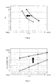
- FIG. 4 shows comparison results on a turbo pressure (boost pressure) rise of a single-turbo system and a two-stage turbo system in a transient period.
- a variable vane (VGT) of the turbo disposed in the first stage (high-pressure stage) can be controlled with a map (see Table 2) in which an opening degree is further reduced with respect to that of the map (see Table 1) obtained in the stationary test.
- the pressure increase of the entire two-stage turbo system can be accelerated with respect to that of a single turbo.
- the target exhaust level can thus be reached by changing the opening degree of a variable vane (VGT) of a high-pressure stage turbocharger disposed in the first stage to that of the map of Table 2 in which the opening degree of a variable vane (VGT opening degree) is reduced with respect to that of the VGT base map shown in Table 1 and improving the rise of boost pressure.
- VVT variable vane
- the problem is that where the opening degree of the variable vane is reduced, fuel consumption is worsened, as shown in FIG. 7 .
- FIG. 7 shows fuel consumption results of a total test simulating the aforementioned JE05 mode.
- the total test includes not only a test in a transient state, but also a test in a state with gradual changes, that is, in a stationary state.
- the opening degree in the turbo map is reduced more than necessary in the stationary state and the intake air is unnecessarily supplied and pressurized, thereby worsening fuel consumption. Further, even in the transient state, the opening degree in the turbo map is reduced more than necessary, thereby causing worsening of fuel consumption.
- the present invention provides a control device for multi-stage turbochargers which are turbochargers of at least two or more stages provided in series at an engine and in which a high-pressure stage turbocharger is configured by a variable-capacity turbocharger equipped with a variable vane, comprising: detection means for detecting a boost pressure or an intake air amount of a turbocharger of a stage with a pressure lower than that of the variable-capacity turbocharger, wherein an opening degree of the variable vane is controlled on the basis of a detection value of the detection means.
- control device comprise storage means for storing a stationary-state opening degree map in which the opening degree of the variable vane in a stationary state of the engine is recorded and a transient-state opening degree map in which the opening degree is set lower than that in the stationary-state opening degree map, wherein in the stationary state of the engine, the opening degree of the variable vane is controlled based on the stationary-state opening degree map, and in the transient state of the engine, when the detection value of the detection means exceeds a predetermined value, the opening degree of the variable vane is controlled based on the stationary-state opening degree map, and when the detection value is equal to or lower than the predetermined value, the opening degree of the variable vane is controlled based on the transient-state opening degree map.
- the present invention provides a control device for multi-stage turbochargers which are turbochargers of at least two or more stages provided in series at an engine and in which a high-pressure stage turbocharger is configured by a variable-capacity turbocharger equipped with a variable vane and an opening degree of the variable vane is reduced with respect to an opening degree in a stationary state when the engine revolution speed is increased, comprising: detection means for detecting a boost pressure or an intake air amount of a turbocharger of a stage with a pressure lower than that of the variable-capacity turbocharger; and prohibition means for prohibiting a reduction of the opening degree of the variable vane when a detection value of the detection means exceeds a predetermined value even when the engine revolution speed is increased.
- the present invention demonstrates an excellent effect of enabling the improvement of fuel consumption in transient and stationary states of an engine equipped with multi-stage turbochargers.
- a control device for multi-stage turbochargers of the present embodiment is designed, for example, for a two-stage turbo system mounted on a diesel engine (referred to hereinbelow as "engine") of a vehicle.
- FIG. 1 A schematic structure of the engine will be described based on FIG. 1 .
- an engine 2 includes an engine body 3 having a plurality of cylinders, an intake passage 4 and an exhaust passage 5 connected to the engine body 3, turbochargers 6, 7 provided in these intake passage 4 and exhaust passage 5 and serving to supply supercharged air to the engine body 3, an EGR device 8 for returning part of exhaust gas of the exhaust passage 5 to the intake passage 4, and an engine control unit (referred to hereinbelow as ECU) 1 for controlling the engine body 3.
- ECU engine control unit
- the high-pressure stage turbocharger (HP) 6 and the low-pressure stage turbocharger (LP) 7 are provided in series and configure a two-stage system.
- a maf sensor 11 a compressor (LPC, referred to hereinbelow as low-pressure stage compressor) 71 of the low-pressure stage turbocharger 7, a boost sensor 12, a compressor (HPC, referred to hereinbelow as high-pressure stage compressor) 61 of the high-pressure stage turbocharger 6, and an air cooler (A/C) 31 are provided in the order of description from the upstream side in the intake passage 4.
- a downstream end of the intake passage 4 is connected to an air intake manifold (not shown in the figure) of the engine body 3.
- An upstream end of the exhaust passage 5 is connected to an exhaust manifold (not shown in the figure) of the engine body 3.
- a turbine (HPT, referred to hereinbelow as high-pressure stage turbine) 62 of the high-pressure stage turbocharger 6 and a turbine (LPT, referred to hereinbelow as low-pressure stage turbine) 72 of the low-pressure stage turbocharger 7 are provided in the order of description from the upstream side in the exhaust passage 5.
- the low-pressure stage turbocharger 7 includes the above-described low-pressure stage compressor 71 and low-pressure stage turbine 72 and a turbine shaft 73 that couples the low-pressure stage compressor 71 and the low-pressure stage turbine 72.
- the low-pressure stage compressor 71 is driven by the low-pressure stage turbine 72 and pressurizes the intake air.
- the maf sensor 11 disposed upstream of the low-pressure stage compressor 71 is detection means for detecting an intake air amount (mass flow rate) taken in the low-pressure stage compressor 71, and the boost sensor 12 attached to a discharge port of the low-pressure stage compressor 71 is detection means for detecting a boost pressure of the low-pressure stage compressor 71.
- the high-pressure stage turbocharger 6 includes the above-described high-pressure stage compressor 61 and high-pressure stage turbine 62 and a turbine shaft 63 that couples the high-pressure stage compressor 61 and the high-pressure stage turbine 62.
- the high-pressure stage compressor 61 is driven by the high-pressure stage turbine 62, further pressurizes the supercharged air pressurized in the low-pressure stage compressor 71, and supplies it to the engine body 3.
- the high-pressure stage turbocharger 6 is configured by a variable-capacity turbocharger (in the figure, electronically controlled VGS) equipped with a variable vane 64.
- the high-pressure stage turbine 62 is provided with the variable vane 64 for changing the turbine capacity, and the high-pressure stage turbine 62 is so configured that where an opening degree of the variable vane 64 is reduced, the turbine capacity is decreased.
- a wastegate unit 65 for bypassing the high-pressure stage turbine 62 is provided in the high-pressure stage turbocharger 6.
- the wastegate unit 65 includes a wastegate passage 651 for linking an upstream side (intake side) and a downstream side (discharge side) of the high-pressure stage turbine 62 and a wastegate valve 652 provided in the wastegate passage 651.
- the EGR device 8 includes an EGR passage 81 for linking the exhaust passage 5 and the intake passage 4, an EGR valve 82 provided in the EGR passage 81, and an EGR cooler 83 that is disposed upstream of the EGR valve 82 and serves for cooling a gas (EGR gas) flowing in the EGR passage 81.
- the upstream end of the EGR passage 81 is connected to the exhaust passage 5 between the engine body 3 and the high-pressure side turbine, and the downstream end is connected to the intake passage 4 between the engine body 3 and air cooler 31.
- the ECU 1 of the present embodiment is a control unit of the multi-stage turbocharger 6 and controls an opening degree of the variable vane 64 of the high-pressure stage turbine 62 on the basis of a detection value (intake air amount of the low-pressure stage turbine 72) of the maf sensor or a detection value (boost pressure of the low-pressure stage turbine 72) of the boost sensor 12.
- Various sensors such as the maf sensor 11 and the boost sensor 12 are connected to the ECU 1 and detection values of these sensors are inputted therein.
- the ECU 1 is connected so as to supply control signals to various actuators such as the wastegate valve 652 and variable vane 64 of the high-pressure stage turbine 62.
- the ECU 1 includes storage means 14 that stores a stationary-state opening degree map (see Table 1) in which an opening degree of the variable vane 64 in a stationary state of the engine 2 is set and a transient-state opening degree map (see Table 2) in which the opening degree is set lower than that in the stationary-state opening degree map.
- a stationary-state opening degree map see Table 1
- a transient-state opening degree map see Table 2
- an opening degree of the variable vane 64 is controlled based on the stationary-state opening degree map, and in the transient state of the engine 2, when the detection value of the detection means 11, 12 exceeds a predetermined value, an opening degree of the variable vane 64 is controlled based on the stationary-state opening degree map, and when the detection value is equal to or lower than the predetermined value, an opening degree of the variable vane 64 is controlled based on the transient-state opening degree map.
- Control performed by the control device for multi-stage turbochargers of the present embodiment will be descried below.
- the ECU 1 of the present embodiment basically reduces the opening degree of the variable vane 64 of the high-pressure stage turbine 62 with respect to that in a stationary state so as to prevent a pressure increase lag of the low-pressure stage turbocharger 7.
- the stationary state as referred to herein is a state with smallest variations in engine operation state, for example, a state in which the vehicle travels at a constant speed (or a state in which the engine revolves at a constant rate), and the transient state is a state with most severe variations in engine operation state, for example, a state in which the vehicle accelerates (or a state in which the engine revolution speed rises).
- inhibition means is provided for inhibiting a reduction of the opening degree of the variable vane 64 when the detection value of the detection means 11, 12 exceeds a predetermined value even in a transient state, for example when the revolution speed of engine 2 is increased.
- ECU 1 constitutes the inhibition means.
- the ECU 1 of the present embodiment holds a transient-state opening degree map for a transient state and a stationary-state opening degree map for a stationary state as control maps of the variable vane 64 (VGT) of the high-pressure stage turbocharger 6 that is disposed in the first stage and switches a control map of the variable vane 64 of the high-pressure stage turbocharger 6 that is disposed in the first stage between the stationary-state opening degree map and the transient-state opening degree map, depending on a degree to which a boost pressure or intake air amount of the low-pressure stage turbocharger 7 disposed in the second stage has reached the target map, in order to improve the deterioration of fuel consumption in a transient state in the two-stage turbo system.
- VTT variable vane 64
- the ECU 1 of the present embodiment holds a transient-state opening degree map for a transient state and a stationary-state opening degree map for a stationary state as control maps of the variable vane 64 (VGT) of the high-pressure stage turbocharger 6 that is
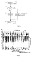
- control device for multi-stage turbochargers of the present embodiment An example of control performed by the control device for multi-stage turbochargers of the present embodiment will be explained below based on FIG. 2 .
- the control illustrated by FIG. 2 is executed by the ECU 1, for example, when the revolution speed of engine 2 is increased.
- the ECU 1 controls the variable vane 64 on the basis of the stationary-state opening degree map.
- step S1 the ECU 1 acquires a boost pressure detected by the boost sensor 12 attached to an intake air outlet (discharge port) of the low-pressure stage compressor 71 disposed in the second stage.
- step S2 the ECU 1 determines whether the boost pressure (detection value) of the boost sensor 12 acquired in step S1 exceeds a predetermined target boost pressure (predetermined value).
- the ECU 1 reads the target boost pressure from the target map stored in the ECU 1 and compares this target boost pressure with a boost pressure detected by the boost sensor 12. For example, a target boost pressure for each operation state of the engine 2 (engine revolution speed or fuel injection amount) is recorded in the target map.
- step S2 If it is determined in step S2 that the boost pressure exceeds the target boost pressure, the ECU 1 selects in step S3 the stationary-state opening degree map (standard VGT map in FIG. 2 ) in which the opening degree of the variable valve 64 in the stationary state of the engine is recorded and sets the selected map as the target VGT map in step S4.
- the stationary-state opening degree map standard VGT map in FIG. 2
- step S2 determines whether the boost pressure is equal to or lower than the target boost pressure. If it is determined in step S2 that the boost pressure is equal to or lower than the target boost pressure, the ECU 1 selects in step S5 the transient-state opening degree map (transient-state VGT map in FIG. 2 ) in which the opening degree is set lower than in the stationary-state opening degree map and sets the selected map as the target VGT map in step S4.
- the transient-state opening degree map transient-state VGT map in FIG. 2
- step S4 the stationary-state opening degree map or the transient-state opening degree map is set as the target VGT map and then the opening degree of the variable valve 64 is controlled by the ECU 1 on the basis of the target VGT map.
- the stationary-state opening degree map or the transient-state opening degree map is selected correspondingly to the boost pressure (detection value of the boost sensor 12) of the low-pressure stage turbocharger 7 so as to determine the opening degree (VGT opening degree) of the variable vane 64 of the high-pressure stage turbocharger 6.
- the opening degree of the variable vane 64 of the high-pressure stage turbocharger 6 is controlled on the basis of the transient-stage opening degree map in which the opening degree is reduced for a transient state, and when the target boost is reached, the control is performed on the basis of the stationary-state opening degree map for a stationary state even in the transient state.
- the opening degree of the variable vane 64 has been reduced more than necessary, thereby causing worsening of fuel consumption as shown in FIG. 7 .
- the effect obtained in the present embodiment is that by appropriately selecting an effective turbo VGT map on the basis of boost pressure of the low-pressure stage compressor 71, it is possible to avoid the unnecessary reduction in the opening degree of the variable vane 64 and improve fuel consumption in a two-stage turbo system.
- a total pressure ratio of the two-stage turbo system increases more than necessary and fuel consumption worsens, as shown at and after 56 sec in FIG. 5 .
- the transient-state opening degree map increases more than necessary and fuel consumption worsens, as shown at and after 56 sec in FIG. 5 .
- the excess increase in the total pressure ratio can be inhibited, as shown at and after 56 sec in FIG. 4 .
- the total pressure ratio exceeds the single-stage supercharged pressure ratio and the desirable performance requirements are satisfied.
- the VGT opening degree of the turbocharger 6 in a transient state with severe variations, is actuated in a 48 to 52 sec state of FIG. 5 to respond to severe NOx-PM, and the VGT opening degree of the turbocharger 6 in a state with more gentle variations and a stationary state is actuated in a state at and after 56 sec of FIG. 4 , thereby improving fuel consumption.
- FIG. 4 and FIG. 5 show the results of simulation test performed to evaluate a portion of the aforementioned JE05 mode.
- a typical control system using the boost sensor 12 or maf sensor 11 is employed, but the difference is that the control device of the present embodiment detects a boost pressure (turbo pressure) of the second stage (low-pressure stage) and determines the VGT opening degree of the turbocharger 6 disposed in the first stage (high-pressure stage) to solve the problem of a pressure increase lag in the turbocharger 7 disposed in the second stage (low-pressure stage), which is a unique problem of two-stage turbo systems.
- a detection value of the boost sensor 12 is used, but this is not limiting, and a detection value of the maf sensor 11 may be also used.
- the ECU 1 may control the opening degree of the variable valve 64 on the basis of the stationary-state opening degree map, and when the detected intake air amount is equal to or lower than the target air intake amount, the opening degree of the variable valve 64 may be controlled based on the transient-state opening degree map.
- control device in accordance with the present invention is applied to a two-stage system, but the structure of the control device is not limited to that shown in FIG. 1 and can be applied to all the systems using two turbochargers per engine and also to turbo systems in which three or more turbochargers are disposed in series.
Landscapes
- Engineering & Computer Science (AREA)
- Chemical & Material Sciences (AREA)
- Combustion & Propulsion (AREA)
- Mechanical Engineering (AREA)
- General Engineering & Computer Science (AREA)
- Supercharger (AREA)
- Combined Controls Of Internal Combustion Engines (AREA)
Abstract
Description
- The present invention relates to a control device for multi-stage turbochargers in which turbochargers of at least two stages are provided in series.
- In recent years, exhaust gas standards for automobile engines have been getting more stringent from year to year, methods for engine evaluation have also been getting more demanding, and methods for performing evaluation during start and acceleration have been introduced. As specific evaluation methods, a JE05 mode has been implemented in Japan and an ETC mode has been implemented in Europe (EC).
- Exhaust gas standards widely use nitrogen oxide (referred to hereinbelow as NOx) and diesel particulate (referred to hereinbelow as PM) values, but because of a trade-off relationship therebetween, it is extremely difficult to decrease both.
- Presently, effective means for meeting the exhaust gas standards include the decrease in amount of NOx by a high exhaust gas recirculation (referred to hereinbelow as EGR) and the decrease in PM by ensuring a high lambda (extra intake coefficient λ). To meet both requirements, it is necessary to use a system that ensures a high lambda over the entire engine range (entire operation range), that is, a system that can supply high overcharge to the engine.
-
FIG. 3 illustrates a transient (JE05 mode) operation mode adapted in Japan and test data. Time (sec) is plotted against the abscissa, and smoke - lambda - engine revolution speed are plotted in the order of description from below on the ordinate. - As shown in
FIG. 3 , where a vehicle is started from an engine idle state, that is, from a state in which the vehicle has been stopped, the engine revolution speed rises rapidly when the vehicle is started. At this time, the amount of intake air is temporarily insufficient and lambda rapidly drops close to 1. As a result, a large amount of smoke is discharged. - A two-stage turbo system can be considered as a system capable of supplying high supercharge to an engine with the object of satisfying the above-described exhaust gas standards.
- A two-stage turbo system is basically a system in which by disposing two turbochargers for an engine, it is possible to realize a supercharge that is higher than that in the conventional single turbo engine over the entire engine operation range.
- In such two-stage turbo system, a high supercharge is realized by performing two-stage supercharging with two turbochargers (see
Patent Documents 1 and 2). -
- Patent Document 1: Japanese Patent Application Laid-open No.
2004-225586 - Patent Document 2: Japanese Patent Application Laid-open No.
2005-315163 - However, the problem associated with the two-stage turbo system is that a pressure increase lag occurs in a turbocharger disposed in a low-pressure stage (rear stage) in a rise period e.g. in a transient test mode.
-
FIG. 4 shows comparison results on a turbo pressure (boost pressure) rise of a single-turbo system and a two-stage turbo system in a transient period. - Thus, a boost that was naturally sufficiently obtained in engine stationary operation cannot be sufficiently attained in a transient mode.
- For example, where settings with the best NOx-PM (SM) and fuel consumption are found in advance in a stationary test, a performance map such as that of Table 1 is produced, and a transient performance test is performed using the performance map such as that of Table 1, a turbo lag occurs in the transient test and NOx-PM cannot reach the target value.
- Accordingly, in the transient mode, in order to match the target exhaust gas value, a variable vane (VGT) of the turbo disposed in the first stage (high-pressure stage) can be controlled with a map (see Table 2) in which an opening degree is further reduced with respect to that of the map (see Table 1) obtained in the stationary test.
-
[Table 1] TR B TR G 5 00 6 00 7 00 8 00 9 00 10 00 11 00 12 00 13 00 14 00 15 00 16 00 17 00 18 00 19 00 20 00 0 1 0 1 0 1 5 2 0 2 5 30 33. 75 37. 5 41. 25 45 50 55 62. 5 70 80 90 20 1 0 1 0 1 5 2 0 2 5 30 33. 75 37. 5 41. 25 45 50 55 62. 5 70 80 90 40 1 0 1 0 1 5 2 0 2 5 30 33. 75 37. 5 41. 25 45 50 55 62. 5 70 80 90 60 1 0 1 0 1 5 2 0 2 5 30 33. 75 37. 5 41. 25 45 50 55 62. 5 70 80 90 80 1 0 1 0 1 5 2 0 2 5 30 33. 75 37. 5 41. 25 45 50 55 62. 5 70 80 90 10 0 1 0 1 0 1 5 2 0 2 5 30 33. 75 37. 5 41. 25 45 50 55 62. 5 70 80 90 12 0 1 0 1 0 1 5 2 0 2 5 30 33. 75 37. 5 41. 25 45 50 55 62. 5 70 80 90 14 0 1 0 1 0 1 5 2 0 2 5 30 33. 75 37. 5 41. 25 45 50 55 62. 5 70 80 90 16 0 1 0 1 0 1 5 2 0 2 5 30 33. 75 37. 5 41. 25 45 50 55 62. 5 70 80 90 18 0 1 0 1 0 1 5 2 0 2 5 30 33. 75 37. 5 41. 25 45 56. 25 62. 5 68. 5 75 82. 5 90 20 0 1 0 1 0 1 5 2 0 2 5 30 33. 75 37. 5 47. 5 55 62. 5 70 75 80 85 90 22 0 1 0 1 0 1 5 2 0 2 5 30 33. 75 37. 5 47. 5 55 62. 5 70 75 80 85 90 24 0 1 0 1 0 1 5 2 0 2 5 30 33. 75 37. 5 47. 5 55 62. 5 70 75 80 85 90 26 0 1 0 1 0 1 5 2 0 2 5 30 33. 75 37. 5 47. 5 55 62. 5 70 75 80 85 90 31 0 1 0 1 0 1 5 2 0 2 5 30 33. 75 37. 5 47. 5 55 62. 5 70 75 80 85 90 -
[Table 2] T R B T R G 5 00 6 00 70 0 8 00 90 0 10 00 110 0 12 00 130 0 14 00 150 0 16 00 170 0 18 00 19 00 20 00 0 7 7 10 .5 1 4 17 .5 21 23. 625 26. 25 28. 875 31 .5 39. 375 38. 5 43. 75 49 56 63 20 7 7 10 .5 1 4 17 .5 21 23. 625 26. 25 28. 875 31 .5 39. 375 38. 5 43. 75 49 56 63 40 7 7 10 .5 1 4 17 .5 21 23. 625 26. 25 28. 875 31 .5 39. 375 38. 5 43. 75 49 56 63 60 7 7 10 .5 1 4 17 .5 21 23. 625 26. 25 28. 875 31 .5 39. 375 38. 5 43. 75 49 56 63 80 7 7 10 .5 1 4 17 .5 21 23. 625 26. 25 28. 875 31 .5 39. 375 38. 5 43. 75 49 56 63 10 0 7 7 10 .5 1 4 17 .5 21 23. 625 26. 25 28. 875 31 .5 39. 375 38. 5 43. 75 49 56 63 12 0 7 7 10 .5 1 4 17 .5 21 23. 625 26. 25 28. 875 31 .5 39. 375 38. 5 43. 75 49 56 63 14 0 7 7 10 .5 1 4 17 .5 21 23. 625 26. 25 28. 875 31 .5 39. 375 38. 5 43. 75 49 56 63 16 0 7 7 10 .5 1 4 17 .5 21 23. 625 26. 25 28. 875 31 .5 39. 375 38. 5 43. 75 49 56 63 18 0 7 7 10 .5 1 4 17 .5 21 23. 625 26. 25 28. 875 31 .5 39. 375 43. 75 48. 125 52 .5 57. 75 63 20 0 7 7 10 .5 1 4 17 .5 21 23. 625 26. 25 33. 25 38 .5 43. 75 49 52. 5 56 59. 5 63 22 0 7 7 10 .5 1 4 17 .5 21 23. 625 26. 25 33. 25 38 .5 43. 75 49 52. 5 56 59. 5 63 24 0 7 7 10 .5 1 4 17 .5 21 23. 625 26. 25 33. 25 38 .5 43. 75 49 52. 5 56 59. 5 63 26 0 7 7 10 .5 1 4 17 .5 21 23. 625 26. 25 33. 25 38 .5 43. 75 49 52. 5 56 59. 5 63 31 0 7 7 10 .5 1 4 17 .5 21 23. 625 26. 25 33. 25 38 .5 43. 75 49 52. 5 56 59. 5 63 - Thus, as shown in
FIG. 5 , the pressure increase of the entire two-stage turbo system can be accelerated with respect to that of a single turbo. - As a result, as shown in
FIG. 6 , the trade-off of NOx-PM in the exhaust gas is improved and a target exhaust gas level is reached. - The target exhaust level can thus be reached by changing the opening degree of a variable vane (VGT) of a high-pressure stage turbocharger disposed in the first stage to that of the map of Table 2 in which the opening degree of a variable vane (VGT opening degree) is reduced with respect to that of the VGT base map shown in Table 1 and improving the rise of boost pressure.
- However, the problem is that where the opening degree of the variable vane is reduced, fuel consumption is worsened, as shown in
FIG. 7 . -
FIG. 7 shows fuel consumption results of a total test simulating the aforementioned JE05 mode. The total test includes not only a test in a transient state, but also a test in a state with gradual changes, that is, in a stationary state. - Where a map with reduced opening degree of variable vane of Table 2 is used in the test shown in
FIG. 7 , the opening degree in the turbo map is reduced more than necessary in the stationary state and the intake air is unnecessarily supplied and pressurized, thereby worsening fuel consumption. Further, even in the transient state, the opening degree in the turbo map is reduced more than necessary, thereby causing worsening of fuel consumption. - In this case, using a transient-stage map (Table 2) for bringing the NOx-PM performance in the transient test to a target value worsens fuel consumption, but this effect is stronger in the stationary state than in the transient state.
- As described above, a problem of worsened fuel consumption arises when only the decrease in NOx-PM is taken into account and the opening degree of variable vane is constantly reduced in the transient and stationary states in a transient mode.
- Accordingly, it is an object of the present invention to resolve the above-described problems and provide a control device for multi-stage turbochargers that can improve fuel consumption in the transient and stationary states of an engine equipped with multi-stage turbochargers.
- In order to attain the above-described object, the present invention provides a control device for multi-stage turbochargers which are turbochargers of at least two or more stages provided in series at an engine and in which a high-pressure stage turbocharger is configured by a variable-capacity turbocharger equipped with a variable vane, comprising: detection means for detecting a boost pressure or an intake air amount of a turbocharger of a stage with a pressure lower than that of the variable-capacity turbocharger, wherein an opening degree of the variable vane is controlled on the basis of a detection value of the detection means.
- It is preferred that the control device comprise storage means for storing a stationary-state opening degree map in which the opening degree of the variable vane in a stationary state of the engine is recorded and a transient-state opening degree map in which the opening degree is set lower than that in the stationary-state opening degree map, wherein in the stationary state of the engine, the opening degree of the variable vane is controlled based on the stationary-state opening degree map, and in the transient state of the engine, when the detection value of the detection means exceeds a predetermined value, the opening degree of the variable vane is controlled based on the stationary-state opening degree map, and when the detection value is equal to or lower than the predetermined value, the opening degree of the variable vane is controlled based on the transient-state opening degree map.
- In order to attain the above-described object, the present invention provides a control device for multi-stage turbochargers which are turbochargers of at least two or more stages provided in series at an engine and in which a high-pressure stage turbocharger is configured by a variable-capacity turbocharger equipped with a variable vane and an opening degree of the variable vane is reduced with respect to an opening degree in a stationary state when the engine revolution speed is increased, comprising: detection means for detecting a boost pressure or an intake air amount of a turbocharger of a stage with a pressure lower than that of the variable-capacity turbocharger; and prohibition means for prohibiting a reduction of the opening degree of the variable vane when a detection value of the detection means exceeds a predetermined value even when the engine revolution speed is increased.
- The present invention demonstrates an excellent effect of enabling the improvement of fuel consumption in transient and stationary states of an engine equipped with multi-stage turbochargers.
-
-
FIG. 1 is a schematic diagram of a control device for multi-stage turbochargers of an embodiment of the present invention and an engine. -
FIG. 2 is an operation system of the present embodiment. -
FIG. 3 shows test data of Japan JE05 mode. -
FIG. 4 serves to explain the comparison of turbo pressure ratio increase in a transient state. -
FIG. 5 serves to explain the comparison of turbo pressure ratio increase in a transient state in which an opening degree of high-pressure stage turbo VGT has been reduced. -
FIG. 6 serves to explain exhaust gas performance improvement results. -
FIG. 7 serves to explain how a VGT opening degree map variation worsens fuel consumption. -
- 1
- ECU (control device for multi-stage turbochargers, prohibition means)
- 2
- engine
- 6
- high-pressure stage turbocharger (variable-capacity turbocharger)
- 7
- low-pressure stage turbocharger
- 11
- maf sensor (detection means for detecting intake air amount)
- 12
- boost sensor (detection means for detecting boost pressure)
- 14
- storage means
- 64
- variable vane
- A preferred embodiment of the present invention will be described below with reference to the appended drawings.
- A control device for multi-stage turbochargers of the present embodiment is designed, for example, for a two-stage turbo system mounted on a diesel engine (referred to hereinbelow as "engine") of a vehicle.
- A schematic structure of the engine will be described based on
FIG. 1 . - As shown in
FIG. 1 , anengine 2 includes anengine body 3 having a plurality of cylinders, anintake passage 4 and anexhaust passage 5 connected to theengine body 3,turbochargers intake passage 4 andexhaust passage 5 and serving to supply supercharged air to theengine body 3, an EGR device 8 for returning part of exhaust gas of theexhaust passage 5 to theintake passage 4, and an engine control unit (referred to hereinbelow as ECU) 1 for controlling theengine body 3. - In the present embodiment, the high-pressure stage turbocharger (HP) 6 and the low-pressure stage turbocharger (LP) 7 are provided in series and configure a two-stage system.
- A
maf sensor 11, a compressor (LPC, referred to hereinbelow as low-pressure stage compressor) 71 of the low-pressure stage turbocharger 7, aboost sensor 12, a compressor (HPC, referred to hereinbelow as high-pressure stage compressor) 61 of the high-pressure stage turbocharger 6, and an air cooler (A/C) 31 are provided in the order of description from the upstream side in theintake passage 4. A downstream end of theintake passage 4 is connected to an air intake manifold (not shown in the figure) of theengine body 3. - An upstream end of the
exhaust passage 5 is connected to an exhaust manifold (not shown in the figure) of theengine body 3. A turbine (HPT, referred to hereinbelow as high-pressure stage turbine) 62 of the high-pressure stage turbocharger 6 and a turbine (LPT, referred to hereinbelow as low-pressure stage turbine) 72 of the low-pressure stage turbocharger 7 are provided in the order of description from the upstream side in theexhaust passage 5. - The low-
pressure stage turbocharger 7 includes the above-described low-pressure stage compressor 71 and low-pressure stage turbine 72 and aturbine shaft 73 that couples the low-pressure stage compressor 71 and the low-pressure stage turbine 72. The low-pressure stage compressor 71 is driven by the low-pressure stage turbine 72 and pressurizes the intake air. - The
maf sensor 11 disposed upstream of the low-pressure stage compressor 71 is detection means for detecting an intake air amount (mass flow rate) taken in the low-pressure stage compressor 71, and theboost sensor 12 attached to a discharge port of the low-pressure stage compressor 71 is detection means for detecting a boost pressure of the low-pressure stage compressor 71. - The high-
pressure stage turbocharger 6 includes the above-described high-pressure stage compressor 61 and high-pressure stage turbine 62 and aturbine shaft 63 that couples the high-pressure stage compressor 61 and the high-pressure stage turbine 62. The high-pressure stage compressor 61 is driven by the high-pressure stage turbine 62, further pressurizes the supercharged air pressurized in the low-pressure stage compressor 71, and supplies it to theengine body 3. - In the present embodiment, the high-
pressure stage turbocharger 6 is configured by a variable-capacity turbocharger (in the figure, electronically controlled VGS) equipped with avariable vane 64. - More specifically, the high-pressure stage turbine 62 is provided with the
variable vane 64 for changing the turbine capacity, and the high-pressure stage turbine 62 is so configured that where an opening degree of thevariable vane 64 is reduced, the turbine capacity is decreased. - A
wastegate unit 65 for bypassing the high-pressure stage turbine 62 is provided in the high-pressure stage turbocharger 6. Thewastegate unit 65 includes a wastegate passage 651 for linking an upstream side (intake side) and a downstream side (discharge side) of the high-pressure stage turbine 62 and awastegate valve 652 provided in the wastegate passage 651. - The EGR device 8 includes an
EGR passage 81 for linking theexhaust passage 5 and theintake passage 4, anEGR valve 82 provided in theEGR passage 81, and anEGR cooler 83 that is disposed upstream of theEGR valve 82 and serves for cooling a gas (EGR gas) flowing in theEGR passage 81. The upstream end of theEGR passage 81 is connected to theexhaust passage 5 between theengine body 3 and the high-pressure side turbine, and the downstream end is connected to theintake passage 4 between theengine body 3 andair cooler 31. - The
ECU 1 of the present embodiment is a control unit of themulti-stage turbocharger 6 and controls an opening degree of thevariable vane 64 of the high-pressure stage turbine 62 on the basis of a detection value (intake air amount of the low-pressure stage turbine 72) of the maf sensor or a detection value (boost pressure of the low-pressure stage turbine 72) of theboost sensor 12. - Various sensors such as the
maf sensor 11 and theboost sensor 12 are connected to theECU 1 and detection values of these sensors are inputted therein. - Further, the
ECU 1 is connected so as to supply control signals to various actuators such as thewastegate valve 652 andvariable vane 64 of the high-pressure stage turbine 62. - The
ECU 1 includes storage means 14 that stores a stationary-state opening degree map (see Table 1) in which an opening degree of thevariable vane 64 in a stationary state of theengine 2 is set and a transient-state opening degree map (see Table 2) in which the opening degree is set lower than that in the stationary-state opening degree map. In the stationary state of theengine 2, an opening degree of thevariable vane 64 is controlled based on the stationary-state opening degree map, and in the transient state of theengine 2, when the detection value of the detection means 11, 12 exceeds a predetermined value, an opening degree of thevariable vane 64 is controlled based on the stationary-state opening degree map, and when the detection value is equal to or lower than the predetermined value, an opening degree of thevariable vane 64 is controlled based on the transient-state opening degree map. These configuration and operation will be described below in greater detail. - Here, in the stationary-state opening degree map of Table 1 and the transient-state opening degree map of Table 2, an engine revolution speed (rpm) is plotted against the abscissa (first line), and a fuel flow rate (mm3/st) is plotted against the ordinate. Further, numerical values in the tables indicate an opening degree (%) of the
variable vane 64, and the smaller is the numerical value, the more closed (reduced) is thevariable vane 64. - Control performed by the control device for multi-stage turbochargers of the present embodiment will be descried below.
- In a transient state, for example when the revolution speed of the
engine 2 is increased, theECU 1 of the present embodiment basically reduces the opening degree of thevariable vane 64 of the high-pressure stage turbine 62 with respect to that in a stationary state so as to prevent a pressure increase lag of the low-pressure stage turbocharger 7. - The stationary state as referred to herein is a state with smallest variations in engine operation state, for example, a state in which the vehicle travels at a constant speed (or a state in which the engine revolves at a constant rate), and the transient state is a state with most severe variations in engine operation state, for example, a state in which the vehicle accelerates (or a state in which the engine revolution speed rises).
- However, there is a concern that reducing the opening degree of the
variable vane 64 of the high-pressure stage turbine 62 will cause deterioration of fuel consumption. - Accordingly, in the present embodiment, inhibition means is provided for inhibiting a reduction of the opening degree of the
variable vane 64 when the detection value of the detection means 11, 12 exceeds a predetermined value even in a transient state, for example when the revolution speed ofengine 2 is increased. In the present embodiment,ECU 1 constitutes the inhibition means. - More specifically, the
ECU 1 of the present embodiment holds a transient-state opening degree map for a transient state and a stationary-state opening degree map for a stationary state as control maps of the variable vane 64 (VGT) of the high-pressure stage turbocharger 6 that is disposed in the first stage and switches a control map of thevariable vane 64 of the high-pressure stage turbocharger 6 that is disposed in the first stage between the stationary-state opening degree map and the transient-state opening degree map, depending on a degree to which a boost pressure or intake air amount of the low-pressure stage turbocharger 7 disposed in the second stage has reached the target map, in order to improve the deterioration of fuel consumption in a transient state in the two-stage turbo system. - As a result, the unnecessary reduction in opening degree of the
variable vane 64 in a transient state can be prevented and fuel consumption can be improved. - An example of control performed by the control device for multi-stage turbochargers of the present embodiment will be explained below based on
FIG. 2 . - The control illustrated by
FIG. 2 is executed by theECU 1, for example, when the revolution speed ofengine 2 is increased. In a stationary state ofengine 2, theECU 1 controls thevariable vane 64 on the basis of the stationary-state opening degree map. - In step S1, the
ECU 1 acquires a boost pressure detected by theboost sensor 12 attached to an intake air outlet (discharge port) of the low-pressure stage compressor 71 disposed in the second stage. - In step S2, the
ECU 1 determines whether the boost pressure (detection value) of theboost sensor 12 acquired in step S1 exceeds a predetermined target boost pressure (predetermined value). - More specifically, the
ECU 1 reads the target boost pressure from the target map stored in theECU 1 and compares this target boost pressure with a boost pressure detected by theboost sensor 12. For example, a target boost pressure for each operation state of the engine 2 (engine revolution speed or fuel injection amount) is recorded in the target map. - If it is determined in step S2 that the boost pressure exceeds the target boost pressure, the
ECU 1 selects in step S3 the stationary-state opening degree map (standard VGT map inFIG. 2 ) in which the opening degree of thevariable valve 64 in the stationary state of the engine is recorded and sets the selected map as the target VGT map in step S4. - On the other hand, if it is determined in step S2 that the boost pressure is equal to or lower than the target boost pressure, the
ECU 1 selects in step S5 the transient-state opening degree map (transient-state VGT map inFIG. 2 ) in which the opening degree is set lower than in the stationary-state opening degree map and sets the selected map as the target VGT map in step S4. - In step S4, the stationary-state opening degree map or the transient-state opening degree map is set as the target VGT map and then the opening degree of the
variable valve 64 is controlled by theECU 1 on the basis of the target VGT map. - Thus, in the present embodiment, the stationary-state opening degree map or the transient-state opening degree map is selected correspondingly to the boost pressure (detection value of the boost sensor 12) of the low-
pressure stage turbocharger 7 so as to determine the opening degree (VGT opening degree) of thevariable vane 64 of the high-pressure stage turbocharger 6. - In other words, when the boost pressure of the low-
pressure stage turbocharger 7 does not reach the target boost pressure in a transient state, the opening degree of thevariable vane 64 of the high-pressure stage turbocharger 6 is controlled on the basis of the transient-stage opening degree map in which the opening degree is reduced for a transient state, and when the target boost is reached, the control is performed on the basis of the stationary-state opening degree map for a stationary state even in the transient state. - As a result, in the present embodiment, it is possible to improve fuel consumption in a transient state of the
engine 2 provided with themulti-stage turbochargers 6. - Thus, because the transient-state opening degree map shown in the table has been conventionally used at all times in the transient state, the opening degree of the
variable vane 64 has been reduced more than necessary, thereby causing worsening of fuel consumption as shown inFIG. 7 . - By contrast, the effect obtained in the present embodiment is that by appropriately selecting an effective turbo VGT map on the basis of boost pressure of the low-
pressure stage compressor 71, it is possible to avoid the unnecessary reduction in the opening degree of thevariable vane 64 and improve fuel consumption in a two-stage turbo system. - For example, when only the transient-state opening degree map is used, as in the conventional system, a total pressure ratio of the two-stage turbo system increases more than necessary and fuel consumption worsens, as shown at and after 56 sec in
FIG. 5 . By contrast, in the present embodiment, because switching is performed from the transient-state opening degree map to the stationary-state opening degree map on the basis of boost pressure, the excess increase in the total pressure ratio can be inhibited, as shown at and after 56 sec inFIG. 4 . Further, in this case, the total pressure ratio exceeds the single-stage supercharged pressure ratio and the desirable performance requirements are satisfied. - Thus, in the present embodiment, in a transient state with severe variations, the VGT opening degree of the
turbocharger 6 is actuated in a 48 to 52 sec state ofFIG. 5 to respond to severe NOx-PM, and the VGT opening degree of theturbocharger 6 in a state with more gentle variations and a stationary state is actuated in a state at and after 56 sec ofFIG. 4 , thereby improving fuel consumption. -
FIG. 4 and FIG. 5 show the results of simulation test performed to evaluate a portion of the aforementioned JE05 mode. - In this case, a typical control system using the
boost sensor 12 ormaf sensor 11 is employed, but the difference is that the control device of the present embodiment detects a boost pressure (turbo pressure) of the second stage (low-pressure stage) and determines the VGT opening degree of theturbocharger 6 disposed in the first stage (high-pressure stage) to solve the problem of a pressure increase lag in theturbocharger 7 disposed in the second stage (low-pressure stage), which is a unique problem of two-stage turbo systems. - The present invention is not limited to the above-described embodiment and a variety of modification examples or application examples can be considered.
- For example, a detection value of the
boost sensor 12 is used, but this is not limiting, and a detection value of themaf sensor 11 may be also used. Thus, when the intake air amount detected by themaf sensor 11 exceeds the predetermined target intake air amount in a transient state of theengine 2, theECU 1 may control the opening degree of thevariable valve 64 on the basis of the stationary-state opening degree map, and when the detected intake air amount is equal to or lower than the target air intake amount, the opening degree of thevariable valve 64 may be controlled based on the transient-state opening degree map. - Further, in the above-described embodiment, the control device in accordance with the present invention is applied to a two-stage system, but the structure of the control device is not limited to that shown in
FIG. 1 and can be applied to all the systems using two turbochargers per engine and also to turbo systems in which three or more turbochargers are disposed in series.
Claims (3)
- A control device for multi-stage turbochargers which are turbochargers of at least two or more stages provided in series at an engine and in which a high-pressure stage turbocharger is configured by a variable-capacity turbocharger equipped with a variable vane, comprising:detection means for detecting a boost pressure or an intake air amount of a turbocharger of a stage with a pressure lower than that of the variable-capacity turbocharger, wherein an opening degree of the variable vane is controlled on the basis of a detection value of the detection means.
- The control device for multi-stage turbochargers according to claim 1, comprising:storage means for storing a stationary-state opening degree map in which the opening degree of the variable vane in a stationary state of the engine is recorded and a transient-state opening degree map in which the opening degree is set lower than that in the stationary-state opening degree map, whereinin the stationary state of the engine, the opening degree of the variable vane is controlled based on the stationary-state opening degree map, and in the transient state of the engine, when the detection value of the detection means exceeds a predetermined value, the opening degree of the variable vane is controlled based on the stationary-state opening degree map, and when the detection value is equal to or lower than the predetermined value, the opening degree of the variable vane is controlled based on the transient-state opening degree map.
- A control device for multi-stage turbochargers which are turbochargers of at least two or more stages provided in series at an engine and in which a high-pressure stage turbocharger is configured by a variable-capacity turbocharger equipped with a variable vane and an opening degree of the variable vane is reduced with respect to an opening degree in a stationary state when the engine revolution speed is increased, comprising:detection means for detecting a boost pressure or an intake air amount of a turbocharger of a stage with a pressure lower than that of the variable-capacity turbocharger; andprohibition means for prohibiting a reduction of the opening degree of the variable vane when a detection value of the detection means exceeds a predetermined value even when the engine revolution speed is increased.
Applications Claiming Priority (2)
| Application Number | Priority Date | Filing Date | Title |
|---|---|---|---|
| JP2006245401A JP4067025B2 (en) | 2006-09-11 | 2006-09-11 | Multistage turbocharger controller |
| PCT/JP2007/067485 WO2008032649A1 (en) | 2006-09-11 | 2007-09-07 | Control device for multi-stage turbochargers |
Publications (3)
| Publication Number | Publication Date |
|---|---|
| EP2063083A1 true EP2063083A1 (en) | 2009-05-27 |
| EP2063083A4 EP2063083A4 (en) | 2011-07-13 |
| EP2063083B1 EP2063083B1 (en) | 2013-05-01 |
Family
ID=39183708
Family Applications (1)
| Application Number | Title | Priority Date | Filing Date |
|---|---|---|---|
| EP07806926.7A Not-in-force EP2063083B1 (en) | 2006-09-11 | 2007-09-07 | Control device for multi-stage turbochargers |
Country Status (5)
| Country | Link |
|---|---|
| US (1) | US8176735B2 (en) |
| EP (1) | EP2063083B1 (en) |
| JP (1) | JP4067025B2 (en) |
| CN (1) | CN101548084B (en) |
| WO (1) | WO2008032649A1 (en) |
Cited By (2)
| Publication number | Priority date | Publication date | Assignee | Title |
|---|---|---|---|---|
| DE102010010480A1 (en) * | 2010-03-06 | 2011-09-08 | Volkswagen Ag | Internal combustion engine with two-stage supercharging |
| CN102673347A (en) * | 2011-03-18 | 2012-09-19 | 三菱重工业株式会社 | Heat medium heating apparatus and vehicular air-conditioning system including same |
Families Citing this family (70)
| Publication number | Priority date | Publication date | Assignee | Title |
|---|---|---|---|---|
| JP4067025B2 (en) * | 2006-09-11 | 2008-03-26 | いすゞ自動車株式会社 | Multistage turbocharger controller |
| JP2010138710A (en) * | 2008-12-09 | 2010-06-24 | Hino Motors Ltd | Two-stage supercharging system |
| JP2010180782A (en) * | 2009-02-05 | 2010-08-19 | Isuzu Motors Ltd | Multistage supercharging system of internal combustion engine and method of controlling the same |
| EP2752565B1 (en) * | 2009-03-06 | 2018-12-12 | Toyota Jidosha Kabushiki Kaisha | Multistage supercharging system control apparatus |
| JP5282629B2 (en) * | 2009-03-31 | 2013-09-04 | トヨタ自動車株式会社 | Internal combustion engine system control device |
| US8640459B2 (en) * | 2009-10-23 | 2014-02-04 | GM Global Technology Operations LLC | Turbocharger control systems and methods for improved transient performance |
| JP5630025B2 (en) * | 2010-01-25 | 2014-11-26 | いすゞ自動車株式会社 | Diesel engine exhaust purification device and exhaust purification method |
| JP2012077730A (en) * | 2010-10-06 | 2012-04-19 | Hino Motors Ltd | Two-stage supercharging system |
| JP5874161B2 (en) * | 2010-10-28 | 2016-03-02 | いすゞ自動車株式会社 | Turbocharger system |
| CN102562273B (en) * | 2012-02-13 | 2014-01-08 | 清华大学 | Turbine composite device with variable geometry charging turbine and engine system thereof |
| US9534547B2 (en) | 2012-09-13 | 2017-01-03 | GM Global Technology Operations LLC | Airflow control systems and methods |
| JP6026211B2 (en) * | 2012-10-11 | 2016-11-16 | 日野自動車株式会社 | Turbocharger control device and control method |
| US9435274B2 (en) | 2014-03-26 | 2016-09-06 | GM Global Technology Operations LLC | System and method for managing the period of a control loop for controlling an engine using model predictive control |
| US9378594B2 (en) | 2014-03-26 | 2016-06-28 | GM Global Technology Operations LLC | Fault diagnostic systems and methods for model predictive control |
| US9382865B2 (en) | 2014-03-26 | 2016-07-05 | GM Global Technology Operations LLC | Diagnostic systems and methods using model predictive control |
| US9784198B2 (en) | 2015-02-12 | 2017-10-10 | GM Global Technology Operations LLC | Model predictive control systems and methods for increasing computational efficiency |
| US9765703B2 (en) | 2013-04-23 | 2017-09-19 | GM Global Technology Operations LLC | Airflow control systems and methods using model predictive control |
| US9388758B2 (en) | 2014-03-26 | 2016-07-12 | GM Global Technology Operations LLC | Model predictive control systems and methods for future torque changes |
| US9429085B2 (en) * | 2013-04-23 | 2016-08-30 | GM Global Technology Operations LLC | Airflow control systems and methods using model predictive control |
| US9388754B2 (en) | 2014-03-26 | 2016-07-12 | GM Global Technology Operations LLC | Artificial output reference for model predictive control |
| US9714616B2 (en) | 2014-03-26 | 2017-07-25 | GM Global Technology Operations LLC | Non-model predictive control to model predictive control transitions |
| US9920697B2 (en) | 2014-03-26 | 2018-03-20 | GM Global Technology Operations LLC | Engine control systems and methods for future torque request increases |
| US9863345B2 (en) | 2012-11-27 | 2018-01-09 | GM Global Technology Operations LLC | System and method for adjusting weighting values assigned to errors in target actuator values of an engine when controlling the engine using model predictive control |
| US9328671B2 (en) | 2013-04-23 | 2016-05-03 | GM Global Technology Operations LLC | Airflow control systems and methods using model predictive control |
| US9587573B2 (en) | 2014-03-26 | 2017-03-07 | GM Global Technology Operations LLC | Catalyst light off transitions in a gasoline engine using model predictive control |
| US9599049B2 (en) | 2014-06-19 | 2017-03-21 | GM Global Technology Operations LLC | Engine speed control systems and methods |
| US9347381B2 (en) | 2014-03-26 | 2016-05-24 | GM Global Technology Operations LLC | Model predictive control systems and methods for internal combustion engines |
| US9243524B2 (en) | 2014-03-26 | 2016-01-26 | GM Global Technology Operations LLC | Engine control systems and methods for transmission upshifts |
| US9541019B2 (en) | 2014-03-26 | 2017-01-10 | GM Global Technology Operations LLC | Estimation systems and methods with model predictive control |
| US9605615B2 (en) | 2015-02-12 | 2017-03-28 | GM Global Technology Operations LLC | Model Predictive control systems and methods for increasing computational efficiency |
| US9797318B2 (en) | 2013-08-02 | 2017-10-24 | GM Global Technology Operations LLC | Calibration systems and methods for model predictive controllers |
| US9376965B2 (en) | 2013-04-23 | 2016-06-28 | GM Global Technology Operations LLC | Airflow control systems and methods using model predictive control |
| US9732688B2 (en) | 2014-03-26 | 2017-08-15 | GM Global Technology Operations LLC | System and method for increasing the temperature of a catalyst when an engine is started using model predictive control |
| US9528453B2 (en) | 2014-11-07 | 2016-12-27 | GM Global Technologies Operations LLC | Throttle control systems and methods based on pressure ratio |
| JP6096056B2 (en) * | 2013-05-31 | 2017-03-15 | 三菱重工業株式会社 | Denitration device control device, denitration device, and denitration device control method |
| DE102015201905A1 (en) * | 2015-02-04 | 2016-08-04 | Robert Bosch Gmbh | Method for reducing exhaust emissions in a transient transition phase of a vehicle |
| US10662903B2 (en) | 2015-02-27 | 2020-05-26 | Avl Powertrain Engineering, Inc. | Waste heat recovery and boost systems including variable drive mechanisms |
| US10072562B2 (en) * | 2015-02-27 | 2018-09-11 | Avl Powertrain Engineering, Inc. | Engine turbo-compounding system |
| US9447754B1 (en) | 2015-07-02 | 2016-09-20 | Bright Acceleration Technologies LLC | Method and apparatus for internal combustion engine system with improved turbocharging |
| US9695740B2 (en) | 2015-07-14 | 2017-07-04 | Ford Global Technologies, Llc | Methods and systems for boost control |
| US10060341B2 (en) | 2015-07-14 | 2018-08-28 | Ford Global Technologies, Llc | Methods and systems for boost control |
| US9890691B2 (en) | 2015-08-19 | 2018-02-13 | Ford Global Technologies, Llc | Method and system to reduce charge air cooler condensation |
| US10208693B2 (en) | 2015-10-28 | 2019-02-19 | Ford Global Technologies, Llc | Method and system to mitigate throttle degradation |
| US10024226B2 (en) | 2016-05-20 | 2018-07-17 | Ford Global Technologies, Llc | Method and system for boost pressure control |
| US10024227B2 (en) | 2016-05-20 | 2018-07-17 | Ford Global Technologies, Llc | Method and system for boost pressure control |
| US9890697B2 (en) | 2016-05-20 | 2018-02-13 | Ford Global Technologies, Llc | Method and system for boost pressure control |
| US9938908B2 (en) | 2016-06-14 | 2018-04-10 | GM Global Technology Operations LLC | System and method for predicting a pedal position based on driver behavior and controlling one or more engine actuators based on the predicted pedal position |
| US9789876B1 (en) | 2016-06-16 | 2017-10-17 | GM Global Technology Operations LLC | Axle torque control system for a motor vehicle |
| US10697357B2 (en) | 2016-09-01 | 2020-06-30 | Bright Acceleration Technologies LLC | Cross-port air flow to reduce pumping losses |
| US10107215B2 (en) | 2016-09-01 | 2018-10-23 | Bright Acceleration Technologies LLC | Synergistic induction and turbocharging in internal combustion engine systems |
| US10364739B2 (en) | 2016-09-01 | 2019-07-30 | Bright Acceleration Technologies LLC | Synergistic induction and turbocharging in internal combustion engine systems |
| US9638095B1 (en) | 2016-09-01 | 2017-05-02 | Bright Acceleration Technologies LLC | Synergistic induction and turbocharging in internal combustion engine systems |
| JP6764780B2 (en) * | 2016-12-26 | 2020-10-07 | 三菱重工業株式会社 | Control device for engine system and engine system |
| CN108167068A (en) * | 2017-01-06 | 2018-06-15 | 苏州意驱动汽车科技有限公司 | A kind of turbocharger electronic actuators scaling method and system |
| CN108167066A (en) * | 2017-01-06 | 2018-06-15 | 苏州意驱动汽车科技有限公司 | A kind of turbocharging control method and control system and engine |
| US10125712B2 (en) | 2017-02-17 | 2018-11-13 | GM Global Technology Operations LLC | Torque security of MPC-based powertrain control |
| US10119481B2 (en) | 2017-03-22 | 2018-11-06 | GM Global Technology Operations LLC | Coordination of torque interventions in MPC-based powertrain control |
| US10605180B2 (en) | 2017-08-31 | 2020-03-31 | Ford Global Technologies, Llc | Method and system for a boosted engine |
| US10422289B2 (en) | 2017-08-31 | 2019-09-24 | Ford Global Technologies, Llc | Method and system for a boosted engine |
| US10399574B2 (en) | 2017-09-07 | 2019-09-03 | GM Global Technology Operations LLC | Fuel economy optimization using air-per-cylinder (APC) in MPC-based powertrain control |
| US10358140B2 (en) | 2017-09-29 | 2019-07-23 | GM Global Technology Operations LLC | Linearized model based powertrain MPC |
| CN109854402A (en) * | 2017-11-30 | 2019-06-07 | 中国人民解放军陆军军事交通学院 | Diesel altitude-variable self-adapting system and its control method |
| JP7047468B2 (en) * | 2018-03-05 | 2022-04-05 | いすゞ自動車株式会社 | Turbo turbocharger, turbocharger system and turbocharger system supercharging method |
| US10619586B2 (en) | 2018-03-27 | 2020-04-14 | GM Global Technology Operations LLC | Consolidation of constraints in model predictive control |
| US10661804B2 (en) | 2018-04-10 | 2020-05-26 | GM Global Technology Operations LLC | Shift management in model predictive based propulsion system control |
| KR102588946B1 (en) * | 2018-05-28 | 2023-10-16 | 현대자동차주식회사 | Method of preventing surge for vehicle |
| US10859159B2 (en) | 2019-02-11 | 2020-12-08 | GM Global Technology Operations LLC | Model predictive control of torque converter clutch slip |
| US11312208B2 (en) | 2019-08-26 | 2022-04-26 | GM Global Technology Operations LLC | Active thermal management system and method for flow control |
| US11008921B1 (en) | 2019-11-06 | 2021-05-18 | GM Global Technology Operations LLC | Selective catalytic reduction device control |
| JP7444732B2 (en) | 2020-08-14 | 2024-03-06 | 株式会社トランストロン | Engine model construction methods, programs, and devices |
Family Cites Families (17)
| Publication number | Priority date | Publication date | Assignee | Title |
|---|---|---|---|---|
| FR1397178A (en) * | 1963-11-14 | 1965-04-30 | Nordberg Manufacturing Co | Highly supercharged internal combustion engine |
| US4292806A (en) * | 1979-02-28 | 1981-10-06 | Semco Instruments, Inc. | Turbocharger control system |
| US4292807A (en) * | 1979-05-02 | 1981-10-06 | United Technologies Corporation | Variable geometry turbosupercharger system for internal combustion engine |
| JP2526100B2 (en) * | 1988-07-18 | 1996-08-21 | 株式会社 いすゞセラミックス研究所 | Supercharger control device |
| GB9720430D0 (en) * | 1997-09-26 | 1997-11-26 | Lucas Ind Plc | Control method |
| JP3918402B2 (en) * | 2000-05-18 | 2007-05-23 | 日産自動車株式会社 | Diesel engine control device |
| JP2002317703A (en) * | 2001-04-19 | 2002-10-31 | Toyota Motor Corp | Control device for variable capacity turbocharger |
| JP3804480B2 (en) * | 2001-07-13 | 2006-08-02 | マツダ株式会社 | Diesel engine control device and control method |
| JP3979294B2 (en) | 2003-01-22 | 2007-09-19 | トヨタ自動車株式会社 | Multistage turbocharger controller |
| FR2854437B1 (en) * | 2003-05-02 | 2006-06-23 | Renault Sa | DEVICE AND METHOD FOR CONTROLLING THE SUPPLY PRESSURE IN AN INTERNAL COMBUSTION ENGINE EQUIPPED WITH A TWO STAGE TURBOCHARGER SYSTEM |
| JP4337489B2 (en) * | 2003-09-26 | 2009-09-30 | トヨタ自動車株式会社 | Supercharger |
| DE10352712A1 (en) * | 2003-11-06 | 2005-06-09 | Sumser, Siegfried, Dipl.-Ing. | Multistage air supply equipment for e.g. petrol engine of passenger car, has turbocharger with twin air flow machine on air suction side, where machine controls air inlet dosing such that choke is made superfluous |
| JP4254606B2 (en) | 2004-04-28 | 2009-04-15 | トヨタ自動車株式会社 | Multistage turbocharging system for internal combustion engines |
| JP4254612B2 (en) * | 2004-05-18 | 2009-04-15 | トヨタ自動車株式会社 | Multistage supercharging system for internal combustion engine and setting method thereof |
| US7137253B2 (en) * | 2004-09-16 | 2006-11-21 | General Electric Company | Method and apparatus for actively turbocharging an engine |
| JP4067025B2 (en) * | 2006-09-11 | 2008-03-26 | いすゞ自動車株式会社 | Multistage turbocharger controller |
| US7937996B2 (en) * | 2007-08-24 | 2011-05-10 | GM Global Technology Operations LLC | Turbo speed sensor diagnostic for turbocharged engines |
-
2006
- 2006-09-11 JP JP2006245401A patent/JP4067025B2/en not_active Expired - Fee Related
-
2007
- 2007-09-07 CN CN2007800335944A patent/CN101548084B/en active Active
- 2007-09-07 WO PCT/JP2007/067485 patent/WO2008032649A1/en not_active Ceased
- 2007-09-07 EP EP07806926.7A patent/EP2063083B1/en not_active Not-in-force
- 2007-09-07 US US12/440,612 patent/US8176735B2/en not_active Expired - Fee Related
Cited By (3)
| Publication number | Priority date | Publication date | Assignee | Title |
|---|---|---|---|---|
| DE102010010480A1 (en) * | 2010-03-06 | 2011-09-08 | Volkswagen Ag | Internal combustion engine with two-stage supercharging |
| WO2011110314A1 (en) * | 2010-03-06 | 2011-09-15 | Volkswagen Aktiengesellschaft | Internal combustion engine having two-stage supercharging |
| CN102673347A (en) * | 2011-03-18 | 2012-09-19 | 三菱重工业株式会社 | Heat medium heating apparatus and vehicular air-conditioning system including same |
Also Published As
| Publication number | Publication date |
|---|---|
| CN101548084B (en) | 2011-05-11 |
| US8176735B2 (en) | 2012-05-15 |
| JP2008064069A (en) | 2008-03-21 |
| CN101548084A (en) | 2009-09-30 |
| WO2008032649A1 (en) | 2008-03-20 |
| EP2063083A4 (en) | 2011-07-13 |
| JP4067025B2 (en) | 2008-03-26 |
| EP2063083B1 (en) | 2013-05-01 |
| US20100011763A1 (en) | 2010-01-21 |
Similar Documents
| Publication | Publication Date | Title |
|---|---|---|
| EP2063083B1 (en) | Control device for multi-stage turbochargers | |
| US6543230B1 (en) | Method for adjusting a boosted internal combustion engine with exhaust gas recirculation | |
| US8640459B2 (en) | Turbocharger control systems and methods for improved transient performance | |
| CN102213159B (en) | Internal and external LP EGR for boosted engines | |
| AU2010292821B2 (en) | System and method for operating a turbocharged engine | |
| US8096123B2 (en) | System and method for mode transition for a two-stage series sequential turbocharger | |
| RU153603U1 (en) | SUPPLY CONTROL SYSTEM | |
| US7779633B2 (en) | Method for determining the exhaust back pressure upstream of a turbine of an exhaust-driven turbocharger | |
| CN102177323B (en) | engine | |
| EP2320051B1 (en) | Emission control system for an engine having a two-stage turbocharger | |
| EP2933458B1 (en) | Engine control device | |
| EP2500556B1 (en) | Internal combustion engine control device | |
| JP5029780B2 (en) | Multistage supercharging system controller | |
| JPWO2011007455A1 (en) | Control valve abnormality determination device for internal combustion engine | |
| JP2011069305A (en) | Internal combustion engine and method for controlling the same | |
| US20060101819A1 (en) | Method and system for influencing the quantity of exhaust gas recirculated in a pressure charged internal combustion engine | |
| JP2014034959A (en) | Exhaust gas recirculation device of engine with supercharger | |
| EP2698518B1 (en) | Internal combustion engine control apparatus | |
| KR100962160B1 (en) | Boost pressure control | |
| JP4911432B2 (en) | Control device for internal combustion engine | |
| JP2010180782A (en) | Multistage supercharging system of internal combustion engine and method of controlling the same | |
| JP2005069143A (en) | Premixed compression self-ignition internal combustion engine | |
| JP2011111929A (en) | Internal combustion engine and method for controlling the same | |
| EP2644871A1 (en) | Control device for internal combustion engine | |
| JP2010138759A (en) | Supercharging system for internal combustion engine and control method therefor |
Legal Events
| Date | Code | Title | Description |
|---|---|---|---|
| PUAI | Public reference made under article 153(3) epc to a published international application that has entered the european phase |
Free format text: ORIGINAL CODE: 0009012 |
|
| 17P | Request for examination filed |
Effective date: 20090317 |
|
| AK | Designated contracting states |
Kind code of ref document: A1 Designated state(s): DE FR GB IT |
|
| AX | Request for extension of the european patent |
Extension state: AL BA HR MK RS |
|
| A4 | Supplementary search report drawn up and despatched |
Effective date: 20110615 |
|
| 17Q | First examination report despatched |
Effective date: 20120217 |
|
| DAX | Request for extension of the european patent (deleted) | ||
| GRAP | Despatch of communication of intention to grant a patent |
Free format text: ORIGINAL CODE: EPIDOSNIGR1 |
|
| GRAS | Grant fee paid |
Free format text: ORIGINAL CODE: EPIDOSNIGR3 |
|
| GRAA | (expected) grant |
Free format text: ORIGINAL CODE: 0009210 |
|
| AK | Designated contracting states |
Kind code of ref document: B1 Designated state(s): DE FR GB IT |
|
| REG | Reference to a national code |
Ref country code: GB Ref legal event code: FG4D |
|
| REG | Reference to a national code |
Ref country code: DE Ref legal event code: R096 Ref document number: 602007030202 Country of ref document: DE Effective date: 20130627 |
|
| RAP2 | Party data changed (patent owner data changed or rights of a patent transferred) |
Owner name: ISUZU MOTORS, LTD. |
|
| PG25 | Lapsed in a contracting state [announced via postgrant information from national office to epo] |
Ref country code: IT Free format text: LAPSE BECAUSE OF FAILURE TO SUBMIT A TRANSLATION OF THE DESCRIPTION OR TO PAY THE FEE WITHIN THE PRESCRIBED TIME-LIMIT Effective date: 20130501 |
|
| PLBE | No opposition filed within time limit |
Free format text: ORIGINAL CODE: 0009261 |
|
| STAA | Information on the status of an ep patent application or granted ep patent |
Free format text: STATUS: NO OPPOSITION FILED WITHIN TIME LIMIT |
|
| 26N | No opposition filed |
Effective date: 20140204 |
|
| REG | Reference to a national code |
Ref country code: DE Ref legal event code: R097 Ref document number: 602007030202 Country of ref document: DE Effective date: 20140204 |
|
| REG | Reference to a national code |
Ref country code: DE Ref legal event code: R082 Ref document number: 602007030202 Country of ref document: DE Representative=s name: SCHAUMBURG & PARTNER PATENTANWAELTE GBR, DE Ref country code: DE Ref legal event code: R082 Ref document number: 602007030202 Country of ref document: DE Representative=s name: SCHAUMBURG UND PARTNER PATENTANWAELTE MBB, DE |
|
| REG | Reference to a national code |
Ref country code: FR Ref legal event code: PLFP Year of fee payment: 9 |
|
| PGFP | Annual fee paid to national office [announced via postgrant information from national office to epo] |
Ref country code: FR Payment date: 20150811 Year of fee payment: 9 |
|
| PGFP | Annual fee paid to national office [announced via postgrant information from national office to epo] |
Ref country code: GB Payment date: 20160907 Year of fee payment: 10 Ref country code: DE Payment date: 20160831 Year of fee payment: 10 |
|
| REG | Reference to a national code |
Ref country code: FR Ref legal event code: ST Effective date: 20170531 |
|
| PG25 | Lapsed in a contracting state [announced via postgrant information from national office to epo] |
Ref country code: FR Free format text: LAPSE BECAUSE OF NON-PAYMENT OF DUE FEES Effective date: 20160930 |
|
| REG | Reference to a national code |
Ref country code: DE Ref legal event code: R119 Ref document number: 602007030202 Country of ref document: DE |
|
| GBPC | Gb: european patent ceased through non-payment of renewal fee |
Effective date: 20170907 |
|
| PG25 | Lapsed in a contracting state [announced via postgrant information from national office to epo] |
Ref country code: GB Free format text: LAPSE BECAUSE OF NON-PAYMENT OF DUE FEES Effective date: 20170907 Ref country code: DE Free format text: LAPSE BECAUSE OF NON-PAYMENT OF DUE FEES Effective date: 20180404 |