EP2062038B1 - Method and sensor for determining the passivating properties of a mixture containing at least two components, which are cement and water - Google Patents
Method and sensor for determining the passivating properties of a mixture containing at least two components, which are cement and water Download PDFInfo
- Publication number
- EP2062038B1 EP2062038B1 EP06793420.8A EP06793420A EP2062038B1 EP 2062038 B1 EP2062038 B1 EP 2062038B1 EP 06793420 A EP06793420 A EP 06793420A EP 2062038 B1 EP2062038 B1 EP 2062038B1
- Authority
- EP
- European Patent Office
- Prior art keywords
- electrode
- predetermined
- predetermined duration
- mixture
- voltage
- Prior art date
- Legal status (The legal status is an assumption and is not a legal conclusion. Google has not performed a legal analysis and makes no representation as to the accuracy of the status listed.)
- Active
Links
Images




Classifications
-
- G—PHYSICS
- G01—MEASURING; TESTING
- G01N—INVESTIGATING OR ANALYSING MATERIALS BY DETERMINING THEIR CHEMICAL OR PHYSICAL PROPERTIES
- G01N27/00—Investigating or analysing materials by the use of electric, electrochemical, or magnetic means
- G01N27/26—Investigating or analysing materials by the use of electric, electrochemical, or magnetic means by investigating electrochemical variables; by using electrolysis or electrophoresis
- G01N27/416—Systems
-
- G—PHYSICS
- G01—MEASURING; TESTING
- G01N—INVESTIGATING OR ANALYSING MATERIALS BY DETERMINING THEIR CHEMICAL OR PHYSICAL PROPERTIES
- G01N33/00—Investigating or analysing materials by specific methods not covered by groups G01N1/00 - G01N31/00
- G01N33/38—Concrete; Lime; Mortar; Gypsum; Bricks; Ceramics; Glass
- G01N33/383—Concrete or cement
-
- G—PHYSICS
- G01—MEASURING; TESTING
- G01N—INVESTIGATING OR ANALYSING MATERIALS BY DETERMINING THEIR CHEMICAL OR PHYSICAL PROPERTIES
- G01N17/00—Investigating resistance of materials to the weather, to corrosion, or to light
- G01N17/02—Electrochemical measuring systems for weathering, corrosion or corrosion-protection measurement
-
- G—PHYSICS
- G01—MEASURING; TESTING
- G01N—INVESTIGATING OR ANALYSING MATERIALS BY DETERMINING THEIR CHEMICAL OR PHYSICAL PROPERTIES
- G01N33/00—Investigating or analysing materials by specific methods not covered by groups G01N1/00 - G01N31/00
- G01N33/38—Concrete; Lime; Mortar; Gypsum; Bricks; Ceramics; Glass
Definitions
- the tendon 100 also comprises a tube, said encasing tube 12, in which the strands 10 of the tendon 100 are introduced before the mixture 11 is poured in the encasing tube 12 in such a manner as to completely fill a hollow space 110 situated between the individual strands and/or between the strands and the encasing tube 12.
- the encasing tube 12 has a wall which can act as a mould, and which can be considered as constituting a vessel.
- This sensor 1 has three elements, each made up of an electrically conductive material, these elements being said first electrode 2, second electrode 4 and third electrode 5, and at least one of these three elements is fixed on a support 3 in such a manner that these elements are electrically insulated reciprocally.
- the force distribution ring 7 has a wall which can be considered as constituting a vessel in which the mixture 11 can be pored in order to completely fill a hollow space situated between the strands and the distribution ring 7.
- the step of selecting the first electrode 2 and the third electrode 5 and applying a first direct current and then a second direct current between these two electrodes involves the use of a first direct current and a second direct current with :
- Anodic polarization states occur during the first predetermined duration D1, and cathodic polarization states during the second predetermined duration D2.
- the value of the first predetermined duration D1 is between one second and thirty seconds, and/or the value of the second predetermined duration D2 is between one second and thirty seconds.
- the current is impressed between the first electrode 2 and the third electrode 5.
- the invention makes such a decision possible using the electrochemical processes involved. During cathodic polarization not only are residual oxide layers removed, but also hydrogen development takes place and the pH value of the mixture 11 increases.
- the sensor 1 thus enables not only comprehensive and direct quality control during the injection operation, it also offers the possibility of long-term corrosion monitoring of the tendon 10.
- the sensor 1 may be used to judge the effect of the cathodic protection on the potential distribution on the tendon.
- the polarization of the strand 10 can be determined by measuring the potential between the second electrode 4 and the strand 10. Simultaneously the cathodic current density on the third electrode 5 can be determined allowing estimation of the level of cathodic protection. This possibility is especially relevant for electrically insulated tendons.
- the material of the second electrode 4, the third electrode 5 and the first electrode 2 has to show electrical conductivity.
- copper, graphite, carbon-fiber-reinforced plastic, a plastic filled with any electrically conductive material, or any other metal can be used instead of stainless steel, for example.
- the third electrode 5 be composed of an iron-based material having as similar as possible a passivation behavior as the strands. Use of steel or use of steel prestressing strands is obvious. Using iron is also conceivable, however.
- the second electrode 4 Since the second electrode 4 is not carrying any current, its conductivity is not critical. Its only function is to exhibit a stable potential during the time of the measurement. As a consequence, not only the materials listed for the third electrode 5, but also organic and inorganic semiconductors, or even polymer-coated metals and semiconductors may be used.
- the invention can also be applied to the monitoring of the passivation properties and pH value of other concretes or mixtures 11 used in concrete structures.
Landscapes
- Life Sciences & Earth Sciences (AREA)
- Health & Medical Sciences (AREA)
- Chemical & Material Sciences (AREA)
- General Physics & Mathematics (AREA)
- Pathology (AREA)
- Immunology (AREA)
- Physics & Mathematics (AREA)
- Analytical Chemistry (AREA)
- Biochemistry (AREA)
- General Health & Medical Sciences (AREA)
- Engineering & Computer Science (AREA)
- Medicinal Chemistry (AREA)
- Food Science & Technology (AREA)
- Ceramic Engineering (AREA)
- Biodiversity & Conservation Biology (AREA)
- Ecology (AREA)
- Environmental & Geological Engineering (AREA)
- Environmental Sciences (AREA)
- Molecular Biology (AREA)
- Chemical Kinetics & Catalysis (AREA)
- Electrochemistry (AREA)
- Testing Resistance To Weather, Investigating Materials By Mechanical Methods (AREA)
- Investigating Or Analyzing Materials By The Use Of Electric Means (AREA)
- Prevention Of Electric Corrosion (AREA)
Description
- The present invention relates to a method for determining the passivating properties of a mixture containing at least two components, which are cement and water. The invention also relates to a method which indirectly allows checking the filling of a vessel, such as an encasing tube, with the aforementioned mixture. There is also described a sensor for implementing said method.
- Tendons used for the construction of suspended and stayed structures, such as suspension bridges, cable-stayed bridges, stadium roofs, buildings, telecommunications towers, post-tensioned bridges, containment structures, etc. comprise a plurality of strands, wires or bars (hereinafter only strands are referred to, but in a non-limiting way) embedded in a medium made up of material capable of hardening, such as a mixture of cement and water (grout) hereinafter referred to as "mixture". A tendon is connected to structures by means of anchoring devices. A tendon also comprises a tube, said encasing tube, in which the strands of the tendons are introduced before the mixture is poured in this encasing tube in such a manner as to completely fill said encasing tube. The filling with mixture ensures that the strands of the tendon are in contact along their entire length with the alkaline pore solution of the mixture. Passivation of the strands is thereby achieved, and thus a far-reaching / long-term corrosion protection of the steel.
- Problems arise with incomplete filling with mixture, however. Zones without protective passivation thereby result on the steel strands, which, with formation of condensation water and reaction with O2 from the air, can result in an onset of corrosion, quick loss of sectional area and, in the extreme case, failure of the tendon. Additionally the contamination of the mixture with chloride, or chloride reaching the tendon from the surface of the structure, can compromise the passivating properties of the mixture, and thus lead to corrosion. In certain cases, even collapse of structures has resulted.
- Since injection is of such great importance, great efforts are being made in developing this process, the materials used and the sequence of operations. If done correctly, complete filling of the encasing tube with mixture can be ensured. There nevertheless remains a certain amount of uncertainty about whether errors may have occurred during mixing and injection of the mixture. Extensive measures are often taken to eliminate this uncertainty and exclude faulty manipulations. For example, a hole is drilled in the region of the anchorage, and the filling is assessed visually. An alternative is the use of transparent covers which permit visual checking of the tendon filling during and after the setting process at accessible locations. In addition, in individual cases, the filling of the tendon is checked at points using radar.
- Most of these measurements cannot be carried out until after successful injection, however, and require considerable time, effort and investment in measuring. Some locations are not accessible for these methods. During the injection procedure, however, the time up to completion of the operation is severely limited by the incipient setting of the mixture.
- It is therefore important to have information already during the injection operation about a possibly insufficient filling with mixture at all critical locations. Only in this way can a higher degree of filling be achieved through additional measures.
- It has been proposed that this control is possible by means of a filling sensor that detects the wetting of the sensor by mixture, as described in
JP2000230915 - Filling the tendon with mixture does not suffice in every case to ensure corrosion protection, however. Thus corrosion damage can occur even though the tendon has been completely filled with mixture. This is possible, for example, if a blast furnace cement with minimal alkalinity or mixing water polluted with chloride is used. Under certain circumstances, such situations cannot be excluded even with optimal quality control. Chlorides can also penetrate subsequently into the encasing tube through leaky places in the concrete, and, at high enough concentrations, can trigger corrosion.
- A patent application publication
DE 23 35 419 describes a technique for detecting corrosion or corrosion probability of reinforcement bars in concrete. A reference electrode is used to determine whether the oxygen evolution is reached. - A patent application publication
WO2004/010104 discloses an embeddable corrosion rate meter for detecting and measuring corrosion in metal and concrete structures. The system comprises an electrochemical cell with at least one working electrode evenly separated from a counter electrode, wherein a separation distance between electrodes determines an electrolyte medium resistance and the electrolyte medium resistance is less than or equal to a polarization resistance. - A publication entitled "In-situ monitoring of the efficiency of the cathodic protection of reinforced concrete by electrochemical impedance spectroscopy" by Pruckner F. et al. (ISSN: 0013-4686) discloses a method of using electrochemical impedance spectroscopy for obtaining information concerning the corrosion situation of steel reinforcement bars in concrete.
- One of the objects of the invention is therefore to provide a method and means of comprehensive and direct quality controlling during the injection operation. It also offers the possibility of long-term corrosion monitoring of the tendon, thus ensuring corrosion protection of steel strands.
- This object is achieved according to the invention through the features mentioned in
claim 1. - The advantage of the invention is that, by means of a simple passivation measurement in critical zones, where a sensor is installed, it can be determined already during the injection operation whether the duct is filled with passivating mixture. In this way corrections can be made already during the injection procedure. The passivation measurement makes it possible to verify that both the pH (pH relating to alkalinity) of the mixture as well as its chloride content enable passivity of the prestressing steel. It is thereby possible to verify comprehensive corrosion protection, both with respect to filling as well as with respect to mixture composition. The sensor is of simple construction, and can be integrated with minimal effort in all critical zones of the tendon.
- The invention will be better understood from reading the following description, given by way of non-limiting example, with reference to the attached drawings:
-
Figure 1A shows a front view of a sensor for detecting the filling with mixture and the passivating properties of the mixture, -
Figure 1B shows a side view of a sensor for detecting the filling with mixture and the passivating properties of the mixture, -
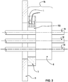
Figure 2 shows the sensor after integration in the anchorage, -
Figure 3 shows the sensor after integration in an encasing tube, -
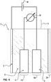
Figure 4 shows the measuring setup for the passivation measurement, -
Figure 5 shows a measurement example of a passivation measurement for different mixture materials, -
Figure 6 shows a measurement example of a passivation measurement for different pH values over time T, -
Figure 7 shows an example of a passivation measurement for different chloride contents of the mixture over time T, -
Figure 8 shows measurement data ofFigure 6 andFigure 7 over time T. - Referring to the drawings (
Figure 3 ), one sees atendon 100 used for the construction of prestressed, suspended and stayed structures (these structures are not represented), such as suspension bridges, cable-stayed bridges, stadium roofs, buildings, telecommunications towers, post-tensioned bridges, containment structures, etc. - The
tendon 100 comprises a plurality ofstrands 10 embedded in a medium made up of a material capable of hardening, e.g. amixture 11 containing at least two components such as cement and water. Thismixture 11 is known by the term grout. Eachtendon 100 comprises a plurality ofstrands 10 which are made up of steel. - The
tendon 100 also comprises a tube, said encasingtube 12, in which thestrands 10 of thetendon 100 are introduced before themixture 11 is poured in the encasingtube 12 in such a manner as to completely fill ahollow space 110 situated between the individual strands and/or between the strands and the encasingtube 12. The encasingtube 12 has a wall which can act as a mould, and which can be considered as constituting a vessel. - The filling mixture namely ensures that the strands are in contact along their entire length with the alkaline pore solution of the
mixture 11. - The invention relates to a method for determining the passivating properties of the
mixture 11. This method for determining the passivating properties of amixture 11 containing at least two components, which are cement and water, includes the steps of: - taking three elements, each made up of an electrically conductive material, these elements being referred to as
first electrode 2,second electrode 4 andthird electrode 5, - fixing at least one of these three electrodes on a
support 3 in such a manner that- they are electrically insulated reciprocally, and
- the
mixture 11 is able to come into contact with at least one predetermined face situated on each electrode, these faces being referred to asfirst face 20,second face 40 andthird face 50,
- selecting the
first electrode 2 and thethird electrode 5 and applying between these two electrodes- a direct current, referred to as first direct current, of predetermined polarity, referred to as first polarity, resulting in electrolytic reactions on the
third electrode 5, for a predetermined duration D1, referred to as first duration D1, and then
- a direct current, referred to as first direct current, of predetermined polarity, referred to as first polarity, resulting in electrolytic reactions on the
- selecting the
second electrode 4 and thethird electrode 5, and- measuring the voltage V between these two electrodes during said first predetermined duration D1, and
- storing the measurement for the variation of said voltage V during said first predetermined duration D1,
- comparing the variations in the voltage V between the
second electrode 4 and thethird electrode 5 during the first predetermined duration D1, with predetermined data defining at least whether or not amixture 11 has passivating properties, and - determining at least whether or not the
mixture 11 has such passivating properties. - The electrolytic reactions on the
third electrode 5 are anodic reactions. - There is also described a
sensor 1 designed to implement the invention. Thissensor 1 has three elements, each made up of an electrically conductive material, these elements being saidfirst electrode 2,second electrode 4 andthird electrode 5, and at least one of these three elements is fixed on asupport 3 in such a manner that these elements are electrically insulated reciprocally. - Using an electrically insulating material as a
support 3, asecond electrode 4, made up of an electrically conductive material, and athird electrode 5, made of steel, are installed in an electrically conducting first
electrode 2, made up of a tubular part. Thefirst electrode 2, thesecond electrode 4 and thethird electrode 5 are electrically connected by means of amulti-core cable 6. - The
first electrode 2 and thesecond electrode 4 are composed ideally of stainless steel. Used as electrically insulating material is e.g. polytetrafluoroethylene, polyethylene or epoxy resin. - As shown in
Figure 2 , thesensor 1 can be integrated in an anchoring device 16 (anchorage). As represented, clamped between a bearing plate 9 and ananchor head 8 is aforce distribution ring 7. Thesensor 1 is integrated in thisforce distribution ring 7. Ideally, thesensor 1 is installed by means of a screw into saidforce distribution ring 7. Theforce distribution ring 7 has a large aperture in which the strands are spaced, and these strands have to be embedded with amixture 11. - The
force distribution ring 7 has a wall which can be considered as constituting a vessel in which themixture 11 can be pored in order to completely fill a hollow space situated between the strands and thedistribution ring 7. - As shown in
Figure 3 , thesensor 1 can be mounted in an encasingtube 12 at a place where aventilation tube 14 is fixed, in such a manner that themixture 11 comes into contact with saidsensor 1. Preferably, thesensor 1 is integrated in theventilation tube 14 in such a manner that it does not stop the exit of air. Alternatively, the sensor may be installed into a similar tube which however, is not used for ventilation. - The steps of comparing the variations in the voltage V between the
second electrode 4 and thethird electrode 5 during the first predetermined duration D1, with predetermined data defining at least whether or not amixture 11 has passivating properties, and determining at least whether or not themixture 11 has such passivating properties, comprises at least: - a) checking whether the difference, said first voltage difference V1, between the maximum voltage value of the first predetermined duration D1 and the voltage value at a first predetermined instant T1 of the first predetermined duration D1, exceeds a first predetermined voltage value or not.
- Preferably :
- before said first direct current of first predetermined polarity, is applied between the
first electrode 2 and thethird electrode 5, for a first period of first predetermined duration D1,- another direct current, referred to as second direct current, of predetermined polarity, referred to as second polarity, opposed to the first polarity, is applied between the
first electrode 2 and thethird electrode 5, for a predetermined duration D2, referred to as second duration D2,
- another direct current, referred to as second direct current, of predetermined polarity, referred to as second polarity, opposed to the first polarity, is applied between the
- when the voltage V between the
second electrode 4 and thethird electrode 5 has been measured during said first predetermined duration D1,- the voltage V between the
second electrode 4 and thethird electrode 5 is measured during said second predetermined duration D2 and then these voltage values are stored,
- the voltage V between the
- when comparing the variations in the voltage V between the
second electrode 4 and thethird electrode 5 during the first predetermined duration D1, with predetermined data defining at least whether or not a mixture has passivating properties, and determining at least whether or not themixture 11 has such passivating properties,- also comparing the variations in the voltage V between the
second electrode 4 and thethird electrode 5 during said second predetermined duration D2.
- also comparing the variations in the voltage V between the
- In this case, the step of selecting the
first electrode 2 and thethird electrode 5 and applying a first direct current and then a second direct current between these two electrodes involves the use of a first direct current and a second direct current with : - a first predetermined polarity and a second predetermined polarity that are opposite,
- a first duration D1 and a second duration D2 that are equal.
- In a preferable manner:
- the first predetermined duration D1 is often seconds (10s), and/or
- the second predetermined duration D2 is often seconds (10s).
- Anodic polarization states occur during the first predetermined duration D1, and cathodic polarization states during the second predetermined duration D2.
- Preferably, the steps of comparing the variations in the voltage V between the
second electrode 4 and thethird electrode 5 during the first predetermined duration D1 and the second predetermined duration D2, with predetermined data defining at least whether or not amixture 11 has passivating properties, and determining at least whether or not themixture 11 has such passivating properties, comprises: - a) checking whether the difference, referred to as first voltage difference V1, between the maximum voltage value of the first predetermined duration D1 and the voltage value at a predetermined instant T1, referred to as first instant T1, of the first predetermined duration D1, exceeds a first predetermined voltage value, or not, and
- b) checking whether the difference, referred to as second voltage difference V2, between the maximum voltage value of the first predetermined duration D1 and the voltage value at a predetermined instant T2, referred to as second instant T2, of the second predetermined duration D2, is within a first predetermined range, or not, and
- c) checking whether the difference, referred to as third voltage difference V3, between the voltage value at a predetermined instant T3, referred to as third instant T3, of the first predetermined duration D1 and the voltage V at a predetermined instant T4, referred to as fourth instant, of the second predetermined duration D2 is within a second predetermined range, or not.
- Preferably at least one of these two conditions is satisfied :
- at least one of the first predetermined instant T1 and the fourth predetermined instant T4 is between ten percent and one hundred percent of the value of the first predetermined duration D1, and
- at least one of the second predetermined instant T2 and the third predetermined instant T3 is between ten percent and one hundred percent of the value of the second predetermined duration D2.
- The value of the first predetermined duration D1 is between one second and thirty seconds, and/or the value of the second predetermined duration D2 is between one second and thirty seconds.
- Preferably at least one of these two conditions is satisfied :
- at least one of the first predetermined instant T1 and the fourth predetermined instant T4 is equal to ninety percent of the value of the first predetermined duration D1, and
- at least one of the second predetermined instant T2 and the third predetermined instant T3 is equal to ninety percent of the value of the second predetermined duration D2.
- According to the invention, for the step of selecting the
first electrode 2 and thethird electrode 5 and applying between these two electrodes - a first direct current of first predetermined polarity, for a first predetermined duration D1, and then
- a second direct current of second polarity opposed to the first polarity, for a second predetermined duration D2 :
- the first direct current is such that a density of current of two point five milliampere per square centimeter (2.5 mA/cm2) emerges from the
third electrode 5, and - the second direct current is such that a density of current of two point five milliampere per square centimeter (2.5 mA/cm2) emerges from the
first electrode 2.
- the first direct current is such that a density of current of two point five milliampere per square centimeter (2.5 mA/cm2) emerges from the
- Preferably, for the step of comparing the variations in the voltage V between the
second electrode 4 and thethird electrode 5 with predetermined data defining at least whether or not a mixture has passivating properties, when: - the first voltage difference V1 is a maximum of fifty millivolts (50 mV) (first predetermined voltage value),
- the second voltage difference V2 is one point eight volts to two point three volts (1.8 V to 2.3 V) (first predetermined range), and
- the third voltage difference V3 is one point eight volts to two point three volts (1.8 V to 2.3 V) (second predetermined range),
- It is easy to understand that the method of the invention also indirectly allows checking the filling of an encasing tube with the aforementioned mixture, at least in the vicinity of the three electrodes.
- In the step of comparing the variations in the voltage V between the
second electrode 4 and thethird electrode 5 with predetermined data defining at least whether or not amixture 11 has passivating properties, when the change in potential between - the fourth second of at least the first predetermined duration D1 and second D2 predetermined duration, and
- the ninth second of at least the first predetermined duration D1 and second D2 predetermined duration is more than six millivolts (6 mV),
- Preferably, the step consisting of taking three elements, each made up of an electrically conductive material, these elements being said
first electrode 2,second electrode 4 andthird electrode 5, each of these three electrodes having at least oneface - Shown in
Figure 4 is a measuring setup for the passivation measurement. By means of apower source 18, such as e.g. a battery or a galvanostat, a current is impressed between thefirst electrode 2 and thethird electrode 5. With avoltage measuring device 19, such as e.g. a voltmeter, the voltage V is measured between thethird electrode 5 and thesecond electrode 4. - The result of this measurement for various media in contact with the
sensor 1 is represented inFigure. 5 . Shown on the horizontal axis is the voltage V (volts) between thesecond electrode 4 and thethird electrode 5, and shown on the vertical axis is the current density CD emerging from the third electrode 5 (mA/cm2). - For a filling of the hollow space 120 with a
mixture 11 of a passivating chloride-free alkaline type (curve "e"), a maximal voltage is achieved through the current flow, which maximal voltage is limited by the development of oxygen. The increase in thethird electrode 5 compared with thesecond electrode 4, in this case composed of stainless steel, to a value higher than 0.5 volt indicates efficient passivation. - If the hollow space 120 is filled with diluted bleed water (curve "f"), the measurable voltage V increase under flow of current is significantly lower. The value of 0.5 volt is not surpassed. This indicates the triggering of corrosion owing to too low an alkalinity.
- In the case of a filling of the hollow space 120 with tap water, a very negative voltage V is even measured (curve "g"). This indicates extensive corrosion of the steel of the strands.
- The procedure shown in
Figure 5 exhibits the disadvantage that the measurement of the potential of thethird electrode 5 to thestainless steel electrode 4 is influenced by the oxygen content in themixture 11 and the passivation quality of thesecond electrode 4. - Moreover, the presence of a passive film on the
third electrode 5 from a previous exposure to a passivating environment may result in misleading results indicating passivity even in an aggressive environment. - These problems are overcome by the above-mentioned method, as shown in
Figure 6 for different pH values. - As mentioned in the foregoing, the passive film possibly formed on the
third surface 50 ofthird electrode 5 is removed by cathodic polarization (second direct current of second polarity, for a second predetermined duration D2 = e.g. 10 seconds by a current of -2.5 mA/cm2). The current is impressed between thefirst electrode 2 and thethird electrode 5. - A new passive film develops on the
third surface 50 of thethird electrode 5 through the application of an anodic current between thethird electrode 5 and the first electrode 2 (first direct current of first predetermined polarity opposed to the second polarity for a first predetermined duration D1 = e.g. 10 seconds by a current of +2.5 mA/cm2). - During the measurement, the alkalinity changes owing to the hydrogen and oxygen development taking place on the
third surface 50 ofthird electrode 5. This effect can be minimized if the amount of charge during the cathodic and anodic polarization is equal. - This is the case if the cathodic polarization lasts for ten seconds at minus two point five mA/cm2 (-2.5 mA/cm2) and the anodic polarization lasts for 10 seconds at plus two point five mA/cm2 (+2.5 mA/cm2). As a consequence, repeated measurements result in minimal interference with the pH of the
mixture 11. - Shown in
Figure 6 are the electrochemical processes taking place on thethird surface 50 ofthird electrode 5. Starting with an undefinedthird surface 50 with possible oxide and passive film coverage, a cathodic polarization (first curve part CP1) reduces all residual protective passive film. - A subsequent anodic polarization will result in the formation of a protective passive film if the pH value is sufficiently high and the chloride content sufficiently low (second curve part CP2). This is the case for pH values equal to twelve or higher than twelve (
pH 12, pH 13). - If the pH value of the
mixture 11 is too low (e.g. pH 11) or the chloride content too high, formation of a passive film may take place (third curve part CP3); however, the subsequent polarization can cause the partial failure of the passive film resulting in corrosion activation and a drop in potential (fourth curve part CP4). - If the pH value of the
mixture 11 is very low (e.g. pH 7), no formation of a passive film will take place at all (fifth curve part CP5). - The decision about the activation of corrosion is possible based on the potential difference between the
second electrode 4 and thethird electrode 5. Although thesecond electrode 4 is not a stable reference electrode with a well defined potential value, the passivation measurement is very reliable. This is owing to the fact that the decision about the activation of corrosion is possible based on a potential decrease during the anodic polarization between third curve part CP3 and fourth curve part CP4 and/or based on the difference between first curve part CP1 and fifth curve part CP5. - Since the decision about the activation of corrosion is based on the difference between two potential readings, the possible error in relation to the
second electrode 4 is eliminated. - The procedure shown in
Figure 6 uses in addition hydrogen development during a cathodic polarization (first curve part CP1) and/or oxygen development during anodic polarization (second curve part CP2) to determine the effect of the potential of thesecond electrode 4 and to estimate the effect of the ohmic potential drop in themixture 11. - Since the potential difference between the oxygen and hydrogen development in
alkaline mixture 11 is roughly around two volts, the difference between these two potentials can be used as a criterion for evaluating the wetting of thethird electrode 5 with amixture 11 having passivating properties. - Based on the examples shown, the following criteria can be used to determine the presence of a
passivating mixture 11 on the surface of the sensor 1: - a) The difference between the maximum potential during an anodic polarization (second curve part CP2, third curve part CP3, fifth curve part CP5) and the potential after a defined time during anodic polarization (second curve part CP2, fourth curve part CP4, fifth curve part CP5) (T1 : e.g. 9 seconds) may not exceed a certain value (e.g. 50 mV),
- b) The difference between the maximum potential in anodic polarization (second curve part CP2, third curve part CP3, fifth curve part CP5) and the potential after a defined time during cathodic polarization (first curve part CP1) (T2 : e.g. nine seconds) must be within a certain range (e.g. one point eight and two point three volts),
- c) The difference between the potential after a defined time during anodic polarization (second curve part CP2, third curve part CP3, fifth curve part CP5) (T3 : e.g. nine seconds) and the potential after a defined time during cathodic polarization (first curve part CP1) (T4 : e.g. nine seconds) must be within a certain range (e.g. one point eight and two point three volts).
- The above-mentioned conditions "a", "b" and "c" make it possible to eliminate the effect of possible potential fluctuations of the
second electrode 4. - Moreover they take into account the ohmic potential drop in the
mixture 11, which can influence the measurement as well. Investigating various parameters, it was shown that a most reliable determination of the wetting of thesensor 1 withmixture 11 having passivating properties can be achieved through a combination of the conditions "a" and "b". However, also condition "c" or "a" alone allows determination of the wetting of the surfaces of the sensor with amixture 11 having passivating properties. - In
Figure 7 , the corresponding measurement is shown for atypical mixture 11 with different chloride contents. The difference between the maximum potential and the potential after nine seconds in anodic polarization is zero for zero point one and zero point two % CI- (chloride), demonstrating the passivating properties of themixture 11. - In contrast, this difference is about seven hundred and fifty mV for zero point four % CI- (chloride), demonstrating the activation of corrosion.
- The determination of the difference between the maximum potential in anodic polarization and the potential after a defined time during cathodic polarization (first curve part CP1) (e.g. nine seconds) allows determination of the ohmic potential drop in the
mixture 11. - Since the ohmic potential drop will increase, once the
mixture 11 starts to set, monitoring of the potential drop over time can be used to determine whether thesensor 1 is in contact with a hardeningmixture 11 having passivating properties or only with bleed water having passivating properties. - This procedure requires the measurement of the ohmic potential drop in the
mixture 11 after at least twenty-four hours after the injection of themixture 11 in the encasingtube 12. - If the reading indicates the presence of bleed water, the problem can no longer be corrected. Therefore it would be most helpful if the decision about the presence of bleed water could be made based on a measurement taken directly after injection of the
mixture 11, when it is still possible to correct the situation through additional injection. - The invention makes such a decision possible using the electrochemical processes involved. During cathodic polarization not only are residual oxide layers removed, but also hydrogen development takes place and the pH value of the
mixture 11 increases. - On the other hand, the anodic polarization will not only result in the formation of a passive film, but also in oxygen development and decrease in the pH value of the
mixture 11. The potential for oxygen and hydrogen development are dependent on the pH value according to the Nernst equation. - As a consequence, the potential will change with increasing polarization time, during both the anodic and cathodic polarization. Since the rate of pH change is defined by the applied current density CD, the potential change should always be identical for all tests.
- The pH change, however, is not only influenced by the amount of hydroxide or hydrogen ions produced, but also by their accumulation on the front of the
third electrode 5. As a consequence, the pH value will change fast if amixture 11 with passivating properties is present in contact with thethird electrode 5. - If, on the other hand, bleed water is in contact with the
third electrode 5, the convection and the high diffusion rate in the liquid will prevent the accumulation of the hydroxide or hydrogen ions. As a consequence, the change in pH value will be smaller, and the change in potential will be smaller too. The monitoring of the potential over time allows, therefore, determining the accumulation of reaction products (hydrogen or hydroxide ions) in contact with thethird electrode 5. - This effect is illustrated in
Figure 8 , where the results ofFigure 5 , pH thirteen (pH 13), andFigure 7 , zero % CI- (chloride), are compared. While the potential remains more or less constant in the electrolyte with pH thirteen (pH 13) after the maximum value is reached, a continuous increase is observed for themixture 11 with zero % CI- (chloride). - Under the given measurement conditions, the increase in potential during second fourteen and twenty of the anodic polarization should be at least six mV if
mixture 11 with passivating properties is present in contact with thethird electrode 5. This effect will increase with the hardening of themixture 11, since the transport of the reaction products (hydroxide ions during cathodic polarization and hydrogen ions during the anodic polarization) gets slower in the solid mixture. - This very same effect can be used in later investigations for determination of the pH value on the
third electrode 5. During anodic polarization, the alkalinity of themixture 11 in contact with thethird electrode 5 will decrease with ongoing polarization. At a constant anodic polarization current, the change in pH will occur more quickly when the starting pH value was lower, since fewer neutralizing hydroxide ions were available. Hence the potential drop over time will be greater in a low pH value environment. If the pH value in themixture 11 is high, the same current over time creates a smaller change in pH value, and a smaller change in potential is measured. - This procedure allows determining the pH value in front of the
third electrode 5, provided that the diffusion rate for the produced hydrogen ions and the neutralizing hydroxide ions in themixture 11 is constant over time, or known. If the current is applied in a way that the overall charge is zero after the entire test, the pH changes introduced can be compensated. - In the example shown, the decision about the passivating properties of the
mixture 11 was based on a ten-second anodic polarization. Alternatively, it is possible instead to continue the anodic polarization until corrosion activation takes place and a decrease in potential is observed. This effect will occur since the pH value will decrease over time owing to the production of hydrogen ions in anodic polarization. Therefore, the ratio between chloride ions and hydroxide ions will decrease over time, and activation will take place. This procedure allows getting quantitative information about the passivating properties of themixture 11 instead of just pass/fail information. A more detailed analysis of the chloride content is possible, based on this procedure. - Use of the
sensor 1 thus makes possible a comprehensive guarantee of the corrosion protection of tendons. Thesensor 1 can be simply integrated at all critical areas in the anchorage and in the encasingtube 12, and, by means of a simple passivation measurement, enables checking the filling during the step of injection with the corrosion-protection mixture 11. - In the event of flaws or errors, steps can thus be directly taken during the injection, and the
mixture 11 can be replaced again. In contrast to alternative methods, such as monitoring through radar or visual inspection, the filling of the encasingtube 12 is checked directly during the injection. Above and beyond this, possible for the first time is a direct monitoring of the corrosion protection effect of themixture 11, using thesensor 1. This measurement is so quick and uncomplicated that it can be done upon completion of the injection. Thus it is possible to take steps, if necessary, before the setting of themixture 11. - Different variants of the procedure are conceivable. For example, each
sensor 1 can be equipped with a measuring device that continuously measures the passivating properties and sends the data to a central station at the injection pump. The personnel can thereby follow the position of the front end of themixture 11 in the encasingtube 12 during the injection. - In addition, there exists the possibility of transmitting these data via a wireless network to an independent station which carries out the logging of the complete injection operation for the builder.
- The passivation measurement shown can also be carried out by hand using a simple battery and a voltmeter. A simple current pulse of predetermined duration can thereby be used.
- This can take place through interruption of the current. Using this simple battery-driven device, the measurement can also be carried out at the same time based on current and voltage V. Measurement of the grouting mixture and of the corrosion protective effect is thereby possible in one operation.
- Furthermore there exists the possibility of running the electrical connections of all
sensors 1 or of selectedsensors 1 into a central measuring box, and using them for later monitoring measurements. The design also permits application of other methods such as impedance spectroscopy, galvanostatic pulse measurement, determination of the linear polarization resistance and potential and corrosion current measurement. - Moreover in the case of a connection to the tendon, as exists in the situation in
Figure 2 , for example, measurements directly on thetendon 10 are possible. Thesensor 1 thus enables not only comprehensive and direct quality control during the injection operation, it also offers the possibility of long-term corrosion monitoring of thetendon 10. - The
sensors 1 can thereby be integrated directly into a comprehensive monitoring system of the structure. The voltage V between thesecond electrode 4 and thethird electrode 5 can thus be captured as a function of time. With the onset of corrosion, the voltage V will decrease. Alternatively, the current between thethird electrode 5 and thering 2 can be measured as a function of time. With an increase in the current, conclusions can likewise be drawn regarding corrosion onset and even rate of corrosion. Moreover, the voltage between thestrands 10 and thesecond electrode 4 can be measured. - Additionally, the
sensor 1 may be used to judge the effect of the cathodic protection on the potential distribution on the tendon. The polarization of thestrand 10 can be determined by measuring the potential between thesecond electrode 4 and thestrand 10. Simultaneously the cathodic current density on thethird electrode 5 can be determined allowing estimation of the level of cathodic protection. This possibility is especially relevant for electrically insulated tendons. - The invention is of course not limited to the embodiment example shown and described. Thus the
sensor 1 can contain further electrodes, so that the passivation measurement can run on independent electrodes. - Instead of the
first electrode 2, any otherthird electrode 5 in thesensor 1 can be used. It is also possible to use a contact in the reinforcement of the concrete structure instead of thefirst electrode 2 orsecond electrode 4. This is possible, since the reinforcement is typically in contact with the bearing plate, the anchor head and the strands. Additionally it is possible to combinefirst electrode 2 andsecond electrode 4 in one electrode. This is especially possible if the surface of the combined electrode is large. Therefore the reinforcement or the strands or the anchor head would be suitable as a combined electrode for this application. - The material of the
second electrode 4, thethird electrode 5 and thefirst electrode 2 has to show electrical conductivity. Thus copper, graphite, carbon-fiber-reinforced plastic, a plastic filled with any electrically conductive material, or any other metal can be used instead of stainless steel, for example. For the passivation measurement, it is essential that thethird electrode 5 be composed of an iron-based material having as similar as possible a passivation behavior as the strands. Use of steel or use of steel prestressing strands is obvious. Using iron is also conceivable, however. - If the detection of the presence of
mixture 11 with passivating properties instead of bleed water or the determination of the pH value at later stages is the only information of interest, the material ofthird electrode 5 can be of any electrically conductive material. For anodic polarization, it is preferably an inert or passive material, such as gold, platinum, graphite titanium, tantalum, etc. There are no limitations regarding the geometry of the electrode. It can have any shape as shown inFigure 1 . It is important to note that it does not have to exhibit a planar shape. - For example, a cylindrical geometry may also be used. Additionally it is possible to segment the
third electrode 5 into several single electrodes which are located in the same area or which are spread out. For example it is possible to introduce several individualthird electrodes 5 in the sameforce distribution ring 7. In one single measurement, several areas would be tested. It is even possible to extend thethird electrode 5 over theentire encasing tube 12. This electrode could be split in single individual electrodes. This could be achieved by using a wire that is insulated and that is introduced parallel to the prestressing strands. By removing the insulation in the critical areas or at regular intervals, the information about the filling of theentire encasing tube 12 withmixture 11 with passivating properties could be obtained in a single measurement. For example, a prestressing strand coated with polyethylene could be used. Wherever the presence ofmixture 11 has to be confirmed, the polyethylene has to be removed prior to insertion into the encasingtube 12. - The use of a constant current results in easy interpretation of the results.
- Since the
second electrode 4 is not carrying any current, its conductivity is not critical. Its only function is to exhibit a stable potential during the time of the measurement. As a consequence, not only the materials listed for thethird electrode 5, but also organic and inorganic semiconductors, or even polymer-coated metals and semiconductors may be used. - There exists furthermore the possibility of integrating a reference electrode into the
sensor 1 in order to be able to measure the absolute electrochemical potential. In this case, the voltage V measurement would take place between the reference electrode and thethird electrode 5. Exact determination of the pH value of themixture 11 would thereby be feasible. - The invention can also be applied to the monitoring of the passivation properties and pH value of other concretes or
mixtures 11 used in concrete structures. - The change in potential in the solid mixture can be used to determine the alkalinity of the
mixture 11 at any later point in time. - The measuring of the potential polarization resistance of the
second electrode 4 can be used for monitoring of the corrosion behavior over time.
Claims (13)
- A method for determining the passivating properties of a mixture (11) containing at least two components, which are cement and water, including the steps of:- taking a sensor comprising three elements, each made up of an electrically conductive material, these elements being referred to as first electrode (2), second electrode (4) and third electrode (5),- fixing at least one of these three electrodes on a support (3) in such a manner that• they are electrically insulated reciprocally, and• the mixture (11) is able to come in contact with at least one predetermined face situated on the first electrode (2), second electrode (4) and third electrode (5), these faces being referred to as first face (20), second face (40) and third face (50), respectively,- selecting the first electrode (2) and the third electrode (5) and applying between these two electrodes,• a direct current, referred to as first direct current, of predetermined intensity value, referred to as first intensity value, and predetermined polarity, referred to as first polarity, resulting in electrolytic reactions on the third electrode (5), for a predetermined duration (D1), referred to as first duration, and then- selecting the second electrode (4) and the third electrode (5), and• measuring the voltage (V) between these two electrodes during said first predetermined duration (D1), and• storing the measurement for the variation of said voltage (V) during said first predetermined duration (D1),- comparing the variations in the voltage (V) between the second electrode (4) and the third electrode (5) during the first predetermined duration (D1), with predetermined data representing the variations in said voltage (V) during said first predetermined duration (D1) for different pH values of the mixture, and- determining, based on the comparison, at least whether or not the mixture (11) has such passivating properties.
- The method according to claim 1, characterized in that the steps of comparing the variations in the voltage (V) between the second electrode (4) and the third electrode (5) during the first predetermined duration (D1), with predetermined data defining at least whether or not a mixture (11) has passivating properties, and determining at least whether or not the mixture (11) has such passivating properties, consists at least in:
checking whether the difference, referred to as first voltage difference (V1), between the maximum voltage value of the first predetermined duration (D1) and the voltage value at a first predetermined instant (T1) of the first predetermined duration (D1), exceeds a first predetermined voltage value or not. - The method according to claim 1, characterized in that it further comprises the steps of:- before said first direct current of first predetermined polarity is applied between the first electrode (2) and the third electrode (5), for a first period of first predetermined duration (D1),• applying another direct current, referred to as second direct current, of predetermined value, referred to as second value, and predetermined polarity, referred to as second polarity, opposed to the first polarity, between the first electrode (2) and the third electrode (5), for a predetermined duration (D2), referred to as second duration (D2);• measuring the voltage (V) between the second electrode (4) and the third electrode (5) during said second predetermined duration (D2), and then storing these voltage values;• also comparing the variations in the voltage (V) between the second electrode (4) and the third electrode (5) during said second predetermined duration (D2), with predetermined data defining at least whether or not a mixture (11) has passivating properties.
- The method according to claim 3, characterized in that the step of selecting the first electrode (2) and the third electrode (5) and applying a first direct current and then a second direct current between these two electrodes involves the use of a first direct current and a second direct current with:- a first predetermined polarity and a second predetermined polarity that are opposite, and- a first duration (D1) and a second duration (D2) that are equal.
- The method according to claim 4, characterized in that the steps of comparing the variations in the voltage (V) between the second electrode (4) and the third electrode (5) during the first predetermined duration (D1) and the second predetermined duration (D2), with predetermined data defining at least whether or not a mixture (11) has passivating properties, and determining at least whether or not the mixture (11) has such passivating properties, comprises:- a) checking whether the difference, referred to as first voltage difference (V1), between the maximum voltage value of the first predetermined duration (D1) and the voltage value at a predetermined instant (T1), referred to as first predetermined instant (T1), of the first predetermined duration (D1), exceeds a first predetermined voltage value, or not, and/or- b) checking whether the difference, referred to as second voltage difference (V2), between the maximum voltage value of the first predetermined duration (D1) and the voltage value at a predetermined instant (T2), referred to as second predetermined instant, of the second predetermined duration (D2), is within a first predetermined range, or not, and/or- c) checking whether the difference, referred to as third voltage difference (V3), between the voltage value at a predetermined instant (T3), referred to as third predetermined instant (T3), of the first predetermined duration (D1) and the voltage (V) at a predetermined instant (T4), referred to as fourth predetermined instant (T4), of the second predetermined duration (D2) is within a second predetermined range, or not.
- The method according to claim 5, characterized in that at least one of these two conditions is satisfied:- at least one of a period starting from the same time instant as the first predetermined duration (D1) starts and ending at the first predetermined instant (T1) and a period starting from the same time instant as the first predetermined duration (D1) starts and ending at the fourth predetermined instant (T4) is between ten percent and one hundred percent of the value of the first predetermined duration (D1), and- at least one of a period starting from the same time instant as the first predetermined duration (D1) starts and ending at the second predetermined instant (T2) and a period starting from the same time instant as the first predetermined duration (D1) starts and ending at the third predetermined instant (T3) is between ten percent and one hundred percent of the value of the second predetermined duration (D2).
- The method according to one of the claims 5 to 6, characterized in that at least one of these two conditions is satisfied:- at least one of a period starting from the same time instant as the first predetermined duration (D1) starts and ending at the first predetermined instant (T1) and a period starting from the same time instant as the first predetermined duration (D1) starts and ending at the fourth predetermined instant (T4) is equal to ninety percent of the value of the first predetermined duration (D1), and- at least one of a period starting from the same time instant as the first predetermined duration (D1) starts and ending at the second predetermined instant (T2) and a period starting from the same time instant as the first predetermined duration (D1) starts and ending at the third predetermined instant (T3) is equal to ninety percent of the value of the second predetermined duration (D2).
- The method according to one of the claims 3 to 7, characterized in that the value of at least one of the first predetermined duration (D1) and the second predetermined duration (D2) is between one second and thirty seconds.
- The method according to one of the claims 3 to 8, characterized in that at least one of the first predetermined duration (D1) and the second predetermined duration (D2) is of ten seconds (10s).
- The method according to one of the claims 3 to 9, characterized in that for the step of selecting the first electrode (2) and the third electrode (5) and applying between these two electrodes• a first direct current of first predetermined polarity, for a first predetermined duration (D1), and then• a second direct current of second polarity opposed to the first polarity, for a second predetermined duration (D2):- the first direct current is such that a density of current of two point five milliampere per square centimeter (2.5 mA/cm2) emerges from the third electrode (5), and- the second direct current is such that a density of current of two point five milliampere per square centimeter (2.5 mA/cm2) emerges from the first electrode (2).
- The method according to one of the claims 5 to 7, characterized in that for the step of comparing the variations in the voltage (V) between the second electrode (4) and the third electrode (5) with predetermined data defining at least whether or not a mixture has passivating properties, when:- the first voltage difference (V1) is a maximum of fifty millivolts,- the second voltage difference (V2) is one point eight volts to two point three volts, and- the third voltage difference V3 is one point eight volts to two point three volts,the conclusion is that the mixture (11) has passivating properties, at least in the vicinity of the third electrode (5).
- The method according to one of the claims 5 to 10, characterized in that in the step of comparing the variations in the voltage (V) between the second electrode (4) and the third electrode (5) with predetermined data defining at least whether or not a mixture (11) has passivating properties, when a change in potential between• the fourth second of at least one of the first (D1) and second (D2) predetermined duration, and• the ninth second of at least one of the first (D1) and second (D2) predetermined duration is more than six millivolts (6 mV),the conclusion is that the third electrode (5) is in contact with a mixture (11) made up of hardening cement and water, instead of only bleed water, that is to say liquid emerging from a mixture (11) of water and cement.
- The method according to one of the claims 1 to 12, characterized in that the step consisting of taking three elements, each made up of an electrically conductive material, these elements being said first electrode (2), second electrode (4) and third electrode (5), each of these three electrodes having at least one face (20, 40, 50), comprises the operation of selecting three elements each made up of steel.
Applications Claiming Priority (1)
| Application Number | Priority Date | Filing Date | Title |
|---|---|---|---|
| PCT/EP2006/066241 WO2008031453A1 (en) | 2006-09-11 | 2006-09-11 | Method and sensor for determining the passivating properties of a mixture containing at least two components, which are cement and water |
Publications (2)
| Publication Number | Publication Date |
|---|---|
| EP2062038A1 EP2062038A1 (en) | 2009-05-27 |
| EP2062038B1 true EP2062038B1 (en) | 2019-09-25 |
Family
ID=37909493
Family Applications (1)
| Application Number | Title | Priority Date | Filing Date |
|---|---|---|---|
| EP06793420.8A Active EP2062038B1 (en) | 2006-09-11 | 2006-09-11 | Method and sensor for determining the passivating properties of a mixture containing at least two components, which are cement and water |
Country Status (8)
| Country | Link |
|---|---|
| US (1) | US8278949B2 (en) |
| EP (1) | EP2062038B1 (en) |
| JP (1) | JP5097776B2 (en) |
| KR (1) | KR101286165B1 (en) |
| CN (1) | CN101517405B (en) |
| AU (1) | AU2006348127B2 (en) |
| TW (1) | TWI445952B (en) |
| WO (1) | WO2008031453A1 (en) |
Families Citing this family (16)
| Publication number | Priority date | Publication date | Assignee | Title |
|---|---|---|---|---|
| US9109991B2 (en) * | 2013-04-30 | 2015-08-18 | Lietai Yang | Electrochemical probe with coated, fingered electrodes for corrosion monitoring in oil-water mixtures and gas systems containing hydrogen sulfide |
| RU2533344C1 (en) * | 2013-07-09 | 2014-11-20 | Федеральное государственное бюджетное образовательное учреждение высшего профессионального образования "Пензенский государственный университет" (ФГБОУ ВПО "Пензенский государственный университет") | Installation for electrochemical survey of metal corrosion |
| US9829452B2 (en) | 2013-10-08 | 2017-11-28 | University Of Florida Research Foundation, Inc. | Corrosion detection in structural tendons |
| MX358579B (en) | 2013-10-31 | 2018-08-27 | Halliburton Energy Services Inc | Correlating energy to mix cement slurry under different mixing conditions. |
| US10161893B2 (en) | 2014-08-19 | 2018-12-25 | Transtech Systems, Inc. | Characterization of material under test (MUT) with electromagnetic impedance spectroscopy |
| US10527570B2 (en) | 2016-01-12 | 2020-01-07 | Transtech Systems, Inc. | Determining location of electromagnetic impedance spectrographic analysis using electromagnetic impedance tomography |
| DE102017209300A1 (en) * | 2017-06-01 | 2018-12-06 | Robert Bosch Gmbh | Method for determining a state of at least one component of a sensor for detecting at least one property of a measurement gas in a measurement gas space |
| DE102017219449B4 (en) | 2017-10-30 | 2026-01-22 | Robert Bosch Gmbh | extraction attachment |
| JP2019158377A (en) * | 2018-03-07 | 2019-09-19 | 株式会社シュリンクス | Measurement method of corrosion rate using acm sensor |
| RU2695961C1 (en) * | 2018-09-26 | 2019-07-29 | Анна Владимировна Родькина | Complex for investigation of electrochemical characteristics of ship hull structures and floating technical structures |
| CN109827898B (en) * | 2019-03-29 | 2021-09-17 | 河海大学 | Metal corrosion test device |
| FR3105831B1 (en) | 2019-12-30 | 2021-12-10 | Grtgaz | Device with a pH sensor intended for insertion into the soil, method of measuring pH, in particular for cathodic protection |
| RU2761767C1 (en) * | 2021-04-16 | 2021-12-13 | ФЕДЕРАЛЬНОЕ ГОСУДАРСТВЕННОЕ БЮДЖЕТНОЕ УЧРЕЖДЕНИЕ НАУКИ ИНСТИТУТ ПРОБЛЕМ ЭКОЛОГИИ И ЭВОЛЮЦИИ им. А.Н. СЕВЕРЦОВА РОССИЙСКОЙ АКАДЕМИИ НАУК (ИПЭЭ РАН) | Device for non-destructive electrochemical monitoring of the surface condition of metal samples in electrolyte |
| NL2030136B1 (en) | 2021-12-15 | 2023-06-27 | Isenspro Nv | Device and method for measuring a conduit in a submerged or subterraneous environment |
| PL244098B1 (en) * | 2022-01-31 | 2023-11-27 | Politechnika Slaska Im Wincent | Method of applying a reinforcement corrosion rate sensor, especially in existing reinforced concrete structures |
| DE102024117125A1 (en) * | 2024-06-18 | 2025-12-18 | Endress+Hauser Conducta Gmbh+Co. Kg | Conductive conductivity sensor and method for position control of a conductive conductivity sensor |
Family Cites Families (18)
| Publication number | Priority date | Publication date | Assignee | Title |
|---|---|---|---|---|
| US3788962A (en) | 1971-11-11 | 1974-01-29 | Du Pont | Apparatus for monitoring the corrosion rate of metal by the polarization resistance method |
| DE2335419A1 (en) * | 1973-07-12 | 1975-02-06 | Battelle Institut E V | Measurement of danger of corrosion of concrete reinforcement - involves application of electrode to concrete and connection to steel reinforcement |
| EP0084404B1 (en) * | 1982-01-05 | 1989-05-31 | University Of Manchester Institute Of Science And Technology | Corrosion monitoring |
| JPH0812168B2 (en) * | 1988-04-04 | 1996-02-07 | 株式会社ナカボーテック | A method for measuring the polarization resistance of rebar in concrete. |
| SU1727942A1 (en) | 1990-06-26 | 1992-04-23 | Центральное проектно-конструкторское бюро кузнечно-прессового машиностроения | Device for monitoring load on electric drive of press-forging machine |
| DE4025548C2 (en) * | 1990-08-11 | 1995-06-14 | Heraeus Elektrochemie | Short-circuit detection method during the concreting of a protective electrode serving as an anode for cathodic corrosion protection of reinforced concrete structures and device therefor |
| US5015335A (en) | 1990-09-17 | 1991-05-14 | Champion International Corporation | Chlorine dioxide static distributor |
| IL104837A (en) * | 1992-03-23 | 1996-01-31 | Norwegian Concrete Tech | Method for electrochemical treatment of reinforcing steel in concrete having embedded steel reinforcement |
| EP0573692A1 (en) * | 1992-06-18 | 1993-12-15 | Asanuma Corporation | Concrete sensor |
| US5596460A (en) * | 1994-12-27 | 1997-01-21 | International Business Machines Corporation | System and method for encoding a servo address |
| NO951130L (en) * | 1995-03-24 | 1996-09-25 | Rescon As | Measurement of environmental parameters in concrete |
| JP2929270B2 (en) * | 1995-12-21 | 1999-08-03 | 財団法人日本建築総合試験所 | Method and apparatus for measuring carbonation of concrete |
| EP0867695A3 (en) * | 1997-03-26 | 1999-08-04 | Bilfinger + Berger Bauaktiengesellschaft | Method and device for detecting the degree of filling of formworks with concrete, as well as its compacting, by exploiting its electrical properties |
| CN1195897C (en) * | 1998-10-29 | 2005-04-06 | 福斯洛克国际有限公司 | Connectors for cathodic protection and methods of use |
| JP4082638B2 (en) * | 1999-02-10 | 2008-04-30 | 三井住友建設株式会社 | Grout fillability inspection device and fillability inspection method |
| US6690182B2 (en) * | 2000-07-19 | 2004-02-10 | Virginia Technologies, Inc | Embeddable corrosion monitoring-instrument for steel reinforced structures |
| WO2004010104A2 (en) * | 2002-07-18 | 2004-01-29 | The Johns Hopkins University | Embeddable corrosion rate meters for remotely monitoring structures |
| JP2004239638A (en) * | 2003-02-03 | 2004-08-26 | Mitsubishi Electric Corp | Method and apparatus for determining water corrosivity |
-
2006
- 2006-09-11 EP EP06793420.8A patent/EP2062038B1/en active Active
- 2006-09-11 JP JP2009527019A patent/JP5097776B2/en active Active
- 2006-09-11 KR KR1020097005006A patent/KR101286165B1/en active Active
- 2006-09-11 AU AU2006348127A patent/AU2006348127B2/en active Active
- 2006-09-11 US US12/440,783 patent/US8278949B2/en active Active
- 2006-09-11 CN CN2006800558030A patent/CN101517405B/en active Active
- 2006-09-11 WO PCT/EP2006/066241 patent/WO2008031453A1/en not_active Ceased
-
2007
- 2007-09-07 TW TW096133360A patent/TWI445952B/en active
Non-Patent Citations (1)
| Title |
|---|
| None * |
Also Published As
| Publication number | Publication date |
|---|---|
| WO2008031453A1 (en) | 2008-03-20 |
| TW200819738A (en) | 2008-05-01 |
| AU2006348127B2 (en) | 2012-05-31 |
| CN101517405A (en) | 2009-08-26 |
| KR101286165B1 (en) | 2013-07-15 |
| TWI445952B (en) | 2014-07-21 |
| JP2010502964A (en) | 2010-01-28 |
| KR20090053809A (en) | 2009-05-27 |
| US8278949B2 (en) | 2012-10-02 |
| US20100039125A1 (en) | 2010-02-18 |
| CN101517405B (en) | 2013-02-27 |
| JP5097776B2 (en) | 2012-12-12 |
| HK1133920A1 (en) | 2010-04-09 |
| EP2062038A1 (en) | 2009-05-27 |
| AU2006348127A1 (en) | 2008-03-20 |
Similar Documents
| Publication | Publication Date | Title |
|---|---|---|
| TWI445952B (en) | Method and sensor for determining the passivating properties of a mixture containing at least two components, which are cement and water | |
| Raupach et al. | Macrocell sensor systems for monitoring of the corrosion risk of the reinforcement in concrete structures | |
| Duffó et al. | Development of an embeddable sensor to monitor the corrosion process of new and existing reinforced concrete structures | |
| McCarter et al. | Sensor systems for use in reinforced concrete structures | |
| CN112033885B (en) | A device and method for determining the critical chloride ion concentration of steel bar depassivation in cement-based materials | |
| CN103234897B (en) | A kind of device for monitoring corrosive medium erosion process in concrete | |
| Raupach et al. | Condition survey with embedded sensors regarding reinforcement corrosion | |
| Schiegg et al. | On-line monitoring of corrosion in reinforced concrete structures | |
| Ramón-Zamora et al. | Integrated sensor network for monitoring steel corrosion in concrete structures | |
| CN106442682B (en) | A method for measuring the critical current density of hydrogen evolution of steel bars in reinforced concrete structures | |
| CN212275540U (en) | A device for determining the critical chloride ion concentration of steel bar depassivation in cement-based materials | |
| RU2484448C1 (en) | Method and device to realise contact of electrochemical protection parameters monitoring unit with pipe with applied weighting concrete coating | |
| RU2419090C2 (en) | Method and sensor for determining passivating properties of mixture containing cement and water | |
| CN109856205B (en) | Sensor for monitoring chloride ion concentration of different depths of concrete structure | |
| Vedalakshmi et al. | Embeddable corrosion rate‐measuring sensor for assessing the corrosion risk of steel in concrete structures | |
| HK1133920B (en) | Method and sensor for determining the passivating properties of a mixture containing at least two components, which are cement and water | |
| JP6618212B2 (en) | Desalination treatment system for concrete, realkalization treatment system, and salinity sensor and pH sensor used therefor | |
| Ebell et al. | Corrosion monitoring of reinforced concrete structures: The DGZfP specification B12 Collaboration | |
| Lau et al. | Corrosion Evaluation of Post-Tensioned Tendons with Dissimilar Grout | |
| Fraundorfer et al. | Corrosion Monitoring of Reinforced Concrete Structures–Actual Research Results and New Guidelines | |
| Pruckner | Measurements on macrocells made of segmented reinforcement in concrete showing environmental impacts on corrosion of steel in concrete | |
| Büchler et al. | Quality control of tendons: Control of the filling with grout with passivating properties during installation | |
| Baessler et al. | Electrochemical devices for determination of corrosion related values for reinforced concrete structures | |
| Martínez Sierra et al. | Smart monitoring for reducing uncertanties in service life prediction: Corrosion sensors under current control systems | |
| Torres et al. | Case Studies, Results, Analysis and Outputs |
Legal Events
| Date | Code | Title | Description |
|---|---|---|---|
| PUAI | Public reference made under article 153(3) epc to a published international application that has entered the european phase |
Free format text: ORIGINAL CODE: 0009012 |
|
| 17P | Request for examination filed |
Effective date: 20090223 |
|
| AK | Designated contracting states |
Kind code of ref document: A1 Designated state(s): AT BE BG CH CY CZ DE DK EE ES FI FR GB GR HU IE IS IT LI LT LU LV MC NL PL PT RO SE SI SK TR |
|
| AX | Request for extension of the european patent |
Extension state: AL BA HR MK RS |
|
| 17Q | First examination report despatched |
Effective date: 20090826 |
|
| RAP1 | Party data changed (applicant data changed or rights of an application transferred) |
Owner name: VSL INTERNATIONAL AG |
|
| DAX | Request for extension of the european patent (deleted) | ||
| STAA | Information on the status of an ep patent application or granted ep patent |
Free format text: STATUS: EXAMINATION IS IN PROGRESS |
|
| RAP1 | Party data changed (applicant data changed or rights of an application transferred) |
Owner name: VSL INTERNATIONAL AG |
|
| GRAP | Despatch of communication of intention to grant a patent |
Free format text: ORIGINAL CODE: EPIDOSNIGR1 |
|
| STAA | Information on the status of an ep patent application or granted ep patent |
Free format text: STATUS: GRANT OF PATENT IS INTENDED |
|
| INTG | Intention to grant announced |
Effective date: 20181127 |
|
| GRAJ | Information related to disapproval of communication of intention to grant by the applicant or resumption of examination proceedings by the epo deleted |
Free format text: ORIGINAL CODE: EPIDOSDIGR1 |
|
| STAA | Information on the status of an ep patent application or granted ep patent |
Free format text: STATUS: EXAMINATION IS IN PROGRESS |
|
| GRAP | Despatch of communication of intention to grant a patent |
Free format text: ORIGINAL CODE: EPIDOSNIGR1 |
|
| STAA | Information on the status of an ep patent application or granted ep patent |
Free format text: STATUS: GRANT OF PATENT IS INTENDED |
|
| INTC | Intention to grant announced (deleted) | ||
| INTG | Intention to grant announced |
Effective date: 20190508 |
|
| GRAS | Grant fee paid |
Free format text: ORIGINAL CODE: EPIDOSNIGR3 |
|
| GRAA | (expected) grant |
Free format text: ORIGINAL CODE: 0009210 |
|
| STAA | Information on the status of an ep patent application or granted ep patent |
Free format text: STATUS: THE PATENT HAS BEEN GRANTED |
|
| AK | Designated contracting states |
Kind code of ref document: B1 Designated state(s): AT BE BG CH CY CZ DE DK EE ES FI FR GB GR HU IE IS IT LI LT LU LV MC NL PL PT RO SE SI SK TR |
|
| REG | Reference to a national code |
Ref country code: GB Ref legal event code: FG4D |
|
| REG | Reference to a national code |
Ref country code: CH Ref legal event code: EP |
|
| REG | Reference to a national code |
Ref country code: AT Ref legal event code: REF Ref document number: 1184302 Country of ref document: AT Kind code of ref document: T Effective date: 20191015 |
|
| REG | Reference to a national code |
Ref country code: IE Ref legal event code: FG4D |
|
| REG | Reference to a national code |
Ref country code: DE Ref legal event code: R096 Ref document number: 602006058627 Country of ref document: DE |
|
| REG | Reference to a national code |
Ref country code: CH Ref legal event code: NV Representative=s name: BOVARD AG PATENT- UND MARKENANWAELTE, CH |
|
| REG | Reference to a national code |
Ref country code: NL Ref legal event code: MP Effective date: 20190925 |
|
| PG25 | Lapsed in a contracting state [announced via postgrant information from national office to epo] |
Ref country code: BG Free format text: LAPSE BECAUSE OF FAILURE TO SUBMIT A TRANSLATION OF THE DESCRIPTION OR TO PAY THE FEE WITHIN THE PRESCRIBED TIME-LIMIT Effective date: 20191225 Ref country code: SE Free format text: LAPSE BECAUSE OF FAILURE TO SUBMIT A TRANSLATION OF THE DESCRIPTION OR TO PAY THE FEE WITHIN THE PRESCRIBED TIME-LIMIT Effective date: 20190925 Ref country code: FI Free format text: LAPSE BECAUSE OF FAILURE TO SUBMIT A TRANSLATION OF THE DESCRIPTION OR TO PAY THE FEE WITHIN THE PRESCRIBED TIME-LIMIT Effective date: 20190925 Ref country code: LT Free format text: LAPSE BECAUSE OF FAILURE TO SUBMIT A TRANSLATION OF THE DESCRIPTION OR TO PAY THE FEE WITHIN THE PRESCRIBED TIME-LIMIT Effective date: 20190925 |
|
| REG | Reference to a national code |
Ref country code: LT Ref legal event code: MG4D |
|
| PG25 | Lapsed in a contracting state [announced via postgrant information from national office to epo] |
Ref country code: GR Free format text: LAPSE BECAUSE OF FAILURE TO SUBMIT A TRANSLATION OF THE DESCRIPTION OR TO PAY THE FEE WITHIN THE PRESCRIBED TIME-LIMIT Effective date: 20191226 Ref country code: LV Free format text: LAPSE BECAUSE OF FAILURE TO SUBMIT A TRANSLATION OF THE DESCRIPTION OR TO PAY THE FEE WITHIN THE PRESCRIBED TIME-LIMIT Effective date: 20190925 |
|
| REG | Reference to a national code |
Ref country code: AT Ref legal event code: MK05 Ref document number: 1184302 Country of ref document: AT Kind code of ref document: T Effective date: 20190925 |
|
| PG25 | Lapsed in a contracting state [announced via postgrant information from national office to epo] |
Ref country code: PT Free format text: LAPSE BECAUSE OF FAILURE TO SUBMIT A TRANSLATION OF THE DESCRIPTION OR TO PAY THE FEE WITHIN THE PRESCRIBED TIME-LIMIT Effective date: 20200127 Ref country code: ES Free format text: LAPSE BECAUSE OF FAILURE TO SUBMIT A TRANSLATION OF THE DESCRIPTION OR TO PAY THE FEE WITHIN THE PRESCRIBED TIME-LIMIT Effective date: 20190925 Ref country code: PL Free format text: LAPSE BECAUSE OF FAILURE TO SUBMIT A TRANSLATION OF THE DESCRIPTION OR TO PAY THE FEE WITHIN THE PRESCRIBED TIME-LIMIT Effective date: 20190925 Ref country code: AT Free format text: LAPSE BECAUSE OF FAILURE TO SUBMIT A TRANSLATION OF THE DESCRIPTION OR TO PAY THE FEE WITHIN THE PRESCRIBED TIME-LIMIT Effective date: 20190925 Ref country code: NL Free format text: LAPSE BECAUSE OF FAILURE TO SUBMIT A TRANSLATION OF THE DESCRIPTION OR TO PAY THE FEE WITHIN THE PRESCRIBED TIME-LIMIT Effective date: 20190925 Ref country code: IT Free format text: LAPSE BECAUSE OF FAILURE TO SUBMIT A TRANSLATION OF THE DESCRIPTION OR TO PAY THE FEE WITHIN THE PRESCRIBED TIME-LIMIT Effective date: 20190925 Ref country code: RO Free format text: LAPSE BECAUSE OF FAILURE TO SUBMIT A TRANSLATION OF THE DESCRIPTION OR TO PAY THE FEE WITHIN THE PRESCRIBED TIME-LIMIT Effective date: 20190925 Ref country code: EE Free format text: LAPSE BECAUSE OF FAILURE TO SUBMIT A TRANSLATION OF THE DESCRIPTION OR TO PAY THE FEE WITHIN THE PRESCRIBED TIME-LIMIT Effective date: 20190925 |
|
| PG25 | Lapsed in a contracting state [announced via postgrant information from national office to epo] |
Ref country code: CZ Free format text: LAPSE BECAUSE OF FAILURE TO SUBMIT A TRANSLATION OF THE DESCRIPTION OR TO PAY THE FEE WITHIN THE PRESCRIBED TIME-LIMIT Effective date: 20190925 Ref country code: IS Free format text: LAPSE BECAUSE OF FAILURE TO SUBMIT A TRANSLATION OF THE DESCRIPTION OR TO PAY THE FEE WITHIN THE PRESCRIBED TIME-LIMIT Effective date: 20200224 Ref country code: SK Free format text: LAPSE BECAUSE OF FAILURE TO SUBMIT A TRANSLATION OF THE DESCRIPTION OR TO PAY THE FEE WITHIN THE PRESCRIBED TIME-LIMIT Effective date: 20190925 |
|
| REG | Reference to a national code |
Ref country code: DE Ref legal event code: R097 Ref document number: 602006058627 Country of ref document: DE |
|
| PG2D | Information on lapse in contracting state deleted |
Ref country code: IS |
|
| PG25 | Lapsed in a contracting state [announced via postgrant information from national office to epo] |
Ref country code: DK Free format text: LAPSE BECAUSE OF FAILURE TO SUBMIT A TRANSLATION OF THE DESCRIPTION OR TO PAY THE FEE WITHIN THE PRESCRIBED TIME-LIMIT Effective date: 20190925 Ref country code: IS Free format text: LAPSE BECAUSE OF FAILURE TO SUBMIT A TRANSLATION OF THE DESCRIPTION OR TO PAY THE FEE WITHIN THE PRESCRIBED TIME-LIMIT Effective date: 20200126 |
|
| PLBE | No opposition filed within time limit |
Free format text: ORIGINAL CODE: 0009261 |
|
| STAA | Information on the status of an ep patent application or granted ep patent |
Free format text: STATUS: NO OPPOSITION FILED WITHIN TIME LIMIT |
|
| 26N | No opposition filed |
Effective date: 20200626 |
|
| PG25 | Lapsed in a contracting state [announced via postgrant information from national office to epo] |
Ref country code: SI Free format text: LAPSE BECAUSE OF FAILURE TO SUBMIT A TRANSLATION OF THE DESCRIPTION OR TO PAY THE FEE WITHIN THE PRESCRIBED TIME-LIMIT Effective date: 20190925 |
|
| REG | Reference to a national code |
Ref country code: DE Ref legal event code: R119 Ref document number: 602006058627 Country of ref document: DE |
|
| PG25 | Lapsed in a contracting state [announced via postgrant information from national office to epo] |
Ref country code: MC Free format text: LAPSE BECAUSE OF FAILURE TO SUBMIT A TRANSLATION OF THE DESCRIPTION OR TO PAY THE FEE WITHIN THE PRESCRIBED TIME-LIMIT Effective date: 20190925 |
|
| REG | Reference to a national code |
Ref country code: BE Ref legal event code: MM Effective date: 20200930 |
|
| PG25 | Lapsed in a contracting state [announced via postgrant information from national office to epo] |
Ref country code: LU Free format text: LAPSE BECAUSE OF NON-PAYMENT OF DUE FEES Effective date: 20200911 |
|
| PG25 | Lapsed in a contracting state [announced via postgrant information from national office to epo] |
Ref country code: DE Free format text: LAPSE BECAUSE OF NON-PAYMENT OF DUE FEES Effective date: 20210401 |
|
| PG25 | Lapsed in a contracting state [announced via postgrant information from national office to epo] |
Ref country code: BE Free format text: LAPSE BECAUSE OF NON-PAYMENT OF DUE FEES Effective date: 20200930 Ref country code: IE Free format text: LAPSE BECAUSE OF NON-PAYMENT OF DUE FEES Effective date: 20200911 |
|
| PG25 | Lapsed in a contracting state [announced via postgrant information from national office to epo] |
Ref country code: TR Free format text: LAPSE BECAUSE OF FAILURE TO SUBMIT A TRANSLATION OF THE DESCRIPTION OR TO PAY THE FEE WITHIN THE PRESCRIBED TIME-LIMIT Effective date: 20190925 Ref country code: CY Free format text: LAPSE BECAUSE OF FAILURE TO SUBMIT A TRANSLATION OF THE DESCRIPTION OR TO PAY THE FEE WITHIN THE PRESCRIBED TIME-LIMIT Effective date: 20190925 |
|
| REG | Reference to a national code |
Ref country code: CH Ref legal event code: U11 Free format text: ST27 STATUS EVENT CODE: U-0-0-U10-U11 (AS PROVIDED BY THE NATIONAL OFFICE) Effective date: 20251001 |
|
| PGFP | Annual fee paid to national office [announced via postgrant information from national office to epo] |
Ref country code: GB Payment date: 20250918 Year of fee payment: 20 |
|
| PGFP | Annual fee paid to national office [announced via postgrant information from national office to epo] |
Ref country code: FR Payment date: 20250919 Year of fee payment: 20 |
|
| PGFP | Annual fee paid to national office [announced via postgrant information from national office to epo] |
Ref country code: CH Payment date: 20251001 Year of fee payment: 20 |