EP2061185A1 - Estimating network-layer topology using end-to-end measurements - Google Patents
Estimating network-layer topology using end-to-end measurements Download PDFInfo
- Publication number
- EP2061185A1 EP2061185A1 EP08168860A EP08168860A EP2061185A1 EP 2061185 A1 EP2061185 A1 EP 2061185A1 EP 08168860 A EP08168860 A EP 08168860A EP 08168860 A EP08168860 A EP 08168860A EP 2061185 A1 EP2061185 A1 EP 2061185A1
- Authority
- EP
- European Patent Office
- Prior art keywords
- stream
- packets
- path
- network
- node
- Prior art date
- Legal status (The legal status is an assumption and is not a legal conclusion. Google has not performed a legal analysis and makes no representation as to the accuracy of the status listed.)
- Granted
Links
Images



Classifications
-
- H—ELECTRICITY
- H04—ELECTRIC COMMUNICATION TECHNIQUE
- H04L—TRANSMISSION OF DIGITAL INFORMATION, e.g. TELEGRAPHIC COMMUNICATION
- H04L12/00—Data switching networks
- H04L12/28—Data switching networks characterised by path configuration, e.g. LAN [Local Area Networks] or WAN [Wide Area Networks]
-
- H—ELECTRICITY
- H04—ELECTRIC COMMUNICATION TECHNIQUE
- H04L—TRANSMISSION OF DIGITAL INFORMATION, e.g. TELEGRAPHIC COMMUNICATION
- H04L43/00—Arrangements for monitoring or testing data switching networks
- H04L43/50—Testing arrangements
-
- H—ELECTRICITY
- H04—ELECTRIC COMMUNICATION TECHNIQUE
- H04L—TRANSMISSION OF DIGITAL INFORMATION, e.g. TELEGRAPHIC COMMUNICATION
- H04L41/00—Arrangements for maintenance, administration or management of data switching networks, e.g. of packet switching networks
- H04L41/12—Discovery or management of network topologies
-
- H—ELECTRICITY
- H04—ELECTRIC COMMUNICATION TECHNIQUE
- H04L—TRANSMISSION OF DIGITAL INFORMATION, e.g. TELEGRAPHIC COMMUNICATION
- H04L43/00—Arrangements for monitoring or testing data switching networks
- H04L43/08—Monitoring or testing based on specific metrics, e.g. QoS, energy consumption or environmental parameters
- H04L43/0852—Delays
- H04L43/087—Jitter
Definitions
- the present invention relates to telecommunications in general, and, more particularly, to the maintenance and operation of telecommunications networks.
- the network-layer topology of the network is known from those who constructed it, and in some other cases the network infrastructure can provide or determine the topology. In other cases, however, the network-layer topology is not known and must be estimated based on end-to-end measurements without the support of the network infrastructure. There are techniques in the prior art that attempt to do this, but they all exhibit limitations and disadvantages. Therefore, the need exists for a new method of estimating the network-layer topology of a network using end-to-end measurements.
- the present invention provides a method for estimating the network-layer topology of a telecommunications network without some of the costs and disadvantages for doing so in the prior art.
- the illustrative embodiment of the present invention estimates the existence and connectivity of nodes in the network based on the interference of streams of packets that traverse the network. When two streams of packets traverse two end-to-end paths in the network and one stream causes jitter in the other, it can be deduced that the two paths share a common node.
- each pair of streams is transmitted with a particular temporal pattern.
- the pattern of one stream - the interference stream - is designed to induce jitter in the streams with which it shares a network node (e.g., a queue, a processor, etc .).
- the pattern of the interference stream is also designed to induced jitter that is distinguishable from background jitter.
- the pattern of the second stream - the probe stream - is designed to capture jitter caused by the interference stream in such a way that it can be readily distinguished from background jitter.
- the topology of the network can be estimated using the knowledge of which end-to-end paths intersect and which do not.
- the topology of the network can only be estimated and not conclusively deduced because networks with different network-layer topologies can yield the same combination of end-to-end path intersections. For many applications, however, an estimated topology, even if imperfect, is useful.
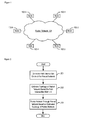
- Figure 1 depicts a schematic diagram of the illustrative embodiment of the present invention.
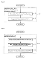
- Figure 2 depicts a flowchart of the salient tasks associated with the operation of the illustrative embodiment of the present invention.
- Figure 3 depicts a flowchart of the salient tasks associated with the operation of task 201.
- Figure 4 depicts a flowchart of the salient tasks associated with the operation of task 304.
- Figure 5 depicts a flowchart of the salient tasks associated with the operation of task 401.
- Figure 6 depicts a flowchart of the salient tasks associated with the operation of task 402.
- Figure 7 depicts a flowchart of the salient tasks associated with the operation of task 202.
- Figure 8 depicts a flowchart of the salient tasks associated with the operation of task 203.
- Figure 9 depicts a diagram of the probe pattern, which comprises 7 seconds of small packets with spacing of 5 ms.
- Figure 10a depicts a diagram of periodic interference pattern.
- Figure 10b depicts a diagram of aperiodic interference pattern.
- Figure 11a depicts a plot of z i versus tr i without interference by a periodic interference pattern.
- Figure 11b depicts a plot of z i versus tr i with interference by a periodic interference pattern.
- Figure 1 depicts a schematic diagram of the illustrative embodiment of the present invention.
- the illustrative embodiment comprises: packet network 101 and six nodes 102-1 through 102-6 connected to packet network 101.
- Packet network 101 comprises hardware and software, in well-known fashion, and is capable of transporting a stream of packets from any node to any other node. It will be clear to those skilled in the art how to make and use packet network 101.
- the network-layer topology of packet network 101 is not initially known to applications on nodes 101-1 through 101-6, but is estimated using the methodology described in detail below.
- Each of nodes 102-1 through 102-6 comprises hardware and software to enable it to perform the functionality described below.
- each of nodes 102-1 through 102-6 is identical, but it will be clear to those skilled in the art, after reading this disclosure, how to make and use alternative embodiments of the present invention in which some or all of the nodes are different.
- the illustrative embodiment comprises six nodes, it will be clear to those skilled in the art, after reading this disclosure, how to make and use alternative embodiments of the present invention that comprise any number of nodes.
- Figure 2 depicts a flowchart of the salient tasks associated with the operation of the illustrative embodiment of the present invention.
- the illustrative embodiment In task 201, the illustrative embodiment generates a path intersection matrix A for packet network 101.
- the path intersection matrix A represents the knowledge of which end-to-end paths in packet network 101 intersect and which do not.
- the illustrative embodiment empirically tests every pair of end-to-end paths in packet network 101 to determine whether they intersect or not. The process of testing every pair of end-to-end paths in packet network 101 to determine whether they intersect or not is described in detail below and in the accompanying figures.
- the set N ⁇ V are nodes 102-1 through 102-6.
- the set of directional end-to-end paths between nodes in N is represented as P .
- a path p is considered an end-to-end path if both of its end nodes are in N.
- An end-to-end path from n j ⁇ N to n j ⁇ N is represented as p i,j , where p i,j ⁇ P .
- Path intersection matrix A has dimensions
- the populated path intersection matrix A for packet network 101 is depicted in Table 1.
- Table 1 - Path Intersection Matrix A for Packet Network 101 p 1,2 p 1,3 ... p 6,4 p 6,5 p 1,2 1 1 ... 0 0 p 1,3 1 1 ... 0 0 ... ... ... ... ... ... p 6,4 0 0 ... 1 1 p 6,5 0 0 ... 0 1
- the illustrative embodiment estimates the topology of packet network 101 based on the path intersection matrix A generated in task 201.
- the topology of packet network 101 can only be estimated and not conclusively deduced because multiple networks with different, albeit similar, topologies can yield the same path intersection matrix. For many applications, however, an estimated topology, even if imperfect, is useful. It will be clear to those skilled in the art what applications require perfect knowledge of the topology and what applications can function satisfactorily with imperfect knowledge. Task 202 is described in detail below and in the accompanying figures.
- the illustrative embodiment transmits one or more packets through packet network 101 and directs those packets to be re-directed to or away from one or more specific nodes based on the topology as estimated in task 202.
- an estimate of the topology of packet network 101 is useful for many applications including, but not limited to:
- Generating Path Intersection Matrix A - Figure 3 depicts a flowchart of the salient tasks associated with the operation of task 201.
- the execution of tasks 301 through 306 generates the empirical data for one element in path intersection matrix A , and, therefore, tasks 301 through 306 are performed for each pair of paths in P .
- the illustrative embodiment transmits a stream of probe packets s a,b in a probe pattern on path p a,b .
- Figure 9 depicts a diagram of the probe pattern, which comprises one small packet every five milliseconds for a total of seven seconds. It will be clear to those skilled in the art, however, after reading this disclosure, how to make and use alternative embodiments of the present invention in which the probe pattern has any duration, packet size, packet number, and packet spacing.
- the illustrative embodiment transmits an interference stream of packets s c,d in an interference pattern on path p c,d at the same time that probe stream s a,b is transmitted on path p a,b .
- the salient desirable characteristic of the interference stream s c,d is that if it shares a network-layer node ( e . g ., queue, processor, etc .) with the probe stream s a,b , the interference stream should "interfere" with the probe stream by imparting a temporal pattern of jitter to the probe stream that corresponds to the interference pattern.
- the interference pattern is characterized by a combination of a scalar k , which represents the number of bursts in the interference pattern, and a vector of k -1 inter-burst intervals.
- Figure 10a depicts a diagram of the interference pattern, which comprises 6 bursts of 1500-byte packets transmitted back-to-back at a one second inter-burst interval. It will be clear to those skilled in the art, however, after reading this disclosure, how to make and use alternative embodiments of the present invention in which the interference pattern comprises any number of bursts of any length at any inter-burst interval, whether periodic as in Figure 10a or aperiodic as depicted in Figure 10b . Aperiodic interference patterns are advantageous over periodic interference patterns because they can be more easily distinguished from noise than periodic patterns.
- the illustrative embodiment receives the probe stream s a,b at node n b in well-known fashion, and records for each packet i its arrival time tr i .
- the illustrative embodiment detects the interference (or lack of interference) of the probe stream s a,b as received at node n b by the interference stream s c , d . This is described in detail below and in the accompanying figures.
- the illustrative embodiment deduces that paths p a,b and p c,d intersect when and only when the illustrative embodiment detects, in task 304, interference of the probe stream s a,b by the interference stream s c,d .
- the illustrative embodiment populates element A a,b,c,d of path intersection matrix A with a 1 when the illustrative embodiment deduces that paths p d,b and p c,d intersect in task 305 and with a 0 when the illustrative embodiment deduces that paths p a,b and p c,d do not intersect.
- Figure 4 depicts a flowchart of the salient tasks associated with the operation of task 304.
- Jitter pattern J a,b,c,d is a combination of a scalar m , which represents the number of groups found and a vector of m -1 inter-group intervals. This is described in detail below and in the accompanying figure.
- the illustrative embodiment compares jitter pattern J a,b,c,d to the interference pattern.
- the interference pattern is-deemed to be detected when either: (1) m ⁇ ⁇ k - ⁇ , ... , k , ..., k + ⁇ , wherein ⁇ is an integer, or (2) at least k - ⁇ of the k -1 inter-burst intervals temporally correspond to k - ⁇ of the m -1 inter-group intervals, wherein ⁇ is a positive integer.
- Task 402 is described in detail below and in the accompanying figure. It will be clear to those skilled in the art, however, after reading this disclosure, how to make and use alternative embodiments of the present invention that use another test for detecting interference of the probe stream by the interference stream.
- Test 1 is satisfied if: z i ⁇ Q 1 - 2 ⁇ D where Q 1 is the first quartile (25 th percentile) of Z and D is the difference between the 90 th and 10 th percentiles of Z .
- Test 2 is satisfied if: z i > Q 3 + 2 ⁇ D where Q 3 is the third quartile (75 th percentile) of Z.
- Test 4 is satisfied if: z i > Q 3 + 1.5 ⁇ IQR
- Test 5 is satisfied if z i is less than the 10 th percentile of Z
- test 6 is satisfied if z i is greater than the 90 th percentile of Z . It will be clear to those skilled in the art, after reading this disclosure, how to make and use alternative embodiments of the present invention that use other tests and combinations of tests for identifying the temporally-shifted packets.
- the illustrative embodiment groups the temporally-shifted packets that are within E seconds of one another into m groups, wherein E is a real number and m is a positive integer.
- E 200 ms, but it will be clear to those skilled in the art, after reading this disclosure, how to make and use alternative embodiments of the present invention which use other values of E .
- the illustrative embodiment computes the m -1 inter-group intervals where the arrival time for each group equals the median arrival time for the packets in that group.
- Compare Jitter Pattern J a,b,c,d to Interference Pattern - Figure 6 depicts a flowchart of the salient tasks associated with the operation of task 402.
- the illustrative embodiment compares k ( i.e., the number of bursts in the interference pattern) to m ( i . e ., the number of groups in jitter pattern J a,b,c,d ).
- the illustrative embodiment compares the k -1 inter-burst intervals to the m -1 inter-group intervals computed in task 401 to determine if at least k -3 inter-burst intervals temporally correspond to k -3 inter-group intervals.
- Matrix A - Figure 7 depicts a flowchart of the salient tasks associated with the operation of task 202.
- the illustrative embodiment employs four deductions, two suppositions, and a rule of thumb to estimate the network-layer topology of packet network 101 based on path intersection matrix A . By considering all of these as simultaneous truths, an estimate of the topology of packet network 101 can be made using the data in path intersection matrix A . If the application of a deduction and a supposition creates an irreconcilable conflict, the deduction overrules the supposition. Absent evidence to the contrary, a supposition is considered correct.
- the illustrative embodiment deduces the existence of at least one common node n i that is in both path p a,b and path p c,d .
- the existence of the node might or might not have been made previously through the application of the deductions and suppositions.
- path p a,b and path p c,d do not intersect
- the illustrative embodiment deduces that path p a,b and path p c,d do not share a common node.
- the existence of the node might or might not have been made previously through the application of the deductions and suppositions.
- the illustrative embodiment supposes the existence of at least one common node n i (in addition to node n a ) that is in both path p a,b and path p a,c .
- the existence of the node might or might not have been made previously through the application of the deductions and suppositions.
- the illustrative embodiment supposes the existence of at least one common node n i (in addition to node n b ) that is in both path p a,b and path p c,b .
- the existence of the node might or might not have been made previously through the application of the deductions and suppositions to other data.
- a rule of thumb applies when two paths originate or terminate at a single node.
- Figure 8 depicts a flowchart of the salient tasks associated with the operation of task 203.
- the illustrative embodiment transmits a packet or stream of packets to:
- the illustrative embodiment transmits a packet or stream of packets to:
Landscapes
- Engineering & Computer Science (AREA)
- Computer Networks & Wireless Communication (AREA)
- Signal Processing (AREA)
- Data Exchanges In Wide-Area Networks (AREA)
Abstract
Description
- The present invention relates to telecommunications in general, and, more particularly, to the maintenance and operation of telecommunications networks.
- There are many situations in the maintenance and operation of a telecommunications network when it is useful to know the logical or network-layer topology of the network. In some cases, the network-layer topology of the network is known from those who constructed it, and in some other cases the network infrastructure can provide or determine the topology. In other cases, however, the network-layer topology is not known and must be estimated based on end-to-end measurements without the support of the network infrastructure. There are techniques in the prior art that attempt to do this, but they all exhibit limitations and disadvantages. Therefore, the need exists for a new method of estimating the network-layer topology of a network using end-to-end measurements.
- The present invention provides a method for estimating the network-layer topology of a telecommunications network without some of the costs and disadvantages for doing so in the prior art. For example, the illustrative embodiment of the present invention estimates the existence and connectivity of nodes in the network based on the interference of streams of packets that traverse the network. When two streams of packets traverse two end-to-end paths in the network and one stream causes jitter in the other, it can be deduced that the two paths share a common node.
- In accordance with the illustrative embodiment, each pair of streams is transmitted with a particular temporal pattern. The pattern of one stream - the interference stream - is designed to induce jitter in the streams with which it shares a network node (e.g., a queue, a processor, etc.). The pattern of the interference stream is also designed to induced jitter that is distinguishable from background jitter. The pattern of the second stream - the probe stream - is designed to capture jitter caused by the interference stream in such a way that it can be readily distinguished from background jitter. By transmitting an interference stream and a probe stream on each pair of end-to-end paths in the network, all of the end-to-end path intersections for the network can be created.
- Using logic and supposition, the topology of the network can be estimated using the knowledge of which end-to-end paths intersect and which do not. The topology of the network can only be estimated and not conclusively deduced because networks with different network-layer topologies can yield the same combination of end-to-end path intersections. For many applications, however, an estimated topology, even if imperfect, is useful.
-
Figure 1 depicts a schematic diagram of the illustrative embodiment of the present invention. -
Figure 2 depicts a flowchart of the salient tasks associated with the operation of the illustrative embodiment of the present invention. -
Figure 3 depicts a flowchart of the salient tasks associated with the operation oftask 201. -
Figure 4 depicts a flowchart of the salient tasks associated with the operation oftask 304. -
Figure 5 depicts a flowchart of the salient tasks associated with the operation oftask 401. -
Figure 6 depicts a flowchart of the salient tasks associated with the operation oftask 402. -
Figure 7 depicts a flowchart of the salient tasks associated with the operation oftask 202. -
Figure 8 depicts a flowchart of the salient tasks associated with the operation oftask 203. -
Figure 9 depicts a diagram of the probe pattern, which comprises 7 seconds of small packets with spacing of 5 ms. -
Figure 10a depicts a diagram of periodic interference pattern. -
Figure 10b depicts a diagram of aperiodic interference pattern. -
Figure 11a depicts a plot of zi versus tri without interference by a periodic interference pattern. -
Figure 11b depicts a plot of zi versus tri with interference by a periodic interference pattern. -
Figure 1 depicts a schematic diagram of the illustrative embodiment of the present invention. The illustrative embodiment comprises:packet network 101 and six nodes 102-1 through 102-6 connected topacket network 101. -
Packet network 101 comprises hardware and software, in well-known fashion, and is capable of transporting a stream of packets from any node to any other node. It will be clear to those skilled in the art how to make and usepacket network 101. In accordance with the illustrative embodiment, the network-layer topology ofpacket network 101 is not initially known to applications on nodes 101-1 through 101-6, but is estimated using the methodology described in detail below. - Each of nodes 102-1 through 102-6 comprises hardware and software to enable it to perform the functionality described below. In accordance with the illustrative embodiment, each of nodes 102-1 through 102-6 is identical, but it will be clear to those skilled in the art, after reading this disclosure, how to make and use alternative embodiments of the present invention in which some or all of the nodes are different. Although the illustrative embodiment comprises six nodes, it will be clear to those skilled in the art, after reading this disclosure, how to make and use alternative embodiments of the present invention that comprise any number of nodes.
-
Figure 2 depicts a flowchart of the salient tasks associated with the operation of the illustrative embodiment of the present invention. - In
task 201, the illustrative embodiment generates a path intersection matrix A forpacket network 101. The path intersection matrix A represents the knowledge of which end-to-end paths inpacket network 101 intersect and which do not. To populate the path intersection matrix A, the illustrative embodiment empirically tests every pair of end-to-end paths inpacket network 101 to determine whether they intersect or not. The process of testing every pair of end-to-end paths inpacket network 101 to determine whether they intersect or not is described in detail below and in the accompanying figures. - In accordance with the illustrative embodiment, the following notation is used.
Packet network 101 is represented as a graph G = (V,E) where V is the set of nodes (routers and hosts) and E is the set of edges representing network-layer connectivity between the nodes on V. The set N ⊂ V are nodes 102-1 through 102-6. The set of directional end-to-end paths between nodes in N is represented as P. A path p is considered an end-to-end path if both of its end nodes are in N. The cardinality of P is |P| = |N| x (|N|-1). An end-to-end path from n j ∈ N to n j ∈ N is represented as p i,j, where p i,j ∈ P. - Path intersection matrix A has dimensions |P| x |P|. Each element Aa,b,c,d = 1 if pa,b ∈ P and pc,d ∈ P intersect at the network layer, and Aa,b,c,d = 0 otherwise. The populated path intersection matrix A for
packet network 101 is depicted in Table 1.Table 1 - Path Intersection Matrix A for Packet Network 101 p1,2 p1,3 ... p6,4 p6,5 p1,2 1 1 ... 0 0 p 1,31 1 ... 0 0 ... ... ... ... ... ... p6,4 0 0 ... 1 1 p 6,50 0 ... 0 1 - Although the illustrative embodiment empirically tests every pair of end-to-end paths in
packet network 101 to determine whether they intersect or not, it will be clear to those skilled in the art, after reading this disclosure, how to make and use alternative embodiments of the present invention which empirically tests fewer than every pair of end-to-end paths inpacket network 101. - In
task 202, the illustrative embodiment estimates the topology ofpacket network 101 based on the path intersection matrix A generated intask 201. The topology ofpacket network 101 can only be estimated and not conclusively deduced because multiple networks with different, albeit similar, topologies can yield the same path intersection matrix. For many applications, however, an estimated topology, even if imperfect, is useful. It will be clear to those skilled in the art what applications require perfect knowledge of the topology and what applications can function satisfactorily with imperfect knowledge.Task 202 is described in detail below and in the accompanying figures. - In
task 203, the illustrative embodiment transmits one or more packets throughpacket network 101 and directs those packets to be re-directed to or away from one or more specific nodes based on the topology as estimated intask 202. As is well known to those skilled in the art, an estimate of the topology ofpacket network 101 is useful for many applications including, but not limited to: - i. transmitting one or more packets to transit specific nodes and to avoid specific nodes for the purposes of fault avoidance, and
- ii. transmitting redundant one or more packets to transit alternative paths and nodes, and
- iii. transmitting one or more packets to transit nodes that are "closer" than other nodes.
- Generating Path Intersection Matrix A -
Figure 3 depicts a flowchart of the salient tasks associated with the operation oftask 201. The execution oftasks 301 through 306 generates the empirical data for one element in path intersection matrix A, and, therefore,tasks 301 through 306 are performed for each pair of paths in P. - In
task 301, the illustrative embodiment transmits a stream of probe packets sa,b in a probe pattern on path pa,b.Figure 9 depicts a diagram of the probe pattern, which comprises one small packet every five milliseconds for a total of seven seconds. It will be clear to those skilled in the art, however, after reading this disclosure, how to make and use alternative embodiments of the present invention in which the probe pattern has any duration, packet size, packet number, and packet spacing. - In
task 302, the illustrative embodiment transmits an interference stream of packets sc,d in an interference pattern on path pc,d at the same time that probe stream sa,b is transmitted on path pa,b. The salient desirable characteristic of the interference stream sc,d is that if it shares a network-layer node (e.g., queue, processor, etc.) with the probe stream sa,b, the interference stream should "interfere" with the probe stream by imparting a temporal pattern of jitter to the probe stream that corresponds to the interference pattern. In accordance with the illustrative embodiment, the interference pattern is characterized by a combination of a scalar k, which represents the number of bursts in the interference pattern, and a vector of k-1 inter-burst intervals. -
Figure 10a depicts a diagram of the interference pattern, which comprises 6 bursts of 1500-byte packets transmitted back-to-back at a one second inter-burst interval. It will be clear to those skilled in the art, however, after reading this disclosure, how to make and use alternative embodiments of the present invention in which the interference pattern comprises any number of bursts of any length at any inter-burst interval, whether periodic as inFigure 10a or aperiodic as depicted inFigure 10b . Aperiodic interference patterns are advantageous over periodic interference patterns because they can be more easily distinguished from noise than periodic patterns. - In
task 303, the illustrative embodiment receives the probe stream sa,b at node nb in well-known fashion, and records for each packet i its arrival time tri . - In
task 304, the illustrative embodiment detects the interference (or lack of interference) of the probe stream sa,b as received at node nb by the interference stream sc,d. This is described in detail below and in the accompanying figures. - In
task 305, the illustrative embodiment deduces that paths pa,b and pc,d intersect when and only when the illustrative embodiment detects, intask 304, interference of the probe stream sa,b by the interference stream sc,d. - In
task 306, the illustrative embodiment populates element Aa,b,c,d of path intersection matrix A with a 1 when the illustrative embodiment deduces that paths pd,b and pc,d intersect intask 305 and with a 0 when the illustrative embodiment deduces that paths pa,b and pc,d do not intersect. - Although the illustrative embodiment empirically tests two pairs of end-to-end paths at a time, it will be clear to those skilled in the art, after reading this disclosure, how to empirically test a plurality of pairs of end-to-end paths using multiple probe streams and a single interference stream. Furthermore, it will be clear to those skilled in the art, after reading, this disclosure, how to empirically test a plurality of end-to-end paths using one or more probe streams and multiple, distinguishable interference streams.
-
Figure 4 depicts a flowchart of the salient tasks associated with the operation oftask 304. - In
task 401, the illustrative embodiment generates jitter pattern Ja,b,c,d based on probe stream sa,b and interference stream sc,d . Jitter pattern Ja,b,c,d is a combination of a scalar m, which represents the number of groups found and a vector of m-1 inter-group intervals. This is described in detail below and in the accompanying figure. - In
task 402, the illustrative embodiment compares jitter pattern Ja,b,c,d to the interference pattern. In accordance with the illustrative embodiment, the interference pattern is-deemed to be detected when either: (1) m ∈ {k-Δ, ... ,k, ..., k+Δ}, wherein Δ is an integer, or (2) at least k-Ψ of the k-1 inter-burst intervals temporally correspond to k-Ψ of the m-1 inter-group intervals, wherein Ψ is a positive integer. In accordance with the illustrative embodiment, Δ=1 and Ψ=3, but it will be clear to those skilled in the art, after reading, this disclosure, how to make and use alternative embodiments of the present invention that have any value of Δ (e.g., Δ=0, 1, 2, 3, 4, 5, 10, etc.) and any value of Ψ (e.g., Ψ=1, 2, 3, 4, 5, 10, etc.).Task 402 is described in detail below and in the accompanying figure. It will be clear to those skilled in the art, however, after reading this disclosure, how to make and use alternative embodiments of the present invention that use another test for detecting interference of the probe stream by the interference stream. - Generate Jitter Pattern J a,b,c,d -
Figure 5 depicts a flowchart of the salient tasks associated with the operation oftask 401. - In
task 501, the illustrative embodiment identifies the temporally-shifted packets in the probe stream sa,b by calculating the temporal shift zj for each packet i in the probe stream transmitted by node na at time tsi and received node nb at time trj :
wherein ts(i-1) and tr(i-1) are the sending and receiving times of the i-1th packet, respectively. When there is no interference caused by interference stream sc,d, a plot of zi versus tri looks like that depicted inFigure 11a , but when there is interference, a plot of zj versus tri looks something like that depicted inFigure 11b . InFigure 11b , the six groups of temporally-shifted packets, caused by the six periodic bursts in interference stream sc,d, respectively, are clearly visible and distinguishable from the unshifted packets. Quantitatively, however, packet i is only considered temporally shifted if it satisfies at least one ofTests 1 though 4 and eitherTest 5 orTest 6. -
Test 1 is satisfied if:
where Q1 is the first quartile (25th percentile) of Z and D is the difference between the 90th and 10th percentiles of Z. -
Test 2 is satisfied if:
where Q3 is the third quartile (75th percentile) of Z. -
Test 3 is satisfied if:
where IQR = Q 3 -Q 1. -
Test 4 is satisfied if:
-
Test 5 is satisfied if zi is less than the 10th percentile of Z, andtest 6 is satisfied if zi is greater than the 90th percentile of Z. It will be clear to those skilled in the art, after reading this disclosure, how to make and use alternative embodiments of the present invention that use other tests and combinations of tests for identifying the temporally-shifted packets. - In
task 502, the illustrative embodiment groups the temporally-shifted packets that are within E seconds of one another into m groups, wherein E is a real number and m is a positive integer. In accordance with the illustrative embodiment, E = 200 ms, but it will be clear to those skilled in the art, after reading this disclosure, how to make and use alternative embodiments of the present invention which use other values of E. - In
task 503, the illustrative embodiment computes the m-1 inter-group intervals where the arrival time for each group equals the median arrival time for the packets in that group. - Compare Jitter Pattern J a,b,c,d to Interference Pattern-
Figure 6 depicts a flowchart of the salient tasks associated with the operation oftask 402. - In
task 601, the illustrative embodiment compares k (i.e., the number of bursts in the interference pattern) to m (i.e., the number of groups in jitter pattern Ja,b,c,d ). - In
task 602, the illustrative embodiment compares the k-1 inter-burst intervals to the m-1 inter-group intervals computed intask 401 to determine if at least k-3 inter-burst intervals temporally correspond to k-3 inter-group intervals. - Matrix A -
Figure 7 depicts a flowchart of the salient tasks associated with the operation oftask 202. The illustrative embodiment employs four deductions, two suppositions, and a rule of thumb to estimate the network-layer topology ofpacket network 101 based on path intersection matrix A. By considering all of these as simultaneous truths, an estimate of the topology ofpacket network 101 can be made using the data in path intersection matrix A. If the application of a deduction and a supposition creates an irreconcilable conflict, the deduction overrules the supposition. Absent evidence to the contrary, a supposition is considered correct. - In
task 701, when path pa,b and path pc,d intersect, the illustrative embodiment deduces the existence of at least one common node ni that is in both path pa,b and path pc,d . The existence of the node might or might not have been made previously through the application of the deductions and suppositions. - In
task 702, when path pa,b and path pc,d do not intersect, the illustrative embodiment deduces that path pa,b and path pc,d do not share a common node. The existence of the node might or might not have been made previously through the application of the deductions and suppositions. - In
task 703, when both path pa,b and path pa,c intersect path pd,e, the illustrative embodiment supposes the existence of at least one common node ni (in addition to node na ) that is in both path pa,b and path pa,c . Here too, the existence of the node might or might not have been made previously through the application of the deductions and suppositions. - In
task 704, when both path pa,b and path pc,b intersect path pd,e, the illustrative embodiment supposes the existence of at least one common node ni (in addition to node nb) that is in both path pa,b and path pc,b . Here too, the existence of the node might or might not have been made previously through the application of the deductions and suppositions to other data. - In
task 705, when (1) path pa,b and path pd,e intersect at a common node ni, and (2) path pa,c does not intersect path pd,e , the illustrative embodiment deduces that path pa,c does not comprise node ni . This deduction is useful to rebut a supposition made in eithertask - In
task 706, when (1) path pa,b and path pd,e intersect at a common node ni , and (2) path pc,b does not intersect path pd,e , the illustrative embodiment deduces that path pc,b does not comprise.node ni . This deduction is useful to rebut a supposition made in eithertask - Additionally, a rule of thumb applies when two paths originate or terminate at a single node. The larger the number of paths that both paths intersect (and fail to intersect), the longer the segment (i.e., edges and nodes) shared by the two paths. This can be determined by assessing the similarity between the two column vectors in the path intersection matrix that correspond to the two paths. In other words, if two paths originate or terminate at a single node, a low Hamming distance between the two column vectors for those paths suggests a long shared segment between the paths.
- It will be clear to those skilled in the art, after reading this disclosure, how to estimate the topology of any network based on these deductions, suppositions, and the rule of thumb.
-
Figure 8 depicts a flowchart of the salient tasks associated with the operation oftask 203. - In
task 801, the illustrative embodiment transmits a packet or stream of packets to: - (a) transit a first node n1 and not transit a second node n2 in some circumstances (e.g., when the jitter pattern corresponds to the temporal pattern, etc.); and
- (b) transit the second node n2 and not transit the first node n1 in some other circumstances (e.g., when the jitter pattern fails to correspond to the temporal pattern, etc.).
- In
task 802, the illustrative embodiment transmits a packet or stream of packets to: - (a) transit both a first node n1 and a second node n2 in some circumstances (e.g., when the jitter pattern corresponds to the temporal pattern, etc.); and
- (b) transit neither second node n2 nor the first node n1 in some other circumstances (e.g., when the jitter pattern fails to correspond to the temporal pattern, etc.).
- It is to be understood that the disclosure teaches just one example of the illustrative embodiment and that many variations of the invention can easily be devised by those skilled in the art after reading this disclosure and that the scope of the present invention is to be determined by the following claims.
Claims (6)
- A method comprising:detecting interference by a first stream of packets on a second stream of packets in a packet network, wherein the second stream of packets is transmitted from a first node n1 to a second node n2 via a first path p1,2 in the packet network;detecting interference by the first stream of packets on a third stream of packets in the packet network, wherein the third stream of packets is transmitted from the first node n1 to a third node n3 via a second path p1,3 in the packet network;deducing that both the first path p1,2 and the second path p1,3 comprise a fourth node n4 because both the second stream of packets and the third stream of packets are interfered by the first stream of packets; andtransmitting a packet to transit the fourth node n4 .
- The method of claim 1 further comprising:detecting no interference by the first stream of packets on a fourth stream of packets in the packet network, wherein the fourth stream of packets is transmitted from the first node n1 to a fifth node n5 via a third path p1,5 in the packet network;deducing that the third path p1,5 comprises a sixth node n6 that is not in the first path p1,2 or the second path p1,3 because the fourth stream of packets is not interfered by the first stream of packets; andtransmitting a second packet to transit the sixth node n6 .
- A method comprising:detecting interference by a first stream of packets on a second stream of packets in a packet network, wherein the second stream of packets is transmitted from a first node n1 to a second node n2 via a first path p1,2 in the packet network;detecting interference by the first stream of packets on a third stream of packets in the packet network, wherein the third stream of packets is transmitted from a third node n3 to the second node n2 via a second path p3,2 in the packet network;deducing that both the first path p1,2 and the second path p3,2 comprise a fourth node n4 because both the second stream of packets and the third stream of packets are interfered by the first stream of packets; andtransmitting a first packet to transit the fourth node n4 .
- The method of claim 3 further comprising:detecting no interference by the first stream of packets on a fourth stream of packets in the packet network, wherein the fourth stream of packets is transmitted from a fifth node n5 to the second node n2 via a third path p5,2 in the packet network;deducing that the third path p5,2 comprises a sixth node n6 that is not in the first path p1,2 or the second path p3,2 because the fourth stream of packets is not interfered by the first stream of packets; andtransmitting a second packet to transit the sixth node n6 .
- A method comprising:detecting interference by a first stream of packets on a second stream of packets in a packet network, wherein the second stream of packets is transmitted from a first node n1 to a second node n2 via a first path p1,2 in the packet network;detecting no interference by the first stream of packets on a third stream of packets in the packet network, wherein the third stream of packets is transmitted from the first node n1 to a third node n3 via a second path p1,3 in the packet network;deducing that the first path p1,2 comprises a fourth node n4 and that the second path p1,3 does not comprise the fourth node n4 because the second stream of packets is interfered by the first stream of packets but the third stream of packets is not interfered by the first stream of packets; andtransmitting a first packet to transit the fourth node n4 .
- A method comprising:detecting interference by a first stream of packets on a second stream of packets in a packet network, wherein the second stream of packets is transmitted from a first node n1 to a second node n2 via a first path p1,2 in the packet network;detecting no interference by the first stream of packets on a third stream of packets in the packet network, wherein the third stream of packets is transmitted from a third node n3 to the second node n2 via a second path p3,2 in the packet network;deducing that the first path p1,2 comprises a fourth node n4 and that the second path p 3,2 does not comprise the fourth node n4 because the second stream of packets is interfered by the first stream of packets but the third stream of packets is not interfered by the first stream of packets; andtransmitting a first packet to transit the fourth node n4 .
Applications Claiming Priority (1)
| Application Number | Priority Date | Filing Date | Title |
|---|---|---|---|
| US11/939,297 US7720005B2 (en) | 2007-11-13 | 2007-11-13 | Estimating network-layer topology using end-to-end measurements |
Publications (2)
| Publication Number | Publication Date |
|---|---|
| EP2061185A1 true EP2061185A1 (en) | 2009-05-20 |
| EP2061185B1 EP2061185B1 (en) | 2012-02-15 |
Family
ID=40474814
Family Applications (1)
| Application Number | Title | Priority Date | Filing Date |
|---|---|---|---|
| EP08168860A Not-in-force EP2061185B1 (en) | 2007-11-13 | 2008-11-11 | Estimating network-layer topology using end-to-end measurements |
Country Status (4)
| Country | Link |
|---|---|
| US (1) | US7720005B2 (en) |
| EP (1) | EP2061185B1 (en) |
| KR (1) | KR101419064B1 (en) |
| CA (1) | CA2641197A1 (en) |
Cited By (1)
| Publication number | Priority date | Publication date | Assignee | Title |
|---|---|---|---|---|
| CN104301178A (en) * | 2014-10-11 | 2015-01-21 | 东南大学 | Estimator and Method for Complex Dynamic Network Topology Structure Based on Steady State Migration Control |
Families Citing this family (3)
| Publication number | Priority date | Publication date | Assignee | Title |
|---|---|---|---|---|
| JP5577968B2 (en) * | 2010-09-06 | 2014-08-27 | 富士通株式会社 | Network investigation method and network investigation apparatus |
| US10231134B1 (en) * | 2017-09-29 | 2019-03-12 | At&T Intellectual Property I, L.P. | Network planning based on crowd-sourced access point data for 5G or other next generation network |
| US11765041B1 (en) * | 2022-09-15 | 2023-09-19 | Huawei Technologies Co., Ltd. | Methods and systems for implementing a high radix network topology |
Family Cites Families (9)
| Publication number | Priority date | Publication date | Assignee | Title |
|---|---|---|---|---|
| JPH05204876A (en) * | 1991-10-01 | 1993-08-13 | Hitachi Ltd | Hierarchical network and multiprocessor using the same |
| US6256295B1 (en) * | 1997-09-25 | 2001-07-03 | Nortel Networks Limited | Method and apparatus for determining multiple minimally-overlapping paths between nodes in a network |
| SG97934A1 (en) * | 2000-09-13 | 2003-08-20 | Mediaring Ltd | Quality of transmission across packet-based networks |
| CA2426181A1 (en) * | 2000-10-17 | 2002-04-25 | Computer Associates Think, Inc. | Method and apparatus for selectively displaying layered network diagrams |
| US6904020B1 (en) * | 2000-11-01 | 2005-06-07 | Agilent Technologies, Inc. | System and method for monitoring communication networks using data stream characterization |
| US6947392B2 (en) * | 2001-07-16 | 2005-09-20 | International Business Machines Corporation | Methods and arrangements for building a subsource address multicast distribution tree using traced routes |
| KR101295207B1 (en) * | 2003-09-15 | 2013-08-09 | 지고 코포레이션 | Interferometric analysis of surfaces |
| US7567523B2 (en) * | 2004-01-29 | 2009-07-28 | Microsoft Corporation | System and method for network topology discovery |
| JP2006165643A (en) * | 2004-12-02 | 2006-06-22 | Kddi Corp | COMMUNICATION SYSTEM, DELAY INSERTION SERVER, BACKUP SERVER, AND COMMUNICATION CONTROL DEVICE |
-
2007
- 2007-11-13 US US11/939,297 patent/US7720005B2/en not_active Expired - Fee Related
-
2008
- 2008-10-16 CA CA002641197A patent/CA2641197A1/en not_active Abandoned
- 2008-11-11 EP EP08168860A patent/EP2061185B1/en not_active Not-in-force
- 2008-11-12 KR KR1020080111994A patent/KR101419064B1/en not_active Expired - Fee Related
Non-Patent Citations (5)
| Title |
|---|
| COATES ET AL.: "Maximum likelihood network topology identification from edge-based unicast measurements", ACM SIGMETRICS PERFORMANCE EVALUATION REVIEW |
| COATES M ET AL.: "Maximum likelihood network topology identification from edge-based unicast measurements", ACM SIGMETRICS PERFORMANCE EVALUATION REVIEW, vol. 30, no. 1, 15 June 2002 (2002-06-15) - 19 June 2002 (2002-06-19), Los Angeles, CA, pages 11 - 20, XP002522849, ISSN: 01635999, Retrieved from the Internet <URL:http://doi.acm.org/10.1145/511399.511337> [retrieved on 20090405] * |
| KARACALI B ET AL: "Network-wide inference of end-to-end path intersections", NETWORK OPERATIONS AND MANAGEMENT SYMPOSIUM, 2008. NOMS 2008. IEEE, IEEE, PISCATAWAY, NJ, USA, 7 April 2008 (2008-04-07), pages 168 - 175, XP031290515, ISBN: 978-1-4244-2065-0 * |
| MICHAEL G RABBAT ET AL: "Multiple-Source Internet Tomography", IEEE JOURNAL ON SELECTED AREAS IN COMMUNICATIONS, IEEE SERVICE CENTER, PISCATAWAY, US, vol. 24, no. 12, 1 December 2006 (2006-12-01), pages 2221 - 2234, XP011151085, ISSN: 0733-8716 * |
| RABBAT ET AL.: "Multiple-Source Internet Tomography", IEEE JOURNAL ON SELECTED AREAS IN COMMUNICATIONS |
Cited By (2)
| Publication number | Priority date | Publication date | Assignee | Title |
|---|---|---|---|---|
| CN104301178A (en) * | 2014-10-11 | 2015-01-21 | 东南大学 | Estimator and Method for Complex Dynamic Network Topology Structure Based on Steady State Migration Control |
| CN104301178B (en) * | 2014-10-11 | 2017-08-25 | 东南大学 | The complex dynamic network topological structure estimator and method of control are migrated based on stable state |
Also Published As
| Publication number | Publication date |
|---|---|
| US7720005B2 (en) | 2010-05-18 |
| KR101419064B1 (en) | 2014-07-11 |
| US20090122720A1 (en) | 2009-05-14 |
| KR20090049547A (en) | 2009-05-18 |
| EP2061185B1 (en) | 2012-02-15 |
| CA2641197A1 (en) | 2009-05-13 |
Similar Documents
| Publication | Publication Date | Title |
|---|---|---|
| JP5120784B2 (en) | Method for estimating quality degradation points on a network in a communication network system | |
| EP3188412B1 (en) | Method, apparatus, and system for implementing delay measurement | |
| US7752666B2 (en) | Detection of routing loops based on time-to-live expiries | |
| US7385931B2 (en) | Detection of network misconfigurations | |
| US7941690B2 (en) | Reliable fault resolution in a cluster | |
| Dhamdhere et al. | NetDiagnoser: Troubleshooting network unreachabilities using end-to-end probes and routing data | |
| US7995574B2 (en) | Detection of forwarding problems for external prefixes | |
| CN100553204C (en) | Signature matching method and device for network diagnosis | |
| EP2795841B1 (en) | Method and arrangement for fault analysis in a multi-layer network | |
| EP3707862B1 (en) | Method and sytem for detecting sources of computer network failures | |
| CN108683602B (en) | Data center network load balancing method | |
| EP2061185B1 (en) | Estimating network-layer topology using end-to-end measurements | |
| WO2014003889A1 (en) | Deterministic network failure detection | |
| Cunha et al. | Measurement methods for fast and accurate blackhole identification with binary tomography | |
| US7720004B2 (en) | Interfering packet streams in packet networks | |
| US7961647B2 (en) | Detecting interfering packet streams in packet networks | |
| CN106961344B (en) | Network fault detection method and device | |
| US20150341242A1 (en) | Transmission monitoring method and device | |
| JP6378653B2 (en) | Service impact cause estimation apparatus, service impact cause estimation program, and service impact cause estimation method | |
| Bai et al. | A two-stage approach for network monitoring | |
| US20170132055A1 (en) | Determining Physical Layer Error Signatures of a Communications Link | |
| Fei et al. | Accurate and effective inference of network link loss from unicast end-to-end measurements | |
| JP5557869B2 (en) | Packet loss number measuring apparatus, method and program | |
| Pan et al. | Identification of multipath routing based on end-to-end packet order | |
| Ghita | Practical Network Tomography |
Legal Events
| Date | Code | Title | Description |
|---|---|---|---|
| PUAI | Public reference made under article 153(3) epc to a published international application that has entered the european phase |
Free format text: ORIGINAL CODE: 0009012 |
|
| AK | Designated contracting states |
Kind code of ref document: A1 Designated state(s): AT BE BG CH CY CZ DE DK EE ES FI FR GB GR HR HU IE IS IT LI LT LU LV MC MT NL NO PL PT RO SE SI SK TR |
|
| AX | Request for extension of the european patent |
Extension state: AL BA MK RS |
|
| 17P | Request for examination filed |
Effective date: 20090618 |
|
| 17Q | First examination report despatched |
Effective date: 20090717 |
|
| AKX | Designation fees paid |
Designated state(s): DE FR GB |
|
| GRAP | Despatch of communication of intention to grant a patent |
Free format text: ORIGINAL CODE: EPIDOSNIGR1 |
|
| GRAS | Grant fee paid |
Free format text: ORIGINAL CODE: EPIDOSNIGR3 |
|
| GRAA | (expected) grant |
Free format text: ORIGINAL CODE: 0009210 |
|
| AK | Designated contracting states |
Kind code of ref document: B1 Designated state(s): DE FR GB |
|
| REG | Reference to a national code |
Ref country code: GB Ref legal event code: FG4D |
|
| REG | Reference to a national code |
Ref country code: DE Ref legal event code: R096 Ref document number: 602008013428 Country of ref document: DE Effective date: 20120419 |
|
| PLBE | No opposition filed within time limit |
Free format text: ORIGINAL CODE: 0009261 |
|
| STAA | Information on the status of an ep patent application or granted ep patent |
Free format text: STATUS: NO OPPOSITION FILED WITHIN TIME LIMIT |
|
| 26N | No opposition filed |
Effective date: 20121116 |
|
| PGFP | Annual fee paid to national office [announced via postgrant information from national office to epo] |
Ref country code: FR Payment date: 20121130 Year of fee payment: 5 |
|
| REG | Reference to a national code |
Ref country code: DE Ref legal event code: R097 Ref document number: 602008013428 Country of ref document: DE Effective date: 20121116 |
|
| REG | Reference to a national code |
Ref country code: FR Ref legal event code: ST Effective date: 20140731 |
|
| PG25 | Lapsed in a contracting state [announced via postgrant information from national office to epo] |
Ref country code: FR Free format text: LAPSE BECAUSE OF NON-PAYMENT OF DUE FEES Effective date: 20131202 |
|
| REG | Reference to a national code |
Ref country code: DE Ref legal event code: R082 Ref document number: 602008013428 Country of ref document: DE Representative=s name: PAGE, WHITE & FARRER GERMANY LLP, DE |
|
| PGFP | Annual fee paid to national office [announced via postgrant information from national office to epo] |
Ref country code: GB Payment date: 20201127 Year of fee payment: 13 Ref country code: DE Payment date: 20201127 Year of fee payment: 13 |
|
| REG | Reference to a national code |
Ref country code: DE Ref legal event code: R079 Ref document number: 602008013428 Country of ref document: DE Free format text: PREVIOUS MAIN CLASS: H04L0012240000 Ipc: H04L0041000000 |
|
| REG | Reference to a national code |
Ref country code: DE Ref legal event code: R119 Ref document number: 602008013428 Country of ref document: DE |
|
| GBPC | Gb: european patent ceased through non-payment of renewal fee |
Effective date: 20211111 |
|
| PG25 | Lapsed in a contracting state [announced via postgrant information from national office to epo] |
Ref country code: GB Free format text: LAPSE BECAUSE OF NON-PAYMENT OF DUE FEES Effective date: 20211111 Ref country code: DE Free format text: LAPSE BECAUSE OF NON-PAYMENT OF DUE FEES Effective date: 20220601 |