EP2060942B1 - Modular separating box for light guides and a system of modular separating boxes for light guides - Google Patents
Modular separating box for light guides and a system of modular separating boxes for light guides Download PDFInfo
- Publication number
- EP2060942B1 EP2060942B1 EP08019463A EP08019463A EP2060942B1 EP 2060942 B1 EP2060942 B1 EP 2060942B1 EP 08019463 A EP08019463 A EP 08019463A EP 08019463 A EP08019463 A EP 08019463A EP 2060942 B1 EP2060942 B1 EP 2060942B1
- Authority
- EP
- European Patent Office
- Prior art keywords
- modular separating
- modular
- boxes
- box
- chamber
- Prior art date
- Legal status (The legal status is an assumption and is not a legal conclusion. Google has not performed a legal analysis and makes no representation as to the accuracy of the status listed.)
- Active
Links
Images





Classifications
-
- G—PHYSICS
- G02—OPTICS
- G02B—OPTICAL ELEMENTS, SYSTEMS OR APPARATUS
- G02B6/00—Light guides; Structural details of arrangements comprising light guides and other optical elements, e.g. couplings
- G02B6/44—Mechanical structures for providing tensile strength and external protection for fibres, e.g. optical transmission cables
- G02B6/4439—Auxiliary devices
- G02B6/444—Systems or boxes with surplus lengths
- G02B6/4452—Distribution frames
- G02B6/44526—Panels or rackmounts covering a whole width of the frame or rack
-
- G—PHYSICS
- G02—OPTICS
- G02B—OPTICAL ELEMENTS, SYSTEMS OR APPARATUS
- G02B6/00—Light guides; Structural details of arrangements comprising light guides and other optical elements, e.g. couplings
- G02B6/44—Mechanical structures for providing tensile strength and external protection for fibres, e.g. optical transmission cables
- G02B6/4439—Auxiliary devices
- G02B6/444—Systems or boxes with surplus lengths
- G02B6/44528—Patch-cords; Connector arrangements in the system or in the box
Definitions
- the present invention relates generally to a modular separating box for light guides and a system of modular separating boxes for light guides, designed for the rapid connection of light guide courses.
- a walled light guide separating box as described in U.S. Patent Application Publication No. 2001/036351 has a metal housing basically having perpendicular walls comprised of side, upper, lower and rear walls, as well as a first front cover for closing the chamber of incoming light guides and a second front cover for closing the chamber of outgoing light guides. Both chambers located inside the housing are separated by a panel connected basically parallel to the side wall and extending between the upper and lower walls. The first cover is connected to the side wall by hinges so that it is perpendicular to the side wall in the closed state.
- the second front cover is connected by hinges to the rear wall so that in the closed state it forms a second side wall opposite the first side wall, and the front wall is an elongation of the first cover.
- the covers can be connected in other implementation examples to the housing without hinges with the aid of latches or clips.
- a walled light guide separating box as described in U.S. Patent No. 5,823,646 is also known. It has a housing containing a rear panel, upper, lower and side walls and front doors that open downward and two side doors on both sides of the front doors that open to the side. The side doors are latched on the front doors such that the opening of the front doors simultaneously causes the side doors to open.
- FIG. PL53218 Another separating box solution known from the prior art is the housing represented in utility model No. PL53218 , which has a perpendicular-walled shape containing elements fastened rotatably.
- the housing has a rotatably mounted cover that is the front movable wall.
- the covers are fastened on the inside with holders to steel connectors.
- inside the covers/doors there is a free space constituting a container for storage of light guides, fastened with cable holders.
- a bracket having holes for turning the separation connectors and a set of connection clips for controlling the cables introduced into the housing and going out of the housing are provided.
- a modular separating box for light guides containing a housing with chambers, a connection panel, and a small mounted doors in accordance with the invention comprising a receiving chamber, and/or a sending chamber, and/or a connection chamber, enclosed by individual doors.
- the modular separating box has at least one wall with at least one movable plate, and at least one connection panel, which forms a wall of the receiving chamber and/or sending chamber.
- the modular separating box comprises fastening elements for connecting one modular separating box to successive modular separating boxes to form a modular arrangement of modular separating boxes, wherein the fastening elements are placed on the upper surface, and/or lower surface and/or side surface of the modular separating box housing.
- the modular separating box housing is perpendicular-walled, and the movable plate is the lower wall and/or upper wall and/or the side wall.
- the connection panel constitutes an element of the external wall of the modular separating box or an element delimiting the pitch plane of the box on the sending and/or receiving and/or connection plane.
- the connection panel constitutes the bracket of the panel of adapters or the cover of the light guide cable.
- the connection panel is connected rotatably to the rear wall.
- the receiving and/or connection chamber is connected to at least one sending chamber.
- the connection chamber constitutes a part or all of the receiving chamber.
- the doors are connected in an articulated manner to the receiving and sending chambers.
- the chamber doors have edges with the connecting elements that permit forming a common surface.
- the modular separating box is preferably a walled box.
- the system of modular separating boxes for light guides comprises a set of interconnected modular separating boxes connected to each other involving sending chambers, and/or receiving chambers and/or connection chambers, having at least one movable wall for further connections including at least one movable plate, in which the connection panel forms a wall of the receiving chamber and/or sending chamber.
- Fastening elements are located .on the surfaces of the box housing for connecting one modular separating box to subsequent modular separating boxes for creating a modular arrangement of separating boxes, in which case the system contains at least one sending chamber and at least one receiving chamber and/or connection chamber.
- the system preferably contains at least one sending chamber and one receiving chamber.
- the sending chambers are located inside and/or below and/or above and/or around the receiving chamber.
- the connection chamber constitutes part or all of the receiving chamber.
- system of modular separating boxes for light guides has separate spaces for storage of light guide cables.
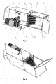
- Figure 1 the inside of the modular separating box with a receiving chamber in a first implementation example with a panel bracket;
- Figure 2 the lower surface of the modular separating box with a receiving chamber in a first implementation example with a panel bracket;
- Figure 3 the inside of the modular separating box with a sending chamber in a first implementation example with a panel bracket;
- Figure 4 the lower surface of the modular separating box with a sending chamber in a first implementation example with a panel bracket;
- Figure 5 the inside of the modular separating box with a receiving chamber in a first implementation example with the cover of the light guide cables;
- Figure 6 the lower surface of the modular separating box with a receiving chamber in a first implementation example with the cover of the light guide cables;
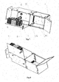
- Figure 7 the inside of the modular separating box with a sending chamber in a first implementation example with the cover of the light guide cables;
- Figure 8 the lower surface of the modular separating box with a sending chamber in a first implementation example with the cover of the light guide cables;
- Figure 9 closed modular separating box with a receiving chamber connected to three modular separating boxes with sending chambers in a first implementation example with a separate space for storing the light guide cables;
- Figure 10 modular separating box with a receiving chamber connected to three modular separating boxes with sending chambers in a first implementation example with open doors of the receiving chamber and the connection chamber;
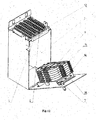
- Figure 11 modular separating box with a receiving chamber with open doors connected to two modular separating boxes with sending chambers in a second implementation example
- Figure 12 the i nside of the modular separating box with receiving/sending chamber in a second implementation example with a panel bracket;
- Figure 13 modular separating box with receiving/sending chamber in a second implementation example with the cover of the light guide cables.
- the shape and dimensions of the modular separating box with a receiving chamber or sending chamber are identical.
- the modular separating box has a perpendicular-walled shape and contains a housing 2 with chambers, a bracket 3 of the panel 4 of adapters 5 with four rows of exchangeable panels 4 having 12 adapters 5 each, rotatably fastened doors 8 closed with a lock 7, to which a cassette 9 is fastened from the inside; it also contains a cable guide 10 (for pigtails) and a short front door 6, blocked by door 8.
- the side wall 1, which is removable to assure easy access of the preconnected cable, is connected to the bent side edges of the upper and lower part of the housing 2 with the aid of connector elements.
- the bracket 3 of the panel 4 of adapters 5 with the axis of rotation along the rear edge of the pitch plane of the housing on the chamber is located between the upper and lower part of the housing 2 in the pitch plane of the housing on two chambers parallel to the side wall 1. It is possible in this implementation to replace the bracket 3 of panel 4 of adapters 5 with the cover of the light guide cable 11.
- the lower part of the housing of the sending or receiving chamber is connected with the aid of hinges to the doors 8 along the front lower edge of this part of the housing.
- the cassette 9 is placed on the inner surface of the door 8, and the lock 7 is seated in the upper right-hand corner.
- the box has two short front doors 6 connected to the housing with the aid of hinges along the side edge of the housing, and along the upper and lower edges adjoining the short front doors 6, there are bent borders for connection to the successive element with the aid of connector elements.
- the short front doors 6 have a strip along their edge that permits blocking these doors, where the receiving box has a strip fastened along the left-side edge and for the sending box along the upper edge of the short front doors 6.
- the walls 13 are removable; a common space is thus created for the pigtails.
- the removable walls 13 are fastened to the configured side edges of the upper and lower parts of the housing 2 for the pitch plane on the chamber with clips 12.
- Catches for connecting the individual modular boxes are located on the upper and lower surfaces of the housing 2.
- the cover of the shelf 17 is connected to the shelf 17 by hinges along its upper rear edge.
- the modular separating boxes have profiled upper and lower edges for connecting the individual modular separating boxes to each other by means of clips 12.
- the doors 20 comprised of the coupling of the smaller elements 6 do not have locks.
- Figure 9 shows a modular separating box with a receiving chamber 18 connected with the modular separating boxes with sending chambers 19 with closed doors of the modular separating box with the receiving chamber 18 and closed doors of the modular separating boxes with sending chambers 19.
- the modular separating box with a receiving chamber 18 and the modular separating box with a sending chamber 19 are modular separating boxes having a perpendicular-walled form but differ in dimensions.
- the width of the modular separating box with the receiving chamber 18 is a multiple of the width of the modular separating box with the sending chamber 19, and the modular separating box with the receiving chamber 18 in this implementation example is connected to two modular separating boxes with sending chambers 19, while the third part of the lower wall of the modular separating box with the receiving chamber 18 constitutes the removable wall 13.
- the modular separating box with the receiving chamber 18 has front doors 26 fastened by hinges to the housing, enclosed by the lock 7, and inside of it, one part contains a bracket 3 with panels 4 of adapters 5 having a rotation axis and cassette 9 on the bracket of cassettes 14, and the second part has a free space for braiding pigtails.
- the modular separating box with sending chamber 19 has a perpendicular-walled shape having doors 28 with a cassette 9 located on them from the inside in a drawer 15 situated on the guide of the drawer 16. A lock 7 is seated in the doors 28 in their left-hand upper corner.
- the upper wall of the modular separating box with the sending chamber 19 constitutes the bracket 3 of the panel 4 of adapters 5 or the cover 11 of the light guide cable.
- the modular separating boxes with the sending chambers have fastening projections or lugs along the upper edges that facilitate fastening the individual elements to each other.
- the solution according to the invention makes it possible to use one modular separating box for light guides, utilized by several different operators, facilitating each operator having sole access to a separate modular separating box, and access with other operators to a common modular separating box.
Landscapes
- Physics & Mathematics (AREA)
- General Physics & Mathematics (AREA)
- Optics & Photonics (AREA)
- Light Guides In General And Applications Therefor (AREA)
- Mechanical Coupling Of Light Guides (AREA)
- Mechanical Light Control Or Optical Switches (AREA)
Abstract
Description
- This application claims benefit of priority under 35 U.S.C. § 119 of Polish Patent Application No.
P-383706 filed on November 6, 2007 - The present invention relates generally to a modular separating box for light guides and a system of modular separating boxes for light guides, designed for the rapid connection of light guide courses.
- There are many solutions for light guide-separating boxes on the market from various manufacturers.
- A walled light guide separating box as described in
U.S. Patent Application Publication No. 2001/036351 is known. It has a metal housing basically having perpendicular walls comprised of side, upper, lower and rear walls, as well as a first front cover for closing the chamber of incoming light guides and a second front cover for closing the chamber of outgoing light guides. Both chambers located inside the housing are separated by a panel connected basically parallel to the side wall and extending between the upper and lower walls. The first cover is connected to the side wall by hinges so that it is perpendicular to the side wall in the closed state. The second front cover is connected by hinges to the rear wall so that in the closed state it forms a second side wall opposite the first side wall, and the front wall is an elongation of the first cover. The covers can be connected in other implementation examples to the housing without hinges with the aid of latches or clips. - A walled light guide separating box as described in
U.S. Patent No. 5,823,646 is also known. It has a housing containing a rear panel, upper, lower and side walls and front doors that open downward and two side doors on both sides of the front doors that open to the side. The side doors are latched on the front doors such that the opening of the front doors simultaneously causes the side doors to open. - Another separating box solution known from the prior art is the housing represented in utility model No.
PL53218 - However, there is no solution that would take into account the possibility of using a walled modular separating box for light guides, utilized by several different operators and offering the possibility for each operator to have sole access to a separate modular separating box, and access with other operators to a common modular separating box. The solution according to the invention assures expansion of the separating box in both directions, from both the receiving and sending sides.
- A modular separating box for light guides containing a housing with chambers, a connection panel, and a small mounted doors in accordance with the invention comprising a receiving chamber, and/or a sending chamber, and/or a connection chamber, enclosed by individual doors. The modular separating box has at least one wall with at least one movable plate, and at least one connection panel, which forms a wall of the receiving chamber and/or sending chamber. The modular separating box comprises fastening elements for connecting one modular separating box to successive modular separating boxes to form a modular arrangement of modular separating boxes, wherein the fastening elements are placed on the upper surface, and/or lower surface and/or side surface of the modular separating box housing.
- The modular separating box housing is perpendicular-walled, and the movable plate is the lower wall and/or upper wall and/or the side wall. The connection panel constitutes an element of the external wall of the modular separating box or an element delimiting the pitch plane of the box on the sending and/or receiving and/or connection plane. Preferably, the connection panel constitutes the bracket of the panel of adapters or the cover of the light guide cable. In addition, the connection panel is connected rotatably to the rear wall.
- The receiving and/or connection chamber is connected to at least one sending chamber. In addition, the connection chamber constitutes a part or all of the receiving chamber.
- The doors are connected in an articulated manner to the receiving and sending chambers.
- The chamber doors have edges with the connecting elements that permit forming a common surface.
- The modular separating box is preferably a walled box.
- The system of modular separating boxes for light guides according to the invention comprises a set of interconnected modular separating boxes connected to each other involving sending chambers, and/or receiving chambers and/or connection chambers, having at least one movable wall for further connections including at least one movable plate, in which the connection panel forms a wall of the receiving chamber and/or sending chamber. Fastening elements are located .on the surfaces of the box housing for connecting one modular separating box to subsequent modular separating boxes for creating a modular arrangement of separating boxes, in which case the system contains at least one sending chamber and at least one receiving chamber and/or connection chamber.
- The system preferably contains at least one sending chamber and one receiving chamber. The sending chambers are located inside and/or below and/or above and/or around the receiving chamber. In addition, the connection chamber constitutes part or all of the receiving chamber.
- In a preferable implementation variant the system of modular separating boxes for light guides has separate spaces for storage of light guide cables.
- The object of the invention is presented in the implementation examples in the figures, in which the axonometric views show:
-
Figure 1 - the inside of the modular separating box with a receiving chamber in a first implementation example with a panel bracket; -
Figure 2 - the lower surface of the modular separating box with a receiving chamber in a first implementation example with a panel bracket; -
Figure 3 - the inside of the modular separating box with a sending chamber in a first implementation example with a panel bracket; -
Figure 4 - the lower surface of the modular separating box with a sending chamber in a first implementation example with a panel bracket; -
Figure 5 - the inside of the modular separating box with a receiving chamber in a first implementation example with the cover of the light guide cables; -
Figure 6 - the lower surface of the modular separating box with a receiving chamber in a first implementation example with the cover of the light guide cables; -
Figure 7 - the inside of the modular separating box with a sending chamber in a first implementation example with the cover of the light guide cables; -
Figure 8 - the lower surface of the modular separating box with a sending chamber in a first implementation example with the cover of the light guide cables; -
Figure 9 - closed modular separating box with a receiving chamber connected to three modular separating boxes with sending chambers in a first implementation example with a separate space for storing the light guide cables; -
Figure 10 - modular separating box with a receiving chamber connected to three modular separating boxes with sending chambers in a first implementation example with open doors of the receiving chamber and the connection chamber; -
Figure 11 - modular separating box with a receiving chamber with open doors connected to two modular separating boxes with sending chambers in a second implementation example; -
Figure 12 - the inside of the modular separating box with receiving/sending chamber in a second implementation example with a panel bracket; and -
Figure 13 - modular separating box with receiving/sending chamber in a second implementation example with the cover of the light guide cables. - In the first implementation example the shape and dimensions of the modular separating box with a receiving chamber or sending chamber are identical.
- The modular separating box has a perpendicular-walled shape and contains a housing 2 with chambers, a bracket 3 of the panel 4 of adapters 5 with four rows of exchangeable panels 4 having 12 adapters 5 each, rotatably fastened doors 8 closed with a
lock 7, to which a cassette 9 is fastened from the inside; it also contains a cable guide 10 (for pigtails) and a short front door 6, blocked by door 8. The side wall 1, which is removable to assure easy access of the preconnected cable, is connected to the bent side edges of the upper and lower part of the housing 2 with the aid of connector elements. The bracket 3 of the panel 4 of adapters 5 with the axis of rotation along the rear edge of the pitch plane of the housing on the chamber is located between the upper and lower part of the housing 2 in the pitch plane of the housing on two chambers parallel to the side wall 1. It is possible in this implementation to replace the bracket 3 of panel 4 of adapters 5 with the cover of thelight guide cable 11. - The lower part of the housing of the sending or receiving chamber is connected with the aid of hinges to the doors 8 along the front lower edge of this part of the housing. The cassette 9 is placed on the inner surface of the door 8, and the
lock 7 is seated in the upper right-hand corner. In addition, the box has two short front doors 6 connected to the housing with the aid of hinges along the side edge of the housing, and along the upper and lower edges adjoining the short front doors 6, there are bent borders for connection to the successive element with the aid of connector elements. The short front doors 6 have a strip along their edge that permits blocking these doors, where the receiving box has a strip fastened along the left-side edge and for the sending box along the upper edge of the short front doors 6. Thewalls 13 are removable; a common space is thus created for the pigtails. Theremovable walls 13 are fastened to the configured side edges of the upper and lower parts of the housing 2 for the pitch plane on the chamber with clips 12. Catches for connecting the individual modular boxes are located on the upper and lower surfaces of the housing 2. - It is possible to connect individual boxes by using the invention. In one of the solution variants, three modular separating boxes with sending chambers are connected to the modular separating box with a receiving chamber, as shown in
Figure 10 . As a result of the connection, a perpendicular-walled solid unit having the width and depth of the individual box was formed, and its height is a multiple of the height of the individual boxes. There is ashelf 17 on the plane of the upper housing 2 for the light guide cable; it has a width and length that match the corresponding dimensions of the modular separating box, and its height is about one-fourth the height of the modular separating box. In the upper left-hand corner of theshelf 17, there is a cutout through which the preconnected cable goes inside. The cover of theshelf 17 is connected to theshelf 17 by hinges along its upper rear edge. The modular separating boxes have profiled upper and lower edges for connecting the individual modular separating boxes to each other by means ofclips 12. The doors 20 comprised of the coupling of the smaller elements 6 do not have locks. In order to obtain access to the space located on the right-hand side (or the space for handling the pigtails), it is necessary to open the modular separating box with the receiving chamber, which blocks the right-hand door.Figure 9 shows a modular separating box with a receivingchamber 18 connected with the modular separating boxes with sendingchambers 19 with closed doors of the modular separating box with the receivingchamber 18 and closed doors of the modular separating boxes with sendingchambers 19. - In a second implementation example the modular separating box with a receiving
chamber 18 and the modular separating box with a sendingchamber 19 are modular separating boxes having a perpendicular-walled form but differ in dimensions. The width of the modular separating box with the receivingchamber 18 is a multiple of the width of the modular separating box with the sendingchamber 19, and the modular separating box with the receivingchamber 18 in this implementation example is connected to two modular separating boxes with sendingchambers 19, while the third part of the lower wall of the modular separating box with the receivingchamber 18 constitutes theremovable wall 13. In addition, the modular separating box with the receivingchamber 18 has front doors 26 fastened by hinges to the housing, enclosed by thelock 7, and inside of it, one part contains a bracket 3 with panels 4 of adapters 5 having a rotation axis and cassette 9 on the bracket of cassettes 14, and the second part has a free space for braiding pigtails. On the upper surface of the modular separating box with receivingchamber 18, there is a gate 21 that facilitates introduction of the preconnectorized cable. The modular separating box with sendingchamber 19 has a perpendicular-walled shape having doors 28 with a cassette 9 located on them from the inside in adrawer 15 situated on the guide of thedrawer 16. Alock 7 is seated in the doors 28 in their left-hand upper corner. The upper wall of the modular separating box with the sendingchamber 19 constitutes the bracket 3 of the panel 4 of adapters 5 or thecover 11 of the light guide cable. - The modular separating boxes with the sending chambers have fastening projections or lugs along the upper edges that facilitate fastening the individual elements to each other.
- The solution according to the invention makes it possible to use one modular separating box for light guides, utilized by several different operators, facilitating each operator having sole access to a separate modular separating box, and access with other operators to a common modular separating box.
Claims (11)
- A system of modular separating boxes for light guides, comprisinga) at least one set of two interconnected modular separating boxes, namely at least one modular separating box having a housing (2) comprising at least one of a receiving chamber (18) or a connection chamber, and at least one modular separating box having a housing (2) comprising a sending chamber (19);b) at least one of the at least two of the modular separating boxes comprising at least one movable wall (13) such that a common space between a chamber of said box set and a chamber of another box set is created when the movable wall is removed , wherein the at least one movable wall (13) includes at least one movable plate;c) at least one of the at least two of the modular separating boxes comprising at least one connection panel (4) attached to the receiving chamber (18) or sending chamber (19);d) at least one of the at least two of the modular separating boxes comprising fastening elements (12) located on at least one of an upper surface, lower surface and side surface of the housing (2) of the respective modular separating box, wherein the fastening elements (12) are operable to connect the at least one modular separating box to the other modular separating box for creating the system of modular separating boxes; ande) a shelf (17) providing a covered separate space for storing light guide cables attached to the at least two modular separating boxes, said covered separate space being separated from the chambers (18, 19) provided by said interconnected modular separating boxes.
- The system according to claim 1, wherein the sending chambers (19) are located inside and/or below and/or above and/or around the receiving chamber (18).
- The system according to claims I or 2, wherein the connection chambers constitutes part or all of the receiving chambers (18) or sending chambers (19).
- The system according to any of claims 1-3, wherein the covered separate space has a cut-out for the passage of light guide cables between the separate space and the at least one separating box.
- The system according to any of claims 1-4, wherein the housings (2) of the modular separating boxes are perpendicular-walled.
- The system according to any of claims 1-5, wherein the connection panels of the modular separating boxes comprise a bracket (3) and a panel (4) of adapters (5).
- The system according to any of claims 1-6, wherein the connection panels of the modular separating boxes comprise a cover of a light guide cable.
- The system according to any of claims 1-7, wherein the connection panels of the modular separating boxes constitute an outside wall of the respective modular separating box.
- The system according to any of claims 1-8, wherein the connection panels of the modular separating boxes are connected rotatably to a rear wall of the housing (2) of the respective modular separating box.
- The system according to any of claims 1-9, wherein the separate doors (6, 8, 26, 28) have edges, and wherein the edges have margins with connecting elements that permit creation of a common surface.
- The system according to any of claims 1-9, each of the set of modular separating boxes comprises separate doors (6, 8, 26, 28) for the or each chamber (18, 19) of the respective modular separating box, whereby a first door (8, 26) of said separate doors blocks a second door (6, 28) of said separate doors in the closed position of the same so that the second door (6, 28) can only be opened if the first door (8, 26) is already opened.
Priority Applications (1)
| Application Number | Priority Date | Filing Date | Title |
|---|---|---|---|
| DE202008017963U DE202008017963U1 (en) | 2007-11-06 | 2008-11-06 | Modular separation box for optical fibers and system of modular separation boxes for optical fibers |
Applications Claiming Priority (1)
| Application Number | Priority Date | Filing Date | Title |
|---|---|---|---|
| PL383706A PL213378B1 (en) | 2007-11-06 | 2007-11-06 | Modular switch box for optical fibre wires and system of modular switch boxes for optical fibre wires |
Publications (3)
| Publication Number | Publication Date |
|---|---|
| EP2060942A2 EP2060942A2 (en) | 2009-05-20 |
| EP2060942A3 EP2060942A3 (en) | 2010-04-21 |
| EP2060942B1 true EP2060942B1 (en) | 2012-03-14 |
Family
ID=40351646
Family Applications (1)
| Application Number | Title | Priority Date | Filing Date |
|---|---|---|---|
| EP08019463A Active EP2060942B1 (en) | 2007-11-06 | 2008-11-06 | Modular separating box for light guides and a system of modular separating boxes for light guides |
Country Status (6)
| Country | Link |
|---|---|
| US (1) | US8175438B2 (en) |
| EP (1) | EP2060942B1 (en) |
| AT (1) | ATE549653T1 (en) |
| DE (1) | DE202008017963U1 (en) |
| ES (1) | ES2383467T3 (en) |
| PL (1) | PL213378B1 (en) |
Families Citing this family (43)
| Publication number | Priority date | Publication date | Assignee | Title |
|---|---|---|---|---|
| US8798427B2 (en) | 2007-09-05 | 2014-08-05 | Corning Cable Systems Llc | Fiber optic terminal assembly |
| PL213378B1 (en) | 2007-11-06 | 2013-02-28 | Corning Cable Systems Polska Spolka Z Ograniczona Odpowiedzialnoscia | Modular switch box for optical fibre wires and system of modular switch boxes for optical fibre wires |
| US8452148B2 (en) | 2008-08-29 | 2013-05-28 | Corning Cable Systems Llc | Independently translatable modules and fiber optic equipment trays in fiber optic equipment |
| US11294135B2 (en) | 2008-08-29 | 2022-04-05 | Corning Optical Communications LLC | High density and bandwidth fiber optic apparatuses and related equipment and methods |
| EP2344915A4 (en) | 2008-10-09 | 2015-01-21 | Corning Cable Sys Llc | OPTICAL FIBER TERMINAL HAVING AN ADAPTER PANEL HAVING BOTH INPUT AND OUTPUT FIBERS FROM AN OPTICAL DIVIDER |
| US8879882B2 (en) | 2008-10-27 | 2014-11-04 | Corning Cable Systems Llc | Variably configurable and modular local convergence point |
| EP2216667B1 (en) * | 2009-02-06 | 2012-01-18 | CCS Technology Inc. | Fiber optic distribution device and fiber optic network including the same |
| US9075216B2 (en) | 2009-05-21 | 2015-07-07 | Corning Cable Systems Llc | Fiber optic housings configured to accommodate fiber optic modules/cassettes and fiber optic panels, and related components and methods |
| WO2010148336A1 (en) | 2009-06-19 | 2010-12-23 | Corning Cable Systems Llc | High density and bandwidth fiber optic apparatuses and related equipment and methods |
| US8992099B2 (en) | 2010-02-04 | 2015-03-31 | Corning Cable Systems Llc | Optical interface cards, assemblies, and related methods, suited for installation and use in antenna system equipment |
| US8913866B2 (en) | 2010-03-26 | 2014-12-16 | Corning Cable Systems Llc | Movable adapter panel |
| AU2011241018A1 (en) | 2010-04-16 | 2012-12-06 | Ccs Technology, Inc. | System comprising a plurality of distribution devices and distribution device |
| AU2011265751B2 (en) | 2010-04-16 | 2015-09-10 | Corning Optical Communications LLC | Sealing and strain relief device for data cables |
| EP2558897B1 (en) | 2010-04-16 | 2019-04-17 | Corning Optical Communications LLC | System comprising a plurality of distribution devices |
| DE202010014835U1 (en) | 2010-04-16 | 2011-01-20 | CCS Technology, Inc., Wilmington | Sealing and clamping device for data cables |
| US9075217B2 (en) * | 2010-04-30 | 2015-07-07 | Corning Cable Systems Llc | Apparatuses and related components and methods for expanding capacity of fiber optic housings |
| US9519118B2 (en) | 2010-04-30 | 2016-12-13 | Corning Optical Communications LLC | Removable fiber management sections for fiber optic housings, and related components and methods |
| US20110268408A1 (en) * | 2010-04-30 | 2011-11-03 | Giraud William J | Door fiber management for fiber optic housings, and related components and methods |
| US9547145B2 (en) | 2010-10-19 | 2017-01-17 | Corning Optical Communications LLC | Local convergence point for multiple dwelling unit fiber optic distribution network |
| US9279951B2 (en) | 2010-10-27 | 2016-03-08 | Corning Cable Systems Llc | Fiber optic module for limited space applications having a partially sealed module sub-assembly |
| WO2012074982A1 (en) | 2010-11-30 | 2012-06-07 | Corning Cable Systems Llc | Fiber device holder and strain relief device |
| WO2012106510A2 (en) | 2011-02-02 | 2012-08-09 | Corning Cable Systems Llc | Dense fiber optic connector assemblies and related connectors and cables suitable for establishing optical connections for optical backplanes in equipment racks |
| DE202011002543U1 (en) | 2011-02-09 | 2011-05-12 | CCS Technology, Inc., Wilmington | Optical fiber distribution device |
| US9008485B2 (en) | 2011-05-09 | 2015-04-14 | Corning Cable Systems Llc | Attachment mechanisms employed to attach a rear housing section to a fiber optic housing, and related assemblies and methods |
| EP2726928A1 (en) | 2011-06-30 | 2014-05-07 | Corning Cable Systems LLC | Fiber optic equipment assemblies employing non-u-width-sized housings and related methods |
| US8953924B2 (en) | 2011-09-02 | 2015-02-10 | Corning Cable Systems Llc | Removable strain relief brackets for securing fiber optic cables and/or optical fibers to fiber optic equipment, and related assemblies and methods |
| US9038832B2 (en) | 2011-11-30 | 2015-05-26 | Corning Cable Systems Llc | Adapter panel support assembly |
| US9219546B2 (en) | 2011-12-12 | 2015-12-22 | Corning Optical Communications LLC | Extremely high frequency (EHF) distributed antenna systems, and related components and methods |
| WO2013092268A1 (en) * | 2011-12-22 | 2013-06-27 | Tyco Electronics Raychem Bvba | Frame with pivotal secondary doors for pigtail management |
| US10110307B2 (en) | 2012-03-02 | 2018-10-23 | Corning Optical Communications LLC | Optical network units (ONUs) for high bandwidth connectivity, and related components and methods |
| US9004778B2 (en) | 2012-06-29 | 2015-04-14 | Corning Cable Systems Llc | Indexable optical fiber connectors and optical fiber connector arrays |
| US9250409B2 (en) | 2012-07-02 | 2016-02-02 | Corning Cable Systems Llc | Fiber-optic-module trays and drawers for fiber-optic equipment |
| US9049500B2 (en) | 2012-08-31 | 2015-06-02 | Corning Cable Systems Llc | Fiber optic terminals, systems, and methods for network service management |
| US9042702B2 (en) | 2012-09-18 | 2015-05-26 | Corning Cable Systems Llc | Platforms and systems for fiber optic cable attachment |
| US8909019B2 (en) | 2012-10-11 | 2014-12-09 | Ccs Technology, Inc. | System comprising a plurality of distribution devices and distribution device |
| EP2725397B1 (en) | 2012-10-26 | 2015-07-29 | CCS Technology, Inc. | Fiber optic management unit and fiber optic distribution device |
| US8985862B2 (en) | 2013-02-28 | 2015-03-24 | Corning Cable Systems Llc | High-density multi-fiber adapter housings |
| ES1134682Y (en) * | 2014-11-19 | 2015-03-09 | Telefonica Sa | Indoor modular optical terminal box for fiber optic connection |
| US9632269B1 (en) * | 2015-11-25 | 2017-04-25 | Corning Optical Communications LLC | Systems for stacking modular fiber optic cabinets, and related devices, components, and methods |
| US10311989B2 (en) * | 2016-05-26 | 2019-06-04 | Kurion, Inc. | System for storage container with removable shield panels |
| CA3005568C (en) * | 2017-05-22 | 2025-05-13 | Steven E. Kaplan | FIBER OPTIC TERMINAL CROSS CONNECTION CLOSURE |
| PL232561B1 (en) * | 2017-07-31 | 2019-06-28 | Browarski Andrzej Mantar | Fiber-optic distribution box casing |
| CN107910780A (en) * | 2017-12-22 | 2018-04-13 | 珠海广通汽车有限公司 | Modular cabinet structure, electrical power distribution apparatus and electric car |
Family Cites Families (16)
| Publication number | Priority date | Publication date | Assignee | Title |
|---|---|---|---|---|
| US4630886A (en) * | 1984-04-16 | 1986-12-23 | At&T Bell Laboratories | Lightguide distributing unit |
| US5071211A (en) | 1988-12-20 | 1991-12-10 | Northern Telecom Limited | Connector holders and distribution frame and connector holder assemblies for optical cable |
| US4995688A (en) * | 1989-07-31 | 1991-02-26 | Adc Telecommunications, Inc. | Optical fiber distribution frame |
| US5167001A (en) | 1991-09-03 | 1992-11-24 | Northern Telecom Limited | Optical fiber storage and connector tray and shelf and tray assembly |
| US5274731A (en) * | 1992-12-24 | 1993-12-28 | Adc Telecommunications, Inc. | Optical fiber cabinet |
| DE19639889C2 (en) | 1996-09-27 | 2000-01-05 | Siemens Ag | Housing for receiving electrical equipment |
| US5823646A (en) * | 1997-09-02 | 1998-10-20 | Siecor Corporation | Door assembly for optical hardware cabinet |
| DE29818507U1 (en) | 1998-10-18 | 1999-01-28 | Muschik, Hans, 85649 Brunnthal | Distribution cabinet |
| US6760531B1 (en) * | 1999-03-01 | 2004-07-06 | Adc Telecommunications, Inc. | Optical fiber distribution frame with outside plant enclosure |
| US6591053B2 (en) * | 2000-03-08 | 2003-07-08 | Panduit Corp. | Fiber optic wall mount cabinet |
| US7369741B2 (en) * | 2003-11-17 | 2008-05-06 | Fiber Optics Network Solutions Corp. | Storage adapter with dust cap posts |
| US7120347B2 (en) * | 2004-01-27 | 2006-10-10 | Corning Cable Systems Llc | Multi-port optical connection terminal |
| US7496268B2 (en) * | 2006-12-13 | 2009-02-24 | Corning Cable Systems Llc | High density fiber optic hardware |
| DE202007000556U1 (en) | 2007-01-09 | 2007-10-18 | CCS Technology, Inc., Wilmington | Optical fiber distribution device |
| US7499622B2 (en) * | 2007-02-28 | 2009-03-03 | Corning Cable Systems Llc | Fiber optic drop terminals for multiple dwelling units |
| PL213378B1 (en) | 2007-11-06 | 2013-02-28 | Corning Cable Systems Polska Spolka Z Ograniczona Odpowiedzialnoscia | Modular switch box for optical fibre wires and system of modular switch boxes for optical fibre wires |
-
2007
- 2007-11-06 PL PL383706A patent/PL213378B1/en unknown
-
2008
- 2008-11-06 DE DE202008017963U patent/DE202008017963U1/en not_active Expired - Lifetime
- 2008-11-06 ES ES08019463T patent/ES2383467T3/en active Active
- 2008-11-06 US US12/291,105 patent/US8175438B2/en active Active
- 2008-11-06 AT AT08019463T patent/ATE549653T1/en active
- 2008-11-06 EP EP08019463A patent/EP2060942B1/en active Active
Also Published As
| Publication number | Publication date |
|---|---|
| US8175438B2 (en) | 2012-05-08 |
| DE202008017963U1 (en) | 2011-02-17 |
| EP2060942A3 (en) | 2010-04-21 |
| PL213378B1 (en) | 2013-02-28 |
| PL383706A1 (en) | 2009-05-11 |
| EP2060942A2 (en) | 2009-05-20 |
| US20090116807A1 (en) | 2009-05-07 |
| ATE549653T1 (en) | 2012-03-15 |
| ES2383467T3 (en) | 2012-06-21 |
Similar Documents
| Publication | Publication Date | Title |
|---|---|---|
| US8175438B2 (en) | Modular separating box for light guides and a system of modular separating boxes for light guides | |
| US11585996B2 (en) | Telecommunications chassis with slidable trays | |
| US5823646A (en) | Door assembly for optical hardware cabinet | |
| JP3655863B2 (en) | Vaults, especially appliance vaults | |
| EP2983459B1 (en) | Cabinet and cabinet group having same | |
| US20060191697A1 (en) | Structured wiring box | |
| US7276659B2 (en) | Enclosure having a closure member | |
| US5984720A (en) | Angled interconnect panel assembly for telecommunications applications | |
| US20230213721A1 (en) | Enclosure for receiving fiber optic cassettes | |
| US11674345B2 (en) | Door assembly for a telecommunications chassis with a combination hinge structure | |
| US11864340B2 (en) | Rack for storing electrical equipment | |
| JPH08135294A (en) | Distribution board door opening / closing structure | |
| JPH09137531A (en) | Movable partition wall | |
| US20240204500A1 (en) | Flush-to-wall electrical box | |
| CN220014858U (en) | Hinge box, left-side or right-side door opening refrigeration equipment and spliced refrigeration equipment | |
| US4947766A (en) | Safe deposit box construction | |
| JP3155618B2 (en) | Optical fiber extra storage case | |
| CN221394589U (en) | Novel article arrangement device | |
| KR101165199B1 (en) | The desk assembly-type computer main body cabinet having a robbery prvention structure | |
| US8260105B2 (en) | Enclosure for housing splice trays | |
| US4919385A (en) | Structure to support a large mirror, and a large mirror employing that structure | |
| KR100438196B1 (en) | Structure of charnel house | |
| CN115377893A (en) | Splicing type cable bridge | |
| JP6945988B2 (en) | Box for information distribution board | |
| JP6796452B2 (en) | Box for information distribution board |
Legal Events
| Date | Code | Title | Description |
|---|---|---|---|
| PUAI | Public reference made under article 153(3) epc to a published international application that has entered the european phase |
Free format text: ORIGINAL CODE: 0009012 |
|
| AK | Designated contracting states |
Kind code of ref document: A2 Designated state(s): AT BE BG CH CY CZ DE DK EE ES FI FR GB GR HR HU IE IS IT LI LT LU LV MC MT NL NO PL PT RO SE SI SK TR |
|
| AX | Request for extension of the european patent |
Extension state: AL BA MK RS |
|
| PUAL | Search report despatched |
Free format text: ORIGINAL CODE: 0009013 |
|
| AK | Designated contracting states |
Kind code of ref document: A3 Designated state(s): AT BE BG CH CY CZ DE DK EE ES FI FR GB GR HR HU IE IS IT LI LT LU LV MC MT NL NO PL PT RO SE SI SK TR |
|
| AX | Request for extension of the european patent |
Extension state: AL BA MK RS |
|
| 17P | Request for examination filed |
Effective date: 20101014 |
|
| AKX | Designation fees paid |
Designated state(s): AT BE BG CH CY CZ DE DK EE ES FI FR GB GR HR HU IE IS IT LI LT LU LV MC MT NL NO PL PT RO SE SI SK TR |
|
| REG | Reference to a national code |
Ref country code: DE Ref legal event code: R138 Ref document number: 202008017963 Country of ref document: DE Free format text: GERMAN DOCUMENT NUMBER IS 602008014050 Ref country code: DE Ref legal event code: R138 Ref document number: 602008014050 Country of ref document: DE Free format text: GERMAN DOCUMENT NUMBER IS 602008014050 |
|
| 17Q | First examination report despatched |
Effective date: 20110208 |
|
| GRAP | Despatch of communication of intention to grant a patent |
Free format text: ORIGINAL CODE: EPIDOSNIGR1 |
|
| GRAS | Grant fee paid |
Free format text: ORIGINAL CODE: EPIDOSNIGR3 |
|
| GRAA | (expected) grant |
Free format text: ORIGINAL CODE: 0009210 |
|
| AK | Designated contracting states |
Kind code of ref document: B1 Designated state(s): AT BE BG CH CY CZ DE DK EE ES FI FR GB GR HR HU IE IS IT LI LT LU LV MC MT NL NO PL PT RO SE SI SK TR |
|
| REG | Reference to a national code |
Ref country code: GB Ref legal event code: FG4D |
|
| REG | Reference to a national code |
Ref country code: AT Ref legal event code: REF Ref document number: 549653 Country of ref document: AT Kind code of ref document: T Effective date: 20120315 Ref country code: CH Ref legal event code: EP |
|
| REG | Reference to a national code |
Ref country code: IE Ref legal event code: FG4D |
|
| REG | Reference to a national code |
Ref country code: DE Ref legal event code: R096 Ref document number: 602008014050 Country of ref document: DE Effective date: 20120510 |
|
| REG | Reference to a national code |
Ref country code: ES Ref legal event code: FG2A Ref document number: 2383467 Country of ref document: ES Kind code of ref document: T3 Effective date: 20120621 |
|
| REG | Reference to a national code |
Ref country code: NL Ref legal event code: VDEP Effective date: 20120314 |
|
| PG25 | Lapsed in a contracting state [announced via postgrant information from national office to epo] |
Ref country code: LT Free format text: LAPSE BECAUSE OF FAILURE TO SUBMIT A TRANSLATION OF THE DESCRIPTION OR TO PAY THE FEE WITHIN THE PRESCRIBED TIME-LIMIT Effective date: 20120314 Ref country code: HR Free format text: LAPSE BECAUSE OF FAILURE TO SUBMIT A TRANSLATION OF THE DESCRIPTION OR TO PAY THE FEE WITHIN THE PRESCRIBED TIME-LIMIT Effective date: 20120314 Ref country code: NO Free format text: LAPSE BECAUSE OF FAILURE TO SUBMIT A TRANSLATION OF THE DESCRIPTION OR TO PAY THE FEE WITHIN THE PRESCRIBED TIME-LIMIT Effective date: 20120614 |
|
| LTIE | Lt: invalidation of european patent or patent extension |
Effective date: 20120314 |
|
| PG25 | Lapsed in a contracting state [announced via postgrant information from national office to epo] |
Ref country code: GR Free format text: LAPSE BECAUSE OF FAILURE TO SUBMIT A TRANSLATION OF THE DESCRIPTION OR TO PAY THE FEE WITHIN THE PRESCRIBED TIME-LIMIT Effective date: 20120615 Ref country code: FI Free format text: LAPSE BECAUSE OF FAILURE TO SUBMIT A TRANSLATION OF THE DESCRIPTION OR TO PAY THE FEE WITHIN THE PRESCRIBED TIME-LIMIT Effective date: 20120314 Ref country code: LV Free format text: LAPSE BECAUSE OF FAILURE TO SUBMIT A TRANSLATION OF THE DESCRIPTION OR TO PAY THE FEE WITHIN THE PRESCRIBED TIME-LIMIT Effective date: 20120314 |
|
| REG | Reference to a national code |
Ref country code: AT Ref legal event code: MK05 Ref document number: 549653 Country of ref document: AT Kind code of ref document: T Effective date: 20120314 |
|
| PG25 | Lapsed in a contracting state [announced via postgrant information from national office to epo] |
Ref country code: CY Free format text: LAPSE BECAUSE OF FAILURE TO SUBMIT A TRANSLATION OF THE DESCRIPTION OR TO PAY THE FEE WITHIN THE PRESCRIBED TIME-LIMIT Effective date: 20120314 |
|
| PG25 | Lapsed in a contracting state [announced via postgrant information from national office to epo] |
Ref country code: PL Free format text: LAPSE BECAUSE OF FAILURE TO SUBMIT A TRANSLATION OF THE DESCRIPTION OR TO PAY THE FEE WITHIN THE PRESCRIBED TIME-LIMIT Effective date: 20120314 Ref country code: CZ Free format text: LAPSE BECAUSE OF FAILURE TO SUBMIT A TRANSLATION OF THE DESCRIPTION OR TO PAY THE FEE WITHIN THE PRESCRIBED TIME-LIMIT Effective date: 20120314 Ref country code: RO Free format text: LAPSE BECAUSE OF FAILURE TO SUBMIT A TRANSLATION OF THE DESCRIPTION OR TO PAY THE FEE WITHIN THE PRESCRIBED TIME-LIMIT Effective date: 20120314 Ref country code: BE Free format text: LAPSE BECAUSE OF FAILURE TO SUBMIT A TRANSLATION OF THE DESCRIPTION OR TO PAY THE FEE WITHIN THE PRESCRIBED TIME-LIMIT Effective date: 20120314 Ref country code: SE Free format text: LAPSE BECAUSE OF FAILURE TO SUBMIT A TRANSLATION OF THE DESCRIPTION OR TO PAY THE FEE WITHIN THE PRESCRIBED TIME-LIMIT Effective date: 20120314 Ref country code: IS Free format text: LAPSE BECAUSE OF FAILURE TO SUBMIT A TRANSLATION OF THE DESCRIPTION OR TO PAY THE FEE WITHIN THE PRESCRIBED TIME-LIMIT Effective date: 20120714 Ref country code: SI Free format text: LAPSE BECAUSE OF FAILURE TO SUBMIT A TRANSLATION OF THE DESCRIPTION OR TO PAY THE FEE WITHIN THE PRESCRIBED TIME-LIMIT Effective date: 20120314 Ref country code: EE Free format text: LAPSE BECAUSE OF FAILURE TO SUBMIT A TRANSLATION OF THE DESCRIPTION OR TO PAY THE FEE WITHIN THE PRESCRIBED TIME-LIMIT Effective date: 20120314 |
|
| PG25 | Lapsed in a contracting state [announced via postgrant information from national office to epo] |
Ref country code: SK Free format text: LAPSE BECAUSE OF FAILURE TO SUBMIT A TRANSLATION OF THE DESCRIPTION OR TO PAY THE FEE WITHIN THE PRESCRIBED TIME-LIMIT Effective date: 20120314 Ref country code: PT Free format text: LAPSE BECAUSE OF FAILURE TO SUBMIT A TRANSLATION OF THE DESCRIPTION OR TO PAY THE FEE WITHIN THE PRESCRIBED TIME-LIMIT Effective date: 20120716 |
|
| PLBE | No opposition filed within time limit |
Free format text: ORIGINAL CODE: 0009261 |
|
| STAA | Information on the status of an ep patent application or granted ep patent |
Free format text: STATUS: NO OPPOSITION FILED WITHIN TIME LIMIT |
|
| PG25 | Lapsed in a contracting state [announced via postgrant information from national office to epo] |
Ref country code: NL Free format text: LAPSE BECAUSE OF FAILURE TO SUBMIT A TRANSLATION OF THE DESCRIPTION OR TO PAY THE FEE WITHIN THE PRESCRIBED TIME-LIMIT Effective date: 20120314 Ref country code: AT Free format text: LAPSE BECAUSE OF FAILURE TO SUBMIT A TRANSLATION OF THE DESCRIPTION OR TO PAY THE FEE WITHIN THE PRESCRIBED TIME-LIMIT Effective date: 20120314 Ref country code: DK Free format text: LAPSE BECAUSE OF FAILURE TO SUBMIT A TRANSLATION OF THE DESCRIPTION OR TO PAY THE FEE WITHIN THE PRESCRIBED TIME-LIMIT Effective date: 20120314 |
|
| 26N | No opposition filed |
Effective date: 20121217 |
|
| PG25 | Lapsed in a contracting state [announced via postgrant information from national office to epo] |
Ref country code: IT Free format text: LAPSE BECAUSE OF FAILURE TO SUBMIT A TRANSLATION OF THE DESCRIPTION OR TO PAY THE FEE WITHIN THE PRESCRIBED TIME-LIMIT Effective date: 20120314 |
|
| REG | Reference to a national code |
Ref country code: DE Ref legal event code: R097 Ref document number: 602008014050 Country of ref document: DE Effective date: 20121217 |
|
| REG | Reference to a national code |
Ref country code: CH Ref legal event code: PL |
|
| PG25 | Lapsed in a contracting state [announced via postgrant information from national office to epo] |
Ref country code: LI Free format text: LAPSE BECAUSE OF NON-PAYMENT OF DUE FEES Effective date: 20121130 Ref country code: CH Free format text: LAPSE BECAUSE OF NON-PAYMENT OF DUE FEES Effective date: 20121130 Ref country code: BG Free format text: LAPSE BECAUSE OF FAILURE TO SUBMIT A TRANSLATION OF THE DESCRIPTION OR TO PAY THE FEE WITHIN THE PRESCRIBED TIME-LIMIT Effective date: 20120614 |
|
| REG | Reference to a national code |
Ref country code: IE Ref legal event code: MM4A |
|
| PG25 | Lapsed in a contracting state [announced via postgrant information from national office to epo] |
Ref country code: IE Free format text: LAPSE BECAUSE OF NON-PAYMENT OF DUE FEES Effective date: 20121106 |
|
| PG25 | Lapsed in a contracting state [announced via postgrant information from national office to epo] |
Ref country code: MT Free format text: LAPSE BECAUSE OF FAILURE TO SUBMIT A TRANSLATION OF THE DESCRIPTION OR TO PAY THE FEE WITHIN THE PRESCRIBED TIME-LIMIT Effective date: 20120314 |
|
| PG25 | Lapsed in a contracting state [announced via postgrant information from national office to epo] |
Ref country code: TR Free format text: LAPSE BECAUSE OF FAILURE TO SUBMIT A TRANSLATION OF THE DESCRIPTION OR TO PAY THE FEE WITHIN THE PRESCRIBED TIME-LIMIT Effective date: 20120314 Ref country code: MC Free format text: LAPSE BECAUSE OF NON-PAYMENT OF DUE FEES Effective date: 20121130 |
|
| PG25 | Lapsed in a contracting state [announced via postgrant information from national office to epo] |
Ref country code: LU Free format text: LAPSE BECAUSE OF NON-PAYMENT OF DUE FEES Effective date: 20121106 |
|
| PG25 | Lapsed in a contracting state [announced via postgrant information from national office to epo] |
Ref country code: HU Free format text: LAPSE BECAUSE OF FAILURE TO SUBMIT A TRANSLATION OF THE DESCRIPTION OR TO PAY THE FEE WITHIN THE PRESCRIBED TIME-LIMIT Effective date: 20081106 |
|
| REG | Reference to a national code |
Ref country code: DE Ref legal event code: R082 Ref document number: 602008014050 Country of ref document: DE Representative=s name: QUERMANN STURM WEILNAU PATENTANWAELTE PARTNERS, DE |
|
| REG | Reference to a national code |
Ref country code: DE Ref legal event code: R081 Ref document number: 602008014050 Country of ref document: DE Owner name: CORNING OPTICAL COMMUNICATIONS POLSKA SP. Z O., PL Free format text: FORMER OWNER: CORNING CABLE SYSTEMS POLSKA SP. Z.O.O., STRYKOW, PL Effective date: 20140909 Ref country code: DE Ref legal event code: R082 Ref document number: 602008014050 Country of ref document: DE Representative=s name: QUERMANN STURM WEILNAU PATENTANWAELTE PARTNERS, DE Effective date: 20140909 Ref country code: DE Ref legal event code: R081 Ref document number: 602008014050 Country of ref document: DE Owner name: CCS TECHNOLOGY, INC., WILMINGTON, US Free format text: FORMER OWNER: CORNING CABLE SYSTEMS POLSKA SP. Z.O.O., STRYKOW, PL Effective date: 20140909 |
|
| REG | Reference to a national code |
Ref country code: ES Ref legal event code: PC2A Owner name: CORNING OPTICAL COMMUNICATIONS POLSKA SP.Z O.O. Effective date: 20141205 |
|
| REG | Reference to a national code |
Ref country code: FR Ref legal event code: CD Owner name: CORNING OPTICAL COMMUNICATIONS POLSKA SP.ZO.O., PL Effective date: 20141222 |
|
| REG | Reference to a national code |
Ref country code: DE Ref legal event code: R082 Ref document number: 602008014050 Country of ref document: DE Representative=s name: QUERMANN STURM WEILNAU PATENTANWAELTE PARTNERS, DE Ref country code: DE Ref legal event code: R081 Ref document number: 602008014050 Country of ref document: DE Owner name: CCS TECHNOLOGY, INC., WILMINGTON, US Free format text: FORMER OWNER: CORNING OPTICAL COMMUNICATIONS POLSKA SP. Z O.O., STRYKOW, PL |
|
| REG | Reference to a national code |
Ref country code: FR Ref legal event code: PLFP Year of fee payment: 8 |
|
| REG | Reference to a national code |
Ref country code: ES Ref legal event code: PC2A Owner name: CCS TECHNOLOGY, INC. Effective date: 20151126 |
|
| REG | Reference to a national code |
Ref country code: FR Ref legal event code: TP Owner name: CCS TECHNOLOGY, INC., US Effective date: 20151027 |
|
| REG | Reference to a national code |
Ref country code: GB Ref legal event code: 732E Free format text: REGISTERED BETWEEN 20151210 AND 20151216 |
|
| REG | Reference to a national code |
Ref country code: FR Ref legal event code: PLFP Year of fee payment: 9 |
|
| REG | Reference to a national code |
Ref country code: FR Ref legal event code: PLFP Year of fee payment: 10 |
|
| REG | Reference to a national code |
Ref country code: ES Ref legal event code: PC2A Owner name: CORNING OPTICAL COMMUNICATIONS LLC Effective date: 20171102 |
|
| REG | Reference to a national code |
Ref country code: FR Ref legal event code: PLFP Year of fee payment: 11 |
|
| PGFP | Annual fee paid to national office [announced via postgrant information from national office to epo] |
Ref country code: GB Payment date: 20241010 Year of fee payment: 17 |
|
| PGFP | Annual fee paid to national office [announced via postgrant information from national office to epo] |
Ref country code: DE Payment date: 20251013 Year of fee payment: 18 |
|
| PGFP | Annual fee paid to national office [announced via postgrant information from national office to epo] |
Ref country code: FR Payment date: 20251013 Year of fee payment: 18 |
|
| PGFP | Annual fee paid to national office [announced via postgrant information from national office to epo] |
Ref country code: ES Payment date: 20251209 Year of fee payment: 18 |