EP2060913A1 - Method for analysis of sample by capillary electrophoresis - Google Patents
Method for analysis of sample by capillary electrophoresis Download PDFInfo
- Publication number
- EP2060913A1 EP2060913A1 EP07806229A EP07806229A EP2060913A1 EP 2060913 A1 EP2060913 A1 EP 2060913A1 EP 07806229 A EP07806229 A EP 07806229A EP 07806229 A EP07806229 A EP 07806229A EP 2060913 A1 EP2060913 A1 EP 2060913A1
- Authority
- EP
- European Patent Office
- Prior art keywords
- capillary tube
- capillary
- sample
- polysaccharide
- anionic
- Prior art date
- Legal status (The legal status is an assumption and is not a legal conclusion. Google has not performed a legal analysis and makes no representation as to the accuracy of the status listed.)
- Granted
Links
Images


Classifications
-
- G—PHYSICS
- G01—MEASURING; TESTING
- G01N—INVESTIGATING OR ANALYSING MATERIALS BY DETERMINING THEIR CHEMICAL OR PHYSICAL PROPERTIES
- G01N27/00—Investigating or analysing materials by the use of electric, electrochemical, or magnetic means
- G01N27/26—Investigating or analysing materials by the use of electric, electrochemical, or magnetic means by investigating electrochemical variables; by using electrolysis or electrophoresis
- G01N27/416—Systems
- G01N27/447—Systems using electrophoresis
-
- G—PHYSICS
- G01—MEASURING; TESTING
- G01N—INVESTIGATING OR ANALYSING MATERIALS BY DETERMINING THEIR CHEMICAL OR PHYSICAL PROPERTIES
- G01N27/00—Investigating or analysing materials by the use of electric, electrochemical, or magnetic means
- G01N27/26—Investigating or analysing materials by the use of electric, electrochemical, or magnetic means by investigating electrochemical variables; by using electrolysis or electrophoresis
- G01N27/416—Systems
- G01N27/447—Systems using electrophoresis
- G01N27/44756—Apparatus specially adapted therefor
Definitions
- the present invention relates to a process for analyzing a sample by a capillary electrophoresis method as well as a capillary tube and a capillary electrophoresis apparatus that are used for the process.
- ions that have gathered on the inner wall of a capillary tube are transferred upon voltage application to generate an electroosmotic flow, which transfers the sample, and thus electrophoresis is performed.
- the capillary tube one made of fused silica is used. In this case, however, adsorption of the sample may prevent a good electroosmotic flow from being obtained. Accordingly, techniques of coating the inner walls of capillary tubes have been proposed (Patent Documents 1, 2, 3, and 4).
- Hb hemoglobin
- the glycated Hb in the blood reflects the past history of the blood glucose level in a biological body and therefore is considered as an index in, for example, diagnosis and treatment of diabetes.
- glycated beta chain N-terminal valine is called hemoglobin A1c (HbA1c) and is measured by, for example, a laboratory test, as an especially important index.
- the method of measuring hemoglobin in blood include an agarose electrophoresis method, a capillary electrophoresis method, an HPLC method, an immunization method, an enzymatic method, etc.
- those allowing minute variations such as hemoglobin variants to be detected are the capillary electrophoresis method and the HPLC method.
- an apparatus for analyzing hemoglobin is required to be reduced in size. With respect to this point, it is difficult to reduce the size of the whole apparatus in the HPLC method.
- the capillary electrophoresis method allows the size of the whole apparatus to be reduced, with the apparatus being formed into a microchip.
- the present invention is intended to provide a process for analyzing a sample by a capillary electrophoresis method that allows the apparatus to be reduced in size, allows a high analytical precision to be obtained, and can be carried out easily, as well as a capillary tube and a capillary electrophoresis apparatus that are used for the process.
- an analytical process of the present invention is a process for analyzing a sample by a capillary electrophoresis method.
- the process includes a step of preparing a capillary tube to be used for the capillary electrophoresis method, and a step of electrophoresing a complex of a sample and an anionic group-containing compound that are bonded together, in the capillary tube, wherein the capillary tube includes an anionic layer that is formed of the anionic group-containing compound and that is coated on an inner wall of the capillary tube, and the anionic layer is fixed to the inner wall of the capillary tube by a covalent bond.
- a capillary tube of the present invention is a capillary tube for capillary electrophoresis to be used for the analytical process of the present invention, wherein an anionic layer formed of an anionic group-containing compound is coated on an inner wall of the capillary tube, and the anionic layer is fixed to the inner wall of the capillary tube by a covalent bond.
- a capillary electrophoresis apparatus of the present invention is a capillary electrophoresis apparatus to be used for the analytical process of the present invention, wherein the capillary tube of the present invention is included.
- the capillary electrophoresis apparatus of the present invention may be a microchip electrophoresis apparatus with a reduced size (formed into a microchip) as described later.
- the use of a capillary tube including an anionic layer fixed to the inner wall of the capillary tube by a covalent bond can prevent, for example, a protein in a blood sample, such as hemoglobin, from being adsorbed by the inner wall of the capillary tube. This makes it possible to generate a good electroosmotic flow. Furthermore, in the analytical process of the present invention, since a complex is generated by bonding a sample and an anionic group-containing compound, which then is performed electrophoretic separation, a higher separation efficiency is obtained as compared to the case where the sample alone is performed electrophoretic separation. Thus, according to the analytical process of the present invention, a sample such as hemoglobin can be analyzed in a short time with high precision.
- the anionic layer is fixed firmly to the inner wall of the capillary tube, once it is formed, it is not separated therefrom easily, even when being washed, which allows it to be used repeatedly. Accordingly, in the analytical process of the present invention, once the anionic layer is formed, it is not necessary to form the anionic layer every time an analysis is carried out, and thereby the analysis can be carried out easily. Furthermore, in the present invention, since the capillary electrophoresis method is employed, it is possible to reduce the size of the analysis apparatus.
- running buffer denotes a buffer solution (buffer) that is used in an actual separation process.
- buffer buffer solution
- a sample is introduced into a running buffer containing an anionic group-containing compound, and voltage then is applied across both ends of the capillary tube to perform electrophoretic separation of a complex of the sample and the anionic group-containing compound.
- a preferable anionic group-containing compound that forms the complex together with the sample is an anionic group-containing polysaccharide.
- the anionic group-containing polysaccharide include sulfated polysaccharide, carboxylated polysaccharide, sulfonated polysaccharide, and phosphorylated polysaccharide. Particularly, sulfated polysaccharide and carboxylated polysaccharide are preferable.
- the sulfated polysaccharide is preferably, for example, chondroitin sulfate or heparin, more preferably chondroitin sulfate.
- the carboxylated polysaccharide is preferably alginic acid or a salt thereof (for instance, sodium alginate).
- alginic acid or a salt thereof (for instance, sodium alginate).
- chondroitin sulfates A, B, C, D, E, H, and K There are seven types of chondroitin sulfates A, B, C, D, E, H, and K and any of them may be used.
- the anionic group is preferably at least one of a sulfone group and a carboxyl group.
- the sample contains hemoglobin.
- the capillary electrophoresis apparatus of the present invention may include a substrate, a plurality of liquid reservoirs, and a capillary tube, wherein the plurality of liquid reservoirs may be formed in the substrate and may be allowed to communicate with one another through the capillary tube, and the capillary tube may be the capillary tube of the present invention.
- the substrate has a maximum length, for example, in the range of 10 to 100 mm, preferably in the range of 30 to 70 mm, a maximum width, for instance, in the range of 10 to 60 mm, and a maximum thickness, for example, in the range of 0.3 to 5 mm.
- the maximum length of the substrate is the length of the portion that is longest in the longitudinal direction of the substrate.
- the maximum width of the substrate is the length of the portion that is longest in the direction (width direction) perpendicular to the longitudinal direction of the substrate.
- the maximum thickness of the substrate is the length of the portion that is longest in the direction (thickness direction) perpendicular to both the longitudinal direction and the width direction of the substrate.
- the capillary electrophoresis apparatus of the present invention may be a microchip electrophoresis apparatus with a reduced size (formed into a microchip).
- the capillary tube of the present invention is provided with an anionic layer formed on the inner wall thereof.
- the material for the capillary tube is not particularly limited. Examples thereof include glass, fused silica, and plastic.
- the inner wall of a capillary tube made of glass or fused silica usually has negative electric charges.
- the inner wall of a capillary tube made of plastic has positive or negative electric charges depending on the presence or absence and the type of the polar group contained in the plastic or is uncharged (nonpolar). Even in the case of plastic having no polar group, introduction of a polar group allows it to have electric charges.
- a commercial product may be used as the capillary tube made of plastic.
- capillary tube examples include those formed of, for example, polymethylmethacrylate, polycarbonate, polystyrene, polyethylene, polytetrafluoroethylene (PTFE), and polyether ether ketone (PEEK).
- the inner diameter of the capillary tube is, for example, in the range of 10 to 200 ⁇ m, preferably in the range of 25 to 100 ⁇ m.
- the length of the capillary tube is, for example, in the range of 10 to 1000 mm.
- the anionic layer on the inner wall of the capillary tube with the anionic group-containing compound for example, a compound containing the anionic group and a reactive group may be used.
- a compound containing an anionic group and silicon a silylation agent
- the anionic group is preferably at least one of a sulfone group and a carboxyl group.
- silylation agent examples include 2-(4-chlorosulfonylphenyl)ethyltrimethoxysilane, and 2-(4-chlorosulfonylphenyl)ethyltrichlorosilane.
- silylation agent one obtained by substituting the silicon atom with titanium or zirconium may be used.
- One silylation agent may be used alone or two or more of them may be used in combination.
- the anionic layer is formed using the silylation agent, for example, as follows.
- a silylation agent is dissolved or dispersed in an organic solvent and thereby a treatment liquid is prepared.
- the organic solvent to be used for preparing the treatment liquid can be, for example, dichloromethane or toluene.
- the concentration of the silylation agent of the treatment liquid is not particularly limited.
- This treatment liquid is passed through a capillary tube made of glass or fused silica and is heated. This heating allows the silylation agent to be bonded to the inner wall of the capillary tube by a covalent bond. As a result, the anionic group is placed on the inner wall of the capillary tube.
- an organic solvent for instance, dichloromethane, methanol, or acetone
- an acid solution for example, phosphoric acid
- an alkaline solution for example, a surfactant solution
- a surfactant solution for example, a surfactant solution
- this washing is carried out, although it is optional.
- a commercial product may be used as the capillary tube having an anionic layer formed with the silylation agent.
- the running buffer is not particularly limited, but a buffer containing acid used therein is preferred.
- the acid include maleic acid, tartaric acid, succinic acid, fumaric acid, phthalic acid, malonic acid, and malic acid.
- the running buffer contains a weak base.
- the weak base include arginine, lysine, histidine, and tris.
- the running buffer has a pH, for example, in the range of 4.5 to 6.
- the types of the buffer of the running buffer include MES, ADA, ACES, BES, MOPS, TES, and HEPES.
- the anionic group-containing compound that forms a complex together with the sample has a concentration, for example, in the range of 0.01 to 5 wt%.
- the analytical process of the present invention can be carried out with respect to, for example, a sample containing hemoglobin as follows.
- a capillary tube made of glass or fused silica is prepared.
- An anionic group-containing compound has been fixed to the inner wall of the capillary tube by a covalent bond.
- Distilled water is passed through the capillary tube and thereby it is washed.
- the time over which the distilled water is passed therethrough is, for example, 1 to 10 minutes, and the pressure applied when the distilled water is passed therethrough is, for example, 0.05 to 0.1 MPa.
- a running buffer containing an anionic group-containing polysaccharide such as chondroitin sulfate is passed through the capillary tube under pressure applied with, for example, a pump.
- the time over which it is passed therethrough is, for example, 10 to 60 minutes and the pressure applied when it is passed therethrough is, for example, 0.05 to 0.1 MPa.
- a hemoglobin-containing sample is introduced into the capillary tube, and voltage then is applied across both the ends of the capillary tube to carry out electrophoresis.
- the hemoglobin-containing sample is not particularly limited and is, for example, a sample obtained by hemolyzing whole blood. This sample may be diluted with distilled water or a running buffer. The hemoglobin-containing sample is introduced from the anode side of the capillary tube.
- the hemoglobin thus introduced forms a complex by being bonded with the anionic group-containing polysaccharide contained in the running buffer.
- Voltage application generates an electroosmotic flow in the running buffer contained in the capillary tube and thereby the complex is transferred toward the cathode side of the capillary tube.
- the voltage applied is, for example, in the order of 10 to 30 kV.
- This transfer is detected by an optical method.
- the detection made by the optical method is not particularly limited. Preferably, it is carried out with a wavelength of 415 nm.
- the hemoglobin to be analyzed is not particularly limited. Examples thereof include normal hemoglobin, glycated hemoglobin (for instance, HbA1c, labile HbA1c, and GHbLys), and hemoglobin variants. In the present invention, it is possible to separate HbA1c and hemoglobin other than that from each other to analyze them.
- the capillary electrophoresis apparatus of the present invention is described using examples.
- the capillary electrophoresis apparatus of the present invention is not limited to the following examples.
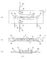
- FIG. 3 shows an example of the capillary electrophoresis apparatus according to the present invention.
- FIG. 3(A) is a plan view of the capillary electrophoresis apparatus of this example
- FIG. 3(B) is a sectional view taken on line I-I shown in FIG. 3(A)
- FIG. 3(C) is a sectional view taken on line II-II shown in FIG. 3(A) .
- the capillary electrophoresis apparatus of this example is a microchip electrophoresis apparatus with a reduced size (formed into a microchip).
- this microchip electrophoresis apparatus includes a substrate 1, a plurality (four in this example) of liquid reservoirs 2a to 2d, and four capillary tubes 3x1, 3x2, 3y1, and 3y2. All of the four capillary tubes are capillary tubes of the present invention.
- the four liquid reservoirs 2a to 2d include a first introduction reservoir 2a, a first recovery reservoir 2b, a second introduction reservoir 2c, and a second recovery reservoir 2d.
- one ends thereof meet at the central portion c to be joined together in a cross shape. Accordingly, the four capillary tubes communicate with one another at their inner parts.
- the substrate 1 is provided with a cavity for inserting the four capillary tubes thereinto (not shown in the figures).
- the capillary tube 3x1 is inserted into the substrate 1 so that the other end thereof is located at the bottom surface of the first introduction reservoir 2a.
- the capillary tube 3x2 is inserted into the substrate 1 so that the other end thereof is located at the bottom surface of the first recovery reservoir 2b.
- the capillary tubes 3x1 and 3x2 form a capillary channel 3x for sample analysis.
- the capillary tube 3y1 is inserted into the substrate 1 so that the other end thereof is located at the bottom surface of the second introduction reservoir 2c.
- the capillary tube 3y2 is inserted into the substrate 1 so that the other end thereof is located at the bottom surface of the second recovery reservoir 2d.
- the capillary tubes 3y1 and 3y2 form a capillary channel 3y for sample introduction.
- the plurality of liquid reservoirs 2a to 2d each are formed as a concave part in the substrate 1.
- the substrate 1 has a rectangular parallelepiped opening (window) 9 on the first recovery reservoir 2b side with respect to the capillary channel 3y for sample introduction.
- the microchip electrophoresis apparatus of this example is rectangular parallelepiped. However, the present invention is not limited thereto.
- the microchip electrophoresis apparatus of the present invention may have any shape as long as it does not cause any problems in the electrophoresis measurement.
- the planar shape of the microchip electrophoresis apparatus of this example is rectangular. However, the present invention is not limited thereto.
- the planar shape of the microchip electrophoresis apparatus of the present invention may be, for example, square or another shape.
- the capillary channel 3x for sample analysis is different in maximum length from the capillary channel 3y for sample introduction.
- the present invention is not limited thereto.
- the maximum length of the capillary channel 3x for sample analysis may be identical to that of the capillary channel 3y for sample introduction.
- the configuration of the microchip electrophoresis apparatus of the present invention is not limited to this example.
- microchip electrophoresis chip may be produced by a process other than the production process described below.
- the substrate 1 to be used can be one formed of, for example, a glass or polymer material.
- the glass material include synthetic silica glass, and borosilicate glass.
- the polymer material include polymethylmethacrylate (PMMA), cycloolefin polymer (COP), polycarbonate (PC), polydimethylsiloxane (PDMS), polystyrene (PS), and polylactic acid.
- the maximum length, maximum width, and maximum thickness of the substrate 1 are as described above.
- the inner diameters of the four capillary tubes are the same as that of the capillary tube of the present invention.
- the capillary channel 3x for sample analysis and the capillary channel 3y for sample introduction each have a maximum length, for example, in the range of 0.5 to 15 cm.
- the respective lengths of the four capillary tubes are determined according to the maximum lengths of the capillary channel 3x for sample analysis and the capillary channel 3y for sample introduction.
- the volumes of the plurality of liquid reservoirs 2a to 2d are not particularly limited.
- each of them has a volume of 1 to 1000 mm 3 , preferably in the range of 50 to 100 mm 3 .
- the shapes of the plurality of liquid reservoirs 2a to 2d are cylindrical.
- the present invention is not limited thereto.
- the shapes of the plurality of liquid reservoirs are not particularly limited as long as they do not cause any problems in introduction and recovery of the sample described later.
- each of them may have an arbitrary shape, such as a quadrangular prism shape, a quadrangular pyramidal shape, a conical shape, or a shape formed by combining them.
- the volumes and shapes of the plurality of liquid reservoirs may be identical to or different from one another.
- microchip electrophoresis apparatus An example of the process of producing a microchip electrophoresis apparatus of this example is described below.
- the microchip electrophoresis apparatus may be produced by a process other than the production process described below.
- the substrate 1 is produced.
- the methods of forming the four liquid reservoirs 2a to 2d and the opening (window) 9 in the substrate 1 are not particularly limited.
- the formation method can be, for instance, ultrasonic machining.
- the formation method can be, for instance, a cutting method or a molding method such as injection molding, cast molding, or press molding that employs a mold.
- the four liquid reservoirs 2a to 2d and the opening (window) 9 each may be formed independently, or all of them may be formed simultaneously.
- the four liquid reservoirs 2a to 2d and the opening (window) 9 each are formed independently, they may be formed in any order. It is preferable that all the four liquid reservoirs 2a to 2d and the opening (window) 9 be formed simultaneously by, for example, a method that employs a mold, since the number of the steps is smaller in this case.
- the microchip electrophoresis apparatus further may include a plurality of electrodes.
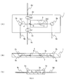
- FIG. 4 shows a microchip electrophoresis apparatus of this example that includes the plurality of electrodes.
- this microchip electrophoresis apparatus has four electrodes 6a to 6d.
- the four electrodes 6a to 6d are buried in the substrate 1 in such a manner that one ends thereof are located inside the plurality of liquid reservoirs 2a to 2d, respectively.
- the four electrodes 6a to 6d can be disposed easily when, for example, holes for introducing the four electrodes 6a to 6d are formed in the side faces of the substrate 1 in producing the substrate 1.
- the plurality of electrodes are optional components.
- the plurality of electrodes may be inserted into the plurality of liquid reservoirs when the microchip electrophoresis apparatus is used.
- the plurality of electrodes 6a to 6d may be any electrodes, as long as they can be used for the electrophoresis method.
- the plurality of electrodes 6a to 6d each are, for example, an electrode made of stainless steel (SUS), a platinum (Pt) electrode, or a gold (Au) electrode.
- the microchip electrophoresis apparatus further may include a pretreatment reservoir for hemolyzing a sample containing hemoglobin and diluting it.
- the treatment for hemolyzing the hemoglobin-containing sample is not particularly limited.
- it may be a treatment for hemolyzing the hemoglobin-containing sample with a hemolytic agent.
- the hemolytic agent destroys, for example, a blood cell membrane of a blood cell component in the hemoglobin-containing sample.
- the hemolytic agent include the aforementioned running buffer, saponin, and "Triton X-100" (trade name) manufactured by Nacalai Tesque, Inc. Particularly preferable is the running buffer.
- the pretreatment reservoir communicates with, for example, the introduction reservoirs.
- the pretreatment reservoir may be formed in a suitable place such as a place near the liquid reservoir with which it communicates, for example, the second introduction reservoir 2c.
- the pretreatment reservoir When the pretreatment reservoir is provided, the hemoglobin-containing sample is introduced into the pretreatment reservoir.
- the hemoglobin-containing sample thus pretreated is introduced into a liquid reservoir that communicates with the pretreatment reservoir, for example, the second introduction reservoir 2c through the channel connecting the pretreatment reservoir and the second introduction reservoir 2c.
- the pretreatment reservoir may have a configuration in which two reservoirs, a reservoir for hemolyzing the hemoglobin-containing sample and a reservoir for diluting the hemoglobin-containing sample, are in communication with each other.
- the microchip electrophoresis apparatus further may include an analysis unit.
- FIG. 5 shows a microchip electrophoresis apparatus of this example including the analysis unit. In FIG. 5 , identical parts to those shown in FIGs. 3 and 4 are indicated with identical numerals and symbols.
- this microchip electrophoresis apparatus includes an analysis unit 7.
- the analysis unit 7 is a detector (line detector). The line detector is disposed directly on the capillary tube 3x2 in such a manner that it is located on the first recovery reservoir 2b side with respect to the intersection part between the capillary channel 3x for sample analysis and the capillary channel 3y for sample introduction.
- the substrate 1 is provided with a cavity into which the analysis unit (line detector) 7 is to be inserted, in addition to the cavity into which the four capillary tubes are to be inserted (not shown in the figures).
- the line detector has a light source and a detection unit built-in. The line detector emits light from the light source towards the sample to detect light reflected from the sample in the detection unit, and thereby measures absorbance.
- the analysis unit 7 is not limited to the line detector. It may be any analysis unit as long as, for example, it can analyze a sample containing hemoglobin.
- the analysis unit 7 may be configured with a light source disposed under the microchip electrophoresis apparatus and a detection unit disposed in a place corresponding to the place where the line detector is disposed. In this case, light is emitted from the light source toward the sample, the transmitted light from the sample is detected in the detection unit, and thus absorbance is measured.
- FIG. 6 shows still another example of the microchip electrophoresis apparatus according to the present invention.
- identical parts to those shown in FIG. 5 are indicated with identical numerals and symbols.
- the microchip electrophoresis apparatus of this example has the same configuration as that of the microchip electrophoresis apparatus shown in FIG. 5 except that the analysis unit 7 is different.
- the analysis unit 7 may measure the absorbance at one point.
- the analytical processes of the present invention using the microchip electrophoresis apparatuses shown in FIGs. 5 and 6 can be carried out with respect to, for example, a sample containing hemoglobin, as follows.
- distilled water is passed through the capillary channel 3x for sample analysis and the capillary channel 3y for sample introduction to wash them.
- the time over which the distilled water is passed therethrough and the pressure applied when it is passed therethrough are, for example, as described above.
- a running buffer containing an anionic group-containing polysaccharide such as chondroitin sulfate is passed through the capillary channel 3x for sample analysis and the capillary channel 3y for sample introduction under pressure applied with, for example, a pump.
- the time over which it is passed therethrough and the pressure thereof are, for example, as described above.
- the capillary channel 3x for sample analysis and the capillary channel 3y for sample introduction are filled with the running buffer by pressure or capillary action.
- the step of filling them with the running buffer be completed beforehand, since it makes it possible to omit the respective steps described above and to proceed directly to the following step.
- a hemoglobin-containing sample is introduced into the second introduction reservoir 2c.
- the hemoglobin-containing sample are as described above.
- the microchip electrophoresis apparatus has the pretreatment reservoir (not shown in the figures)
- the hemoglobin-containing sample is introduced into the pretreatment reservoir and is pretreated there.
- voltage is applied to the electrode 6c and the electrode 6d to generate a potential difference between the ends of the capillary channel 3y for sample introduction.
- the hemoglobin-containing sample is introduced into the capillary channel 3y for sample introduction.
- the hemoglobin thus introduced is bonded with an anionic group-containing polysaccharide contained in the running buffer to form a complex.
- Voltage is applied to generate an electroosmotic flow in the running buffer contained in the capillary channel 3y for sample introduction and thereby the complex is transferred to the intersection part between the capillary channel 3x for sample analysis and the capillary channel 3y for sample introduction.
- the potential difference between the electrode 6c and the electrode 6d is, for instance, in the range of 0.5 to 5 kV
- the potential difference between the electrode 6a and the electrode 6b is, for example, in the range of 0.5 to 5 kV.
- the respective components of the hemoglobin-containing sample separated due to the difference in transfer rate are detected with the detector 7.
- the respective components of the hemoglobin-containing sample can be separated to be analyzed.
- a capillary tube (with an overall length of 32 cm, an effective length of 8.5 cm, and an inner diameter of 50 ⁇ m) made of fused silica was prepared.
- the capillary tube had an anionic layer formed with a silylation agent having a sulfone group that was fixed to the inner wall thereof by a covalent bond.
- Distilled water was passed through this capillary tube at a pressure of 0.1 MPa (1000 mbar) for 20 minutes to wash it.
- a running buffer (pH 5.5) was prepared that contains chondroitin sulfate added to 100 mM malic acid and an arginine acid aqueous solution at a ratio of 0.5 wt%.
- This running buffer was passed through the capillary tube at the same pressure as described above.
- a sample containing hemoglobin dissolved in distilled water was injected into the capillary tube.
- a voltage of 10 kV was applied across both ends of the capillary tube, and thereby electrophoresis was carried out.
- the hemoglobin-containing sample was injected into the capillary tube from the anode side thereof.
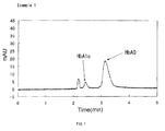
- the hemoglobin that had been transferred was detected at an absorbance of 415 nm. This result is shown in the electropherogram in FIG. 1 . As shown in FIG.
- HbA0 normal hemoglobin
- HbA1c glycated hemoglobin
- Hemoglobin was analyzed by capillary electrophoresis carried out in the same manner as in Example 1 except that a capillary tube (with an overall length of 32 cm, an effective length of 8.5 cm, and an inner diameter of 50 ⁇ m) made of fused silica that had an anionic layer formed with a silylation agent having a carboxyl group that was fixed to the inner wall thereof by a covalent bond.
- a capillary tube with an overall length of 32 cm, an effective length of 8.5 cm, and an inner diameter of 50 ⁇ m
- fused silica that had an anionic layer formed with a silylation agent having a carboxyl group that was fixed to the inner wall thereof by a covalent bond.
- FIG. 2 As shown in FIG. 2 , in this example, it was possible to detect normal hemoglobin (HbA0) and glycated hemoglobin (HbA1c) separately.
- the capillary tube used in this example allowed the analysis to be carried out immediately after being washe
- a sample such as hemoglobin can be analyzed easily with high precision by the capillary electrophoresis method. Moreover, since the present invention employs the capillary electrophoresis method, it also is possible to reduce the size of the analysis apparatus.
- the present invention is applicable to all the fields where a sample such as hemoglobin is to be analyzed, such as laboratory tests, biochemical examinations, and medical research. The intended use thereof is not limited and it is applicable to a wide range of fields.
Landscapes
- Health & Medical Sciences (AREA)
- Life Sciences & Earth Sciences (AREA)
- Molecular Biology (AREA)
- Chemical & Material Sciences (AREA)
- Chemical Kinetics & Catalysis (AREA)
- Electrochemistry (AREA)
- Physics & Mathematics (AREA)
- Analytical Chemistry (AREA)
- Biochemistry (AREA)
- General Health & Medical Sciences (AREA)
- General Physics & Mathematics (AREA)
- Immunology (AREA)
- Pathology (AREA)
- Investigating Or Analysing Biological Materials (AREA)
Abstract
Description
- The present invention relates to a process for analyzing a sample by a capillary electrophoresis method as well as a capillary tube and a capillary electrophoresis apparatus that are used for the process.
- In the capillary electrophoresis method, ions that have gathered on the inner wall of a capillary tube are transferred upon voltage application to generate an electroosmotic flow, which transfers the sample, and thus electrophoresis is performed. For the capillary tube, one made of fused silica is used. In this case, however, adsorption of the sample may prevent a good electroosmotic flow from being obtained. Accordingly, techniques of coating the inner walls of capillary tubes have been proposed (
Patent Documents - However, there is a problem in that the aforementioned conventional capillary electrophoresis method does not allow hemoglobin to be analyzed with high precision. In order to solve this problem, there is a technique in which the inner wall of a capillary tube is coated with a protein, which then is coated with polysaccharide (Patent Document 5). However, in this technique, an operation is required in which the inner wall of a capillary tube is coated with a protein each time the analysis is carried out, and therefore there is a problem in that the analysis becomes complicated. On the other hand, there is a method in which capillary electrophoresis is carried out with a zwitterionic type of running buffer that is allowed to contain a flow inhibitor such as aliphatic diamine, with the inner wall of the capillary tube not being coated (Patent Document 6). However, there is a problem in that this method allows variant hemoglobin to be separated but does not allow hemoglobin A1c to be separated. These problems apply to the general capillary electrophoresis method with respect to not only hemoglobin but also other samples.
- [Patent Document 1]
JP 2005-291920 A - [Patent Document 2]
JP4(1992)-320957 A - [Patent Document 3]
JP 5(1993)-503989 A - [Patent Document 4]
JP 8(1996)-504037 A - [Patent Document 5]
JP 9(1997)-105739 A - [Patent Document 6]
JP2006-145537 A - Accordingly, the present invention is intended to provide a process for analyzing a sample by a capillary electrophoresis method that allows the apparatus to be reduced in size, allows a high analytical precision to be obtained, and can be carried out easily, as well as a capillary tube and a capillary electrophoresis apparatus that are used for the process.
- In order to achieve the aforementioned object, an analytical process of the present invention is a process for analyzing a sample by a capillary electrophoresis method. The process includes a step of preparing a capillary tube to be used for the capillary electrophoresis method, and a step of electrophoresing a complex of a sample and an anionic group-containing compound that are bonded together, in the capillary tube, wherein the capillary tube includes an anionic layer that is formed of the anionic group-containing compound and that is coated on an inner wall of the capillary tube, and the anionic layer is fixed to the inner wall of the capillary tube by a covalent bond.
- A capillary tube of the present invention is a capillary tube for capillary electrophoresis to be used for the analytical process of the present invention, wherein an anionic layer formed of an anionic group-containing compound is coated on an inner wall of the capillary tube, and the anionic layer is fixed to the inner wall of the capillary tube by a covalent bond.
- A capillary electrophoresis apparatus of the present invention is a capillary electrophoresis apparatus to be used for the analytical process of the present invention, wherein the capillary tube of the present invention is included. The capillary electrophoresis apparatus of the present invention may be a microchip electrophoresis apparatus with a reduced size (formed into a microchip) as described later.
- In the analytical process of the present invention, the use of a capillary tube including an anionic layer fixed to the inner wall of the capillary tube by a covalent bond can prevent, for example, a protein in a blood sample, such as hemoglobin, from being adsorbed by the inner wall of the capillary tube. This makes it possible to generate a good electroosmotic flow. Furthermore, in the analytical process of the present invention, since a complex is generated by bonding a sample and an anionic group-containing compound, which then is performed electrophoretic separation, a higher separation efficiency is obtained as compared to the case where the sample alone is performed electrophoretic separation. Thus, according to the analytical process of the present invention, a sample such as hemoglobin can be analyzed in a short time with high precision. Moreover, since the anionic layer is fixed firmly to the inner wall of the capillary tube, once it is formed, it is not separated therefrom easily, even when being washed, which allows it to be used repeatedly. Accordingly, in the analytical process of the present invention, once the anionic layer is formed, it is not necessary to form the anionic layer every time an analysis is carried out, and thereby the analysis can be carried out easily. Furthermore, in the present invention, since the capillary electrophoresis method is employed, it is possible to reduce the size of the analysis apparatus.
-
-
FIG. 1 is an electropherogram showing the result of analysis of hemoglobin in an example of the present invention. -
FIG. 2 is an electropherogram showing the result of analysis of hemoglobin in another example of the present invention. -
FIG. 3 shows diagrams illustrating the configuration of an example of the capillary electrophoresis apparatus of the present invention.FIG. 3(A) is a plan view of the capillary electrophoresis apparatus of this example,FIG. 3(B) is a sectional view taken on line I-I shown inFIG. 3(A), and FIG. 3(C) is a sectional view taken on line II-II shown inFIG. 3(A) . -
FIG. 4 shows diagrams illustrating the configuration of another example of the capillary electrophoresis apparatus of the present invention. -
FIG. 5 shows diagrams illustrating the configuration of still another example of the capillary electrophoresis apparatus of the present invention. -
FIG. 6 shows diagrams illustrating the configuration of yet another example of the capillary electrophoresis apparatus of the present invention. - In the present invention, the term "running buffer" denotes a buffer solution (buffer) that is used in an actual separation process. Preferably, in the capillary tube to be used in the analytical process of the present invention, a sample is introduced into a running buffer containing an anionic group-containing compound, and voltage then is applied across both ends of the capillary tube to perform electrophoretic separation of a complex of the sample and the anionic group-containing compound.
- In the analytical process and the capillary tube of the present invention, a preferable anionic group-containing compound that forms the complex together with the sample is an anionic group-containing polysaccharide. Examples of the anionic group-containing polysaccharide include sulfated polysaccharide, carboxylated polysaccharide, sulfonated polysaccharide, and phosphorylated polysaccharide. Particularly, sulfated polysaccharide and carboxylated polysaccharide are preferable. The sulfated polysaccharide is preferably, for example, chondroitin sulfate or heparin, more preferably chondroitin sulfate. The carboxylated polysaccharide is preferably alginic acid or a salt thereof (for instance, sodium alginate). There are seven types of chondroitin sulfates A, B, C, D, E, H, and K and any of them may be used.
- In the analytical process and the anionic group-containing compound that forms the anionic layer of the capillary tube of the present invention, the anionic group is preferably at least one of a sulfone group and a carboxyl group.
- In the present invention, it is preferable that the sample contains hemoglobin.
- The capillary electrophoresis apparatus of the present invention may include a substrate, a plurality of liquid reservoirs, and a capillary tube, wherein the plurality of liquid reservoirs may be formed in the substrate and may be allowed to communicate with one another through the capillary tube, and the capillary tube may be the capillary tube of the present invention. In this case, the substrate has a maximum length, for example, in the range of 10 to 100 mm, preferably in the range of 30 to 70 mm, a maximum width, for instance, in the range of 10 to 60 mm, and a maximum thickness, for example, in the range of 0.3 to 5 mm. The maximum length of the substrate is the length of the portion that is longest in the longitudinal direction of the substrate. The maximum width of the substrate is the length of the portion that is longest in the direction (width direction) perpendicular to the longitudinal direction of the substrate. The maximum thickness of the substrate is the length of the portion that is longest in the direction (thickness direction) perpendicular to both the longitudinal direction and the width direction of the substrate. As described above, the capillary electrophoresis apparatus of the present invention may be a microchip electrophoresis apparatus with a reduced size (formed into a microchip).
- Next, the present invention is described in detail.
- As described above, the capillary tube of the present invention is provided with an anionic layer formed on the inner wall thereof.
- The material for the capillary tube is not particularly limited. Examples thereof include glass, fused silica, and plastic. The inner wall of a capillary tube made of glass or fused silica usually has negative electric charges. The inner wall of a capillary tube made of plastic has positive or negative electric charges depending on the presence or absence and the type of the polar group contained in the plastic or is uncharged (nonpolar). Even in the case of plastic having no polar group, introduction of a polar group allows it to have electric charges. A commercial product may be used as the capillary tube made of plastic. Examples of the capillary tube include those formed of, for example, polymethylmethacrylate, polycarbonate, polystyrene, polyethylene, polytetrafluoroethylene (PTFE), and polyether ether ketone (PEEK). The inner diameter of the capillary tube is, for example, in the range of 10 to 200 µm, preferably in the range of 25 to 100 µm. The length of the capillary tube is, for example, in the range of 10 to 1000 mm.
- For the formation of the anionic layer on the inner wall of the capillary tube with the anionic group-containing compound, for example, a compound containing the anionic group and a reactive group may be used. When the capillary tube is made of glass or fused silica, a compound containing an anionic group and silicon (a silylation agent) can be used. As described above, the anionic group is preferably at least one of a sulfone group and a carboxyl group.
- Examples of the silylation agent include 2-(4-chlorosulfonylphenyl)ethyltrimethoxysilane, and 2-(4-chlorosulfonylphenyl)ethyltrichlorosilane.
- For the silylation agent, one obtained by substituting the silicon atom with titanium or zirconium may be used. One silylation agent may be used alone or two or more of them may be used in combination.
- The anionic layer is formed using the silylation agent, for example, as follows. First, a silylation agent is dissolved or dispersed in an organic solvent and thereby a treatment liquid is prepared. The organic solvent to be used for preparing the treatment liquid can be, for example, dichloromethane or toluene. The concentration of the silylation agent of the treatment liquid is not particularly limited. This treatment liquid is passed through a capillary tube made of glass or fused silica and is heated. This heating allows the silylation agent to be bonded to the inner wall of the capillary tube by a covalent bond. As a result, the anionic group is placed on the inner wall of the capillary tube. Thereafter, it is washed with at least one of an organic solvent (for instance, dichloromethane, methanol, or acetone), an acid solution (for example, phosphoric acid), an alkaline solution, and a surfactant solution (aftertreatment). Preferably, this washing is carried out, although it is optional. A commercial product may be used as the capillary tube having an anionic layer formed with the silylation agent.
- The running buffer is not particularly limited, but a buffer containing acid used therein is preferred. Examples of the acid include maleic acid, tartaric acid, succinic acid, fumaric acid, phthalic acid, malonic acid, and malic acid. Preferably, the running buffer contains a weak base. Examples of the weak base include arginine, lysine, histidine, and tris. The running buffer has a pH, for example, in the range of 4.5 to 6. The types of the buffer of the running buffer include MES, ADA, ACES, BES, MOPS, TES, and HEPES. In the running buffer, the anionic group-containing compound that forms a complex together with the sample has a concentration, for example, in the range of 0.01 to 5 wt%.
- The analytical process of the present invention can be carried out with respect to, for example, a sample containing hemoglobin as follows.
- First, a capillary tube made of glass or fused silica is prepared. An anionic group-containing compound has been fixed to the inner wall of the capillary tube by a covalent bond. Distilled water is passed through the capillary tube and thereby it is washed. The time over which the distilled water is passed therethrough is, for example, 1 to 10 minutes, and the pressure applied when the distilled water is passed therethrough is, for example, 0.05 to 0.1 MPa. Subsequently, a running buffer containing an anionic group-containing polysaccharide such as chondroitin sulfate is passed through the capillary tube under pressure applied with, for example, a pump. The time over which it is passed therethrough is, for example, 10 to 60 minutes and the pressure applied when it is passed therethrough is, for example, 0.05 to 0.1 MPa. With the capillary tube being filled with the running buffer, a hemoglobin-containing sample is introduced into the capillary tube, and voltage then is applied across both the ends of the capillary tube to carry out electrophoresis. The hemoglobin-containing sample is not particularly limited and is, for example, a sample obtained by hemolyzing whole blood. This sample may be diluted with distilled water or a running buffer. The hemoglobin-containing sample is introduced from the anode side of the capillary tube. The hemoglobin thus introduced forms a complex by being bonded with the anionic group-containing polysaccharide contained in the running buffer. Voltage application generates an electroosmotic flow in the running buffer contained in the capillary tube and thereby the complex is transferred toward the cathode side of the capillary tube. The voltage applied is, for example, in the order of 10 to 30 kV. This transfer is detected by an optical method. The detection made by the optical method is not particularly limited. Preferably, it is carried out with a wavelength of 415 nm.
- In the present invention, the hemoglobin to be analyzed is not particularly limited. Examples thereof include normal hemoglobin, glycated hemoglobin (for instance, HbA1c, labile HbA1c, and GHbLys), and hemoglobin variants. In the present invention, it is possible to separate HbA1c and hemoglobin other than that from each other to analyze them.
- Next, the capillary electrophoresis apparatus of the present invention is described using examples. However, the capillary electrophoresis apparatus of the present invention is not limited to the following examples.
-
FIG. 3 shows an example of the capillary electrophoresis apparatus according to the present invention.FIG. 3(A) is a plan view of the capillary electrophoresis apparatus of this example,FIG. 3(B) is a sectional view taken on line I-I shown inFIG. 3(A), and FIG. 3(C) is a sectional view taken on line II-II shown inFIG. 3(A) . In those figures, for ease of understanding, for example, the sizes and ratios of the respective components are different from actual ones. The capillary electrophoresis apparatus of this example is a microchip electrophoresis apparatus with a reduced size (formed into a microchip). As shown in the figures, this microchip electrophoresis apparatus includes asubstrate 1, a plurality (four in this example) ofliquid reservoirs 2a to 2d, and four capillary tubes 3x1, 3x2, 3y1, and 3y2. All of the four capillary tubes are capillary tubes of the present invention. The fourliquid reservoirs 2a to 2d include afirst introduction reservoir 2a, afirst recovery reservoir 2b, asecond introduction reservoir 2c, and asecond recovery reservoir 2d. In the four capillary tubes, one ends thereof meet at the central portion c to be joined together in a cross shape. Accordingly, the four capillary tubes communicate with one another at their inner parts. Thesubstrate 1 is provided with a cavity for inserting the four capillary tubes thereinto (not shown in the figures). The capillary tube 3x1 is inserted into thesubstrate 1 so that the other end thereof is located at the bottom surface of thefirst introduction reservoir 2a. The capillary tube 3x2 is inserted into thesubstrate 1 so that the other end thereof is located at the bottom surface of thefirst recovery reservoir 2b. The capillary tubes 3x1 and 3x2 form acapillary channel 3x for sample analysis. The capillary tube 3y1 is inserted into thesubstrate 1 so that the other end thereof is located at the bottom surface of thesecond introduction reservoir 2c. The capillary tube 3y2 is inserted into thesubstrate 1 so that the other end thereof is located at the bottom surface of thesecond recovery reservoir 2d. The capillary tubes 3y1 and 3y2 form acapillary channel 3y for sample introduction. The plurality ofliquid reservoirs 2a to 2d each are formed as a concave part in thesubstrate 1. Thesubstrate 1 has a rectangular parallelepiped opening (window) 9 on thefirst recovery reservoir 2b side with respect to thecapillary channel 3y for sample introduction. The microchip electrophoresis apparatus of this example is rectangular parallelepiped. However, the present invention is not limited thereto. The microchip electrophoresis apparatus of the present invention may have any shape as long as it does not cause any problems in the electrophoresis measurement. The planar shape of the microchip electrophoresis apparatus of this example is rectangular. However, the present invention is not limited thereto. The planar shape of the microchip electrophoresis apparatus of the present invention may be, for example, square or another shape. In the microchip electrophoresis apparatus of this example, thecapillary channel 3x for sample analysis is different in maximum length from thecapillary channel 3y for sample introduction. However, the present invention is not limited thereto. In the microchip electrophoresis apparatus of the present invention, the maximum length of thecapillary channel 3x for sample analysis may be identical to that of thecapillary channel 3y for sample introduction. Similarly with respect to items other than those described above, the configuration of the microchip electrophoresis apparatus of the present invention is not limited to this example. - Next, the process for producing the microchip electrophoresis apparatus of this example is described. However, the microchip electrophoresis chip may be produced by a process other than the production process described below.
- In the microchip electrophoresis apparatus of this example, the
substrate 1 to be used can be one formed of, for example, a glass or polymer material. Examples of the glass material include synthetic silica glass, and borosilicate glass. Examples of the polymer material include polymethylmethacrylate (PMMA), cycloolefin polymer (COP), polycarbonate (PC), polydimethylsiloxane (PDMS), polystyrene (PS), and polylactic acid. - In the microchip electrophoresis apparatus of this example, the maximum length, maximum width, and maximum thickness of the
substrate 1 are as described above. - The inner diameters of the four capillary tubes are the same as that of the capillary tube of the present invention. The
capillary channel 3x for sample analysis and thecapillary channel 3y for sample introduction each have a maximum length, for example, in the range of 0.5 to 15 cm. The respective lengths of the four capillary tubes are determined according to the maximum lengths of thecapillary channel 3x for sample analysis and thecapillary channel 3y for sample introduction. - The volumes of the plurality of
liquid reservoirs 2a to 2d are not particularly limited. For example, each of them has a volume of 1 to 1000 mm3, preferably in the range of 50 to 100 mm3. InFIG. 3 , the shapes of the plurality ofliquid reservoirs 2a to 2d are cylindrical. However, the present invention is not limited thereto. In the microchip electrophoresis apparatus of the present invention, the shapes of the plurality of liquid reservoirs are not particularly limited as long as they do not cause any problems in introduction and recovery of the sample described later. For example, each of them may have an arbitrary shape, such as a quadrangular prism shape, a quadrangular pyramidal shape, a conical shape, or a shape formed by combining them. Furthermore, the volumes and shapes of the plurality of liquid reservoirs may be identical to or different from one another. - An example of the process of producing a microchip electrophoresis apparatus of this example is described below. However, the microchip electrophoresis apparatus may be produced by a process other than the production process described below.
- First, the
substrate 1 is produced. The methods of forming the fourliquid reservoirs 2a to 2d and the opening (window) 9 in thesubstrate 1 are not particularly limited. For example, when the material used for thesubstrate 1 is the aforementioned glass, the formation method can be, for instance, ultrasonic machining. For example, when the material used for thesubstrate 1 is the aforementioned polymer material, the formation method can be, for instance, a cutting method or a molding method such as injection molding, cast molding, or press molding that employs a mold. The fourliquid reservoirs 2a to 2d and the opening (window) 9 each may be formed independently, or all of them may be formed simultaneously. When the fourliquid reservoirs 2a to 2d and the opening (window) 9 each are formed independently, they may be formed in any order. It is preferable that all the fourliquid reservoirs 2a to 2d and the opening (window) 9 be formed simultaneously by, for example, a method that employs a mold, since the number of the steps is smaller in this case. - Next, the four capillary tubes are inserted into the
substrate 1. Thus, a microchip electrophoresis apparatus of this example can be obtained. - The microchip electrophoresis apparatus further may include a plurality of electrodes.
FIG. 4 shows a microchip electrophoresis apparatus of this example that includes the plurality of electrodes. InFIG. 4 , the identical parts to those shown inFIG. 3 are indicated with identical numerals and symbols. As shown inFIG. 4 , this microchip electrophoresis apparatus has fourelectrodes 6a to 6d. The fourelectrodes 6a to 6d are buried in thesubstrate 1 in such a manner that one ends thereof are located inside the plurality ofliquid reservoirs 2a to 2d, respectively. The fourelectrodes 6a to 6d can be disposed easily when, for example, holes for introducing the fourelectrodes 6a to 6d are formed in the side faces of thesubstrate 1 in producing thesubstrate 1. In the microchip electrophoresis apparatus, the plurality of electrodes are optional components. For example, the plurality of electrodes may be inserted into the plurality of liquid reservoirs when the microchip electrophoresis apparatus is used. - The plurality of
electrodes 6a to 6d may be any electrodes, as long as they can be used for the electrophoresis method. The plurality ofelectrodes 6a to 6d each are, for example, an electrode made of stainless steel (SUS), a platinum (Pt) electrode, or a gold (Au) electrode. - The microchip electrophoresis apparatus further may include a pretreatment reservoir for hemolyzing a sample containing hemoglobin and diluting it. The treatment for hemolyzing the hemoglobin-containing sample is not particularly limited. For example, it may be a treatment for hemolyzing the hemoglobin-containing sample with a hemolytic agent. The hemolytic agent destroys, for example, a blood cell membrane of a blood cell component in the hemoglobin-containing sample. Examples of the hemolytic agent include the aforementioned running buffer, saponin, and "Triton X-100" (trade name) manufactured by Nacalai Tesque, Inc. Particularly preferable is the running buffer. Preferably, the pretreatment reservoir communicates with, for example, the introduction reservoirs. The pretreatment reservoir may be formed in a suitable place such as a place near the liquid reservoir with which it communicates, for example, the
second introduction reservoir 2c. When the pretreatment reservoir is provided, the hemoglobin-containing sample is introduced into the pretreatment reservoir. The hemoglobin-containing sample thus pretreated is introduced into a liquid reservoir that communicates with the pretreatment reservoir, for example, thesecond introduction reservoir 2c through the channel connecting the pretreatment reservoir and thesecond introduction reservoir 2c. The pretreatment reservoir may have a configuration in which two reservoirs, a reservoir for hemolyzing the hemoglobin-containing sample and a reservoir for diluting the hemoglobin-containing sample, are in communication with each other. - The microchip electrophoresis apparatus further may include an analysis unit.
FIG. 5 shows a microchip electrophoresis apparatus of this example including the analysis unit. InFIG. 5 , identical parts to those shown inFIGs. 3 and4 are indicated with identical numerals and symbols. As shown inFIG. 5 , this microchip electrophoresis apparatus includes ananalysis unit 7. In the microchip electrophoresis apparatus of this example, theanalysis unit 7 is a detector (line detector). The line detector is disposed directly on the capillary tube 3x2 in such a manner that it is located on thefirst recovery reservoir 2b side with respect to the intersection part between thecapillary channel 3x for sample analysis and thecapillary channel 3y for sample introduction. In this microchip electrophoresis apparatus, thesubstrate 1 is provided with a cavity into which the analysis unit (line detector) 7 is to be inserted, in addition to the cavity into which the four capillary tubes are to be inserted (not shown in the figures). The line detector has a light source and a detection unit built-in. The line detector emits light from the light source towards the sample to detect light reflected from the sample in the detection unit, and thereby measures absorbance. Theanalysis unit 7 is not limited to the line detector. It may be any analysis unit as long as, for example, it can analyze a sample containing hemoglobin. For example, theanalysis unit 7 may be configured with a light source disposed under the microchip electrophoresis apparatus and a detection unit disposed in a place corresponding to the place where the line detector is disposed. In this case, light is emitted from the light source toward the sample, the transmitted light from the sample is detected in the detection unit, and thus absorbance is measured. -
FIG. 6 shows still another example of the microchip electrophoresis apparatus according to the present invention. InFIG. 6 , identical parts to those shown inFIG. 5 are indicated with identical numerals and symbols. As shown inFIG. 6 , the microchip electrophoresis apparatus of this example has the same configuration as that of the microchip electrophoresis apparatus shown inFIG. 5 except that theanalysis unit 7 is different. As in this example, theanalysis unit 7 may measure the absorbance at one point. - The analytical processes of the present invention using the microchip electrophoresis apparatuses shown in
FIGs. 5 and6 can be carried out with respect to, for example, a sample containing hemoglobin, as follows. - First, distilled water is passed through the
capillary channel 3x for sample analysis and thecapillary channel 3y for sample introduction to wash them. The time over which the distilled water is passed therethrough and the pressure applied when it is passed therethrough are, for example, as described above. Subsequently, a running buffer containing an anionic group-containing polysaccharide such as chondroitin sulfate is passed through thecapillary channel 3x for sample analysis and thecapillary channel 3y for sample introduction under pressure applied with, for example, a pump. The time over which it is passed therethrough and the pressure thereof are, for example, as described above. Thereafter, thecapillary channel 3x for sample analysis and thecapillary channel 3y for sample introduction are filled with the running buffer by pressure or capillary action. - It is preferable that when the microchip electrophoresis apparatus is not in use (when no analysis is carried out), the step of filling them with the running buffer be completed beforehand, since it makes it possible to omit the respective steps described above and to proceed directly to the following step.
- Subsequently, a hemoglobin-containing sample is introduced into the
second introduction reservoir 2c. Examples of the hemoglobin-containing sample are as described above. When the microchip electrophoresis apparatus has the pretreatment reservoir (not shown in the figures), the hemoglobin-containing sample is introduced into the pretreatment reservoir and is pretreated there. Subsequently, voltage is applied to theelectrode 6c and theelectrode 6d to generate a potential difference between the ends of thecapillary channel 3y for sample introduction. Thus, the hemoglobin-containing sample is introduced into thecapillary channel 3y for sample introduction. The hemoglobin thus introduced is bonded with an anionic group-containing polysaccharide contained in the running buffer to form a complex. Voltage is applied to generate an electroosmotic flow in the running buffer contained in thecapillary channel 3y for sample introduction and thereby the complex is transferred to the intersection part between thecapillary channel 3x for sample analysis and thecapillary channel 3y for sample introduction. - The potential difference between the
electrode 6c and theelectrode 6d is, for instance, in the range of 0.5 to 5 kV - Next, voltage is applied to the
electrode 6a and theelectrode 6b to generate a potential difference between the ends of thecapillary channel 3x for sample analysis. In this manner, the capillary channel having a potential difference between the ends thereof is changed momentarily from thecapillary channel 3y for sample introduction to thecapillary channel 3x for sample analysis, so that as shown with arrows inFIGs. 5 and6 , thesample 8 is transferred to thefirst recovery reservoir 2b side from the intersection part between thecapillary channel 3x for sample analysis and thecapillary channel 3y for sample introduction. - The potential difference between the
electrode 6a and theelectrode 6b is, for example, in the range of 0.5 to 5 kV. - Subsequently, the respective components of the hemoglobin-containing sample separated due to the difference in transfer rate are detected with the
detector 7. Thus, the respective components of the hemoglobin-containing sample can be separated to be analyzed. - Next, examples of the present invention are described.
- A capillary tube (with an overall length of 32 cm, an effective length of 8.5 cm, and an inner diameter of 50 µm) made of fused silica was prepared. The capillary tube had an anionic layer formed with a silylation agent having a sulfone group that was fixed to the inner wall thereof by a covalent bond. Distilled water was passed through this capillary tube at a pressure of 0.1 MPa (1000 mbar) for 20 minutes to wash it. Subsequently, a running buffer (pH 5.5) was prepared that contains chondroitin sulfate added to 100 mM malic acid and an arginine acid aqueous solution at a ratio of 0.5 wt%. This running buffer was passed through the capillary tube at the same pressure as described above. With the capillary tube being filled with the running buffer, a sample containing hemoglobin dissolved in distilled water was injected into the capillary tube. Thereafter, a voltage of 10 kV was applied across both ends of the capillary tube, and thereby electrophoresis was carried out. The hemoglobin-containing sample was injected into the capillary tube from the anode side thereof. The hemoglobin that had been transferred was detected at an absorbance of 415 nm. This result is shown in the electropherogram in
FIG. 1 . As shown inFIG. 1 , in this example, it was possible to detect normal hemoglobin (HbA0) and glycated hemoglobin (HbA1c) separately. Furthermore, the capillary tube used in this example allowed the analysis to be carried out immediately after being washed. - Hemoglobin was analyzed by capillary electrophoresis carried out in the same manner as in Example 1 except that a capillary tube (with an overall length of 32 cm, an effective length of 8.5 cm, and an inner diameter of 50 µm) made of fused silica that had an anionic layer formed with a silylation agent having a carboxyl group that was fixed to the inner wall thereof by a covalent bond. This result is shown in the electropherogram in
FIG. 2 . As shown inFIG. 2 , in this example, it was possible to detect normal hemoglobin (HbA0) and glycated hemoglobin (HbA1c) separately. Furthermore, the capillary tube used in this example allowed the analysis to be carried out immediately after being washed. - As described above, according to the present invention, a sample such as hemoglobin can be analyzed easily with high precision by the capillary electrophoresis method. Moreover, since the present invention employs the capillary electrophoresis method, it also is possible to reduce the size of the analysis apparatus. The present invention is applicable to all the fields where a sample such as hemoglobin is to be analyzed, such as laboratory tests, biochemical examinations, and medical research. The intended use thereof is not limited and it is applicable to a wide range of fields.
Claims (15)
- A process for analyzing a sample by a capillary electrophoresis method, comprising:preparing a capillary tube to be used for the capillary electrophoresis method, andperforming electrophoretic separation of a complex of a sample and an anionic group-containing compound that are bonded together, in the capillary tube,wherein the capillary tube includes an anionic layer that is formed of the anionic group-containing compound and that is coated on an inner wall of the capillary tube, and the anionic layer is fixed to the inner wall of the capillary tube by a covalent bond.
- The analytical process according to claim 1, wherein in the capillary tube, a sample is introduced into a running buffer containing the anionic group-containing compound, and then voltage is applied across both ends of the capillary tube to perform electrophoretic separation of the complex of the sample and the anionic group-containing compound.
- The analytical process according to claim 1, wherein the anionic group-containing compound that forms the complex together with the sample is an anionic group-containing polysaccharide.
- The analytical process according to claim 3, wherein the anionic group-containing polysaccharide is at least one polysaccharide selected from the group consisting of sulfated polysaccharide, carboxylated polysaccharide, sulfonated polysaccharide, and phosphorylated polysaccharide.
- The analytical process according to claim 4, wherein the sulfated polysaccharide is chondroitin sulfate.
- The analytical process according to claim 1, wherein in the anionic group-containing compound that forms the anionic layer, the anionic group is at least one of a sulfone group and a carboxyl group.
- The analytical process according to claim 1, wherein the sample contains hemoglobin.
- A capillary tube for capillary electrophoresis to be used for an analytical process according to claim 1, wherein an anionic layer formed of an anionic group-containing compound is coated on an inner wall of the capillary tube, and the anionic layer is fixed to the inner wall of the capillary tube by a covalent bond.
- The capillary tube according to claim 8, wherein the anionic group-containing compound that forms a complex together with the sample is an anionic group-containing polysaccharide.
- The capillary tube according to claim 9, wherein the anionic group-containing polysaccharide is at least one polysaccharide selected from the group consisting of sulfated polysaccharide, carboxylated polysaccharide, sulfonated polysaccharide, and phosphorylated polysaccharide.
- The capillary tube according to claim 10, wherein the sulfated polysaccharide is chondroitin sulfate.
- The capillary tube according to claim 8, wherein in the anionic group-containing compound that forms the anionic layer, the anionic group is at least one of a sulfone group and a carboxyl group.
- A capillary electrophoresis apparatus to be used for an analytical process according to claim 1, comprising a capillary tube according to claim 8.
- The capillary electrophoresis apparatus according to claim 13,
wherein the capillary electrophoresis apparatus comprises a substrate, a plurality of liquid reservoirs, and a capillary tube, the plurality of liquid reservoirs are formed in the substrate, the plurality of liquid reservoirs are allowed to communicate with each other through the capillary tube, and the capillary tube is a capillary tube according to claim 8. - The capillary electrophoresis apparatus according to claim 14,
wherein the substrate has a maximum length in a range of 10 to 100 mm, a maximum width in a range of 10 to 60 mm, and a maximum thickness in a range of 0.3 to 5 mm.
Applications Claiming Priority (2)
| Application Number | Priority Date | Filing Date | Title |
|---|---|---|---|
| JP2006239641 | 2006-09-04 | ||
| PCT/JP2007/066752 WO2008029685A1 (en) | 2006-09-04 | 2007-08-29 | Method for analysis of sample by capillary electrophoresis |
Publications (3)
| Publication Number | Publication Date |
|---|---|
| EP2060913A1 true EP2060913A1 (en) | 2009-05-20 |
| EP2060913A4 EP2060913A4 (en) | 2012-04-25 |
| EP2060913B1 EP2060913B1 (en) | 2016-11-02 |
Family
ID=39157117
Family Applications (1)
| Application Number | Title | Priority Date | Filing Date |
|---|---|---|---|
| EP07806229.6A Active EP2060913B1 (en) | 2006-09-04 | 2007-08-29 | Method for analysis of sample by capillary electrophoresis |
Country Status (5)
| Country | Link |
|---|---|
| US (1) | US8137512B2 (en) |
| EP (1) | EP2060913B1 (en) |
| JP (1) | JP4814945B2 (en) |
| CN (1) | CN101501485B (en) |
| WO (1) | WO2008029685A1 (en) |
Cited By (2)
| Publication number | Priority date | Publication date | Assignee | Title |
|---|---|---|---|---|
| US8252163B2 (en) | 2008-07-22 | 2012-08-28 | Arkray, Inc. | Analysis apparatus for capillary electrophoresis |
| EP2343544B1 (en) * | 2009-12-25 | 2015-03-11 | Arkray, Inc. | Method for analyzing hemoglobin by electrophoresis |
Families Citing this family (12)
| Publication number | Priority date | Publication date | Assignee | Title |
|---|---|---|---|---|
| US20100051464A1 (en) * | 2007-04-27 | 2010-03-04 | Arkray Inc. | Analysis chip and analysis apparatus |
| EP2144056A4 (en) * | 2007-04-27 | 2010-10-27 | Arkray Inc | Electrophoresis chip and electrophoresis apparatus |
| CN102047104B (en) * | 2008-07-22 | 2014-09-03 | 爱科来株式会社 | Analysis device and analysis method using capillary electrophoresis |
| FR2947632B1 (en) | 2009-07-01 | 2011-11-11 | Sebia Sa | ANALYSIS AND DETERMINATION OF GLYCATED HEMOGLOBINS BY CAPILLARY ELECTROPHORESIS, BUFFER COMPOSITIONS AND KITS FOR CAPILLARY ELECTROPHORESIS |
| CN101718746B (en) * | 2009-12-30 | 2013-04-10 | 中国科学院长春应用化学研究所 | Method for detecting sarcosine |
| JP5551092B2 (en) | 2010-01-19 | 2014-07-16 | アークレイ株式会社 | Method of analyzing sample using electrophoresis and use thereof |
| JP5778547B2 (en) | 2010-10-28 | 2015-09-16 | アークレイ株式会社 | Calibration method in hemoglobin A1c measurement |
| JP5616309B2 (en) | 2010-12-01 | 2014-10-29 | アークレイ株式会社 | Device and manufacturing method thereof |
| JP5977269B2 (en) * | 2013-01-22 | 2016-08-24 | アークレイ株式会社 | Sample analysis method and solution used therefor |
| CN103691318B (en) * | 2014-01-07 | 2016-03-30 | 延边大学 | The separation method of minute yardstick material and capillary column transverse electric chromatographic separation device |
| CN108445071B (en) * | 2018-02-08 | 2021-03-30 | 中国计量科学研究院 | High-accuracy glycosylated hemoglobin standard substance valuing method |
| JP7496519B2 (en) | 2019-01-31 | 2024-06-07 | パナソニックIpマネジメント株式会社 | Conductive polymer dispersion, electrolytic capacitor, and method for producing electrolytic capacitor |
Family Cites Families (38)
| Publication number | Priority date | Publication date | Assignee | Title |
|---|---|---|---|---|
| US256232A (en) | 1882-04-11 | Air-compressor | ||
| US5015350A (en) | 1989-11-06 | 1991-05-14 | Applied Biosystems, Inc. | Flow-rate-controlled surface-charge coating for capillary electrophoresis |
| US5192406A (en) | 1991-01-09 | 1993-03-09 | Supelco | Deactivated capillary columns for use in capillary electrophoresis |
| US5292416A (en) * | 1992-11-13 | 1994-03-08 | Indiana University Foundation | Pulsed-field separation of polysaccharides in capillaries |
| US5314593A (en) * | 1993-03-18 | 1994-05-24 | Hewlett-Packard Company | Capillary tube with reversible protein interaction and method |
| US5462646A (en) | 1993-09-29 | 1995-10-31 | Beckman Instruments, Inc. | Coated capillary columns and electrophoretic separation methods for their use |
| US5605613A (en) * | 1994-01-25 | 1997-02-25 | Beckman Instruments, Inc. | Polyvinylalcohol coated capillary electrophoresis columns |
| US5431793A (en) | 1994-07-29 | 1995-07-11 | Beckman Instruments, Inc. | Quantitative analysis of glycosylated hemoglobin by immunocappillary electrophoresis |
| JPH0894578A (en) * | 1994-09-28 | 1996-04-12 | Yokogawa Analytical Syst Kk | Capillary electrophoretic device |
| US5599433A (en) * | 1995-01-17 | 1997-02-04 | Beckman Instruments, Inc. | Capillary electrophoresis of glycosylated proteins |
| WO1996023220A1 (en) | 1995-01-27 | 1996-08-01 | Northeastern University | Polyvinyl alcohol (pva) based covalently bonded stable hydrophilic coating for capillary electrophoresis |
| US5611903A (en) * | 1995-03-22 | 1997-03-18 | Analis S. A. | Capillary electrophoresis method using initialized capillary and polyanion-containing buffer and chemical kit therefor |
| JPH09143202A (en) * | 1995-09-21 | 1997-06-03 | Taiho Yakuhin Kogyo Kk | Optical resolution agent and optical resolution method |
| KR100202079B1 (en) | 1996-06-21 | 1999-06-15 | 윤종용 | Detecting and separating method of multiplex syncronous signal |
| WO1998025137A1 (en) * | 1996-12-03 | 1998-06-11 | Eisai Co., Ltd. | Capillary having coated inner wall |
| JP3355393B2 (en) | 1996-12-03 | 2002-12-09 | エーザイ株式会社 | Capillaries with coated inner walls |
| JP3429709B2 (en) | 1998-08-07 | 2003-07-22 | 積水化学工業株式会社 | Method for measuring stable hemoglobin A1c |
| JP4320957B2 (en) | 2001-01-16 | 2009-08-26 | 東レ株式会社 | Film production method |
| JP2002350413A (en) | 2001-05-24 | 2002-12-04 | Daicel Chem Ind Ltd | Separation column |
| CA2484100C (en) * | 2002-04-19 | 2012-01-03 | Novartis Ag | Novel biomaterials, their preparation and use |
| CA2498040A1 (en) * | 2002-09-05 | 2004-04-15 | Katayanagi Institute | Method for separating substances |
| JP2004286449A (en) * | 2003-03-19 | 2004-10-14 | Hitachi Chem Co Ltd | Micro-analysis chip, its manufacturing method and analyzer using the same |
| US20070017870A1 (en) * | 2003-09-30 | 2007-01-25 | Belov Yuri P | Multicapillary device for sample preparation |
| JP4450368B2 (en) * | 2004-03-04 | 2010-04-14 | 独立行政法人産業技術総合研究所 | Microchannel chip manufacturing method, microchannel chip, biomolecule separation method using the microchannel chip, and electrophoresis apparatus having the microchannel chip |
| JP4521754B2 (en) * | 2004-03-31 | 2010-08-11 | 富山県 | Capillary tube and manufacturing method thereof |
| FR2869995B1 (en) * | 2004-05-10 | 2006-09-22 | Sebia Sa | IMPROVED CAPILLARY ELECTROPHORESIS PROTEIN SEPARATION PROCESS AND CAPILLARY ELECTROPHORESIS BUFFER COMPOSITIONS |
| JP4786149B2 (en) * | 2004-06-30 | 2011-10-05 | 利江 土屋 | Gap function inhibitor, cell growth promoter and sulfated polyfucose |
| FR2878033B1 (en) | 2004-11-18 | 2007-05-04 | Sebia Sa | METHOD FOR ANALYZING HEMOGLOBIN BY CAPILLARY ELECTROPHORESIS, KIT FOR CAPILLARY ELECTROPHORESIS AND USE OF FLOW RETENTION THEREFOR |
| US20100155242A1 (en) * | 2006-09-04 | 2010-06-24 | Arkray, Inc. | Method of Analyzing a Sample by Capillary Electrophoresis |
| EP2060912B1 (en) * | 2006-09-04 | 2014-10-01 | National Institute of Advanced Industrial Science and Technology | Method for analysis of sample by capillary electrophoresis |
| JP2009186445A (en) * | 2008-02-08 | 2009-08-20 | Arkray Inc | Method of analyzing hemoglobin by capillary electrophoresis, and reagent used for it |
| JP4129054B2 (en) * | 2006-10-16 | 2008-07-30 | 積水化学工業株式会社 | Method for measuring hemoglobins |
| JP4854503B2 (en) | 2006-12-27 | 2012-01-18 | 積水化学工業株式会社 | Method for measuring stable hemoglobin A1c |
| JP4854525B2 (en) | 2007-01-12 | 2012-01-18 | 積水化学工業株式会社 | Method for measuring hemoglobins |
| JP4854524B2 (en) | 2007-01-12 | 2012-01-18 | 積水化学工業株式会社 | Method for measuring hemoglobins |
| EP2105735B1 (en) * | 2006-12-26 | 2014-11-26 | Sekisui Chemical Co., Ltd. | STABLE HEMOGLOBIN A1c MEASUREMENT METHOD AND ELECTROPHORESIS APPARATUS |
| EP2144055B1 (en) * | 2007-04-27 | 2014-03-12 | ARKRAY, Inc. | Method of analyzing hemoglobin by capillary electrophoresis and additive to be used therein |
| CN102047104B (en) * | 2008-07-22 | 2014-09-03 | 爱科来株式会社 | Analysis device and analysis method using capillary electrophoresis |
-
2007
- 2007-08-29 EP EP07806229.6A patent/EP2060913B1/en active Active
- 2007-08-29 US US12/376,744 patent/US8137512B2/en active Active
- 2007-08-29 JP JP2008533115A patent/JP4814945B2/en active Active
- 2007-08-29 WO PCT/JP2007/066752 patent/WO2008029685A1/en not_active Ceased
- 2007-08-29 CN CN2007800295434A patent/CN101501485B/en active Active
Non-Patent Citations (5)
| Title |
|---|
| DOHERTY E A S ET AL: "Microchannel wall coatings for protein separations by capillary and chip electrophoresis", ELECTROPHORESIS, WILEY INTERSCIENCE, DE, vol. 24, no. 1-2, 1 January 2003 (2003-01-01), pages 34-54, XP002611839, ISSN: 0173-0835, DOI: 10.1002/ELPS.200390029 [retrieved on 2003-01-10] * |
| JUDIT HORVATH: "Polymer wall coatings for capillary electrophoresis", ELECTROPHORESIS, vol. 22, 1 January 2001 (2001-01-01), pages 644-655, XP55021831, * |
| See also references of WO2008029685A1 * |
| SHUJI KODAMA ET AL: "A sulfonated capillary that gives reproducible migration times for capillary zone electrophoresis and micellar electrokinetic chromatography", ELECTROPHORESIS, vol. 26, no. 21, 1 November 2005 (2005-11-01), pages 4070-4078, XP55021939, ISSN: 0173-0835, DOI: 10.1002/elps.200500445 * |
| VLADISLAV DOLNIK: "Wall coating for capillary electrophoresis on microchips", ELECTROPHORESIS, vol. 25, no. 21-22, 1 November 2004 (2004-11-01), pages 3589-3601, XP55021537, ISSN: 0173-0835, DOI: 10.1002/elps.200406113 * |
Cited By (2)
| Publication number | Priority date | Publication date | Assignee | Title |
|---|---|---|---|---|
| US8252163B2 (en) | 2008-07-22 | 2012-08-28 | Arkray, Inc. | Analysis apparatus for capillary electrophoresis |
| EP2343544B1 (en) * | 2009-12-25 | 2015-03-11 | Arkray, Inc. | Method for analyzing hemoglobin by electrophoresis |
Also Published As
| Publication number | Publication date |
|---|---|
| JPWO2008029685A1 (en) | 2010-01-21 |
| CN101501485B (en) | 2012-07-04 |
| JP4814945B2 (en) | 2011-11-16 |
| US8137512B2 (en) | 2012-03-20 |
| US20100187110A1 (en) | 2010-07-29 |
| WO2008029685A1 (en) | 2008-03-13 |
| EP2060913B1 (en) | 2016-11-02 |
| CN101501485A (en) | 2009-08-05 |
| EP2060913A4 (en) | 2012-04-25 |
Similar Documents
| Publication | Publication Date | Title |
|---|---|---|
| EP2060913B1 (en) | Method for analysis of sample by capillary electrophoresis | |
| EP2060912B1 (en) | Method for analysis of sample by capillary electrophoresis | |
| JP5064497B2 (en) | Electrophoresis chip and electrophoresis apparatus | |
| US8252163B2 (en) | Analysis apparatus for capillary electrophoresis | |
| EP2312308A1 (en) | Apparatus and method for analysis by capillary electrophoretic method | |
| US9494553B2 (en) | Electrophoresis chip, electrophoresis apparatus, and method for analyzing sample by capillary electrophoresis | |
| JP6677699B2 (en) | Analysis system | |
| EP3260202B1 (en) | Chip comprising microchannel | |
| US20100155242A1 (en) | Method of Analyzing a Sample by Capillary Electrophoresis | |
| EP2144055A1 (en) | Method of analyzing hemoglobin by capillary electrophoresis and additive to be used therein | |
| CN109724923B (en) | Determination method, analysis method and analysis system | |
| KR100762532B1 (en) | Sample analysis method using microchip | |
| Buyuktuncel | Microchip electrophoresis and bioanalytical applications | |
| JP5022208B2 (en) | Hemoglobin measurement system |
Legal Events
| Date | Code | Title | Description |
|---|---|---|---|
| PUAI | Public reference made under article 153(3) epc to a published international application that has entered the european phase |
Free format text: ORIGINAL CODE: 0009012 |
|
| 17P | Request for examination filed |
Effective date: 20090206 |
|
| AK | Designated contracting states |
Kind code of ref document: A1 Designated state(s): AT BE BG CH CY CZ DE DK EE ES FI FR GB GR HU IE IS IT LI LT LU LV MC MT NL PL PT RO SE SI SK TR |
|
| AX | Request for extension of the european patent |
Extension state: AL BA HR MK RS |
|
| A4 | Supplementary search report drawn up and despatched |
Effective date: 20120323 |
|
| RIC1 | Information provided on ipc code assigned before grant |
Ipc: G01N 27/447 20060101AFI20120319BHEP |
|
| DAX | Request for extension of the european patent (deleted) | ||
| RAP1 | Party data changed (applicant data changed or rights of an application transferred) |
Owner name: NATIONAL INSTITUTE OF ADVANCED INDUSTRIAL SCIENCE Owner name: ARKRAY, INC. |
|
| GRAP | Despatch of communication of intention to grant a patent |
Free format text: ORIGINAL CODE: EPIDOSNIGR1 |
|
| INTG | Intention to grant announced |
Effective date: 20160524 |
|
| RIN1 | Information on inventor provided before grant (corrected) |
Inventor name: NAKAYAMA, YUSUKE C/O ARKRAY, INC. Inventor name: TANAKA, YOSHIHIDE Inventor name: YONEHARA, SATOSHI C/O ARKRAY, INC. Inventor name: WAKIDA, SHINICHI |
|
| GRAS | Grant fee paid |
Free format text: ORIGINAL CODE: EPIDOSNIGR3 |
|
| GRAA | (expected) grant |
Free format text: ORIGINAL CODE: 0009210 |
|
| AK | Designated contracting states |
Kind code of ref document: B1 Designated state(s): AT BE BG CH CY CZ DE DK EE ES FI FR GB GR HU IE IS IT LI LT LU LV MC MT NL PL PT RO SE SI SK TR |
|
| REG | Reference to a national code |
Ref country code: GB Ref legal event code: FG4D |
|
| REG | Reference to a national code |
Ref country code: AT Ref legal event code: REF Ref document number: 842346 Country of ref document: AT Kind code of ref document: T Effective date: 20161115 Ref country code: CH Ref legal event code: EP |
|
| REG | Reference to a national code |
Ref country code: IE Ref legal event code: FG4D |
|
| REG | Reference to a national code |
Ref country code: DE Ref legal event code: R096 Ref document number: 602007048585 Country of ref document: DE |
|
| PG25 | Lapsed in a contracting state [announced via postgrant information from national office to epo] |
Ref country code: LV Free format text: LAPSE BECAUSE OF FAILURE TO SUBMIT A TRANSLATION OF THE DESCRIPTION OR TO PAY THE FEE WITHIN THE PRESCRIBED TIME-LIMIT Effective date: 20161102 |
|
| REG | Reference to a national code |
Ref country code: NL Ref legal event code: MP Effective date: 20161102 |
|
| REG | Reference to a national code |
Ref country code: LT Ref legal event code: MG4D |
|
| REG | Reference to a national code |
Ref country code: AT Ref legal event code: MK05 Ref document number: 842346 Country of ref document: AT Kind code of ref document: T Effective date: 20161102 |
|
| PG25 | Lapsed in a contracting state [announced via postgrant information from national office to epo] |
Ref country code: GR Free format text: LAPSE BECAUSE OF FAILURE TO SUBMIT A TRANSLATION OF THE DESCRIPTION OR TO PAY THE FEE WITHIN THE PRESCRIBED TIME-LIMIT Effective date: 20170203 Ref country code: SE Free format text: LAPSE BECAUSE OF FAILURE TO SUBMIT A TRANSLATION OF THE DESCRIPTION OR TO PAY THE FEE WITHIN THE PRESCRIBED TIME-LIMIT Effective date: 20161102 Ref country code: NL Free format text: LAPSE BECAUSE OF FAILURE TO SUBMIT A TRANSLATION OF THE DESCRIPTION OR TO PAY THE FEE WITHIN THE PRESCRIBED TIME-LIMIT Effective date: 20161102 Ref country code: LT Free format text: LAPSE BECAUSE OF FAILURE TO SUBMIT A TRANSLATION OF THE DESCRIPTION OR TO PAY THE FEE WITHIN THE PRESCRIBED TIME-LIMIT Effective date: 20161102 |
|
| PG25 | Lapsed in a contracting state [announced via postgrant information from national office to epo] |
Ref country code: PL Free format text: LAPSE BECAUSE OF FAILURE TO SUBMIT A TRANSLATION OF THE DESCRIPTION OR TO PAY THE FEE WITHIN THE PRESCRIBED TIME-LIMIT Effective date: 20161102 Ref country code: AT Free format text: LAPSE BECAUSE OF FAILURE TO SUBMIT A TRANSLATION OF THE DESCRIPTION OR TO PAY THE FEE WITHIN THE PRESCRIBED TIME-LIMIT Effective date: 20161102 Ref country code: FI Free format text: LAPSE BECAUSE OF FAILURE TO SUBMIT A TRANSLATION OF THE DESCRIPTION OR TO PAY THE FEE WITHIN THE PRESCRIBED TIME-LIMIT Effective date: 20161102 Ref country code: ES Free format text: LAPSE BECAUSE OF FAILURE TO SUBMIT A TRANSLATION OF THE DESCRIPTION OR TO PAY THE FEE WITHIN THE PRESCRIBED TIME-LIMIT Effective date: 20161102 Ref country code: IS Free format text: LAPSE BECAUSE OF FAILURE TO SUBMIT A TRANSLATION OF THE DESCRIPTION OR TO PAY THE FEE WITHIN THE PRESCRIBED TIME-LIMIT Effective date: 20170302 Ref country code: PT Free format text: LAPSE BECAUSE OF FAILURE TO SUBMIT A TRANSLATION OF THE DESCRIPTION OR TO PAY THE FEE WITHIN THE PRESCRIBED TIME-LIMIT Effective date: 20170302 |
|
| PG25 | Lapsed in a contracting state [announced via postgrant information from national office to epo] |
Ref country code: RO Free format text: LAPSE BECAUSE OF FAILURE TO SUBMIT A TRANSLATION OF THE DESCRIPTION OR TO PAY THE FEE WITHIN THE PRESCRIBED TIME-LIMIT Effective date: 20161102 Ref country code: CZ Free format text: LAPSE BECAUSE OF FAILURE TO SUBMIT A TRANSLATION OF THE DESCRIPTION OR TO PAY THE FEE WITHIN THE PRESCRIBED TIME-LIMIT Effective date: 20161102 Ref country code: EE Free format text: LAPSE BECAUSE OF FAILURE TO SUBMIT A TRANSLATION OF THE DESCRIPTION OR TO PAY THE FEE WITHIN THE PRESCRIBED TIME-LIMIT Effective date: 20161102 Ref country code: DK Free format text: LAPSE BECAUSE OF FAILURE TO SUBMIT A TRANSLATION OF THE DESCRIPTION OR TO PAY THE FEE WITHIN THE PRESCRIBED TIME-LIMIT Effective date: 20161102 Ref country code: SK Free format text: LAPSE BECAUSE OF FAILURE TO SUBMIT A TRANSLATION OF THE DESCRIPTION OR TO PAY THE FEE WITHIN THE PRESCRIBED TIME-LIMIT Effective date: 20161102 |
|
| REG | Reference to a national code |
Ref country code: DE Ref legal event code: R097 Ref document number: 602007048585 Country of ref document: DE |
|
| REG | Reference to a national code |
Ref country code: FR Ref legal event code: PLFP Year of fee payment: 11 |
|
| PG25 | Lapsed in a contracting state [announced via postgrant information from national office to epo] |
Ref country code: BE Free format text: LAPSE BECAUSE OF FAILURE TO SUBMIT A TRANSLATION OF THE DESCRIPTION OR TO PAY THE FEE WITHIN THE PRESCRIBED TIME-LIMIT Effective date: 20161102 Ref country code: BG Free format text: LAPSE BECAUSE OF FAILURE TO SUBMIT A TRANSLATION OF THE DESCRIPTION OR TO PAY THE FEE WITHIN THE PRESCRIBED TIME-LIMIT Effective date: 20170202 |
|
| PLBE | No opposition filed within time limit |
Free format text: ORIGINAL CODE: 0009261 |
|
| STAA | Information on the status of an ep patent application or granted ep patent |
Free format text: STATUS: NO OPPOSITION FILED WITHIN TIME LIMIT |
|
| 26N | No opposition filed |
Effective date: 20170803 |
|
| PG25 | Lapsed in a contracting state [announced via postgrant information from national office to epo] |
Ref country code: SI Free format text: LAPSE BECAUSE OF FAILURE TO SUBMIT A TRANSLATION OF THE DESCRIPTION OR TO PAY THE FEE WITHIN THE PRESCRIBED TIME-LIMIT Effective date: 20161102 |
|
| REG | Reference to a national code |
Ref country code: CH Ref legal event code: PL |
|
| PG25 | Lapsed in a contracting state [announced via postgrant information from national office to epo] |
Ref country code: MC Free format text: LAPSE BECAUSE OF FAILURE TO SUBMIT A TRANSLATION OF THE DESCRIPTION OR TO PAY THE FEE WITHIN THE PRESCRIBED TIME-LIMIT Effective date: 20161102 |
|
| PG25 | Lapsed in a contracting state [announced via postgrant information from national office to epo] |
Ref country code: LI Free format text: LAPSE BECAUSE OF NON-PAYMENT OF DUE FEES Effective date: 20170831 Ref country code: CH Free format text: LAPSE BECAUSE OF NON-PAYMENT OF DUE FEES Effective date: 20170831 |
|
| REG | Reference to a national code |
Ref country code: IE Ref legal event code: MM4A |
|
| PG25 | Lapsed in a contracting state [announced via postgrant information from national office to epo] |
Ref country code: LU Free format text: LAPSE BECAUSE OF NON-PAYMENT OF DUE FEES Effective date: 20170829 |
|
| PG25 | Lapsed in a contracting state [announced via postgrant information from national office to epo] |
Ref country code: IE Free format text: LAPSE BECAUSE OF NON-PAYMENT OF DUE FEES Effective date: 20170829 |
|
| REG | Reference to a national code |
Ref country code: FR Ref legal event code: PLFP Year of fee payment: 12 |
|
| PG25 | Lapsed in a contracting state [announced via postgrant information from national office to epo] |
Ref country code: MT Free format text: LAPSE BECAUSE OF NON-PAYMENT OF DUE FEES Effective date: 20170829 |
|
| PG25 | Lapsed in a contracting state [announced via postgrant information from national office to epo] |
Ref country code: HU Free format text: LAPSE BECAUSE OF FAILURE TO SUBMIT A TRANSLATION OF THE DESCRIPTION OR TO PAY THE FEE WITHIN THE PRESCRIBED TIME-LIMIT; INVALID AB INITIO Effective date: 20070829 |
|
| PG25 | Lapsed in a contracting state [announced via postgrant information from national office to epo] |
Ref country code: CY Free format text: LAPSE BECAUSE OF NON-PAYMENT OF DUE FEES Effective date: 20161102 |
|
| PG25 | Lapsed in a contracting state [announced via postgrant information from national office to epo] |
Ref country code: TR Free format text: LAPSE BECAUSE OF FAILURE TO SUBMIT A TRANSLATION OF THE DESCRIPTION OR TO PAY THE FEE WITHIN THE PRESCRIBED TIME-LIMIT Effective date: 20161102 |
|
| REG | Reference to a national code |
Ref country code: DE Ref legal event code: R082 Ref document number: 602007048585 Country of ref document: DE |
|
| PGFP | Annual fee paid to national office [announced via postgrant information from national office to epo] |
Ref country code: DE Payment date: 20250820 Year of fee payment: 19 |
|
| PGFP | Annual fee paid to national office [announced via postgrant information from national office to epo] |
Ref country code: IT Payment date: 20250825 Year of fee payment: 19 |
|
| PGFP | Annual fee paid to national office [announced via postgrant information from national office to epo] |
Ref country code: GB Payment date: 20250820 Year of fee payment: 19 |
|
| PGFP | Annual fee paid to national office [announced via postgrant information from national office to epo] |
Ref country code: FR Payment date: 20250829 Year of fee payment: 19 |