EP2060802A2 - Power seal bolt assembly - Google Patents
Power seal bolt assembly Download PDFInfo
- Publication number
- EP2060802A2 EP2060802A2 EP08019655A EP08019655A EP2060802A2 EP 2060802 A2 EP2060802 A2 EP 2060802A2 EP 08019655 A EP08019655 A EP 08019655A EP 08019655 A EP08019655 A EP 08019655A EP 2060802 A2 EP2060802 A2 EP 2060802A2
- Authority
- EP
- European Patent Office
- Prior art keywords
- washer
- retainer
- bolt
- bolt assembly
- compressible
- Prior art date
- Legal status (The legal status is an assumption and is not a legal conclusion. Google has not performed a legal analysis and makes no representation as to the accuracy of the status listed.)
- Withdrawn
Links
- 230000006835 compression Effects 0.000 claims abstract description 14
- 238000007906 compression Methods 0.000 claims abstract description 14
- 239000012530 fluid Substances 0.000 claims abstract description 6
- 238000009434 installation Methods 0.000 claims description 16
- 239000002184 metal Substances 0.000 claims description 16
- 238000003780 insertion Methods 0.000 claims description 7
- 230000037431 insertion Effects 0.000 claims description 7
- 239000000463 material Substances 0.000 description 7
- 230000000712 assembly Effects 0.000 description 4
- 238000000429 assembly Methods 0.000 description 4
- 238000003754 machining Methods 0.000 description 4
- 238000000034 method Methods 0.000 description 4
- 230000008901 benefit Effects 0.000 description 2
- 238000013037 co-molding Methods 0.000 description 2
- 238000000465 moulding Methods 0.000 description 2
- 230000000717 retained effect Effects 0.000 description 2
- 238000010276 construction Methods 0.000 description 1
- 238000010348 incorporation Methods 0.000 description 1
- 238000001746 injection moulding Methods 0.000 description 1
- 230000014759 maintenance of location Effects 0.000 description 1
- 238000005382 thermal cycling Methods 0.000 description 1
Images




Classifications
-
- F—MECHANICAL ENGINEERING; LIGHTING; HEATING; WEAPONS; BLASTING
- F16—ENGINEERING ELEMENTS AND UNITS; GENERAL MEASURES FOR PRODUCING AND MAINTAINING EFFECTIVE FUNCTIONING OF MACHINES OR INSTALLATIONS; THERMAL INSULATION IN GENERAL
- F16B—DEVICES FOR FASTENING OR SECURING CONSTRUCTIONAL ELEMENTS OR MACHINE PARTS TOGETHER, e.g. NAILS, BOLTS, CIRCLIPS, CLAMPS, CLIPS OR WEDGES; JOINTS OR JOINTING
- F16B43/00—Washers or equivalent devices; Other devices for supporting bolt-heads or nuts
- F16B43/001—Washers or equivalent devices; Other devices for supporting bolt-heads or nuts for sealing or insulation
-
- F—MECHANICAL ENGINEERING; LIGHTING; HEATING; WEAPONS; BLASTING
- F16—ENGINEERING ELEMENTS AND UNITS; GENERAL MEASURES FOR PRODUCING AND MAINTAINING EFFECTIVE FUNCTIONING OF MACHINES OR INSTALLATIONS; THERMAL INSULATION IN GENERAL
- F16B—DEVICES FOR FASTENING OR SECURING CONSTRUCTIONAL ELEMENTS OR MACHINE PARTS TOGETHER, e.g. NAILS, BOLTS, CIRCLIPS, CLAMPS, CLIPS OR WEDGES; JOINTS OR JOINTING
- F16B35/00—Screw-bolts; Stay-bolts; Screw-threaded studs; Screws; Set screws
- F16B35/04—Screw-bolts; Stay-bolts; Screw-threaded studs; Screws; Set screws with specially-shaped head or shaft in order to fix the bolt on or in an object
- F16B35/041—Specially-shaped shafts
-
- F—MECHANICAL ENGINEERING; LIGHTING; HEATING; WEAPONS; BLASTING
- F16—ENGINEERING ELEMENTS AND UNITS; GENERAL MEASURES FOR PRODUCING AND MAINTAINING EFFECTIVE FUNCTIONING OF MACHINES OR INSTALLATIONS; THERMAL INSULATION IN GENERAL
- F16B—DEVICES FOR FASTENING OR SECURING CONSTRUCTIONAL ELEMENTS OR MACHINE PARTS TOGETHER, e.g. NAILS, BOLTS, CIRCLIPS, CLAMPS, CLIPS OR WEDGES; JOINTS OR JOINTING
- F16B35/00—Screw-bolts; Stay-bolts; Screw-threaded studs; Screws; Set screws
- F16B35/04—Screw-bolts; Stay-bolts; Screw-threaded studs; Screws; Set screws with specially-shaped head or shaft in order to fix the bolt on or in an object
- F16B35/041—Specially-shaped shafts
- F16B35/048—Specially-shaped necks
-
- F—MECHANICAL ENGINEERING; LIGHTING; HEATING; WEAPONS; BLASTING
- F16—ENGINEERING ELEMENTS AND UNITS; GENERAL MEASURES FOR PRODUCING AND MAINTAINING EFFECTIVE FUNCTIONING OF MACHINES OR INSTALLATIONS; THERMAL INSULATION IN GENERAL
- F16B—DEVICES FOR FASTENING OR SECURING CONSTRUCTIONAL ELEMENTS OR MACHINE PARTS TOGETHER, e.g. NAILS, BOLTS, CIRCLIPS, CLAMPS, CLIPS OR WEDGES; JOINTS OR JOINTING
- F16B5/00—Joining sheets or plates, e.g. panels, to one another or to strips or bars parallel to them
- F16B5/02—Joining sheets or plates, e.g. panels, to one another or to strips or bars parallel to them by means of fastening members using screw-thread
- F16B5/025—Joining sheets or plates, e.g. panels, to one another or to strips or bars parallel to them by means of fastening members using screw-thread specially designed to compensate for misalignement or to eliminate unwanted play
Definitions
- the present disclosure relates to devices and methods for use of pre-assembled fastener assemblies used to fasten a first workpiece to a second workpiece where the workpieces include different materials.
- Fastening members are widely used to join materials of different properties to one another including applications such as fastening plastic or polymeric parts such as covers and trim pieces to metal components or parts of an automobile vehicle assembly.
- One such device is disclosed in United States Patent 5,807,052 to Van Boven et al .
- the '052 patent defines an assembly for bearing the load from a metallic fastener coupled through a plastic part to a vehicle metallic part.
- a further disadvantage is the fastener itself must be specially machined or formed having a protruding shank rib member to prevent the fastener from releasing from the sleeve assembly prior to installation.
- Plastic or polymeric components such as valve covers used in conjunction with an automobile vehicle engine block reduce the cost and weight of the cover, however the thermal cycling over time and/or the stress/strain over time of the cover can generate creep in the plastic material used for the cover and a subsequently loose connection between the cover and the engine block.
- a reduced complexity fastener assembly is therefore warranted for this application as well as additional applications where dissimilar materials are fastened.
- a power seal bolt assembly includes a bolt having a head and a shaft having an unthreaded shaft portion and a threaded portion.
- a washer is fixed to the bolt proximate to the head.
- a compressible washer retainer frictionally engages the unthreaded shaft portion and contacts the head.
- the compressible washer retainer includes a retainer portion having flexible legs extending inwardly into a washer retainer through aperture. The flexible legs flex to frictionally engage the retainer portion to the unthreaded shaft portion.
- a compressible washer portion homogenously connected to the retainer portion is oriented to contact the washer when a bolt torque is applied.
- the compressible washer portion preferably includes at least one raised ring contacting the washer to create a fluid seal at the washer; and at least one partial cavity permitting the compression washer portion to axially compress upon application of the torque.
- Figure 1 is a front elevational view of a power seal bolt assembly of the present disclosure
- Figure 2 is a front elevational view of a bolt-washer assembly for the power seal bolt assembly of Figure 1 ;
- Figure 3 is a top plan view of the bolt-washer assembly of Figure 2 ;
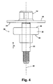
- Figure 4 is a front elevational view of a partially assembled power seal bolt assembly of Figure 1 ;
- Figure 5 is a front elevational view of a compressible washer retainer of the present disclosure
- Figure 6 is a top plan view of the compressible washer retainer of Figure 5 ;
- Figure 7 is a cross sectional plan view taken at section 7 of Figure 5 of the retainer portion of the compressible washer retainer;
- Figure 8 is a partial cross sectional elevational view of a completed installation of a power seal bolt assembly of the present disclosure.
- Figure 9 is a partial cross sectional elevational view of a completed installation of an additional embodiment of a power seal bolt assembly of the present disclosure.
- a power seal bolt assembly 10 of the present disclosure can include a bolt 12 having a head 14 homogeneously connected to a head engagement flange 16. Head engagement flange 16 can abut against a first outer face 18 of a washer 20.
- Bolt 12 further includes a shaft 21 having an unthreaded shaft portion 22, a threaded portion 24, and an anti-cross-thread end 26.
- Unthreaded shaft portion 22 extends homogenously from head engagement flange 16, with threaded portion 24 and anti-cross-thread end 26 extending away from unthreaded shaft portion 22.
- Unthreaded shaft portion 22 has a shaft diameter "A”.
- Threaded portion 24 has a thread pitch "B" which defines a diameter smaller than shaft diameter "A”.
- a polymeric material compressible washer retainer 28 which can by made by a molding operation is slidably fit over the unthreaded shaft portion 22.
- Compressible washer retainer 28 includes a retainer portion 30 which is adapted to slidably and frictionally engage the unthreaded shaft portion 22.
- Compressible washer retainer 28 further includes a compressible washer portion 32 homogenously connected to retainer portion 30.
- Compressible washer retainer 28 is slidably disposed over unthreaded shaft portion 22 until compressible washer portion 32 contacts a second inner face 34 of washer 20.
- Compressible washer retainer 28 is thereafter frictionally retained in the position shown in Figure 1 by frictional engagement between retainer portion 30 and unthreaded shaft portion 22 which will be described in greater detail in reference to Figures 5-7 .
- a bolt-washer assembly 36 is created by sliding washer 20 over the unthreaded shaft portion 22 of bolt 12.
- a positive engagement feature 38 such as a knurl is created after washer 20 engages head engagement flange 16 so that washer 20 is fixedly retained in contact with head engagement flange 16.
- bolt-washer assembly 36 has a working stem length "C” measured from the second inner face 34 to a free end 39 of anti-cross-thread end 26.
- Working stem length "C” includes a shaft length "D" of unthreaded shaft portion 22 plus a threaded portion length "E” of threaded portion 24 and anti-cross-thread end 26.
- Each of working stem length “C”, shaft length “D”, and threaded portion length “E” can be varied at the discretion of the manufacturer to suit different engagement lengths for bolt 12.
- a total stem length “F” is measured from head engagement flange 16 to the free end 39.
- Working stem length “C” differs from total stem length “F” by a thickness of washer 20.
- head 14 is provided with a plurality of engagement faces 40 defining a geometric shape such as a hexagon for head 14. The quantity of engagement faces 40 is predetermined to suit a standard tool size used for installation of bolt 12.
- head engagement flange 16 has an engagement flange diameter "G”
- washer 20 has a washer diameter "H” which is larger than engagement flange diameter "G”.
- a flat-to-flat spacing dimension "J" is common between opposing ones of the engagement faces 40, for example between engagement faces 40' and 40".
- compressible washer retainer 28 is slidably disposed over unthreaded shaft portion 22 in an installation direction "K" until a contact end 44 of compressible washer portion 32 contacts second inner face 34 of washer 20.
- Compressible washer retainer 28 and unthreaded shaft portion 22 are each co-axially aligned with a longitudinal axis 46 of bolt 12.
- compressible washer retainer 28 is created by co-molding compressible washer portion 32 with the retainer portion 30 during a molding process such as an injection molding process.
- Retainer portion 30 is modified from the retainer disclosed in United States Patent 7,073,997, issued July 11, 2006 , and commonly owned by the assignee of the present disclosure, the subject matter of which is incorporated herein by reference.
- Retainer portion 30 has a retainer length "L”, a retainer outer diameter “M”, and a retainer end diameter “N” measured at a retainer free end 48 of retainer portion 30.
- a circular-shaped slot 50 is created on opposed sides or faces of compressible washer portion 32 and positioned between each of a first outer raised ring 52 and a second inner raised ring 54.
- First and second outer and inner raised rings 52, 54 are duplicated as substantially mirror images of each other formed on an opposite side of compressible washer portion 32 and are therefore identified as first and second outer and inner raised rings 52', 54' on an upwardly directed face of compressible washer portion 32 as viewed in Figure 5 .
- a plurality of partial cavities 56 are created in the faces defined by circular slots 50, 50'.
- Partial cavities 56 are formed in each of the faces defined by circular slots 50, 50' however this quantity can vary above or below the quantity of eight at the discretion of the manufacturer. Partial cavities 56, 56' are provided in part to allow for compression of compressible washer portion 32 when an axial load from bolt 12 (not shown in this view) is induced on compressible washer portion 32 by applying a torque to bolt 12.
- Compressible washer portion 32 has a washer portion length "P". Each of the partial cavities 56, 56' have a partial cavity depth "Q”. A depth of circular slots 50, 50' can also be controlled by the manufacturer to provide additional capability for compression or to resist compression of compressible washer portion 32.
- First and second outer and inner raised rings 52, 54 also provide fluid seal function as a seal for fluids or gasses when compressible washer portion 32 is compressed during use.
- a plurality of flexible legs 58 extend into a through aperture 60 of compressible washer retainer 28. Free ends of each of the flexible legs 58 define a flexible leg contact circle "R" which is smaller than shaft diameter "A" of unthreaded shaft portion 22. This difference in diameter dimension induces the flexible legs 58 to deflect outwardly when compressible washer retainer 28 is disposed onto unthreaded shaft portion 22 of bolt 12. Clearance for deflection of each of the flexible legs 58 as unthreaded shaft portion 22 is received is provided by a clearance provided between flexible leg contact circle "R” and an inner wall diameter "S" of retainer portion 30.
- each of the flexible legs 58 such as exemplary flexible leg 50' defines a leg orientation angle ⁇ with respect to a reference line 61 oriented normal to an inner wall 68 of retainer portion 30.
- Each of the flexible legs 58 has a first leg face 62 and an opposite second leg face 64 each commonly oriented with respect to the other flexible legs 58.
- a leg free end 66 of each of the flexible legs 58 is oriented to face the unthreaded shaft portion 22 (not shown) of bolt 12 in the as-molded condition of retainer portion 30.
- Each of the flexible legs 58 are homogenously created and extend into through aperture 60 from inner wall 68 with retainer portion 30 in an as-molded condition.
- a completed installation 70 of power seal bolt assembly 10 utilizes power seal bolt assembly 10 to releasably fasten a polymeric member 72 such as a valve head cover for an automobile engine to a metal member 74 such as an engine block.
- Completed installation 70 is provided by inserting power seal bolt assembly 10 in an insertion direction "T" such that compressible washer portion 32 is received in a counter-bore 76 created in polymeric member 72.
- retainer portion 30 is frictionally received within a through aperture 78 of polymeric member 72.
- a through aperture diameter "V” of through aperture 78 is smaller than retainer outer diameter "M” of retainer portion 30 such that an interference or frictional fit is obtained between retainer portion 30 and an inner wall 79 defined by through aperture 78.
- Threaded portion 24 of bolt 12 is threadably engaged with a threaded bore 80 created in metal member 74.
- Threaded bore 80 can be a closed bore such as the bore shown in Figure 8 , or can also be a through threaded bore at the discretion of the manufacturer.
- Bolt 12 is rotated to complete the installation 70 such that threaded portion 24 in engagement with threaded bore 80 further pulls bolt 12 in the insertion direction "T" until shaft end face 42 of unthreaded shaft portion 22 contacts a contact surface 82 of metal member 74.
- a counter-bore depth "U” of counter-bore 76 is less than the washer portion length "P" of compressible washer portion 32.
- compressible washer portion 32 The greater thickness or length of compressible washer portion 32 compared to counter-bore depth "U" promotes compression of compressible washer portion 32 as bolt 12 is torqued into position. Axial compression of compressible washer portion 32 continues until second inner face 34 of washer 20 contacts a member outer surface 84 of polymeric member 72. During compression of compressible washer portion 32, the first and second outer and inner raised rings 52, 52' and 54, 54' respectively create fluid seals with each of the second inner face 34 of washer 20 and a counter-bore end face 86 of counter-bore 76. Contact between shaft end face 42 of unthreaded shaft portion 22 and the contact surface 82 of metal member 74 also creates a compression limiting capability for power seal bolt assembly 10 to limit the compressive force applied to polymeric member 72 by bolt 12.
- the bolt-washer assembly 36 can be received within polymeric member 72 such that frictional contact between retainer portion 30 and inner wall 79 of polymeric member 72 will retain power seal bolt assembly 10 in frictional engagement with polymeric member 72 prior to engagement between threaded portion 24 and threaded bore 80 of metal member 74.
- This provides a capability of preloading power seal bolt assemblies 10 in one or more locations of polymeric member 72 for shipment of polymeric member 72 to an installation facility and subsequent installation of polymeric member 72 with metal member 74.
- bolt 12 is frictionally held by contact with each of the flexible legs 58 during this interim period and before the completed installation 70 of Figure 8 is created.
- a completed installation 70' of power seal bolt assembly 10' utilizes power seal bolt assembly 10' to releasably fasten a polymeric member 72' such as a valve head cover for an automobile engine to metal member 74 such as an engine block.
- Polymeric member 72' is modified from polymeric member 72 to include a reduced total height "W" and to eliminate counter-bore 76.
- a compressible washer portion 32' is modified from compressible washer portion 32 such that compressible washer portion 32' is adapted to separately receive a retainer portion 30' such that compressible washer portion 32' and retainer portion 30' are not required to be homogenously connected.
- Retainer portion 30' can include an insertion portion 88 partially received in and frictionally engaged by compressible washer portion 32'.
- Completed installation 70' is created by inserting power seal bolt assembly 10 in insertion direction "T" such that compressible washer portion 32' directly contacts an outer facing surface 90 of polymeric member 72'.
- retainer portion 30' is frictionally received within a through aperture 78' of polymeric member 72'.
- a through aperture diameter "V" of through aperture 78' is smaller than retainer outer diameter "M” of retainer portion 30' such that an interference or frictional fit is obtained between retainer portion 30' and an inner wall 79' defined by through aperture 78'.
- Threaded portion 24 of bolt 12 is threadably engaged with threaded bore 80 created in metal member 74.
- Bolt 12 is rotated to complete the installation 70' such that threaded portion 24 in engagement with threaded bore 80 further pulls bolt 12 in the insertion direction "T" until shaft end face 42 of unthreaded shaft portion 22 contacts the contact surface 82 of metal member 74.
- washer portion length "P" of compressible washer portion 32' is reduced by compression of compressible washer portion 32', and a gasket 92 installed between polymeric member 72' and metal member 74 is also partially compressed.
- first and second outer and inner raised rings 52, 52' and 54, 54' can be entirely eliminated from compressible washer portion 32', or only one each of first and second outer and inner raised rings 52 or 52' and 54 or 54' can be used.
- a diameter of a modified washer 20' can be substantially equal to a diameter of compressible washer portion 32'.
- Power seal bolt assemblies 10, 10' of the present disclosure provide several advantages.
- a one-piece molded part or a frictionally engaged assembly can be used which provides both a retention capability for bolt 12 and frictional engagement of compressible washer retainer 28 with polymeric member 72 so the power seal bolt assembly 10 can be pre-inserted and shipped with polymeric member 72.
- a compressible feature of compressible washer portion 32 a fluid-tight seal can also be created when power seal bolt assemblies 10 of the present disclosure are torqued into position.
- a compression limiting capability is also provided for power seal bolt assembly 10.
- the compressible feature of compressible washer portion 32 also includes compensation for misalignment and construction tolerances between the first and second workpieces. Also, by controlling a total length of unthreaded shaft portion 22 and threaded portion 24 of bolt 12, different thicknesses for the polymeric member 72 can be accommodated using a commonly sized compressible washer retainer 28 of the present disclosure.
Landscapes
- Engineering & Computer Science (AREA)
- General Engineering & Computer Science (AREA)
- Mechanical Engineering (AREA)
- Bolts, Nuts, And Washers (AREA)
Abstract
Description
- This application claims the benefit of
U.S. Provisional Application No. 60/987,910, filed on November 14, 2007 - The present disclosure relates to devices and methods for use of pre-assembled fastener assemblies used to fasten a first workpiece to a second workpiece where the workpieces include different materials.
- The statements in this section merely provide background information related to the present disclosure and may not constitute prior art.
- Fastening members are widely used to join materials of different properties to one another including applications such as fastening plastic or polymeric parts such as covers and trim pieces to metal components or parts of an automobile vehicle assembly. One such device is disclosed in United States Patent
5,807,052 to Van Boven et al . The '052 patent defines an assembly for bearing the load from a metallic fastener coupled through a plastic part to a vehicle metallic part. Several disadvantages exist for the design of the device of the '052 patent. These include the incorporation of a springing flange into the design of a sleeve which requires additional machining to achieve the springing function with the required clearance to permit the flange to deflect during assembly of the fastener. A further disadvantage is the fastener itself must be specially machined or formed having a protruding shank rib member to prevent the fastener from releasing from the sleeve assembly prior to installation. - Further disadvantages of the design of the '052 patent include a machining or forming process required on the internal bore of the sleeve to create a stop which engages the shank rib member. This machining or forming process removes material from the sleeve and is accomplished inside the sleeve bore and therefore generally increases the cost of the sleeve. A lower or second flange created on the sleeve further increases the cost of the sleeve by requiring an additional operation to create the flange or a machining operation to remove material to create the flange.
- Plastic or polymeric components such as valve covers used in conjunction with an automobile vehicle engine block reduce the cost and weight of the cover, however the thermal cycling over time and/or the stress/strain over time of the cover can generate creep in the plastic material used for the cover and a subsequently loose connection between the cover and the engine block. A reduced complexity fastener assembly is therefore warranted for this application as well as additional applications where dissimilar materials are fastened.
- According to an embodiment of the present disclosure, a power seal bolt assembly includes a bolt having a head and a shaft having an unthreaded shaft portion and a threaded portion. Preferably 9. A washer is fixed to the bolt proximate to the head. A compressible washer retainer frictionally engages the unthreaded shaft portion and contacts the head. The compressible washer retainer includes a retainer portion having flexible legs extending inwardly into a washer retainer through aperture. The flexible legs flex to frictionally engage the retainer portion to the unthreaded shaft portion. A compressible washer portion homogenously connected to the retainer portion is oriented to contact the washer when a bolt torque is applied. The compressible washer portion preferably includes at least one raised ring contacting the washer to create a fluid seal at the washer; and at least one partial cavity permitting the compression washer portion to axially compress upon application of the torque.
- Further areas of applicability will become apparent from the description provided herein. It should be understood that the description and specific examples are intended for purposes of illustration only and are not intended to limit the scope of the present disclosure.
- The drawings described herein are for illustration purposes only and are not intended to limit the scope of the present disclosure in any way.
-
Figure 1 is a front elevational view of a power seal bolt assembly of the present disclosure; -
Figure 2 is a front elevational view of a bolt-washer assembly for the power seal bolt assembly ofFigure 1 ; -
Figure 3 is a top plan view of the bolt-washer assembly ofFigure 2 ; -
Figure 4 is a front elevational view of a partially assembled power seal bolt assembly ofFigure 1 ; -
Figure 5 is a front elevational view of a compressible washer retainer of the present disclosure; -
Figure 6 is a top plan view of the compressible washer retainer ofFigure 5 ; -
Figure 7 is a cross sectional plan view taken atsection 7 ofFigure 5 of the retainer portion of the compressible washer retainer; -
Figure 8 is a partial cross sectional elevational view of a completed installation of a power seal bolt assembly of the present disclosure; and -
Figure 9 is a partial cross sectional elevational view of a completed installation of an additional embodiment of a power seal bolt assembly of the present disclosure. - The following description is merely exemplary in nature and is not intended to limit the present disclosure, application, or uses. It should be understood that throughout the drawings, corresponding reference numerals indicate like or corresponding parts and features.
- Referring to
Figure 1 , a powerseal bolt assembly 10 of the present disclosure can include abolt 12 having ahead 14 homogeneously connected to ahead engagement flange 16.Head engagement flange 16 can abut against a firstouter face 18 of awasher 20.Bolt 12 further includes ashaft 21 having anunthreaded shaft portion 22, a threadedportion 24, and an anti-cross-thread end 26. Unthreadedshaft portion 22 extends homogenously fromhead engagement flange 16, with threadedportion 24 and anti-cross-thread end 26 extending away fromunthreaded shaft portion 22. Unthreadedshaft portion 22 has a shaft diameter "A". Threadedportion 24 has a thread pitch "B" which defines a diameter smaller than shaft diameter "A". - A polymeric material
compressible washer retainer 28 which can by made by a molding operation is slidably fit over theunthreaded shaft portion 22.Compressible washer retainer 28 includes aretainer portion 30 which is adapted to slidably and frictionally engage theunthreaded shaft portion 22.Compressible washer retainer 28 further includes acompressible washer portion 32 homogenously connected toretainer portion 30.Compressible washer retainer 28 is slidably disposed overunthreaded shaft portion 22 untilcompressible washer portion 32 contacts a secondinner face 34 ofwasher 20.Compressible washer retainer 28 is thereafter frictionally retained in the position shown inFigure 1 by frictional engagement betweenretainer portion 30 andunthreaded shaft portion 22 which will be described in greater detail in reference toFigures 5-7 . - Referring to
Figure 2 and back toFigure 1 , prior to installation of compressible washer retainer 28 a bolt-washer assembly 36 is created by slidingwasher 20 over theunthreaded shaft portion 22 ofbolt 12. Apositive engagement feature 38 such as a knurl is created after washer 20 engageshead engagement flange 16 so thatwasher 20 is fixedly retained in contact withhead engagement flange 16. In the assembled condition shown, bolt-washer assembly 36 has a working stem length "C" measured from the secondinner face 34 to afree end 39 of anti-cross-thread end 26. Working stem length "C" includes a shaft length "D" ofunthreaded shaft portion 22 plus a threaded portion length "E" of threadedportion 24 and anti-cross-thread end 26. Each of working stem length "C", shaft length "D", and threaded portion length "E" can be varied at the discretion of the manufacturer to suit different engagement lengths forbolt 12. A total stem length "F" is measured fromhead engagement flange 16 to thefree end 39. Working stem length "C" differs from total stem length "F" by a thickness ofwasher 20. According toseveral embodiments head 14 is provided with a plurality of engagement faces 40 defining a geometric shape such as a hexagon forhead 14. The quantity of engagement faces 40 is predetermined to suit a standard tool size used for installation ofbolt 12. - Referring to
Figure 3 ,head engagement flange 16 has an engagement flange diameter "G", andwasher 20 has a washer diameter "H" which is larger than engagement flange diameter "G". A flat-to-flat spacing dimension "J" is common between opposing ones of the engagement faces 40, for example between engagement faces 40' and 40". - Referring to
Figure 4 , after assembly of bolt-washer assembly 36,compressible washer retainer 28 is slidably disposed over unthreadedshaft portion 22 in an installation direction "K" until acontact end 44 ofcompressible washer portion 32 contacts secondinner face 34 ofwasher 20.Compressible washer retainer 28 and unthreadedshaft portion 22 are each co-axially aligned with alongitudinal axis 46 ofbolt 12. - Referring to
Figures 5 and 6 ,compressible washer retainer 28 is created by co-moldingcompressible washer portion 32 with theretainer portion 30 during a molding process such as an injection molding process.Retainer portion 30 is modified from the retainer disclosed in United States Patent7,073,997, issued July 11, 2006 , and commonly owned by the assignee of the present disclosure, the subject matter of which is incorporated herein by reference. -
Retainer portion 30 has a retainer length "L", a retainer outer diameter "M", and a retainer end diameter "N" measured at a retainerfree end 48 ofretainer portion 30. A circular-shapedslot 50 is created on opposed sides or faces ofcompressible washer portion 32 and positioned between each of a first outer raisedring 52 and a second inner raisedring 54. First and second outer and inner raised rings 52, 54 are duplicated as substantially mirror images of each other formed on an opposite side ofcompressible washer portion 32 and are therefore identified as first and second outer and inner raised rings 52', 54' on an upwardly directed face ofcompressible washer portion 32 as viewed inFigure 5 . A plurality ofpartial cavities 56 are created in the faces defined bycircular slots 50, 50'. In the example shown, eightpartial cavities 56 are formed in each of the faces defined bycircular slots 50, 50' however this quantity can vary above or below the quantity of eight at the discretion of the manufacturer.Partial cavities 56, 56' are provided in part to allow for compression ofcompressible washer portion 32 when an axial load from bolt 12 (not shown in this view) is induced oncompressible washer portion 32 by applying a torque to bolt 12. -
Compressible washer portion 32 has a washer portion length "P". Each of thepartial cavities 56, 56' have a partial cavity depth "Q". A depth ofcircular slots 50, 50' can also be controlled by the manufacturer to provide additional capability for compression or to resist compression ofcompressible washer portion 32. First and second outer and inner raised rings 52, 54 also provide fluid seal function as a seal for fluids or gasses whencompressible washer portion 32 is compressed during use. - Referring more specifically to
Figures 1 and6 , a plurality offlexible legs 58 extend into a throughaperture 60 ofcompressible washer retainer 28. Free ends of each of theflexible legs 58 define a flexible leg contact circle "R" which is smaller than shaft diameter "A" ofunthreaded shaft portion 22. This difference in diameter dimension induces theflexible legs 58 to deflect outwardly whencompressible washer retainer 28 is disposed onto unthreadedshaft portion 22 ofbolt 12. Clearance for deflection of each of theflexible legs 58 as unthreadedshaft portion 22 is received is provided by a clearance provided between flexible leg contact circle "R" and an inner wall diameter "S" ofretainer portion 30. - Referring now to
Figure 7 , a quantity of eight (8)flexible legs 58 are shown, however the quantity offlexible legs 58 can vary either above or below the quantity of eight at the discretion of the manufacturer and to suit the required frictional contact if shaft diameter "A" ofunthreaded shaft portion 22 changes for different embodiments. Each of theflexible legs 58 such as exemplary flexible leg 50' defines a leg orientation angle α with respect to areference line 61 oriented normal to aninner wall 68 ofretainer portion 30. Each of theflexible legs 58 has afirst leg face 62 and an oppositesecond leg face 64 each commonly oriented with respect to the otherflexible legs 58. A legfree end 66 of each of theflexible legs 58 is oriented to face the unthreaded shaft portion 22 (not shown) ofbolt 12 in the as-molded condition ofretainer portion 30. Each of theflexible legs 58 are homogenously created and extend into throughaperture 60 frominner wall 68 withretainer portion 30 in an as-molded condition. - Referring to
Figure 8 and again toFigure 5 , a completedinstallation 70 of powerseal bolt assembly 10 utilizes powerseal bolt assembly 10 to releasably fasten apolymeric member 72 such as a valve head cover for an automobile engine to ametal member 74 such as an engine block. Completedinstallation 70 is provided by inserting powerseal bolt assembly 10 in an insertion direction "T" such thatcompressible washer portion 32 is received in a counter-bore 76 created inpolymeric member 72. At the same time,retainer portion 30 is frictionally received within a throughaperture 78 ofpolymeric member 72. A through aperture diameter "V" of throughaperture 78 is smaller than retainer outer diameter "M" ofretainer portion 30 such that an interference or frictional fit is obtained betweenretainer portion 30 and aninner wall 79 defined by throughaperture 78. - Threaded
portion 24 ofbolt 12 is threadably engaged with a threadedbore 80 created inmetal member 74. Threaded bore 80 can be a closed bore such as the bore shown inFigure 8 , or can also be a through threaded bore at the discretion of the manufacturer.Bolt 12 is rotated to complete theinstallation 70 such that threadedportion 24 in engagement with threadedbore 80 further pullsbolt 12 in the insertion direction "T" until shaft end face 42 of unthreadedshaft portion 22 contacts acontact surface 82 ofmetal member 74. A counter-bore depth "U" ofcounter-bore 76 is less than the washer portion length "P" ofcompressible washer portion 32. The greater thickness or length ofcompressible washer portion 32 compared to counter-bore depth "U" promotes compression ofcompressible washer portion 32 asbolt 12 is torqued into position. Axial compression ofcompressible washer portion 32 continues until secondinner face 34 ofwasher 20 contacts a memberouter surface 84 ofpolymeric member 72. During compression ofcompressible washer portion 32, the first and second outer and inner raised rings 52, 52' and 54, 54' respectively create fluid seals with each of the secondinner face 34 ofwasher 20 and a counter-bore end face 86 ofcounter-bore 76. Contact between shaft end face 42 of unthreadedshaft portion 22 and thecontact surface 82 ofmetal member 74 also creates a compression limiting capability for powerseal bolt assembly 10 to limit the compressive force applied topolymeric member 72 bybolt 12. - Referring again to each of
Figures 4 and8 , withcompressible washer retainer 28 positioned on unthreadedshaft portion 22 as shown inFigure 4 , the bolt-washer assembly 36 can be received withinpolymeric member 72 such that frictional contact betweenretainer portion 30 andinner wall 79 ofpolymeric member 72 will retain powerseal bolt assembly 10 in frictional engagement withpolymeric member 72 prior to engagement between threadedportion 24 and threaded bore 80 ofmetal member 74. This provides a capability of preloading powerseal bolt assemblies 10 in one or more locations ofpolymeric member 72 for shipment ofpolymeric member 72 to an installation facility and subsequent installation ofpolymeric member 72 withmetal member 74. With further reference also toFigure 7 ,bolt 12 is frictionally held by contact with each of theflexible legs 58 during this interim period and before the completedinstallation 70 ofFigure 8 is created. - Referring to
Figure 9 , and again toFigures 5 and8 , a completed installation 70' of power seal bolt assembly 10' utilizes power seal bolt assembly 10' to releasably fasten a polymeric member 72' such as a valve head cover for an automobile engine tometal member 74 such as an engine block. Polymeric member 72' is modified frompolymeric member 72 to include a reduced total height "W" and to eliminatecounter-bore 76. A compressible washer portion 32' is modified fromcompressible washer portion 32 such that compressible washer portion 32' is adapted to separately receive a retainer portion 30' such that compressible washer portion 32' and retainer portion 30' are not required to be homogenously connected. Retainer portion 30' can include aninsertion portion 88 partially received in and frictionally engaged by compressible washer portion 32'. Completed installation 70' is created by inserting powerseal bolt assembly 10 in insertion direction "T" such that compressible washer portion 32' directly contacts an outer facingsurface 90 of polymeric member 72'. At the same time, retainer portion 30' is frictionally received within a through aperture 78' of polymeric member 72'. A through aperture diameter "V" of through aperture 78' is smaller than retainer outer diameter "M" of retainer portion 30' such that an interference or frictional fit is obtained between retainer portion 30' and an inner wall 79' defined by through aperture 78'. - Threaded
portion 24 ofbolt 12 is threadably engaged with threadedbore 80 created inmetal member 74.Bolt 12 is rotated to complete the installation 70' such that threadedportion 24 in engagement with threadedbore 80 further pullsbolt 12 in the insertion direction "T" until shaft end face 42 of unthreadedshaft portion 22 contacts thecontact surface 82 ofmetal member 74. During threaded engagement of threadedportion 24 washer portion length "P" of compressible washer portion 32' is reduced by compression of compressible washer portion 32', and agasket 92 installed between polymeric member 72' andmetal member 74 is also partially compressed. - Combined axial compression of compressible washer portion 32' and
gasket 92 continues until shaft end face 42 of unthreadedshaft portion 22contacts contact surface 82 ofmetal member 74. During compression of compressible washer portion 32'. With further reference toFigure 8 , the first and second outer and inner raised rings 52, 52' and 54, 54' can be entirely eliminated from compressible washer portion 32', or only one each of first and second outer and inner raisedrings - Power
seal bolt assemblies 10, 10' of the present disclosure provide several advantages. By co-molding and combining or frictionally engaging thecompressible washer portion 32 with theretainer portion 30 to createcompressible washer retainer 28, a one-piece molded part or a frictionally engaged assembly can be used which provides both a retention capability forbolt 12 and frictional engagement ofcompressible washer retainer 28 withpolymeric member 72 so the powerseal bolt assembly 10 can be pre-inserted and shipped withpolymeric member 72. By providing a compressible feature of compressible washer portion 32 a fluid-tight seal can also be created when powerseal bolt assemblies 10 of the present disclosure are torqued into position. In addition, by incorporating the shaft end face 42 onto unthreadedshaft portion 22 of bolt 12 a compression limiting capability is also provided for powerseal bolt assembly 10. The compressible feature ofcompressible washer portion 32 also includes compensation for misalignment and construction tolerances between the first and second workpieces. Also, by controlling a total length of unthreadedshaft portion 22 and threadedportion 24 ofbolt 12, different thicknesses for thepolymeric member 72 can be accommodated using a commonly sizedcompressible washer retainer 28 of the present disclosure.
Claims (15)
- A power seal bolt assembly (10), comprising:a bolt (12) having a head (14), a head engagement flange (16), and a shaft (21) extending from the head engagement flange (16) having an unthreaded shaft portion (22) proximate the head engagement flange (16) and a threaded portion (24), anda polymeric compressible washer retainer (28), including:a retainer portion (30) having flexible legs (58) extending inwardly into a through aperture (60) of the compressible washer retainer (28), the flexible legs (58) adapted to flex to frictionally engage the retainer portion (30) to the unthreaded shaft portion (22), anda compressible washer portion (32) positioned between the retainer portion (30) and the head engagement flange (16), the compressible washer portion (32) adapted to axially compress upon application of a torque to the bolt (12).
- The power seal bolt assembly of claim 1, further including:a washer (20) slidably received on the unthreaded shaft portion (22) of the bolt (12) and in contact with the head engagement flange (16); anda contact face of the compressible washer portion (32) adapted to contact the washer (20).
- The power seal bolt assembly of claim 2, further including a positive engagement feature (38) created in the unthreaded shaft portion (22) after installation of the washer (20) the positive engagement feature (38) preventing removal of the washer (20).
- The power seal bolt assembly of claim 3, wherein the positive engagement feature (38) comprises a knurl.
- The power seal bolt assembly of any of claims 1-4, wherein the compressible washer portion (32) includes:at least one raised ring (52, 54); andat least one partial cavity (56) permitting the compressible washer portion (32) to axially compress upon application of the torque to the bolt (12).
- The power seal bolt assembly of claim 5, wherein the at least one raised ring (52, 54) is adapted to contact the washer (20) to create a fluid seal at the washer (20).
- The power seal bolt assembly of claim 5 or 6, wherein the at least one raised ring (52, 54) includes first and second raised rings (52, 54) separated by a slot (50).
- The power seal bolt assembly of claim 7, wherein the at least one partial cavity (56) is positioned in the slot (50) between the first and second raised rings (52, 54).
- The power seal bolt assembly of any of claims 1-8, further including:a polymeric member (72) having a counter-bore (76), the bolt (12) having the compressible washer retainer (28) connected thereto inserted through the polymeric member (72) such that the compressible washer portion (32) is received in the counter bore (76);wherein the polymeric member (72) includes a through aperture (78) coaxially with the counter-bore (76), wherein simultaneously during insertion of the bolt (12) the retainer portion (30) is frictionally received within the through aperture (78).
- The assembly of claim 9, further including an inner wall (79) defined by the through aperture (78) having a diameter (V) smaller than an outer diameter (M) of the retainer portion (30) such that a frictional fit is created between the retainer portion (30) and the inner wall (79).
- The assembly of claim 9 or 10, further including:a metal member (74), wherein the threaded portion (24) of the bolt (12) is threadably engaged with a threaded bore (80) created in the metal member (74),a shaft end face (42) of the unthreaded shaft portion (22); anda contact surface (82) of the metal member (74),wherein the bolt (12) is rotatable such that the threaded portion (24) in threaded engagement with the threaded bore (80) operates to pull the bolt (12) in an insertion direction (T) until the shaft end face (42) of the unthreaded shaft portion (22) contacts the contact surface (82) of the metal member (74) precluding further compression of the compressible washer portion (32).
- The power seal bolt assembly of any of claims 1-11, wherein:each of the flexible legs (58) define a leg orientation angle (α) with respect to a reference line (61) oriented normal to an inner wall (68) of the retainer portion (30);each of the flexible legs (58) includes a first leg face (62) and an opposite second leg face (64) each commonly oriented with respect to the other flexible legs (58); andthe flexible legs (58) are homogenously connected to the inner wall (68) of the retainer portion (30) and extend into the through aperture (60).
- The power seal bolt assembly of any of claims 1-12, wherein the compressible washer portion (32) is homogenously connected to the retainer portion (30).
- The power seal bolt assembly of any of claims 1-13, wherein each of the flexible legs (58) define a leg orientation angle (α) with respect to a reference line (61) oriented normal to an inner wall (68) of the retainer portion (30).
- The power seal bolt assembly of any of claims 1-14, wherein each of the flexible legs (58) includes:a first leg face (62) and an opposite second leg face (64) each commonly oriented with respect to the other flexible legs (58); anda leg free end (66) oriented to face the unthreaded shaft portion (22) of the bolt (12),wherein the flexible legs (58) are homogenously connected to an inner wall (68) of the retainer portion (30) and extend into the through aperture (60) from the inner wall (68).
Applications Claiming Priority (2)
| Application Number | Priority Date | Filing Date | Title |
|---|---|---|---|
| US98791007P | 2007-11-14 | 2007-11-14 | |
| US12/267,882 US7753633B2 (en) | 2007-11-14 | 2008-11-10 | Power seal bolt assembly |
Publications (2)
| Publication Number | Publication Date |
|---|---|
| EP2060802A2 true EP2060802A2 (en) | 2009-05-20 |
| EP2060802A3 EP2060802A3 (en) | 2010-07-07 |
Family
ID=40350073
Family Applications (1)
| Application Number | Title | Priority Date | Filing Date |
|---|---|---|---|
| EP08019655A Withdrawn EP2060802A3 (en) | 2007-11-14 | 2008-11-11 | Power seal bolt assembly |
Country Status (1)
| Country | Link |
|---|---|
| EP (1) | EP2060802A3 (en) |
Cited By (1)
| Publication number | Priority date | Publication date | Assignee | Title |
|---|---|---|---|---|
| CN102278471A (en) * | 2011-07-13 | 2011-12-14 | 河南师范大学 | Plugging bolt |
Citations (2)
| Publication number | Priority date | Publication date | Assignee | Title |
|---|---|---|---|---|
| US5807052A (en) | 1997-06-27 | 1998-09-15 | Illinois Tool Works Inc. | Pre-assembled manifold fastener system and method therefor |
| US7073997B2 (en) | 2002-10-02 | 2006-07-11 | Newfrey Llc | Apparatus and method for holding a piece in a bore |
Family Cites Families (4)
| Publication number | Priority date | Publication date | Assignee | Title |
|---|---|---|---|---|
| US2303224A (en) * | 1938-08-27 | 1942-11-24 | Illinois Tool Works | Method and means for assembling screws and lock washers |
| US4975008A (en) * | 1989-03-31 | 1990-12-04 | Illinois Tool Works, Inc. | Fastener assembly with sealing grommet |
| US6059503A (en) * | 1998-10-27 | 2000-05-09 | Johnson; H. Thad | Captivated fastener assembly |
| DE10104672B4 (en) * | 2001-02-02 | 2004-04-15 | Kamax-Werke Rudolf Kellermann Gmbh & Co. Kg | Assembly unit consisting of one component and at least one screw |
-
2008
- 2008-11-11 EP EP08019655A patent/EP2060802A3/en not_active Withdrawn
Patent Citations (2)
| Publication number | Priority date | Publication date | Assignee | Title |
|---|---|---|---|---|
| US5807052A (en) | 1997-06-27 | 1998-09-15 | Illinois Tool Works Inc. | Pre-assembled manifold fastener system and method therefor |
| US7073997B2 (en) | 2002-10-02 | 2006-07-11 | Newfrey Llc | Apparatus and method for holding a piece in a bore |
Cited By (1)
| Publication number | Priority date | Publication date | Assignee | Title |
|---|---|---|---|---|
| CN102278471A (en) * | 2011-07-13 | 2011-12-14 | 河南师范大学 | Plugging bolt |
Also Published As
| Publication number | Publication date |
|---|---|
| EP2060802A3 (en) | 2010-07-07 |
Similar Documents
| Publication | Publication Date | Title |
|---|---|---|
| US7753633B2 (en) | Power seal bolt assembly | |
| US7708512B2 (en) | Compression limiter | |
| JP2552233B2 (en) | Fastener assembly for drain plug | |
| TWI596284B (en) | Fastener with attached compression limiting sleeve | |
| US6327854B1 (en) | Fastening an exhaust manifold to an engine cylinder head | |
| KR101924914B1 (en) | Quick fastener, method for connecting two components by means of the quick fastener and production method thereof | |
| AU653262B2 (en) | Composite drain plug construction | |
| US20080056816A1 (en) | Quick connect closure for connecting two structural members | |
| US3273441A (en) | Nut construction | |
| CN102242675A (en) | Flange fastening structure | |
| GB2270360A (en) | Assembly of shaft and hub | |
| CN101243260A (en) | Tolerance Compensation Connections | |
| CN108317228B (en) | Chain tensioner | |
| US6183370B1 (en) | Dust cap assembly having two snap ring securing mechanism in a slip spline assembly | |
| CN210859487U (en) | System for fastening two components together and system for attaching two components | |
| JPH11101218A (en) | Metallic collar and fastening structure using the same | |
| US20080080928A1 (en) | Universal end fitting and fastener assembly comprising such an end fitting | |
| US20190383315A1 (en) | Compression limiter fastener assembly | |
| US20080145185A1 (en) | Two piece, free running, prevailing torque nut | |
| US12140173B2 (en) | Rivet nut with compression limiter shoulder | |
| JP4070299B2 (en) | Pipe joint structure | |
| US20040062621A1 (en) | Retainer for positioning fasteners in parts, structural members, and the like | |
| EP4069984B1 (en) | Fastener with attached compression limiting sleeve | |
| JP4067509B2 (en) | Fixing device | |
| RU2781164C2 (en) | Retaining device for threaded element, in particular for nut |
Legal Events
| Date | Code | Title | Description |
|---|---|---|---|
| PUAI | Public reference made under article 153(3) epc to a published international application that has entered the european phase |
Free format text: ORIGINAL CODE: 0009012 |
|
| AK | Designated contracting states |
Kind code of ref document: A2 Designated state(s): AT BE BG CH CY CZ DE DK EE ES FI FR GB GR HR HU IE IS IT LI LT LU LV MC MT NL NO PL PT RO SE SI SK TR |
|
| AX | Request for extension of the european patent |
Extension state: AL BA MK RS |
|
| PUAL | Search report despatched |
Free format text: ORIGINAL CODE: 0009013 |
|
| AK | Designated contracting states |
Kind code of ref document: A3 Designated state(s): AT BE BG CH CY CZ DE DK EE ES FI FR GB GR HR HU IE IS IT LI LT LU LV MC MT NL NO PL PT RO SE SI SK TR |
|
| AX | Request for extension of the european patent |
Extension state: AL BA MK RS |
|
| RIC1 | Information provided on ipc code assigned before grant |
Ipc: F16B 41/00 20060101ALI20100531BHEP Ipc: F16B 43/00 20060101ALI20100531BHEP Ipc: F16B 35/04 20060101ALI20100531BHEP Ipc: F16B 31/02 20060101AFI20090220BHEP |
|
| 17P | Request for examination filed |
Effective date: 20110107 |
|
| AKX | Designation fees paid |
Designated state(s): AT BE BG CH CY CZ DE DK EE ES FI FR GB GR HR HU IE IS IT LI LT LU LV MC MT NL NO PL PT RO SE SI SK TR |
|
| 17Q | First examination report despatched |
Effective date: 20121203 |
|
| GRAP | Despatch of communication of intention to grant a patent |
Free format text: ORIGINAL CODE: EPIDOSNIGR1 |
|
| INTG | Intention to grant announced |
Effective date: 20130807 |
|
| STAA | Information on the status of an ep patent application or granted ep patent |
Free format text: STATUS: THE APPLICATION IS DEEMED TO BE WITHDRAWN |
|
| 18D | Application deemed to be withdrawn |
Effective date: 20131218 |