EP2060787A2 - Wind turbine geothermal heating and cooling system - Google Patents
Wind turbine geothermal heating and cooling system Download PDFInfo
- Publication number
- EP2060787A2 EP2060787A2 EP08165567A EP08165567A EP2060787A2 EP 2060787 A2 EP2060787 A2 EP 2060787A2 EP 08165567 A EP08165567 A EP 08165567A EP 08165567 A EP08165567 A EP 08165567A EP 2060787 A2 EP2060787 A2 EP 2060787A2
- Authority
- EP
- European Patent Office
- Prior art keywords
- wind turbine
- tower
- unit
- foundation
- thermal
- Prior art date
- Legal status (The legal status is an assumption and is not a legal conclusion. Google has not performed a legal analysis and makes no representation as to the accuracy of the status listed.)
- Withdrawn
Links
- 238000001816 cooling Methods 0.000 title claims abstract description 17
- 238000010438 heat treatment Methods 0.000 title claims abstract description 13
- 238000004891 communication Methods 0.000 claims abstract description 4
- 238000005086 pumping Methods 0.000 claims description 3
- 239000003570 air Substances 0.000 description 7
- XLYOFNOQVPJJNP-UHFFFAOYSA-N water Substances O XLYOFNOQVPJJNP-UHFFFAOYSA-N 0.000 description 6
- 239000012080 ambient air Substances 0.000 description 3
- 230000005611 electricity Effects 0.000 description 3
- 239000011152 fibreglass Substances 0.000 description 3
- 239000002689 soil Substances 0.000 description 3
- OKTJSMMVPCPJKN-UHFFFAOYSA-N Carbon Chemical compound [C] OKTJSMMVPCPJKN-UHFFFAOYSA-N 0.000 description 2
- 230000005540 biological transmission Effects 0.000 description 2
- 239000004567 concrete Substances 0.000 description 2
- 230000008878 coupling Effects 0.000 description 2
- 238000010168 coupling process Methods 0.000 description 2
- 238000005859 coupling reaction Methods 0.000 description 2
- 238000007710 freezing Methods 0.000 description 2
- 230000008014 freezing Effects 0.000 description 2
- 239000005431 greenhouse gas Substances 0.000 description 2
- 230000033001 locomotion Effects 0.000 description 2
- 239000000463 material Substances 0.000 description 2
- 230000007246 mechanism Effects 0.000 description 2
- 239000011150 reinforced concrete Substances 0.000 description 2
- 239000004593 Epoxy Substances 0.000 description 1
- 229910000831 Steel Inorganic materials 0.000 description 1
- 230000002528 anti-freeze Effects 0.000 description 1
- -1 antifreeze Substances 0.000 description 1
- 230000008901 benefit Effects 0.000 description 1
- 239000002131 composite material Substances 0.000 description 1
- 239000002826 coolant Substances 0.000 description 1
- 229910002804 graphite Inorganic materials 0.000 description 1
- 239000010439 graphite Substances 0.000 description 1
- 239000003562 lightweight material Substances 0.000 description 1
- 238000004519 manufacturing process Methods 0.000 description 1
- 238000000034 method Methods 0.000 description 1
- 230000008569 process Effects 0.000 description 1
- 239000010959 steel Substances 0.000 description 1
- 238000010792 warming Methods 0.000 description 1
- 239000002023 wood Substances 0.000 description 1
Images

Classifications
-
- F—MECHANICAL ENGINEERING; LIGHTING; HEATING; WEAPONS; BLASTING
- F03—MACHINES OR ENGINES FOR LIQUIDS; WIND, SPRING, OR WEIGHT MOTORS; PRODUCING MECHANICAL POWER OR A REACTIVE PROPULSIVE THRUST, NOT OTHERWISE PROVIDED FOR
- F03D—WIND MOTORS
- F03D9/00—Adaptations of wind motors for special use; Combinations of wind motors with apparatus driven thereby; Wind motors specially adapted for installation in particular locations
-
- F—MECHANICAL ENGINEERING; LIGHTING; HEATING; WEAPONS; BLASTING
- F03—MACHINES OR ENGINES FOR LIQUIDS; WIND, SPRING, OR WEIGHT MOTORS; PRODUCING MECHANICAL POWER OR A REACTIVE PROPULSIVE THRUST, NOT OTHERWISE PROVIDED FOR
- F03D—WIND MOTORS
- F03D80/00—Details, components or accessories not provided for in groups F03D1/00 - F03D17/00
- F03D80/60—Cooling or heating of wind motors
-
- F—MECHANICAL ENGINEERING; LIGHTING; HEATING; WEAPONS; BLASTING
- F03—MACHINES OR ENGINES FOR LIQUIDS; WIND, SPRING, OR WEIGHT MOTORS; PRODUCING MECHANICAL POWER OR A REACTIVE PROPULSIVE THRUST, NOT OTHERWISE PROVIDED FOR
- F03D—WIND MOTORS
- F03D13/00—Assembly, mounting or commissioning of wind motors; Arrangements specially adapted for transporting wind motor components
- F03D13/20—Arrangements for mounting or supporting wind motors; Masts or towers for wind motors
- F03D13/22—Foundations specially adapted for wind motors
-
- F—MECHANICAL ENGINEERING; LIGHTING; HEATING; WEAPONS; BLASTING
- F03—MACHINES OR ENGINES FOR LIQUIDS; WIND, SPRING, OR WEIGHT MOTORS; PRODUCING MECHANICAL POWER OR A REACTIVE PROPULSIVE THRUST, NOT OTHERWISE PROVIDED FOR
- F03D—WIND MOTORS
- F03D80/00—Details, components or accessories not provided for in groups F03D1/00 - F03D17/00
-
- F—MECHANICAL ENGINEERING; LIGHTING; HEATING; WEAPONS; BLASTING
- F03—MACHINES OR ENGINES FOR LIQUIDS; WIND, SPRING, OR WEIGHT MOTORS; PRODUCING MECHANICAL POWER OR A REACTIVE PROPULSIVE THRUST, NOT OTHERWISE PROVIDED FOR
- F03D—WIND MOTORS
- F03D9/00—Adaptations of wind motors for special use; Combinations of wind motors with apparatus driven thereby; Wind motors specially adapted for installation in particular locations
- F03D9/10—Combinations of wind motors with apparatus storing energy
-
- Y—GENERAL TAGGING OF NEW TECHNOLOGICAL DEVELOPMENTS; GENERAL TAGGING OF CROSS-SECTIONAL TECHNOLOGIES SPANNING OVER SEVERAL SECTIONS OF THE IPC; TECHNICAL SUBJECTS COVERED BY FORMER USPC CROSS-REFERENCE ART COLLECTIONS [XRACs] AND DIGESTS
- Y02—TECHNOLOGIES OR APPLICATIONS FOR MITIGATION OR ADAPTATION AGAINST CLIMATE CHANGE
- Y02E—REDUCTION OF GREENHOUSE GAS [GHG] EMISSIONS, RELATED TO ENERGY GENERATION, TRANSMISSION OR DISTRIBUTION
- Y02E10/00—Energy generation through renewable energy sources
- Y02E10/70—Wind energy
- Y02E10/72—Wind turbines with rotation axis in wind direction
-
- Y—GENERAL TAGGING OF NEW TECHNOLOGICAL DEVELOPMENTS; GENERAL TAGGING OF CROSS-SECTIONAL TECHNOLOGIES SPANNING OVER SEVERAL SECTIONS OF THE IPC; TECHNICAL SUBJECTS COVERED BY FORMER USPC CROSS-REFERENCE ART COLLECTIONS [XRACs] AND DIGESTS
- Y02—TECHNOLOGIES OR APPLICATIONS FOR MITIGATION OR ADAPTATION AGAINST CLIMATE CHANGE
- Y02E—REDUCTION OF GREENHOUSE GAS [GHG] EMISSIONS, RELATED TO ENERGY GENERATION, TRANSMISSION OR DISTRIBUTION
- Y02E10/00—Energy generation through renewable energy sources
- Y02E10/70—Wind energy
- Y02E10/728—Onshore wind turbines
-
- Y—GENERAL TAGGING OF NEW TECHNOLOGICAL DEVELOPMENTS; GENERAL TAGGING OF CROSS-SECTIONAL TECHNOLOGIES SPANNING OVER SEVERAL SECTIONS OF THE IPC; TECHNICAL SUBJECTS COVERED BY FORMER USPC CROSS-REFERENCE ART COLLECTIONS [XRACs] AND DIGESTS
- Y02—TECHNOLOGIES OR APPLICATIONS FOR MITIGATION OR ADAPTATION AGAINST CLIMATE CHANGE
- Y02E—REDUCTION OF GREENHOUSE GAS [GHG] EMISSIONS, RELATED TO ENERGY GENERATION, TRANSMISSION OR DISTRIBUTION
- Y02E70/00—Other energy conversion or management systems reducing GHG emissions
- Y02E70/30—Systems combining energy storage with energy generation of non-fossil origin
-
- Y—GENERAL TAGGING OF NEW TECHNOLOGICAL DEVELOPMENTS; GENERAL TAGGING OF CROSS-SECTIONAL TECHNOLOGIES SPANNING OVER SEVERAL SECTIONS OF THE IPC; TECHNICAL SUBJECTS COVERED BY FORMER USPC CROSS-REFERENCE ART COLLECTIONS [XRACs] AND DIGESTS
- Y02—TECHNOLOGIES OR APPLICATIONS FOR MITIGATION OR ADAPTATION AGAINST CLIMATE CHANGE
- Y02P—CLIMATE CHANGE MITIGATION TECHNOLOGIES IN THE PRODUCTION OR PROCESSING OF GOODS
- Y02P80/00—Climate change mitigation technologies for sector-wide applications
- Y02P80/10—Efficient use of energy, e.g. using compressed air or pressurized fluid as energy carrier
Definitions
- This invention relates generally to a wind turbine having at least one unit or component to be heated and/or cooled, and, in particular, to heating and/or cooling at least one component or unit of a wind turbine using a geothermal system.
- Wind turbines have received increased attention as environmentally safe and relatively inexpensive alternative energy sources.
- Wind turbines do not emit greenhouse gases (GHGs), and therefore, do not contribute to global warming.
- GFGs greenhouse gases
- Wind turbines also allow a country to become more energy independent, by the domestic production of electrical energy. With the growing interest in wind generated electricity, considerable efforts have been made to develop wind turbines that are reliable and efficient.
- Wind is usually considered to be a form of solar energy caused by uneven heating of the atmosphere by the sun, irregularities of the earth's surface, and rotation of the earth. Wind flow patterns are modified by the earth's terrain, bodies of water, and vegetation.
- the terms wind energy or wind power describe the process by which the wind is used to rotate a shaft and subsequently generate mechanical power or electricity.
- wind turbines are used to convert the kinetic energy in the wind into mechanical power.
- This mechanical power may be used for specific tasks (such as grinding grain or pumping water) or a generator may convert this mechanical power (i.e., the rotation of a shaft) into electricity.
- a wind turbine usually includes an aerodynamic mechanism (e.g., blades or rotor) for converting the movement of air into a mechanical motion (e.g., rotation), which is then converted with a generator into electrical power.
- a wind turbine comprises several mechanical and electrical components which generate heat energy losses during their operation.
- These components or units include, for example, a gearbox (if provided) and a generator. Both of these are typically arranged in the nacelle rotatably supported by a tower.
- the components also include a converter and a transformer, both of which are typically located in, or near, the base of the tower and are utilized to feed electrical energy converted from the mechanical energy of the rotor via the generator into the grid.
- the components include controllers for controlling operation of the wind turbine. The controllers are typically arranged within the tower. Due to the increased performance of modem wind turbines, effective cooling of the above-mentioned components is increasingly difficult.
- the units and components of a wind turbine to be cooled are arranged within a cooling air stream generated by fans.
- wind turbine components needing to be heated during cold weather operation, typically use resistive electric heaters and fans which reduce net output of the wind turbine.
- Resistive electric heaters demand a large amount of power, normally supplied by the wind turbine. The power consumed by the electric heaters reduces the net power supplied to the electrical grid and the net power output of the wind turbine.
- a wind turbine comprising a tower and a nacelle rotatably supported by the tower. At least one unit to be cooled can be arranged in the tower or nacelle. At least one heat exchanger is located inside the tower or nacelle. The heat exchanger is geothermally cooled. A cooling circuit provides flow communication between the unit to be cooled and the heat exchanger. The cooling circuit contains a cooling medium that flows between the unit and the heat exchanger for facilitating cooling of the unit.
- a wind turbine comprising a tower and a nacelle rotatably supported by the tower. At least one unit to be heated can be arranged in the tower or nacelle. At least one heat exchanger is located inside the tower or nacelle. The heat exchanger is geothermally heated. A heating circuit provides flow communication between the unit to be heated and the heat exchanger. The heating circuit contains a heat transfer medium that flows between the unit and the heat exchanger for facilitating heating of the unit.
- a wind turbine comprising a foundation and a tower supported by the foundation.
- the wind turbine includes at least one unit to be heated or cooled.
- At least one thermal transfer system is located within or near the wind turbine.
- the thermal transfer system comprises a thermal circuit, and at least a portion of the thermal circuit extends into, at least one of, the foundation and the earth near the foundation.
- the thermal transfer system transfers heat between the unit to be heated or cooled, and at least one of, the foundation and the earth.
- a horizontal axis wind turbine (HAWT), hereafter “wind turbine”, 100 is illustrated in Fig.1 .
- the wind turbine 100 may include a tubular tower 110, which is often manufactured of steel.
- the tower 110 may be erected by stacking multiple tower segments on top of each other.
- the tower 110 supports the weight of the nacelle 120, blades 130 and hub 140.
- Towers may also be of the lattice (or truss) type, and tubular towers may alternatively be formed of concrete or other suitable materials.
- the nacelle 120 typically houses the drive train (e.g., gearbox, shafts, couplings, generator, etc.), as well as the main frame (also called bedplate) and yaw drives. Other items such as the control electronics may be housed within the nacelle 120 or in tower 110.
- the nacelle 120 has an outer skin that is comprised of a lightweight material such as fiberglass or a graphite composite. The main function of the nacelle skin is to protect the contents from the elements (e.g., rain, ice, snow, etc.).
- the blades 130 are connected to the hub 140, and the hub may contain a pitch control mechanism to control the pitch angle of each blade. Typically, three blades are employed in most commercial wind turbines. However, one, two, or four or more blades could be employed as well.
- the blades convert the kinetic energy of the wind into mechanical energy by rotating a low speed shaft. Blades may be manufactured from fiberglass, graphite composites, fiberglass reinforced plastics or wood/epoxy laminates, or other suitable materials.
- the low speed shaft is connected to the hub 140 typically via a bolted flange coupling.
- control and power electronics can be located at the base of tower 110.
- the control electronics can control the various operating modes (e.g., blade pitch angle, start-up or shut-down sequence, etc.) of wind turbine 100.
- the power electronics may include transformers and converters, and these power electronics are used to transform the voltage output by the generator into the proper form for transmission onto the electrical grid. While having the controls at the base of the tower is one typical implementation, it is not the only possible configuration. The controls could also be placed in the nacelle or in other sections of the tower. In other implementations, the control or power electronics could be housed outside but nearby wind turbine 100.
- the geo-thermal heating or cooling system as embodied by the present invention, can also be adapted for use on components in locations other than the tower base via the proper pipe and hose routing and connection.
- a radiator is used to water-cool the control and power electronics.
- the heat extracted is then dumped to the air.
- This approach may work well when the electronics need to be cooled and the ambient air temperature is cold, but is often less than satisfactory at warmer ambient temperatures. For example, when the ambient air temperature is near 38 degrees C (100 degrees F) the amount of heat that can be dumped to the air is very limited. Conversely, when the ambient air temperature is very cold, the electronics may need to be kept above freezing (0 degrees C). Current systems would need to incorporate a separate heater for this purpose, and the energy taken from the generator can reduce the efficiency and power output of the wind turbine.
- a large foundation e.g., reinforced concrete
- This foundation is dug into the earth and extends from about eight to about 15 feet deep into the soil, which is below the frost line. In some cases, the foundation may go deeper than 15 feet.
- the soil temperature, below the frost line is relatively constant (e.g., 15-25 degrees C). This temperature range is relatively cool compared to hot summer air (in some locations), and relatively warm compared to cold winter air (in some locations).
- a geothermal heating and cooling system can take advantage of this relatively constant ground temperature and use it to heat the wind turbine's electronics in the winter, and cool the electronics in the summer.
- the geothermal system 150 can have one section located within tower 110 and have another section comprised of piping 160 located within the wind turbine's foundation 170.
- the portion 150 inside tower 110 can include a heat exchanger (not shown) to exchange heat with various power and control electronics 210.
- the power and control electronics 210 are typically located inside tower 110 at the base thereof, but the electronics may also be located higher in the tower, in the nacelle 120, or even outside tower 110.
- Piping 220 may be routed from the heat exchanger located in system 150 to the electronics 210. If there are electronics or other units to be heated or cooled the piping could be routed up into tower 110 or even into nacelle 120.
- the generator (not shown), which is located in nacelle 120, can be cooled by routing piping 220 up tower 110 and into nacelle 120. In this manner any unit or device needing to be heated or cooled, within the nacelle, could be reached by appropriately routing piping 220.
- a pump (not shown) is included with system 150 for pumping a thermal transfer medium (e.g., water, antifreeze, oil, etc.) through a distribution system (e.g., piping 220 and 160).
- the pump feeds the thermal transfer medium through the units and components to be heated or cooled (e.g. a frequency converter, a transformer, controller, generator, gear box, etc.) for cooling these units or components directly or indirectly.
- Fig. 2 illustrates one embodiment of the present invention where the geothermal piping 160 is contained within foundation 170.
- the piping could be contained in the surrounding soil or in trenches.
- foundations 170 are greater than about 10 feet deep and the lower portion of the foundation is well below the frost line.
- the foundation typically reinforced concrete, is also a large thermal mass that can function as a heat source or heat sink. In warmer seasons, such as the summer, the concrete foundation can absorb a large amount of heat generated by the various power and control electronics. In colder seasons, such as the winter, the lower part of the foundation is below the frost line, and can be used as a heat source to maintain the temperature of the various power and control electronics above freezing.
- Fig. 3 illustrates another embodiment where the geothermal piping 160 extends into the earth near the wind turbine.
- the piping 160 is shown to the side of the wind turbine's foundation 170.
- the piping could also be arranged to encircle all or a portion of the wind turbine's foundation.
- the earth 330 functions as an excellent heat source or heat sink.
- trenches formed in the earth between turbines or between turbines and power or control substations.
- the trenches can contain various cables for power transmission and control signals.
- These trenches could also be used to house geothermal piping 160.
- one trench could be used to contain geothermal piping for multiple turbines.
- Geothermal piping 160 could be arranged in a closed loop field, open loop field, horizontal closed loop field, vertical closed loop field, slinky closed loop field, or as a closed pond loop.
- a closed pond loop could be used when the wind turbine is near a pond, lake or other water source.
- the geothermal piping could be placed near the bottom of the water source and the water would then act as the heat source or heat sink.
- HAWT horizontal axis wind turbine
- VAWT vertical axis wind turbines
Landscapes
- Engineering & Computer Science (AREA)
- Life Sciences & Earth Sciences (AREA)
- Sustainable Development (AREA)
- Sustainable Energy (AREA)
- Chemical & Material Sciences (AREA)
- Combustion & Propulsion (AREA)
- Mechanical Engineering (AREA)
- General Engineering & Computer Science (AREA)
- Power Engineering (AREA)
- Physics & Mathematics (AREA)
- Thermal Sciences (AREA)
- Wind Motors (AREA)
Abstract
A wind turbine (100) having a tower (110) and a nacelle (120), includes at least one unit (210) to be heated or cooled. The unit (210) can be housed within the tower (110) or nacelle (120). A geothermal heat exchanger (150) can also be located inside the tower (110) or nacelle (1200. A geothermal cooling circuit (160) provides flow communication between the unit (210) to be heated or cooled and the heat exchanger (150), and contains a thermal transfer medium flowing between the unit (210) and the heat exchanger (150) for facilitating heating or cooling of the unit (210).
Description
- This invention relates generally to a wind turbine having at least one unit or component to be heated and/or cooled, and, in particular, to heating and/or cooling at least one component or unit of a wind turbine using a geothermal system.
- Recently, wind turbines have received increased attention as environmentally safe and relatively inexpensive alternative energy sources. Wind turbines do not emit greenhouse gases (GHGs), and therefore, do not contribute to global warming. Wind turbines also allow a country to become more energy independent, by the domestic production of electrical energy. With the growing interest in wind generated electricity, considerable efforts have been made to develop wind turbines that are reliable and efficient.
- Wind is usually considered to be a form of solar energy caused by uneven heating of the atmosphere by the sun, irregularities of the earth's surface, and rotation of the earth. Wind flow patterns are modified by the earth's terrain, bodies of water, and vegetation. The terms wind energy or wind power, describe the process by which the wind is used to rotate a shaft and subsequently generate mechanical power or electricity.
- Typically, wind turbines are used to convert the kinetic energy in the wind into mechanical power. This mechanical power may be used for specific tasks (such as grinding grain or pumping water) or a generator may convert this mechanical power (i.e., the rotation of a shaft) into electricity. A wind turbine usually includes an aerodynamic mechanism (e.g., blades or rotor) for converting the movement of air into a mechanical motion (e.g., rotation), which is then converted with a generator into electrical power.
- A wind turbine comprises several mechanical and electrical components which generate heat energy losses during their operation. These components or units include, for example, a gearbox (if provided) and a generator. Both of these are typically arranged in the nacelle rotatably supported by a tower. The components also include a converter and a transformer, both of which are typically located in, or near, the base of the tower and are utilized to feed electrical energy converted from the mechanical energy of the rotor via the generator into the grid. In addition, the components include controllers for controlling operation of the wind turbine. The controllers are typically arranged within the tower. Due to the increased performance of modem wind turbines, effective cooling of the above-mentioned components is increasingly difficult.
- Typically, the units and components of a wind turbine to be cooled are arranged within a cooling air stream generated by fans. However, in particular with respect to the units to be cooled and arranged in the tower of a wind turbine, it is difficult to feed enough air into the tower for sufficiently cooling the components.
- Also, wind turbine components needing to be heated during cold weather operation, typically use resistive electric heaters and fans which reduce net output of the wind turbine. Resistive electric heaters demand a large amount of power, normally supplied by the wind turbine. The power consumed by the electric heaters reduces the net power supplied to the electrical grid and the net power output of the wind turbine.
- Accordingly, there exists a need for an improved system to heat and/or cool the various components of a wind turbine.
- According to one aspect of the present invention, a wind turbine comprising a tower and a nacelle rotatably supported by the tower is disclosed. At least one unit to be cooled can be arranged in the tower or nacelle. At least one heat exchanger is located inside the tower or nacelle. The heat exchanger is geothermally cooled. A cooling circuit provides flow communication between the unit to be cooled and the heat exchanger. The cooling circuit contains a cooling medium that flows between the unit and the heat exchanger for facilitating cooling of the unit.
- According to another aspect of the present invention, a wind turbine comprising a tower and a nacelle rotatably supported by the tower is disclosed. At least one unit to be heated can be arranged in the tower or nacelle. At least one heat exchanger is located inside the tower or nacelle. The heat exchanger is geothermally heated. A heating circuit provides flow communication between the unit to be heated and the heat exchanger. The heating circuit contains a heat transfer medium that flows between the unit and the heat exchanger for facilitating heating of the unit.
- According to yet another aspect of the present invention, a wind turbine comprising a foundation and a tower supported by the foundation is disclosed. The wind turbine includes at least one unit to be heated or cooled. At least one thermal transfer system is located within or near the wind turbine. The thermal transfer system comprises a thermal circuit, and at least a portion of the thermal circuit extends into, at least one of, the foundation and the earth near the foundation. The thermal transfer system transfers heat between the unit to be heated or cooled, and at least one of, the foundation and the earth.
- Various aspects and embodiments of the present invention will now be described in connection with the accompanying drawings, in which:
-
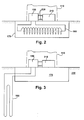
FIG. 1 is a front view illustration of an exemplary wind turbine with a cross sectional illustration of the foundation and geothermal heating and cooling system according to one aspect of the present invention. -
FIG. 2 is a partial, cross sectional illustration of an exemplary wind turbine with a cross sectional illustration of the foundation and geothermal heating and cooling system according to one aspect of the present invention. -
FIG. 3 is a partial, cross sectional illustration of an exemplary wind turbine with a cross sectional illustration of the foundation and geothermal heating and cooling system according to one aspect of the present invention. - A horizontal axis wind turbine (HAWT), hereafter "wind turbine", 100 is illustrated in
Fig.1 . However, the present invention can be employed with any wind turbine, including, but not limited to vertical axis wind turbines. Thewind turbine 100 may include atubular tower 110, which is often manufactured of steel. Thetower 110 may be erected by stacking multiple tower segments on top of each other. Thetower 110 supports the weight of thenacelle 120,blades 130 andhub 140. Towers may also be of the lattice (or truss) type, and tubular towers may alternatively be formed of concrete or other suitable materials. Thenacelle 120 typically houses the drive train (e.g., gearbox, shafts, couplings, generator, etc.), as well as the main frame (also called bedplate) and yaw drives. Other items such as the control electronics may be housed within thenacelle 120 or intower 110. Typically, thenacelle 120 has an outer skin that is comprised of a lightweight material such as fiberglass or a graphite composite. The main function of the nacelle skin is to protect the contents from the elements (e.g., rain, ice, snow, etc.). - The
blades 130 are connected to thehub 140, and the hub may contain a pitch control mechanism to control the pitch angle of each blade. Typically, three blades are employed in most commercial wind turbines. However, one, two, or four or more blades could be employed as well. The blades convert the kinetic energy of the wind into mechanical energy by rotating a low speed shaft. Blades may be manufactured from fiberglass, graphite composites, fiberglass reinforced plastics or wood/epoxy laminates, or other suitable materials. The low speed shaft is connected to thehub 140 typically via a bolted flange coupling. - Various control and power electronics can be located at the base of
tower 110. The control electronics can control the various operating modes (e.g., blade pitch angle, start-up or shut-down sequence, etc.) ofwind turbine 100. The power electronics may include transformers and converters, and these power electronics are used to transform the voltage output by the generator into the proper form for transmission onto the electrical grid. While having the controls at the base of the tower is one typical implementation, it is not the only possible configuration. The controls could also be placed in the nacelle or in other sections of the tower. In other implementations, the control or power electronics could be housed outside butnearby wind turbine 100. The geo-thermal heating or cooling system, as embodied by the present invention, can also be adapted for use on components in locations other than the tower base via the proper pipe and hose routing and connection. - Typically, a radiator is used to water-cool the control and power electronics. The heat extracted is then dumped to the air. This approach may work well when the electronics need to be cooled and the ambient air temperature is cold, but is often less than satisfactory at warmer ambient temperatures. For example, when the ambient air temperature is near 38 degrees C (100 degrees F) the amount of heat that can be dumped to the air is very limited. Conversely, when the ambient air temperature is very cold, the electronics may need to be kept above freezing (0 degrees C). Current systems would need to incorporate a separate heater for this purpose, and the energy taken from the generator can reduce the efficiency and power output of the wind turbine.
- Most commercial, land based wind turbines require a large foundation (e.g., reinforced concrete). This foundation is dug into the earth and extends from about eight to about 15 feet deep into the soil, which is below the frost line. In some cases, the foundation may go deeper than 15 feet. The soil temperature, below the frost line, is relatively constant (e.g., 15-25 degrees C). This temperature range is relatively cool compared to hot summer air (in some locations), and relatively warm compared to cold winter air (in some locations). According to aspects of the present invention, a geothermal heating and cooling system can take advantage of this relatively constant ground temperature and use it to heat the wind turbine's electronics in the winter, and cool the electronics in the summer.
- Referring to
Figs. 1-3 , thegeothermal system 150 can have one section located withintower 110 and have another section comprised of piping 160 located within the wind turbine'sfoundation 170. Theportion 150 insidetower 110 can include a heat exchanger (not shown) to exchange heat with various power andcontrol electronics 210. The power andcontrol electronics 210 are typically located insidetower 110 at the base thereof, but the electronics may also be located higher in the tower, in thenacelle 120, or even outsidetower 110. - Piping 220 may be routed from the heat exchanger located in
system 150 to theelectronics 210. If there are electronics or other units to be heated or cooled the piping could be routed up intotower 110 or even intonacelle 120. For example, the generator (not shown), which is located innacelle 120, can be cooled by routing piping 220 uptower 110 and intonacelle 120. In this manner any unit or device needing to be heated or cooled, within the nacelle, could be reached by appropriately routingpiping 220. - Typically, a pump (not shown) is included with
system 150 for pumping a thermal transfer medium (e.g., water, antifreeze, oil, etc.) through a distribution system (e.g., piping 220 and 160). The pump feeds the thermal transfer medium through the units and components to be heated or cooled (e.g. a frequency converter, a transformer, controller, generator, gear box, etc.) for cooling these units or components directly or indirectly. -
Fig. 2 illustrates one embodiment of the present invention where thegeothermal piping 160 is contained withinfoundation 170. In other embodiments, the piping could be contained in the surrounding soil or in trenches. Typically,foundations 170 are greater than about 10 feet deep and the lower portion of the foundation is well below the frost line. The foundation, typically reinforced concrete, is also a large thermal mass that can function as a heat source or heat sink. In warmer seasons, such as the summer, the concrete foundation can absorb a large amount of heat generated by the various power and control electronics. In colder seasons, such as the winter, the lower part of the foundation is below the frost line, and can be used as a heat source to maintain the temperature of the various power and control electronics above freezing. -
Fig. 3 illustrates another embodiment where thegeothermal piping 160 extends into the earth near the wind turbine. The piping 160 is shown to the side of the wind turbine'sfoundation 170. However, the piping could also be arranged to encircle all or a portion of the wind turbine's foundation. Theearth 330 functions as an excellent heat source or heat sink. - It is common to have trenches formed in the earth between turbines or between turbines and power or control substations. The trenches can contain various cables for power transmission and control signals. These trenches could also be used to house
geothermal piping 160. In some embodiments, one trench could be used to contain geothermal piping for multiple turbines. - The use of one heat exchanger has been described, but it would be possible to use multiple heat exchangers. Multiple heat exchangers could be located within the same or different parts of
wind turbine 100, and be connected to the samegeothermal piping 160 or to separate and distinct loops. -
Geothermal piping 160 could be arranged in a closed loop field, open loop field, horizontal closed loop field, vertical closed loop field, slinky closed loop field, or as a closed pond loop. A closed pond loop could be used when the wind turbine is near a pond, lake or other water source. The geothermal piping could be placed near the bottom of the water source and the water would then act as the heat source or heat sink. - The various embodiments have been described in conjunction with a horizontal axis wind turbine (HAWT), but it is to be understood that various aspects of the invention could also be applied to vertical axis wind turbines (VAWT) as well. While various embodiments are described herein, it will be appreciated from the specification that various combinations of elements, variations or improvements therein may be made, and are within the scope of the invention.
Claims (10)
- A wind turbine (100) comprising:a tower (110);a nacelle (120) rotatably supported by said tower (110);at least one unit (210) to be heated or cooled and arranged in, at least one of said tower and said nacelle;at least one thermal transfer system (150) located inside, at least one of said tower (110) and said nacelle (120), said at least one thermal transfer system (150) configured to be geothermally heated or cooled;and a thermal circuit (160) providing flow communication between said at least one unit (210) to be heated or cooled and said at least one thermal transfer system (150), said thermal circuit (160) containing a heat transfer medium flowing between said at least one unit (210) and said at least one thermal transfer system (150) for facilitating heating or cooling said at least one unit (210).
- A wind turbine (100) comprising:a foundation (170);a tower (110) supported by said foundation (170);at least one unit (210) to be heated or cooled;at least one thermal transfer system (150), at least a portion of said at least one thermal transfer system located within or near said wind turbine, said thermal transfer system comprising a thermal circuit (160) containing a heat transfer medium, at least a portion of said thermal circuit extending into at least one of, said foundation (170) and earth (330) near said foundation (170);wherein, said thermal transfer system transfers heat between said at least one unit to be heated or cooled, and at least one of said foundation (170) and said earth (330).
- The wind turbine (100) according to any of the preceding claims, wherein a portion of said thermal circuit (160) is contained within a foundation (170) of said wind turbine.
- The wind turbine (100) according to any of the preceding claims, wherein a portion of said thermal circuit (160) is contained within the earth near said wind turbine.
- The wind turbine (100) according to any of the preceding claims, wherein a portion of said thermal circuit (160) is contained within a trench, said trench located near said wind turbine.
- The wind turbine (100) according to any of the preceding claims, wherein said thermal circuit (160) is a closed loop.
- The wind turbine (100) according to any of the preceding claims, wherein said thermal transfer system (150) comprises at least one pump for pumping the heat transfer medium from said at least one unit (210) to said at least one thermal transfer system (150).
- The wind turbine (100) according to any of the preceding claims, wherein the thermal transfer system (150) is a geothermal system.
- The wind turbine (100) according to any of the preceding claims, wherein said thermal circuit (160) is substantially contained within the foundation (170) of said wind turbine.
- The wind turbine (100) according to any of the preceding claims, wherein said thermal circuit (160) is substantially contained within the earth (330) near said wind turbine.
Applications Claiming Priority (1)
| Application Number | Priority Date | Filing Date | Title |
|---|---|---|---|
| US11/871,196 US20090094981A1 (en) | 2007-10-12 | 2007-10-12 | Wind turbine geothermal heating and cooling system |
Publications (1)
| Publication Number | Publication Date |
|---|---|
| EP2060787A2 true EP2060787A2 (en) | 2009-05-20 |
Family
ID=40497676
Family Applications (1)
| Application Number | Title | Priority Date | Filing Date |
|---|---|---|---|
| EP08165567A Withdrawn EP2060787A2 (en) | 2007-10-12 | 2008-10-01 | Wind turbine geothermal heating and cooling system |
Country Status (5)
| Country | Link |
|---|---|
| US (1) | US20090094981A1 (en) |
| EP (1) | EP2060787A2 (en) |
| CN (1) | CN101408150A (en) |
| AU (1) | AU2008229916A1 (en) |
| CA (1) | CA2639768A1 (en) |
Cited By (1)
| Publication number | Priority date | Publication date | Assignee | Title |
|---|---|---|---|---|
| CN101915217A (en) * | 2010-08-07 | 2010-12-15 | 葛洲坝集团电力有限责任公司 | Solar energy and geothermal energy co-generation system |
Families Citing this family (34)
| Publication number | Priority date | Publication date | Assignee | Title |
|---|---|---|---|---|
| AU2007315391B2 (en) * | 2006-11-03 | 2011-06-30 | Vestas Wind Systems A/S | A wind energy converter, a wind turbine foundation, a method and use of a wind turbine foundation |
| CA2667625A1 (en) * | 2006-11-03 | 2008-05-08 | Vestas Wind Systems A/S | A wind energy converter, a method and use hereof |
| IT1390758B1 (en) | 2008-07-23 | 2011-09-23 | Rolic Invest Sarl | WIND GENERATOR |
| IT1391939B1 (en) | 2008-11-12 | 2012-02-02 | Rolic Invest Sarl | WIND GENERATOR |
| IT1391770B1 (en) | 2008-11-13 | 2012-01-27 | Rolic Invest Sarl | WIND GENERATOR FOR THE GENERATION OF ELECTRICITY |
| IT1392804B1 (en) | 2009-01-30 | 2012-03-23 | Rolic Invest Sarl | PACKAGING AND PACKAGING METHOD FOR POLE OF WIND GENERATORS |
| IT1393937B1 (en) | 2009-04-09 | 2012-05-17 | Rolic Invest Sarl | WIND TURBINE |
| IT1393707B1 (en) | 2009-04-29 | 2012-05-08 | Rolic Invest Sarl | WIND POWER PLANT FOR THE GENERATION OF ELECTRICITY |
| IT1394723B1 (en) | 2009-06-10 | 2012-07-13 | Rolic Invest Sarl | WIND POWER PLANT FOR THE GENERATION OF ELECTRICITY AND ITS CONTROL METHOD |
| IT1395148B1 (en) | 2009-08-07 | 2012-09-05 | Rolic Invest Sarl | METHOD AND APPARATUS FOR ACTIVATION OF AN ELECTRIC MACHINE AND ELECTRIC MACHINE |
| US20100139736A1 (en) * | 2009-09-16 | 2010-06-10 | General Electric Company | Geothermal heating and cooling management system |
| US7837126B2 (en) * | 2009-09-25 | 2010-11-23 | General Electric Company | Method and system for cooling a wind turbine structure |
| US7880320B2 (en) * | 2009-10-30 | 2011-02-01 | General Electric Company | System, device, and method for controlling a wind turbine using seasonal parameters |
| IT1397081B1 (en) | 2009-11-23 | 2012-12-28 | Rolic Invest Sarl | WIND POWER PLANT FOR THE GENERATION OF ELECTRICITY |
| US20110132571A1 (en) * | 2009-12-04 | 2011-06-09 | General Electric Company | Systems relating to geothermal energy and the operation of gas turbine engines |
| JP5318740B2 (en) * | 2009-12-11 | 2013-10-16 | 株式会社日立製作所 | Offshore windmill |
| JP5001999B2 (en) * | 2009-12-16 | 2012-08-15 | 三菱重工業株式会社 | Wind power generator |
| IT1398060B1 (en) | 2010-02-04 | 2013-02-07 | Wilic Sarl | PLANT AND METHOD OF COOLING OF AN ELECTRIC GENERATOR OF AN AIR SPREADER, AND AIRCONDITIONER INCLUDING SUCH A COOLING PLANT |
| US20110215585A1 (en) * | 2010-03-03 | 2011-09-08 | Richard Caires | Clear wind tower system technology |
| IT1399201B1 (en) | 2010-03-30 | 2013-04-11 | Wilic Sarl | AEROGENERATOR AND METHOD OF REMOVING A BEARING FROM A AIRCONDITIONER |
| US20110133472A1 (en) * | 2010-04-20 | 2011-06-09 | Joerg Middendorf | Wind Turbine, Nacelle, And Method Of Assembling Wind Turbine |
| IT1399511B1 (en) | 2010-04-22 | 2013-04-19 | Wilic Sarl | ELECTRIC GENERATOR FOR A VENTILATOR AND AEROGENER EQUIPPED WITH THIS ELECTRIC GENERATOR |
| US8529202B2 (en) * | 2010-10-12 | 2013-09-10 | General Electric Company | System and method for turbine compartment ventilation |
| US20120090808A1 (en) * | 2010-10-18 | 2012-04-19 | Alcatel-Lucent Usa, Incorporated | Liquid cooling of remote or off-grid electronic enclosures |
| JP5449235B2 (en) * | 2011-02-25 | 2014-03-19 | 三菱重工業株式会社 | Wind power generator |
| ITMI20110377A1 (en) | 2011-03-10 | 2012-09-11 | Wilic Sarl | ROTARY ELECTRIC MACHINE FOR AEROGENERATOR |
| ITMI20110378A1 (en) | 2011-03-10 | 2012-09-11 | Wilic Sarl | ROTARY ELECTRIC MACHINE FOR AEROGENERATOR |
| ITMI20110375A1 (en) | 2011-03-10 | 2012-09-11 | Wilic Sarl | WIND TURBINE |
| US9091249B2 (en) * | 2012-06-05 | 2015-07-28 | Games Innovation & Technology, S.L. | Integrated cooling and climate control system for an offshore wind turbine |
| ES2539643B1 (en) * | 2013-10-21 | 2016-01-26 | Adolfo GONZÁLEZ PÉREZ | Autonomous wind turbine with energy accumulation and applications |
| NL2016384B1 (en) * | 2016-03-08 | 2017-09-27 | Univ Delft Tech | Wind turbine. |
| CN112654783A (en) * | 2018-06-18 | 2021-04-13 | 零意技术有限责任公司 | Wind turbine, heat pump, energy storage and heat transport system and method |
| CN112728625A (en) * | 2020-12-31 | 2021-04-30 | 王晶 | Fireproof electric floor heating structure |
| CN113530771B (en) * | 2021-08-30 | 2023-06-27 | 上海凯士比泵有限公司 | External circulating cooling system of wind generating set by utilizing underground water source |
Family Cites Families (16)
| Publication number | Priority date | Publication date | Assignee | Title |
|---|---|---|---|---|
| US4448238A (en) * | 1980-09-11 | 1984-05-15 | Singleton Jr Lewis | Heat exchange system and process for heating and cooling using geothermal energy |
| US4920757A (en) * | 1988-08-18 | 1990-05-01 | Jimmy Gazes | Geothermal heating and air conditioning system |
| US4993483A (en) * | 1990-01-22 | 1991-02-19 | Charles Harris | Geothermal heat transfer system |
| DK23391D0 (en) * | 1991-02-12 | 1991-02-12 | Soerensen Jens Richard | WINDOW FOR SELF-SUPPLY AND STORAGE OF ENERGY |
| US5216577A (en) * | 1991-10-25 | 1993-06-01 | Comtronics Enclosures Corporation | Stable thermal enclosure for outdoor electronics |
| US5388419A (en) * | 1993-04-23 | 1995-02-14 | Maritime Geothermal Ltd. | Staged cooling direct expansion geothermal heat pump |
| DE19816483C2 (en) * | 1998-04-14 | 2003-12-11 | Aloys Wobben | Wind turbine |
| EP1185790B1 (en) * | 1999-05-07 | 2004-10-27 | NEG Micon A/S | An offshore wind turbine with liquid-cooling |
| ATE250721T1 (en) * | 1999-07-14 | 2003-10-15 | Aloys Wobben | WIND TURBINE WITH A CLOSED COOLING CIRCUIT |
| DE10324228B4 (en) * | 2003-05-28 | 2006-02-16 | Rittal Gmbh & Co. Kg | Cooling device for an offshore wind turbine |
| US7048037B2 (en) * | 2003-12-09 | 2006-05-23 | Mcnair Edward F | Geothermal heating and/or cooling apparatus and method of using same |
| US20060059911A1 (en) * | 2004-09-17 | 2006-03-23 | Daniel Shichman | Space heating and cooling system having a co-generator drive a geothermal connected heat pump |
| US7443066B2 (en) * | 2005-07-29 | 2008-10-28 | General Electric Company | Methods and apparatus for cooling wind turbine generators |
| US7235895B2 (en) * | 2005-10-13 | 2007-06-26 | General Electric Company | Method and apparatus for gravity induced thermal energy dissipation |
| US7124584B1 (en) * | 2005-10-31 | 2006-10-24 | General Electric Company | System and method for heat recovery from geothermal source of heat |
| US7168251B1 (en) * | 2005-12-14 | 2007-01-30 | General Electric Company | Wind energy turbine |
-
2007
- 2007-10-12 US US11/871,196 patent/US20090094981A1/en not_active Abandoned
-
2008
- 2008-09-25 CA CA002639768A patent/CA2639768A1/en not_active Abandoned
- 2008-10-01 EP EP08165567A patent/EP2060787A2/en not_active Withdrawn
- 2008-10-02 AU AU2008229916A patent/AU2008229916A1/en not_active Abandoned
- 2008-10-10 CN CNA2008101693948A patent/CN101408150A/en active Pending
Cited By (1)
| Publication number | Priority date | Publication date | Assignee | Title |
|---|---|---|---|---|
| CN101915217A (en) * | 2010-08-07 | 2010-12-15 | 葛洲坝集团电力有限责任公司 | Solar energy and geothermal energy co-generation system |
Also Published As
| Publication number | Publication date |
|---|---|
| US20090094981A1 (en) | 2009-04-16 |
| CN101408150A (en) | 2009-04-15 |
| CA2639768A1 (en) | 2009-04-12 |
| AU2008229916A1 (en) | 2009-04-30 |
Similar Documents
| Publication | Publication Date | Title |
|---|---|---|
| EP2060787A2 (en) | Wind turbine geothermal heating and cooling system | |
| US8875511B2 (en) | Geothermal wind system | |
| CN104246217B (en) | Hybrid system for generating electricity from solar thermal and wind energy | |
| US9574551B2 (en) | Power tower—system and method of using air flow generated by geothermal generated heat to drive turbines generators for the generation of electricity | |
| US5694774A (en) | Solar energy powerplant | |
| US20090212560A1 (en) | Heating System, Wind Turbine Or Wind Park, Method For Utilizing Surplus Heat Of One Or More Wind Turbine Components And Use Hereof | |
| US20120085093A1 (en) | Hybrid renewable energy system having underground heat storage apparatus | |
| US20110089701A1 (en) | Methods and apparatus for generating electrical energy based on waste air flow | |
| CN101888148A (en) | Cooling system and wind turbine incorporating the cooling system | |
| JP2003504562A (en) | Wind power facility with closed cooling circuit | |
| CA2699273A1 (en) | Renewable energy fluid pump to fluid-based energy generation | |
| CN102072095A (en) | Wind turbine with direct-connected variable speed blower | |
| CN210033731U (en) | Wind driven generator with ice melting function | |
| CN101334221A (en) | Huge energy wind power heat pump and thermal power plant combined production device | |
| CN112483322A (en) | Gravity wind power generation device | |
| Mahmoud et al. | Applications of wind energy | |
| CN111102133A (en) | A solar greenhouse wind-induced heat energy storage device | |
| US20090315333A1 (en) | Production of electricity from low-temperature energy sources | |
| JP3252680U (en) | Agricultural greenhouse heating system using unused heat from a power-generating wind turbine | |
| KR102953508B1 (en) | Wind power generation system using low pressure rising air currents | |
| Smith et al. | Cold climate energy production | |
| KR102429086B1 (en) | Electric-hydraulic cogeneration system with wind | |
| KR20100000001A (en) | The cyclone wind power station or system which can produce electricity by sola heat | |
| Juraboevich et al. | STUDY OF WIND ENERGY POTENTIAL IN MOUNTAINOUS AND FOOTHILL REGIONS OF THE REPUBLIC OF UZBEKISTAN | |
| JP2023095534A (en) | Agricultural greenhouse heating system using unused heat from wind turbines for power generation as a heat source |
Legal Events
| Date | Code | Title | Description |
|---|---|---|---|
| PUAI | Public reference made under article 153(3) epc to a published international application that has entered the european phase |
Free format text: ORIGINAL CODE: 0009012 |
|
| AK | Designated contracting states |
Kind code of ref document: A2 Designated state(s): AT BE BG CH CY CZ DE DK EE ES FI FR GB GR HR HU IE IS IT LI LT LU LV MC MT NL NO PL PT RO SE SI SK TR |
|
| AX | Request for extension of the european patent |
Extension state: AL BA MK RS |
|
| STAA | Information on the status of an ep patent application or granted ep patent |
Free format text: STATUS: THE APPLICATION IS DEEMED TO BE WITHDRAWN |
|
| 18D | Application deemed to be withdrawn |
Effective date: 20110503 |