EP2060781A2 - Engine control apparatus and method - Google Patents
Engine control apparatus and method Download PDFInfo
- Publication number
- EP2060781A2 EP2060781A2 EP08168930A EP08168930A EP2060781A2 EP 2060781 A2 EP2060781 A2 EP 2060781A2 EP 08168930 A EP08168930 A EP 08168930A EP 08168930 A EP08168930 A EP 08168930A EP 2060781 A2 EP2060781 A2 EP 2060781A2
- Authority
- EP
- European Patent Office
- Prior art keywords
- discharge device
- electric discharge
- electrodes
- internal combustion
- voltage
- Prior art date
- Legal status (The legal status is an assumption and is not a legal conclusion. Google has not performed a legal analysis and makes no representation as to the accuracy of the status listed.)
- Granted
Links
- 238000000034 method Methods 0.000 title claims description 14
- 238000002485 combustion reaction Methods 0.000 claims abstract description 116
- 239000000446 fuel Substances 0.000 claims abstract description 108
- 239000000203 mixture Substances 0.000 claims abstract description 53
- 230000006835 compression Effects 0.000 claims description 81
- 238000007906 compression Methods 0.000 claims description 81
- 239000003989 dielectric material Substances 0.000 claims description 26
- 230000004888 barrier function Effects 0.000 claims description 21
- 238000010891 electric arc Methods 0.000 claims description 10
- 230000007246 mechanism Effects 0.000 description 48
- 230000020169 heat generation Effects 0.000 description 21
- 238000010586 diagram Methods 0.000 description 18
- 230000001965 increasing effect Effects 0.000 description 16
- 230000007423 decrease Effects 0.000 description 8
- 230000006870 function Effects 0.000 description 8
- 230000036961 partial effect Effects 0.000 description 8
- 230000002829 reductive effect Effects 0.000 description 8
- 230000000694 effects Effects 0.000 description 7
- 238000002347 injection Methods 0.000 description 7
- 239000007924 injection Substances 0.000 description 7
- 210000001331 nose Anatomy 0.000 description 7
- 150000002500 ions Chemical class 0.000 description 5
- 230000000052 comparative effect Effects 0.000 description 4
- 239000011810 insulating material Substances 0.000 description 4
- 230000010355 oscillation Effects 0.000 description 4
- 238000007254 oxidation reaction Methods 0.000 description 4
- 230000008859 change Effects 0.000 description 3
- 238000010494 dissociation reaction Methods 0.000 description 3
- 230000005593 dissociations Effects 0.000 description 3
- 230000000977 initiatory effect Effects 0.000 description 3
- 230000009471 action Effects 0.000 description 2
- 239000003990 capacitor Substances 0.000 description 2
- 238000006243 chemical reaction Methods 0.000 description 2
- 239000004020 conductor Substances 0.000 description 2
- 230000003247 decreasing effect Effects 0.000 description 2
- 239000007789 gas Substances 0.000 description 2
- 238000003780 insertion Methods 0.000 description 2
- 230000037431 insertion Effects 0.000 description 2
- 230000000670 limiting effect Effects 0.000 description 2
- 230000007935 neutral effect Effects 0.000 description 2
- 239000002245 particle Substances 0.000 description 2
- 238000011160 research Methods 0.000 description 2
- 102100027617 DNA/RNA-binding protein KIN17 Human genes 0.000 description 1
- 101100398255 Homo sapiens KIN gene Proteins 0.000 description 1
- 230000005540 biological transmission Effects 0.000 description 1
- 230000015556 catabolic process Effects 0.000 description 1
- 230000001010 compromised effect Effects 0.000 description 1
- 238000007796 conventional method Methods 0.000 description 1
- 230000009977 dual effect Effects 0.000 description 1
- 238000005516 engineering process Methods 0.000 description 1
- 230000006872 improvement Effects 0.000 description 1
- 230000001939 inductive effect Effects 0.000 description 1
- 238000009413 insulation Methods 0.000 description 1
- 238000012986 modification Methods 0.000 description 1
- 230000004048 modification Effects 0.000 description 1
- 238000012545 processing Methods 0.000 description 1
- 239000011435 rock Substances 0.000 description 1
Images











Classifications
-
- F—MECHANICAL ENGINEERING; LIGHTING; HEATING; WEAPONS; BLASTING
- F02—COMBUSTION ENGINES; HOT-GAS OR COMBUSTION-PRODUCT ENGINE PLANTS
- F02P—IGNITION, OTHER THAN COMPRESSION IGNITION, FOR INTERNAL-COMBUSTION ENGINES; TESTING OF IGNITION TIMING IN COMPRESSION-IGNITION ENGINES
- F02P23/00—Other ignition
- F02P23/04—Other physical ignition means, e.g. using laser rays
-
- F—MECHANICAL ENGINEERING; LIGHTING; HEATING; WEAPONS; BLASTING
- F02—COMBUSTION ENGINES; HOT-GAS OR COMBUSTION-PRODUCT ENGINE PLANTS
- F02D—CONTROLLING COMBUSTION ENGINES
- F02D41/00—Electrical control of supply of combustible mixture or its constituents
- F02D41/30—Controlling fuel injection
- F02D41/3011—Controlling fuel injection according to or using specific or several modes of combustion
- F02D41/3017—Controlling fuel injection according to or using specific or several modes of combustion characterised by the mode(s) being used
- F02D41/3035—Controlling fuel injection according to or using specific or several modes of combustion characterised by the mode(s) being used a mode being the premixed charge compression-ignition mode
- F02D41/3041—Controlling fuel injection according to or using specific or several modes of combustion characterised by the mode(s) being used a mode being the premixed charge compression-ignition mode with means for triggering compression ignition, e.g. spark plug
-
- F—MECHANICAL ENGINEERING; LIGHTING; HEATING; WEAPONS; BLASTING
- F02—COMBUSTION ENGINES; HOT-GAS OR COMBUSTION-PRODUCT ENGINE PLANTS
- F02M—SUPPLYING COMBUSTION ENGINES IN GENERAL WITH COMBUSTIBLE MIXTURES OR CONSTITUENTS THEREOF
- F02M27/00—Apparatus for treating combustion-air, fuel, or fuel-air mixture, by catalysts, electric means, magnetism, rays, sound waves, or the like
- F02M27/04—Apparatus for treating combustion-air, fuel, or fuel-air mixture, by catalysts, electric means, magnetism, rays, sound waves, or the like by electric means, ionisation, polarisation or magnetism
- F02M27/042—Apparatus for treating combustion-air, fuel, or fuel-air mixture, by catalysts, electric means, magnetism, rays, sound waves, or the like by electric means, ionisation, polarisation or magnetism by plasma
-
- F—MECHANICAL ENGINEERING; LIGHTING; HEATING; WEAPONS; BLASTING
- F02—COMBUSTION ENGINES; HOT-GAS OR COMBUSTION-PRODUCT ENGINE PLANTS
- F02P—IGNITION, OTHER THAN COMPRESSION IGNITION, FOR INTERNAL-COMBUSTION ENGINES; TESTING OF IGNITION TIMING IN COMPRESSION-IGNITION ENGINES
- F02P3/00—Other installations
- F02P3/01—Electric spark ignition installations without subsequent energy storage, i.e. energy supplied by an electrical oscillator
-
- F—MECHANICAL ENGINEERING; LIGHTING; HEATING; WEAPONS; BLASTING
- F02—COMBUSTION ENGINES; HOT-GAS OR COMBUSTION-PRODUCT ENGINE PLANTS
- F02P—IGNITION, OTHER THAN COMPRESSION IGNITION, FOR INTERNAL-COMBUSTION ENGINES; TESTING OF IGNITION TIMING IN COMPRESSION-IGNITION ENGINES
- F02P9/00—Electric spark ignition control, not otherwise provided for
- F02P9/002—Control of spark intensity, intensifying, lengthening, suppression
- F02P9/007—Control of spark intensity, intensifying, lengthening, suppression by supplementary electrical discharge in the pre-ionised electrode interspace of the sparking plug, e.g. plasma jet ignition
Definitions
- the present invention generally relates to an engine control apparatus and method and particularly, but not exclusively, to an apparatus and method for controlling an internal combustion engine comprising an electric discharge device. Aspects of the invention relate to an apparatus, to a structure, to an engine, to a method and to a vehicle
- An electric discharge device has been proposed for an internal combustion engine in which the air-fuel mixture is ignited in an assisted manner by a sparkplug.
- radicals are generated in a cylinder and the auto-ignition properties of the air-fuel mixture are improved (see, Japanese Laid-Open Patent Application No. 2001-20842 ).
- the radicals tend to induce oxidation reactions (i.e., combustion), and the oxidation reactions (combustion) tend to become chain reactions. Therefore, when radicals are generated in the cylinder, the auto-ignition properties of the air-fuel mixture are improved.
- a sparkplug can be used to generate radicals in the cylinder.
- spark ignition is a thermal plasma discharge
- the efficiency of radical generation is low even if spark ignition is induced by a sparkplug as in the conventional apparatus previously described.
- the amount of radicals generated is limited. It is therefore believed that the effects of improving the auto-ignition properties are small.
- Embodiments of the invention may provide a control apparatus and a control method for an internal combustion engine that enables the auto-ignition properties of the air-fuel mixture to be improved in comparison with conventional internal combustion engines.
- Other aims and advantages of the invention will become apparent from the following description, claims and drawings.
- an engine control apparatus comprising an electric discharge device including a first electrode and a second electrode arranged opposite the first electrode to produce radicals within a combustion chamber of an internal combustion engine by a non-equilibrium plasma discharge that is generated between the electrodes before auto-ignition of the air-fuel mixture occurs, a voltage application device operatively coupled to the first electrode for applying a voltage between the first and second electrodes to generate the non-equilibrium plasma between the first and second electrodes, a fuel supplying device arranged to form an air-fuel mixture inside the combustion chamber and a control unit operatively couple to the electric discharge device to set a discharge start timing of the electric discharge device to occur during an intake stroke of the internal combustion engine.
- control unit sets the discharge start timing of the electric discharge device to occur after an intake valve opens in the internal combustion engine.
- control unit sets the discharge start timing of the electric discharge device to occur after an exhaust valve opens in the internal combustion engine.
- control unit sets the discharge start timing of the electric discharge device to occur before an intake valve closes in the internal combustion engine.
- control unit sets the discharge start timing of the electric discharge device to occur before an intake valve closes in the internal combustion engine.
- control unit sets the discharge start timing of the electric discharge device to occur before an intake valve closes in the internal combustion engine.
- the electric discharge device is a short pulse application discharge device that applies a short pulse voltage across the first electrode and the second electrode such that the voltage stops before an arc discharge occurs, and the radicals improve an auto-ignition property of the air-fuel mixture during a compression stroke due to the non-equilibrium plasma discharge generated between the electrodes.
- the electric discharge device is a short pulse application discharge device that applies a short pulse voltage across the first electrode and the second electrode such that the voltage stops before an arc discharge occurs, and the radicals improve an auto-ignition property of the air-fuel mixture during a compression stroke due to the non-equilibrium plasma discharge generated between the electrodes.
- the electric discharge device is a short pulse application discharge device that applies a short pulse voltage across the first electrode and the second electrode such that the voltage stops before an arc discharge occurs, and the radicals improve an auto-ignition property of the air-fuel mixture during a compression stroke due to the non-equilibrium plasma discharge generated between the electrodes.
- the electric discharge device is a barrier discharge device in which a dielectric material is formed on one of the first and second electrodes such that when a voltage is applied across the first and second electrodes the radicals improve an auto-ignition property of an air-fuel mixture during a compression stroke due to a barrier discharge generated between the one of the first and second electrodes with dielectric material and the other of the first and second electrodes.
- the electric discharge device is a barrier discharge device in which a dielectric material is formed on one of the first and second electrodes such that when a voltage is applied across the first and second electrodes the radicals improve an auto-ignition property of an air-fuel mixture during a compression stroke due to a barrier discharge generated between the one of the first and second electrodes with dielectric material and the other of the first and second electrodes.
- the electric discharge device is a barrier discharge device in which a dielectric material is formed on one of the first and second electrodes such that when a voltage is applied across the first and second electrodes the radicals improve an auto-ignition property of an air-fuel mixture during a compression stroke due to a barrier discharge generated between the one of the first and second electrodes with dielectric material and the other of the first and second electrodes.
- an engine control apparatus comprising electric discharge means for producing radicals within a combustion chamber of an internal combustion engine by a non-equilibrium plasma discharge that is generated before auto-ignition of the air-fuel mixture occurs, means for applying voltage to electric discharge means to generate the non-equilibrium plasma between the first and second electrodes, means for forming an air-fuel mixture inside the combustion chamber and means for setting a discharge start timing of the electric discharge means to occur during an intake stroke of the internal combustion engine.
- an engine control method comprising applying a voltage between first and second electrodes of an electric discharge device to produce radicals within a combustion chamber of an internal combustion engine by a non-equilibrium plasma discharge that is generated between the first and second electrodes before auto-ignition of the air-fuel mixture occurs, forming an air-fuel mixture inside the combustion chamber and controlling the electric discharge device to set a discharge start timing of the electric discharge device to occur during an intake stroke of the internal combustion engine.
- controlling of the electric discharge device further includes setting the discharge start timing of the electric discharge device to occur after an intake valve opens in the internal combustion engine.
- controlling of the electric discharge device further includes setting the discharge start timing of the electric discharge device to occur after an exhaust valve opens in the internal combustion engine.
- controlling of the electric discharge device further includes setting the discharge start timing of the electric discharge device to occur before an intake valve closes in the internal combustion engine.
- an engine control apparatus may comprise an electric discharge device, a voltage application device, a fuel supplying device, and a control unit.
- the electric discharge device includes a first electrode and a second electrode.
- the second electrode is arranged opposite the first electrode to produce radicals within a combustion chamber of an internal combustion engine by a non-equilibrium plasma discharge that is generated between the electrodes before auto-ignition of the air-fuel mixture occurs.
- the voltage application device is operatively coupled to the first electrode for applying a voltage between the first and second electrodes to generate the non-equilibrium plasma between the first and second electrodes.
- the fuel supplying device forms an air-fuel mixture inside the combustion chamber.
- the control unit is operatively coupled to the electric discharge device to set a discharge start timing of the electric discharge device to occur during an intake stroke of the internal combustion engine.
- spark ignition generates radicals (chemically active species which are in a state of molecular dissociation induced by the collision of high-energy electrons with fuel or air molecules, and which promote ignition of an air-fuel mixture) in a cylinder and in which the auto-ignition properties (compression ignition properties) of the air-fuel mixture are improved.
- radicals chemically active species which are in a state of molecular dissociation induced by the collision of high-energy electrons with fuel or air molecules, and which promote ignition of an air-fuel mixture
- auto-ignition properties compression ignition properties
- spark ignition involves a thermal plasma discharge.
- a thermal plasma discharge kinetic energy is adequately exchanged among electrons, ions, and molecules. The result is an establishment of a state of thermal equilibrium in which the electron energy, the ion energy, and the neutral particle energy are in equilibrium with each other.
- Radicals are chemically active species which are in a state of molecular dissociation induced by collisions of high-energy electrons with fuel or air molecules, and which promote ignition of the air-fuel mixture.
- spark ignition energy is also imparted to ions and molecules which do not contribute to the generation of radicals, and the efficiency of conversion of input energy to electron energy is low. When the input energy is increased in order to increase the amount of radicals, there is a possibility that the electrodes will melt. Therefore, it is difficult to increase the amount of radicals.
- a non-equilibrium plasma discharge is advantageous.
- a thermally non-equilibrium state is achieved in which the electron temperature (electron energy) alone is extremely high (more specifically, the electron energy is much higher than both the ion energy and the neutral particle energy, which is substantially equal to the ion energy), and the efficiency of converting input energy to electron energy is high.
- Heat loss is small in a non-equilibrium plasma discharge because the gas temperature is not increased. The danger that the electrodes will melt is also small.
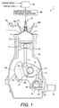
- FIG. 1 a simplified schematic cross-sectional view of a portion of a multi-link engine 1 is illustrated that contains an electric discharge device in accordance with a first embodiment.
- the multi-link engine 1 utilizes a non-equilibrium plasma discharge function to improve the auto-ignition properties of the multi-link engine 1.
- the engine 1 is provided with a non-equilibrium plasma discharge device 70.
- the non-equilibrium plasma discharge device 70 is provided between an intake port 60a and an exhaust port 60b, substantially in the center of a combustion chamber of a cylinder head.
- the non-equilibrium plasma discharge device 70 generates radicals by means of a non-equilibrium plasma discharge.
- the non-equilibrium plasma discharge device 70 is also capable of igniting an air-fuel mixture through non-equilibrium plasma discharge when the engine is operating at a comparatively high load (when the air-to-fuel ratio of the air-fuel mixture is comparatively rich).
- the detailed structure of the non-equilibrium plasma discharge device 70 will be described hereinafter with reference to an enlarged view ( Figure 2 ).
- the engine 1 having a barrier discharge function has a variable compression ratio mechanism (hereinafter referred to as a "multi-link variable compression ratio mechanism"), which uses a multi-link mechanism for connecting a piston 32 to a crankshaft 33 by two links.
- the multi-link variable compression ratio mechanism connects the piston 32 to the crankshaft 33 by an upper (first) link 11 and a lower (second) link 12.
- the multi-link variable compression ratio mechanism also controls the lower link 12 by using a control (third) link 13 to vary the mechanical compression ratio.
- the upper link 11 is connected at the top end to the piston 32 via a piston pin 21.
- the upper link 11 is connected at the bottom end to one end of the lower link 12 via a connecting pin 22.
- the piston 32 receives combustion pressure that moves the piston 32 within a cylinder 31 a of a cylinder block 31 back and forth.
- the lower link 12 is connected at one end to the upper link 11 via the connecting pin 22.
- the lower link 12 is connected at the other end to the control link 13 via a connecting pin 23.
- the lower link 12 also has a substantially central connecting hole in which crank pins 33b of the crankshaft 33 are disposed.
- crank pins 33b of the crankshaft 33 are disposed.
- the crankshaft 33 comprises a plurality of crank journals 33a and a plurality of crank pins 33b for each cylinder.
- the journals 33a are rotatably supported by the cylinder block 31 and a ladder frame 34.
- the crank pins 33b are eccentric relative to the crank journals 33a by a predetermined amount, and the lower link 12 is oscillatably connected thereto.
- the control link 13 is connected to the lower link 12 via the connecting pin 23.
- the control link 13 is also connected at the other end to a control shaft 25 via a connecting pin 24.
- the control link 13 oscillates or rocks around the connecting pin 24.
- a gear is formed on the control shaft 25, and this gear meshes with a pinion 53 provided to a rotating axle 52 of an actuator 51.
- the control shaft 25 is rotated by the actuator 51 to move the connecting pin 24.
- Various sensors are provided for sensing the operating state of the engine, including the engine rotation speed and the engine load.
- the signals of various sensors are inputted to a controller 90.
- the controller 90 controls the actuator 51 to rotate the control shaft 25 and vary the compression ratio.
- the controller 90 also controls a high-voltage high-frequency generator 80 so that an AC voltage value, an application duration, an AC frequency, an application timing, and other parameters corresponding to the operating state of the engine are applied to the non-equilibrium plasma discharge device 70.
- the controller 90 may be considered to constitute a non-equilibrium plasma discharge control unit.
- the high-voltage high-frequency generator 80 constitutes a voltage application device.
- the controller 90 controls the fuel injection of a fuel injection valve 65 provided to the intake port 60a.
- An intake valve 61 is capable of varying the opening and closing periods thereof, as is described hereinafter.
- the controller 90 determines the engine load and performs control according to the load.
- the controller 90 is configured from a microcomputer comprising a central processing unit (CPU), a read-only memory (ROM), a random access memory (RAM), and an input/output interface (I/O interface).
- the controller 90 can also be configured from a plurality of microcomputers.
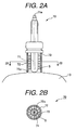
- Figures 2A and 2B contain enlarged cross-sectional views of the non-equilibrium plasma discharge device 70.
- the non-equilibrium plasma discharge device 70 of the illustrated embodiment discharges non-equilibrium plasma by using a barrier discharge. Therefore, in this embodiment, the non-equilibrium plasma discharge device 70 is a barrier discharge device.
- the non-equilibrium plasma discharge device 70 comprises a central electrode 71 and a tubular electrode 72.
- the central electrode 71 is a rod-shaped electrical conductor. The entire periphery of the central electrode 71 is covered by a dielectric material (insulating material) 73.
- the central electrode 71 is connected to the high-voltage high-frequency generator 80 via a terminal 71 a.
- An AC voltage is applied to the central electrode 71 upon being generated by the high-voltage high-frequency generator 80.
- the value, application duration, AC frequency, application timing, and other characteristics of the AC voltage are controlled (set) according to the operating state of the engine 1.
- the tubular electrode 72 is a tubular electrical conductor.
- the tubular electrode 72 is attached to the cylinder head.
- the inner periphery side of the tubular electrode 72 is a discharge chamber 72a.
- the central electrode 71 protrudes into the discharge chamber 72a.
- the central electrode 71 is provided on the top side of the substantial center of the combustion chamber.
- the center of the central electrode is substantially parallel to a line extending through the center of the combustion chamber.
- the distance from the central electrode 71 to the dielectric material and the distance from the dielectric material to the tubular electrode 72 are set to be substantially the same.
- streamers S are generated between the tubular electrode 72 and the dielectric material 73 as shown in Figure 2A .
- a plurality of streamers S is generated in the vertical direction as shown in Figure 2A .
- the streamers are branched into thin streaks, and Figure 2A shows a state in which six streamers are generated on both the right and left sides of the dielectric material 73.
- the streamers are also formed in a radial pattern about the dielectric material 73, as shown in Figure 2B.
- Figure 2B shows a state in which twelve streamers are formed in a radial pattern about the dielectric material 73.
- the non-equilibrium plasma discharge device 70 can generate a large amount of radicals in the discharge chamber 72a by forming a plurality of streamers S. It is also possible for multipoint simultaneous ignition, i.e., a volumetric ignition (hereinafter referred to as "volume ignition”), to occur within the discharge chamber.
- volume ignition a volumetric ignition
- the non-equilibrium plasma discharge device 70 can perform multiple electric discharges within a predetermined time, whereby a large amount of radicals can be generated in the discharge chamber 72a. This will be described with reference to Figures 3A and 3B.
- Figures 3A and 3B contain diagrams showing the electric discharges obtained when an AC voltage (electric potential) is applied.
- Figure 3A is a diagram showing the electric discharges obtained when an AC voltage (electric potential) is applied by a spark ignition discharge mechanism in accordance with a comparative example of a conventional discharge mechanism.
- Figure 3B is a diagram showing the electric discharges obtained when an AC voltage (electric potential) is applied by the electric discharge device in accordance with the illustrated embodiment.
- the dielectric material (insulating material) 73 covers the central electrode 71.
- the dielectric material 73 acts as a capacitor.
- a barrier discharge non-equilibrium plasma discharge
- an electric charge is accumulated on the surface of the dielectric material 73.
- the barrier discharge occurs between the dielectric material 73 and the tubular electrode 72 when the absolute value of the difference between the electric potential V0 created by the applied voltage and the electric potential Vw created by the surface electric charge of the dielectric material 73 reaches a discharge voltage Vd, as shown in Figure 3B .
- streamers S are formed at a plurality of locations in the discharge chamber 72a in the non-equilibrium plasma discharge device 70, and eight barrier discharges (non-equilibrium plasma discharges) occur within the discharge time t, as shown in Figure 3B .
- the non-equilibrium plasma discharge device 70 can increase the number of discharges in the same time (discharge time t) to a greater level than that obtained with a sparkplug in a conventional method.
- the number of discharges can also be increased by increasing the voltage value of the AC voltage applied to the non-equilibrium plasma discharge device 70 because increasing the voltage value increases the likelihood that the absolute value of the difference between the electric potential V 0 created by the applied voltage and the electric potential Vw created by the surface electric charge of the dielectric material 73 will reach the discharge voltage Vd.
- Figure 4 is a diagram showing various methods for increasing the discharge energy of the electric discharge device.
- the discharge energy of the non-equilibrium plasma discharge device 70 is controlled by the voltage value, application duration, and AC frequency of the AC voltage from the high-voltage high-frequency generator 80.
- One method of increasing the discharge energy of the non-equilibrium plasma discharge device 70 is to increase the voltage value of the AC voltage in the manner shown in plot (B-1) of Figure 4 relative to the waveform of a reference AC applied voltage (plot (A) of Figure 4 ).
- the discharge energy of the non-equilibrium plasma discharge device 70 can also be increased by increasing the applied duration as in plot (B-2) of Figure 4 , or increasing the AC frequency as in plot (B-3) of Figure 4 .
- Figures 5A-5C are simple link diagrams showing the arrangement of a multi-link variable compression ratio mechanism.
- the mechanical compression ratio can be varied by rotating the control shaft 25 and varying the position of the connecting pin 24.
- the connecting pin 24 is at position A as shown in Figure 5C
- the top dead center (TDC) is at a high level, resulting in a high compression ratio.
- the connecting pin 24 is at position B as shown in Figures 5B and 5C
- the control link 13 is pushed upward, and the position of the connecting pin 23 rises.
- the lower link 12 is thereby rotated counterclockwise around the crank pins 33b, the connecting pin 22 moves down, and the piston 32 in the piston top dead center (TDC) moves to a lower position. Therefore, the compression ratio is low.
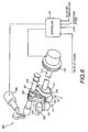
- FIG. 6 is a perspective view showing a variable valve timing mechanism for adjusting the opening and closing period of a valve.
- the engine 1 further comprises a variable valve timing mechanism 200.
- the mechanism disclosed, for example, in Japanese Laid-Open Patent Application No. 11-107725 can be used as the variable valve timing mechanism 200. This is described with reference to the drawings.
- the variable valve timing mechanism 200 comprises a camshaft 210, a link arm 220, a valve lift control shaft 230, a rocker arm 240, a link member 250, and oscillating cams 260.
- Cam followers 63 are pushed by the oscillation of the oscillating cams 260, thus opening and closing valves (intake valves) 61.
- the camshaft 210 is rotatably supported at the top part of the cylinder head along the longitudinal direction of the engine. One end of the camshaft 210 is inserted through a cam sprocket 270. The cam sprocket 270 is rotated by the transmission of torque from the crankshaft 33 of the engine. The camshaft 210 rotates together with the cam sprocket 270. The camshaft 210 can rotate relative to the cam sprocket 270 by hydraulic pressure, and the phase of the camshaft 210 relative to the cam sprocket 270 can be thereby varied. This type of structure makes it possible to vary the rotational phase of the camshaft 210 relative to the crankshaft 33. A cam 211 is fixed to the camshaft 210.
- the cam 211 rotates integrally with the camshaft 210.
- the pair of oscillating cams 260 connected by pipes is inserted through the camshaft 210.
- the oscillating cams 260 oscillate about the camshaft 210 as a rotational center, causing the cam followers 63 to perform a stroke.
- the link arm 220 is supported by the insertion of the cam 211.
- the valve lift control shaft 230 is disposed parallel to the camshaft 210.
- a cam 231 is formed integrally on the valve lift control shaft 230.
- the valve lift control shaft 230 is controlled by an actuator 280 so as to rotate within a predetermined range of rotational angles.
- the rocker arm 240 is supported by the insertion of the cam 231 and is connected to the link arm 220.
- the link member 250 is connected to the rocker arm 240.
- the camshaft 210 is inserted through the oscillating cams 260, which can oscillate about the camshaft 210.
- the oscillating cams 260 are connected to the link member 250.
- the oscillating cams 260 move up and down, pushing down on the cam followers 63 and opening and closing the valves 61.
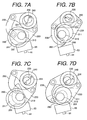
- variable valve timing mechanism 200 Next, the action of the variable valve timing mechanism 200 will be described with reference to Figures 7A-7D .
- Figures 7A and 7B are views showing the manner in which the stroke amount of the cam followers 63 is maximized to maximize the lift amount of the valves 61.
- Figure 7A shows the manner in which cam noses 262 are at their highest positions, and the oscillation direction of the oscillating cams 260 is inverted. At this time, the cam followers 63 are at their highest stroke positions, and the valves 61 are in a closed state.
- Figure 7B shows the manner in which the cam noses 262 are at their lowest positions, and the oscillation direction of the oscillating cams 260 is inverted. At this time, the cam followers 63 are at bottom end positions of their strokes, and the valves 61 are in a state of maximum lift.
- Figures 7C and 7D are views showing the manner in which the stroke amount of the cam followers 63 is minimized.
- Figure 7C shows the manner in which the cam noses 262 are at their highest stroke positions and the oscillating direction of the oscillating cams 260 is inverted.
- Figure 7D shows the manner in which the cam noses 262 are at their lowest positions and the oscillation direction of the oscillating cams 260 is inverted.
- the stroke amount of the cam followers 63 is zero
- the lift amount of the valves 61 is also zero. Therefore, in Figures 7C and 7D , the valves 61 are always in a closed state regardless of the action of the oscillating cams 260.
- valve lift control shaft 230 is rotated to lower the position of the cam 231 and to set the axial center P1 below the axial center P2, as shown in Figures 7A and 7B .
- the entire rocker arm 240 is thereby moved downward.
- valve lift control shaft 230 is rotated to raise the position of the cam 231, and the axial center P1 is set above and to the right of the axial center P2, as shown in Figures 7C and 7D .
- the entire rocker arm 240 is thereby moved upward.
- Figure 8 is a graph showing the valve lift amount and the opening and closing periods in the variable valve timing mechanism 200.
- the solid-lines curves indicate the lift amount and the opening and closing timings of the valves 61 when the valve lift control shaft 230 is rotated.
- the broken-line curves indicate the opening and closing periods of the valves 61 when the phase of the camshaft 210 is varied relative to the cam sprocket 270.
- the lift amount and operating angle of the valves 61 can be continually varied.
- the lift amount and operating angle of the valves 61 can be continually and freely varied by varying the angle of the valve lift control shaft 230 and the phase of the camshaft 210 relative to the cam sprocket 270.
- FIGS 9A-9E are graphs showing an example of an operation map of the engine having a non-equilibrium plasma discharge function.
- the range of extremely low load for example, the engine is in an idle state
- the air-fuel ratio A/F is set to a constant value ( Figure 9A ).
- the discharge start timing is set to a constant timing during the intake stroke ( Figure 9B ).
- the constant timing is set near the most advanced angle within the low load range described hereinafter.
- the start timing occurs after the intake valve has opened.
- the end timing of the discharge is set to occur before the intake valve closes. The reasons for these settings will be explained below.
- the discharge energy is set to a level that increases the lower the load is ( Figure 9C ).
- the intake valve close timing (IVC) is set to be more advanced than the bottom dead center (BDC), and the operation proceeds according to the Miller cycle. This timing IVC is set to be more advanced the lower the load is ( Figure 9D ).
- the mechanical compression ratio is set to a high level ( Figure 9E ).
- the air-fuel ratio A/F is set to decrease (i.e., become richer) as the load increases ( Figure 9A ).
- the discharge start timing is set to occur during the intake stroke when the load is low, retard as the load increases, and occur during the compression stroke when the load is high ( Figure 9B ). The reasons for these settings are described hereinafter.
- the discharge energy is set to a constant value ( Figure 9C ).
- the intake valve close timing (IVC) is set to a constant value more retarded than the bottom dead center (BDC) ( Figure 9D ).
- the mechanical compression ratio is set to a high level ( Figure 9E ).
- the air-fuel ratio A/F is set to decrease (i.e., become richer) as the load increases ( Figure 9A ).
- the discharge start timing is set to be much more retarded than in the low load range, and is also set to become more retarded as the load increases ( Figure 9B ).
- the discharge energy is set to a constant value ( Figure 9C ).
- the intake valve close timing (IVC) is set to a constant value that is more retarded than the bottom dead center (BDC) ( Figure 9D ).
- the mechanical compression ratio is set to be much less than in the extremely low load range or the low load range, and is also set to decrease as the load increases ( Figure 9E ).
- the air-fuel ratio A/F is set to decrease (i.e., become richer) as the load increases ( Figure 9A ).
- the discharge start timing is set to become more retarded as the load increases ( Figure 9B ).
- the discharge energy is set to a constant value ( Figure 9C ).
- the intake valve close timing (IVC) is set to a constant value that is more retarded than the bottom dead center (BDC) ( Figure 9D ).
- the mechanical compression ratio is set to be even less than in the low-to-moderate load range, and is also set to decrease as the load increases ( Figure 9E ).
- the discharge start timing is set to occur during the intake stroke when the load is low.
- the discharge start timing is set to occur after the intake valve has opened and the exhaust valve has closed.
- the start timing occurs after the exhaust valve has closed.
- the start timing occurs after the intake valve has opened.
- the end timing of the discharge occurs before the intake valve closes.
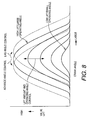
- Figure 10 is a graph showing the variation in the heat generation rate depending on if and when the non-equilibrium plasma discharge occurs.
- Curve A in the diagram is shown as a comparative example, and is a curve indicating variation in the heat generation rate when a non-equilibrium plasma discharge is not performed (i.e., radicals are not generated). It can be seen from curve A that the peak of the heat generation rate occurs at a crank angle ⁇ a .
- the heat generation rate is substantially symmetrical before and after this peak, and a crank angle MB ⁇ 50% (discussed below) at which the mass combustion ratio is 50% substantially coincides with ⁇ a .
- Curve B in the diagram is a curve indicating variation in the heat generation rate when a non-equilibrium plasma discharge is initiated during the compression stroke (for example, 135 deg BTDC). It can be seen from curve B that the peak of the heat generation rate occurs at a crank angle ⁇ b at a more advanced level than the peak obtained when the non-equilibrium plasma discharge is not performed (curve A), and the heat generation rate rises more rapidly than when the non-equilibrium plasma discharge is not performed (curve A).
- the heat generation rate is substantially symmetrical before and after this peak, and the crank angle MB ⁇ 50%, at which the mass combustion ratio is 50%, substantially coincides with ⁇ b .
- Curve C in the diagram is a curve indicating variation in the heat generation rate when a non-equilibrium plasma discharge is initiated during the intake stroke (for example, 270 deg BTCD). It can be seen from curve C that the peak of the heat generation rate occurs at a crank angle ⁇ c even more advanced than the peak obtained when the non-equilibrium plasma discharge is initiated during the compression stroke (curve B), and the variation in the heat generation rate is steep.
- the heat generation rate is substantially symmetrical before and after this peak, and the crank angle MB ⁇ 50%, at which the mass combustion ratio is 50%, substantially coincides with ⁇ c .
- Figures 11A-C contain drawings schematically depicting the state in which radicals are distributed within the cylinder and serve to illustrate the result of analyzing the reasons that bring about the curves shown in Figure 10 .
- the radicals are schematically depicted by the dots in the drawings. Research has shown that differences in the variation in the heat generation rate brought about by the discharge start timing (as shown in Figure 10 ) are caused by the state in which radicals are distributed within the cylinder.
- the radicals are in a state of molecular dissociation induced by collisions of high-energy electrons with fuel or air molecules. Such radicals have the characteristic of readily inducing oxidation reactions (i.e., combustion) and creating chain oxidation reactions.
- the radicals undergo combustion substantially all at once throughout the entire cylinder 31 a when the pressure in the cylinder increases while radicals having such characteristics are dispersed throughout the entire cylinder 31a. Research has shown that the heat generation rate also rises suddenly because a combustion reaction takes place in this manner throughout the entire cylinder 31 a.
- Initiating a non-equilibrium plasma discharge during the compression stroke brings about an intermediate state in the cylinder 31 a immediately before ignition, that is, a state between the case of no non-equilibrium plasma discharge ( Figure 11A ) and the case in which a non-equilibrium plasma discharge is initiated during the intake stroke ( Figure 11 C) .
- the intermediate state fewer radicals are distributed in the vicinity of the non-equilibrium plasma discharge device 70 ( Figure 11 B) . This is because there is a short period from the time when the non-equilibrium plasma discharge device 70 performs a non-equilibrium plasma discharge to generate radicals until the time of ignition, and the radicals are therefore unable to widely disperse.
- curve B is an intermediate curve between curve A and curve C.
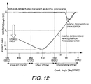
- Figure 12 is a graph showing the relationship between the discharge start timing and the crank angle at which the mass combustion ratio is 50%.
- crank angle MB ⁇ 50% at which the mass combustion ratio is 50% As described above, varying the non-equilibrium plasma discharge start timing causes a change in the crank angle MB ⁇ 50% at which the mass combustion ratio is 50%. In other words, the auto-ignition properties change. This relationship is plotted in Figure 12 . Up until the discharge start timing reaches approximately 270 deg BTDC, the crank angle MB ⁇ 50% at which the mass combustion ratio is 50% advances as the discharge start timing is advanced. In other words, auto-ignition properties are improved. When the discharge start timing is advanced to 270 deg BTDC or greater, the crank angle MB ⁇ 50% at which the mass combustion ratio is 50% becomes more retarded as the discharge start timing is advanced.
- crank angle MB ⁇ 50% at which the mass combustion ratio is 50% advances the farthest (i.e., auto-ignition properties are best) when the discharge start timing is approximately 270 deg BTDC.
- the intake valve and exhaust valve of the engine are normally opened and closed. It is believed that initiating a non-equilibrium plasma discharge after the exhaust valve has closed causes the air-fuel mixture drawn in through the intake valve to scatter more readily and auto-ignition properties to improve in comparison with a case in which a non-equilibrium plasma discharge is initiated during the period in which the exhaust valve has not yet closed.
- the non-equilibrium plasma discharge device 70 continuously performs a non-equilibrium plasma discharge for a predetermined time (predetermined crank angle period) following discharge initiation.
- the air flow rate decreases after the intake valve is closed.
- the radicals do not disperse as readily as when the air flow rate is high. Therefore, to efficiently disperse radicals within the cylinder, the end period of the non-equilibrium plasma discharge is before the closing of the intake valve.
- the heat generation timing (the crank angle MB ⁇ 50% at which the mass combustion ratio is 50%) can be controlled by adjusting the discharge start timing.
- the auto-ignition properties of the air-fuel mixture can be controlled by adjusting the discharge start timing.
- the discharge start timing is adjusted according to the air-fuel ratio (load).
- Figure 12 also shows a case in which radicals are generated by a sparkplug. It is clear from the diagram that even if radicals are generated by a sparkplug, there is little difference from cases in which radicals are not generated.
- the engine control apparatus is provided such that a non-equilibrium plasma discharge is initiated during the intake stroke so that radicals are widely distributed within the cylinder when the air-fuel ratio corresponds to an extremely diluted (lean) condition.
- the auto-ignition properties are adjusted to retard the discharge start timing as the load increases (as the amount of fuel increases and the air-fuel ratio corresponds to a richer mixture).
- the above factors are the reasons that the discharge start timing is set to occur during the intake stroke when the load is low, to become more retarded as the load increases, and to occur during the compression stroke when the load is high ( Figure 9B ).
- the mechanical compression ratio is set to a high level when the engine is operating in the low load region or the extremely low load region ( Figure 9E ). The reasons for these settings will now be described.
- An engine having a multi-link variable compression ratio mechanism has the characteristic of having a longer period in which the piston stays in proximity to the top dead center in comparison with a common engine in which the compression ratio is constant (hereinafter referred to as a "normal engine"). Due to this characteristic, an engine having a multi-link variable compression ratio mechanism, even at a high compression ratio, is less susceptible to knocking than a common engine is, comparatively high combustion energy can be obtained even with ultra-lean combustion, and stable combustion can be maintained.
- Figure 13 is a graph showing the piston behavior in a multi-link variable compression ratio mechanism, wherein the upper portion of Figure 13 is an enlarged view of the dotted line portion of the lower portion of the figure.
- the thin solid-line curves indicate the piston behavior in a multi-link variable compression ratio mechanism engine having the same compression ratio as a normal engine.
- the multi-link variable compression ratio mechanism engine has a longer period in which the piston is in proximity to the top dead center than does a normal engine having the same compression ratio.
- the period L 1 in which the piston is in proximity to the top dead center at a high compression ratio is longer than the period L 2 in which the piston is in proximity to the top dead center at a low compression ratio.
- the inequality L 1 > L 2 is true in Figure 13 .
- the multi-link variable compression ratio mechanism engine has a longer period in which the piston is in proximity to the top dead center than does a normal engine. Furthermore, the period in which the piston is in proximity to the top dead center is longer when the compression ratio is high.
- the fact that the piston is in proximity to the top dead center for a long time means that a high compression state is maintained for a long time during combustion. When a high compression state is maintained for a long time, knocking does not readily occur, and combustion is stable because comparatively high combustion energy can be obtained even during ultra-lean combustion.
- the multi-link variable compression ratio mechanism engine has the characteristics shown in Figure 14.
- Figure 14 is a graph showing the relationship between the air-fuel ratio and combustion stability.
- the thin line in the diagram denotes a normal engine, and the thick line denotes a multi-link variable compression ratio mechanism engine.
- the combustion stability limit is not compromised because the piston remains in proximity to the top dead center for a long time.
- Increasing the compression ratio e.g., to about 18
- A/F air-fuel ratio
- the above are the reasons the mechanical compression ratio is set to a high level in a load range at or below a low load ( Figure 9E ).
- the map load range in Figure 9 was set based on this knowledge.
- the intake valve close timing (IVC) is set to be more advanced than the bottom dead center (BDC), and the valve operation proceeds according to the Miller cycle.
- the timing is more advanced at lower loads ( Figure 9D ).
- the filling efficiency of intake air is thereby reduced, the effective compression ratio is lowered, and pump loss is reduced.
- the combustion amount decreases with decreased load (the air-fuel ratio is substantially constant because the air intake amount also decreases), the air-fuel mixture loses auto-ignition properties.
- the discharge energy is greatly increased at lower loads ( Figure 9C ).
- the map of the extremely low load range in Figure 9 was set based on the above knowledge. As shown, operation is possible even at extremely low load ranges.
- the compression ratio is reduced so that the air-fuel mixture does not undergo compression ignition. It is designed so that volumetric ignition is performed by the non-equilibrium plasma discharge device 70 during the compression stroke. The fuel in the vicinity of the non-equilibrium plasma discharge device 70 thereby undergoes flame propagation. The remaining unburned air-fuel mixture is adiabatically compressed by the burned air-fuel mixture and is made to undergo auto-ignition. As a result, knocking does not occur because the heat generation rate varies as shown by curve B in Figure 15 and does not suddenly increase to an excessive degree.
- the map of the low-to-moderate load range in Figure 9 is set based on the above. Operation is thereby made possible even in a low-to-moderate load range.
- Spark ignition is performed by the non-equilibrium plasma discharge device 70 at a moderate-to-high load or greater, whereby operation is possible even in a moderate-to-high load range.
- Figures 16A and 16B are graphs showing various effects of the present embodiment.
- the present embodiment it is possible to greatly expand the lean combustion limit because the discharge start timing is appropriately controlled according to the operating state as described above.
- Curve B depicts cases in which radicals are generated by a sparkplug, and combustion occurs by compression ignition.
- the lean combustion limit is an air-fuel ratio of AFb, and is somewhat leaner than the air-fuel ratio AFa of the lean combustion limit in normal cases.
- Curve C depicts cases in which radicals are generated by the non-equilibrium plasma discharge device 70, and combustion occurs by compression ignition.
- the lean combustion limit is an air-fuel ratio of AFc.
- the lean combustion limit can be greatly expanded in comparison with the air-fuel ratio AFa of the lean combustion limit in normal cases and in comparison with the air-fuel ratio AFb of the lean combustion limit in generation of radicals by a sparkplug and combustion by compression ignition.
- the operation shown by the broken-line curves can be arbitrarily selected because it is possible to control the crank angle MB ⁇ 50% at which the mass combustion ratio is 50% by adjusting the discharge start timing.
- the fuel consumption rate ISFC can be reduced as shown in Figure 16B .
- the present embodiment makes it possible to reduce the fuel consumption rate and to improve fuel consumption, regardless of the load.
- the central electrode and the dielectric material for covering the central electrode allow a non-equilibrium plasma discharge to generate radicals within a cylinder. Therefore, the auto-ignition properties of an air-fuel mixture during the compression stroke can be improved, the fuel consumption rate can consequently be reduced and fuel consumption can be improved, regardless of the load.
- FIG 17 is a simplified schematic cross-sectional view showing the operational configuration of the engine control apparatus having an electric discharge device in accordance with a second embodiment.
- the engine 1 having a non-equilibrium plasma discharge function of the first embodiment was a so-called port-injection engine in which the fuel injection valve 65 was provided to the intake port, but the electric discharge device can also be applied to a direct fuel-injection engine such as the one shown in Figure 17 , in which fuel is directly injected into the cylinder.
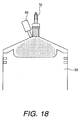
- the air-fuel mixture is stratified only in the vicinity of the non-equilibrium plasma discharge device 70 as shown in Figure 18 to make operation possible even with a lean air-fuel ratio.
- Generating radicals in this type of lean air-fuel mixture allows the lean combustion limit to be expanded, the fuel consumption rate to be reduced, and fuel consumption to be improved.
- FIG. 19A-19E An example of an operation map for the engine having such a barrier discharge function is shown in Figures 19A-19E .
- An interval in which a non-equilibrium plasma discharge is not performed is provided in the vicinity of a comparatively high load within the low load range ( Figures 19A and 19B ).
- a high compression ratio is set by the variable compression ratio mechanism, and knocking does not readily occur. Therefore, there is an operation range in which lean combustion is possible even though a non-equilibrium plasma discharge is not performed.
- a non-equilibrium plasma discharge is performed in such an operating range, there is a danger that auto-ignition properties will improve excessively and that knocking will occur. In view of this, a non-equilibrium plasma discharge is not performed in the vicinity of comparatively high loads within the low load range.
- a stratified operation is performed ( Figure 19D ) and the air-fuel ratio A/F is made leaner (sparser) according to the load ( Figure 19A ).
- a non-equilibrium plasma discharge is performed because the auto-ignition properties must be improved along with the increase in sparseness of the air-fuel mixture.
- the discharge start timing is set to occur during the intake stroke, wherein the effects of auto-ignition properties improvement are high ( Figure 19B ).
- the auto-ignition properties are improved by increasing the discharge energy along with the increase in sparseness ( Figure 19C ).
- the invention can be carried out even with a direct fuel-injection engine, the fuel consumption rate can be reduced and fuel consumption can be improved, regardless of the load.
- FIG. 20 an engine control apparatus in accordance with a third embodiment will now be explained.
- the engine control apparatus of the first embodiment is replaced in Figure 1 with a modified structure as discussed below.
- the parts of the third embodiment that are identical to the parts of the first embodiment will be given the same reference numerals as the parts of the first embodiment.
- the descriptions of the parts of the third embodiment that are identical to the parts of the first embodiment can be omitted for the sake of brevity.
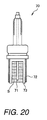
- FIG 20 is a simplified schematic cross-sectional view showing the third embodiment of the engine control apparatus having an electric discharge device.
- a dielectric layer (insulating layer) 73 is formed on the inner periphery of the tubular electrode 72, and the central electrode 71 is exposed.
- the distal end of the dielectric layer (insulating layer) 73 protrudes farther toward the combustion chamber than does the distal end of the tubular electrode 72 or the distal end of the central electrode 71.
- the dielectric layer 73 acts as a capacitor in the configuration of the present embodiment, and the same effects as in the first embodiment are obtained.
- FIG. 21A and 21B an engine control apparatus in accordance with a fourth embodiment will now be explained.
- the engine control apparatus of the first embodiment is replaced in Figure 1 with a modified structure as discussed below.
- the parts of the fourth embodiment that are identical to the parts of the first embodiment will be given the same reference numerals as the parts of the first embodiment.
- the descriptions of the parts of the fourth embodiment that are identical to the parts of the first embodiment can be omitted for the sake of brevity.
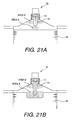
- Figures 21A and 21B contain simplified schematic cross-sectional views showing the fourth embodiment of the engine control apparatus having an electric discharge device.
- the central electrode 71 protrudes into the combustion chamber.
- the non-equilibrium plasma discharge device 70 performs a non-equilibrium plasma discharge within the combustion chamber as shown in Figure 21A .
- the top surface of the piston 32 or the inside wall surface of the cylinder head functions as an electrode.
- a non-equilibrium plasma discharge is performed and radicals are generated in the area A between the top surface of the piston 32 and the dielectric layer (insulating layer) 73 of the central electrode 71, or in the area B between the inside wall surface of the cylinder head and the dielectric layer (insulating layer) 73.
- Whether the non-equilibrium plasma discharge is performed in area A or B is determined by the position of the piston 32 when an AC voltage is applied to the non-equilibrium plasma discharge device 70.
- the discharge area of non-equilibrium plasma discharge can be selected by controlling the application timing of the AC voltage applied to the non-equilibrium plasma discharge device 70.
- a concave part can be formed in the top surface of the piston 32 as shown in Figure 21B , and the configuration can be designed so that non-equilibrium plasma discharge is performed between the concave part and the distal end of the dielectric material (insulating material) 73 of the central electrode 71.
- FIG. 22A and 22B an engine control apparatus in accordance with a fifth embodiment will now be explained.
- the engine control apparatus of the first embodiment is replaced in Figure 1 with a modified structure as discussed below.
- the parts of the fifth embodiment that are identical to the parts of the first embodiment will be given the same reference numerals as the parts of the first embodiment.
- the descriptions of the parts of the fifth embodiment that are identical to the parts of the first embodiment can be omitted for the sake of brevity.
- FIGS 22A and 22B contain simplified schematic cross-sectional views showing the fifth embodiment of the engine control apparatus having an electric discharge device.
- the dielectric material (insulating material) 73 is shorter in comparison with the fourth embodiment, and the central electrode 71 is exposed within the combustion chamber.
- a dielectric layer (insulating layer) 32a is also formed on the top surface of the piston 32.
- the non-equilibrium plasma discharge device 70 performs a non-equilibrium plasma discharge within the combustion chamber as shown in Figure 22A . Specifically, a non-equilibrium plasma discharge is performed and radicals are generated in the area A between the distal end of the central electrode 71 and the dielectric layer (insulating layer) 32a on the top surface of the piston 32.
- a concave part is formed in the top surface of the piston 32, and the dielectric layer (insulating layer) 32a is formed in the inner periphery of the concave part as shown in Figure 22B , a non-equilibrium plasma discharge is performed between the dielectric layer (insulating layer) 32a and the distal end of the central electrode 71.
- FIG. 23 an engine control apparatus in accordance with a sixth embodiment will now be explained.
- engine control apparatus of the first embodiment is replaced in Figure 1 with a modified structure as discussed below.
- the parts of the fifth embodiment that are identical to the parts of the first embodiment will be given the same reference numerals as the parts of the first embodiment.
- the descriptions of the parts of the sixth embodiment that are identical to the parts of the first embodiment can be omitted for the sake of brevity.
- FIG 23 is a simplified schematic cross-sectional view of a portion of a multi-link engine that contains an electric discharge device in accordance with a sixth embodiment.
- the non-equilibrium plasma discharge device 70 is connected to a high-voltage short-pulse generator 81, instead of the high-voltage high-frequency generator 80 of the first-fifth embodiments.
- the non-equilibrium plasma discharge device 70 is different than in the previously described embodiments regarding some details. These differences will now be explained with reference to Figures 24A and 24B .
- the high-voltage short-pulse generator 81 constitutes a voltage application device.
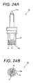
- Figures 24A and 24B contain enlarged views of the non-equilibrium plasma discharge device 70.
- Figure 24A is a partial cross-sectional view of the electric discharge device of the engine shown in Figure 23 .
- Figure 24B is a cross-sectional view of the electric discharge device illustrated in Figure 24A , taken along section line 24B-24B of Figure 24A .
- a short pulse voltage is applied across the electrodes of the non-equilibrium plasma discharge device 70 and the voltage is shut off before an arc discharge occurs, thereby producing radicals between the electrodes.
- the central electrode 71 is connected to the high-voltage short-pulse generator 81 via the terminal 71 a.
- a voltage value, pulse width, pulse count, and application duration of the voltage applied to the central electrode 71 by the high-voltage short-pulse generator 81 is controlled in accordance with the operating state of the engine.
- streamers S develop between the central electrode 71 and the tubular electrode 72 as shown in Figure 24A .
- a plurality of streamers S is generated in the vertical direction as shown in Figure 24A.
- Figure 24A illustrates a state in which four streamers have occurred on each of the right and left sides of the central electrode 71.
- the streamers extend in a radial fashion from the central electrode 71.
- Figure 24B illustrates a state in which twelve streamers are generated in a radial fashion around the central electrode 71.
- the non-equilibrium plasma discharge device 70 can generate a large amount of radicals in the discharge chamber 72a by forming a plurality of streamers S. It is also possible for multipoint simultaneous ignition, i.e., a volumetric ignition (hereinafter referred to as "volume ignition”), to occur within the discharge chamber.
- volume ignition a volumetric ignition
- Figure 25 is a graph showing the relationship between an applied voltage and an applied voltage pulse width of the electric discharge device.
- the pulse width of the applied voltage is indicated on the horizontal axis, and the applied voltage is indicated on the vertical axis.
- the non-equilibrium plasma discharge device 70 in order for the non-equilibrium plasma discharge device 70 to execute a non-equilibrium plasma discharge and form a plurality of streamers S, it is necessary to a apply a high voltage with a short pulse width (e.g., several tens to several hundreds of nanoseconds), i.e., a voltage lying within the region P, to the non-equilibrium plasma discharge device 70.
- a short pulse width e.g., several tens to several hundreds of nanoseconds
- the location of the boundary line A between non-equilibrium plasma discharge and thermal plasma discharge and the location of the lower limit voltage V 0 both change depending on a relative density of the gases inside the combustion chamber.
- the same effects as the first embodiment can be obtained when a short pulse voltage is applied to the non-equilibrium plasma discharge device.
- a short pulse voltage is applied to the non-equilibrium plasma discharge device.
- the waveform of the alternating current is not limited to a sine curve ( Figure 26A ).
- a bipolar multiple pulse power source may also be used, such as is shown in Figure 26B .
- variable compression ratio mechanism a multi-link mechanism was described as the variable compression ratio mechanism, but other possible examples include, e.g., a mechanism in which a hydraulic device is incorporated into the piston as such to adjust the height of the top surface of the piston, a mechanism in which the distance between the cylinder head and the cylinder block can be adjusted, and a mechanism in which the piston height can be adjusted by offsetting the center of the crankshaft.
- the mechanism for adjusting the valve timing of the intake valve can also be, e.g., an oscillating cam which uses a link (Japanese Laid-Open Patent Application No. 2000-213314 ), a mechanism in which the cam is twisted in the manner of a vane-type variable valve timing system (Japanese Laid-Open Patent Application No. 9-60508 ), a system in which a switch is made between two types of cams having different timings in the manner of a direct variable valve timing system (Japanese Laid-Open Patent Application No. 4-17706 ), or the like.
- an oscillating cam which uses a link Japanese Laid-Open Patent Application No. 2000-213314
- a mechanism in which the cam is twisted in the manner of a vane-type variable valve timing system Japanese Laid-Open Patent Application No. 9-60508
- a system in which a switch is made between two types of cams having different timings in the manner of a direct variable valve timing system Japanese Laid-
- the term “comprising” and its derivatives, as used herein, are intended to be open ended terms that specify the presence of the stated features, elements, components, groups, integers, and/or steps, but do not exclude the presence of other unstated features, elements, components, groups, integers and/or steps.
- the foregoing also applies to words having similar meanings such as the terms, “including”, “having” and their derivatives.
- the terms “part,” “section,” “portion,” “member” or “element” when used in the singular can have the dual meaning of a single part or a plurality of parts.
- the terms of degree such as “substantially”, “about” and “approximately” as used herein mean a reasonable amount of deviation of the modified term such that the end result is not significantly changed.
Landscapes
- Engineering & Computer Science (AREA)
- Chemical & Material Sciences (AREA)
- Combustion & Propulsion (AREA)
- Mechanical Engineering (AREA)
- General Engineering & Computer Science (AREA)
- Physics & Mathematics (AREA)
- Optics & Photonics (AREA)
- Ignition Installations For Internal Combustion Engines (AREA)
- Output Control And Ontrol Of Special Type Engine (AREA)
- Electrical Control Of Air Or Fuel Supplied To Internal-Combustion Engine (AREA)
Abstract
Description
- The present invention generally relates to an engine control apparatus and method and particularly, but not exclusively, to an apparatus and method for controlling an internal combustion engine comprising an electric discharge device. Aspects of the invention relate to an apparatus, to a structure, to an engine, to a method and to a vehicle
- An electric discharge device has been proposed for an internal combustion engine in which the air-fuel mixture is ignited in an assisted manner by a sparkplug. In this electric discharge device radicals are generated in a cylinder and the auto-ignition properties of the air-fuel mixture are improved (see, Japanese Laid-Open Patent Application No.
2001-20842 - As mentioned above, it has been discovered that, in order to improve the auto-ignition properties of the air-fuel mixture, a sparkplug can be used to generate radicals in the cylinder. However, since spark ignition is a thermal plasma discharge, the efficiency of radical generation is low even if spark ignition is induced by a sparkplug as in the conventional apparatus previously described. Moreover, in this conventional apparatus the amount of radicals generated is limited. It is therefore believed that the effects of improving the auto-ignition properties are small.
- It is an aim of the present invention to address this issue and to improve upon known technology. Embodiments of the invention may provide a control apparatus and a control method for an internal combustion engine that enables the auto-ignition properties of the air-fuel mixture to be improved in comparison with conventional internal combustion engines. Other aims and advantages of the invention will become apparent from the following description, claims and drawings.
- Aspects of the invention therefore provide an apparatus, a structure, an engine, a method and a vehicle as claimed in the appended claims.
- According to another aspect of the invention for which protection is sought, there is provided an engine control apparatus comprising an electric discharge device including a first electrode and a second electrode arranged opposite the first electrode to produce radicals within a combustion chamber of an internal combustion engine by a non-equilibrium plasma discharge that is generated between the electrodes before auto-ignition of the air-fuel mixture occurs, a voltage application device operatively coupled to the first electrode for applying a voltage between the first and second electrodes to generate the non-equilibrium plasma between the first and second electrodes, a fuel supplying device arranged to form an air-fuel mixture inside the combustion chamber and a control unit operatively couple to the electric discharge device to set a discharge start timing of the electric discharge device to occur during an intake stroke of the internal combustion engine.
- In an embodiment, the control unit sets the discharge start timing of the electric discharge device to occur after an intake valve opens in the internal combustion engine.
- In an embodiment, the control unit sets the discharge start timing of the electric discharge device to occur after an exhaust valve opens in the internal combustion engine.
- In an embodiment, the control unit sets the discharge start timing of the electric discharge device to occur before an intake valve closes in the internal combustion engine.
- In an embodiment, the control unit sets the discharge start timing of the electric discharge device to occur before an intake valve closes in the internal combustion engine.
- In an embodiment, the control unit sets the discharge start timing of the electric discharge device to occur before an intake valve closes in the internal combustion engine.
- In an embodiment, the electric discharge device is a short pulse application discharge device that applies a short pulse voltage across the first electrode and the second electrode such that the voltage stops before an arc discharge occurs, and the radicals improve an auto-ignition property of the air-fuel mixture during a compression stroke due to the non-equilibrium plasma discharge generated between the electrodes.
- In an embodiment, the electric discharge device is a short pulse application discharge device that applies a short pulse voltage across the first electrode and the second electrode such that the voltage stops before an arc discharge occurs, and the radicals improve an auto-ignition property of the air-fuel mixture during a compression stroke due to the non-equilibrium plasma discharge generated between the electrodes.
- In an embodiment, the electric discharge device is a short pulse application discharge device that applies a short pulse voltage across the first electrode and the second electrode such that the voltage stops before an arc discharge occurs, and the radicals improve an auto-ignition property of the air-fuel mixture during a compression stroke due to the non-equilibrium plasma discharge generated between the electrodes.
- In an embodiment, the electric discharge device is a barrier discharge device in which a dielectric material is formed on one of the first and second electrodes such that when a voltage is applied across the first and second electrodes the radicals improve an auto-ignition property of an air-fuel mixture during a compression stroke due to a barrier discharge generated between the one of the first and second electrodes with dielectric material and the other of the first and second electrodes.
- In an embodiment, the electric discharge device is a barrier discharge device in which a dielectric material is formed on one of the first and second electrodes such that when a voltage is applied across the first and second electrodes the radicals improve an auto-ignition property of an air-fuel mixture during a compression stroke due to a barrier discharge generated between the one of the first and second electrodes with dielectric material and the other of the first and second electrodes.
- In an embodiment, the electric discharge device is a barrier discharge device in which a dielectric material is formed on one of the first and second electrodes such that when a voltage is applied across the first and second electrodes the radicals improve an auto-ignition property of an air-fuel mixture during a compression stroke due to a barrier discharge generated between the one of the first and second electrodes with dielectric material and the other of the first and second electrodes.
- According to a further aspect of the invention for which protection is sought, there is provided an engine control apparatus comprising electric discharge means for producing radicals within a combustion chamber of an internal combustion engine by a non-equilibrium plasma discharge that is generated before auto-ignition of the air-fuel mixture occurs, means for applying voltage to electric discharge means to generate the non-equilibrium plasma between the first and second electrodes, means for forming an air-fuel mixture inside the combustion chamber and means for setting a discharge start timing of the electric discharge means to occur during an intake stroke of the internal combustion engine.
- According to a still further aspect of the invention for which protection is sought, there is provided an engine control method comprising applying a voltage between first and second electrodes of an electric discharge device to produce radicals within a combustion chamber of an internal combustion engine by a non-equilibrium plasma discharge that is generated between the first and second electrodes before auto-ignition of the air-fuel mixture occurs, forming an air-fuel mixture inside the combustion chamber and controlling the electric discharge device to set a discharge start timing of the electric discharge device to occur during an intake stroke of the internal combustion engine.
- In an embodiment, the controlling of the electric discharge device further includes setting the discharge start timing of the electric discharge device to occur after an intake valve opens in the internal combustion engine.
- In an embodiment, the controlling of the electric discharge device further includes setting the discharge start timing of the electric discharge device to occur after an exhaust valve opens in the internal combustion engine.
- In an embodiment, the controlling of the electric discharge device further includes setting the discharge start timing of the electric discharge device to occur before an intake valve closes in the internal combustion engine.
- For example, an engine control apparatus according to an embodiment may comprise an electric discharge device, a voltage application device, a fuel supplying device, and a control unit. The electric discharge device includes a first electrode and a second electrode. The second electrode is arranged opposite the first electrode to produce radicals within a combustion chamber of an internal combustion engine by a non-equilibrium plasma discharge that is generated between the electrodes before auto-ignition of the air-fuel mixture occurs. The voltage application device is operatively coupled to the first electrode for applying a voltage between the first and second electrodes to generate the non-equilibrium plasma between the first and second electrodes. The fuel supplying device forms an air-fuel mixture inside the combustion chamber. The control unit is operatively coupled to the electric discharge device to set a discharge start timing of the electric discharge device to occur during an intake stroke of the internal combustion engine.
- Within the scope of this application it is envisaged that the various aspects, embodiments, examples, features and alternatives set out in the preceding paragraphs, in the claims and/or in the following description and drawings may be taken individually or in any combination thereof.
- The present invention will now be described, by way of example only, with reference to the accompanying drawings, in which:
-
Figure 1 is a simplified schematic cross-sectional view of a portion of a multi-link engine that contains an electric discharge device in accordance with a first embodiment; -
Figure 2A is a partial cross-sectional view of the electric discharge device of the engine shown inFigure 1 ; -
Figure 2B is a cross-sectional view of the electric discharge device illustrated inFigure 2A , taken alongsection line 2B-2B ofFigure 2A ; -
Figure 3A is a diagram showing the electric discharges obtained when an AC voltage (electric potential) is applied to a spark ignition discharge mechanism in accordance with a comparative example of a conventional discharge mechanism; -
Figure 3B is a diagram showing the electric discharges obtained when an AC voltage (electric potential) is applied to the electric discharge device in accordance with the first illustrated embodiment; -
Figure 4 is a diagram showing various methods for increasing the discharge energy of the electric discharge device; -
Figure 5A is a simple link diagram showing the arrangement of a multi-link variable compression ratio mechanism at a high compression ratio; -
Figure 5B is a simple link diagram showing the arrangement of the multi-link variable compression ratio mechanism at a low compression ratio; -
Figure 5C is a simple link diagram showing the method for varying the compression ratio using the multi-link variable compression ratio mechanism; -
Figure 6 is a perspective view of a variable valve timing mechanism for adjusting the opening and closing timing of a valve; -
Figure 7A is a simplified elevational view of the variable valve timing mechanism when valves are in a closed state; -
Figure 7B is a simplified elevational view of the variable valve timing mechanism when the valves are in a state of maximum lift; -
Figure 7C is a simplified elevational view showing the variable valve timing mechanism when the stroke amount of cam followers is minimized, cam noses are at the highest position, and the valves are in a closed state; -
Figure 7D is a simplified elevational view of the variable valve timing mechanism when the stroke amount of cam followers is minimized, the cam noses are at the lowest position, and the valves are in a closed state; -
Figure 8 is a graph showing the valve lift amount and the opening and closing timings in the variable valve timing mechanism; -
Figure 9A is a graph showing the relationship of an air-fuel ratio to various operational states of the engine having the electric discharge device in accordance with the first embodiment; -
Figure 9B is a graph showing the relationship of a discharge start timing to various operational states of the engine having the electric discharge device in accordance with the first embodiment; -
Figure 9C is a graph showing the relationship of discharge energy to various operational states of the engine having the electric discharge device in accordance with the first embodiment; -
Figure 9D is a graph showing the relationship of an intake valve closed timing to various operational states of the engine having the electric discharge device in accordance with the first embodiment; -
Figure 9E is a graph showing the relationship of a mechanical compression ratio to various operational states of the engine having the electric discharge device in accordance with the first embodiment; -
Figure 10 is a graph showing the variation in the heat generation rate depending on if and when the non-equilibrium plasma discharge occurs; -
Figure 11A is a drawing schematically depicting the state in which radicals are distributed within the cylinder when non-equilibrium plasma discharge does not occur; -
Figure 11B is a drawing schematically depicting the state in which radicals are distributed within the cylinder when non-equilibrium plasma discharge is initiated during compression stroke; -
Figure 11C is a drawing schematically depicting the state in which radicals are distributed within the cylinder when non-equilibrium plasma discharge is initiated during intake stroke; -
Figure 12 is a graph showing the relationship between the discharge start timing and the crank angle at which the mass combustion ratio is 50%; -
Figure 13 is a graph showing the piston behavior in a multi-link variable compression ratio mechanism; -
Figure 14 is a graph showing the relationship between the air-fuel ratio and combustion stability; -
Figure 15 is a graph showing the problems due to the heat generation rate suddenly increasing to an excessive degree, and the effects of the illustrated embodiment; -
Figure 16A is a graph showing the correlation between an air-fuel ratio and a fluctuation rate of the depicted average effective pressure; -
Figure 16B is a graph showing that a fuel consumption rate can be reduced if a lean combustion limit is expanded; -
Figure 17 is a simplified schematic cross-sectional view showing the operational configuration of the engine control apparatus having an electric discharge device in accordance with a second embodiment; -
Figure 18 is a simplified schematic cross-sectional view of a portion of the engine showing the manner in which fuel is injected into the engine in accordance with the second embodiment; -
Figure 19A is a graph showing the relationship of an air-fuel ratio to various operational states of the engine having the electric discharge device in accordance with the second embodiment; -
Figure 19B is a graph showing the relationship of a discharge start timing to various operational states of the engine having the electric discharge device in accordance with the second embodiment; -
Figure 19C is a graph showing the relationship of discharge energy to various operational states of the engine having an electric discharge device in accordance with the second embodiment; -
Figure 19D is a graph showing the relationship of an air-fuel ratio in a stratified air-fuel mixture to various operational states of the engine having an electric discharge device in accordance with the second embodiment; -
Figure 19E is a graph showing the relationship of a mechanical compression ratio to various operational states of the engine having an electric discharge device in accordance with the second embodiment; -
Figure 20 is a partial cross-sectional view showing the operational configuration of the engine having an electric discharge device in accordance with a third embodiment; -
Figure 21A is a partial cross-sectional view showing the operational configuration of the engine having an electric discharge device in accordance with a fourth embodiment where a barrier discharge is formed within a combustion chamber; -
Figure 21B is a partial cross-sectional view showing the operational configuration of the engine having an electric discharge device in accordance with a fourth embodiment where a barrier discharge is formed within a concave part of a top surface of a piston; -
Figure 22A is a partial cross-sectional view showing the operational configuration of the engine having an electric discharge device in accordance with a fifth embodiment where a barrier discharge is formed within a combustion chamber; -
Figure 22B is a partial cross-sectional view showing the operational configuration of the engine having an electric discharge device in accordance with a fifth embodiment where a barrier discharge is formed within a concave part of a top surface of a piston; -
Figure 23 is a simplified schematic cross-sectional view of a portion of a multi-link engine that contains an electric discharge device in accordance with a sixth embodiment; -
Figure 24A is a partial cross-sectional view of the electric discharge device of the engine shown inFigure 23 ; -
Figure 24B is a cross-sectional view of the electric discharge device illustrated inFigure 24A , taken along section line 24B-24B ofFigure 24A ; -
Figure 25 is a graph showing the relationship between an applied voltage and an applied voltage pulse width of the electric discharge device; -
Figure 26A is a diagram showing a waveform of an alternating current as a sine curve applied to the electric discharge device; and -
Figure 26B is a diagram showing a waveform of an alternating current as a bipolar multiple pulse applied to the electric discharge device. - Selected embodiments of the present invention will now be explained with reference to the drawings. It will be apparent to those skilled in the art from this disclosure that the following descriptions of the embodiments of the present invention are provided for illustration only and not for the purpose of limiting the invention as defined by the appended claims and their equivalents.
- First, the internal combustion engine electric discharge device will be described.
- As described above, an engine has been proposed in which spark ignition generates radicals (chemically active species which are in a state of molecular dissociation induced by the collision of high-energy electrons with fuel or air molecules, and which promote ignition of an air-fuel mixture) in a cylinder and in which the auto-ignition properties (compression ignition properties) of the air-fuel mixture are improved.
- However, the effects of improving ignition properties in such an engine have been small. Specifically, spark ignition involves a thermal plasma discharge. In a thermal plasma discharge, kinetic energy is adequately exchanged among electrons, ions, and molecules. The result is an establishment of a state of thermal equilibrium in which the electron energy, the ion energy, and the neutral particle energy are in equilibrium with each other. Radicals are chemically active species which are in a state of molecular dissociation induced by collisions of high-energy electrons with fuel or air molecules, and which promote ignition of the air-fuel mixture. In spark ignition, energy is also imparted to ions and molecules which do not contribute to the generation of radicals, and the efficiency of conversion of input energy to electron energy is low. When the input energy is increased in order to increase the amount of radicals, there is a possibility that the electrodes will melt. Therefore, it is difficult to increase the amount of radicals.
- In view of this, a non-equilibrium plasma discharge is advantageous. In a non-equilibrium plasma discharge, a thermally non-equilibrium state is achieved in which the electron temperature (electron energy) alone is extremely high (more specifically, the electron energy is much higher than both the ion energy and the neutral particle energy, which is substantially equal to the ion energy), and the efficiency of converting input energy to electron energy is high. Heat loss is small in a non-equilibrium plasma discharge because the gas temperature is not increased. The danger that the electrodes will melt is also small.
- Because of such reasons, radicals can be generated comparatively easily if a non-equilibrium plasma discharge is used. In view of this, an engine control apparatus having an electric discharge device is proposed herein.
- Now referring to
Figure 1 , a simplified schematic cross-sectional view of a portion of amulti-link engine 1 is illustrated that contains an electric discharge device in accordance with a first embodiment. As explained hereinafter, themulti-link engine 1 utilizes a non-equilibrium plasma discharge function to improve the auto-ignition properties of themulti-link engine 1. - The
engine 1 is provided with a non-equilibriumplasma discharge device 70. The non-equilibriumplasma discharge device 70 is provided between anintake port 60a and anexhaust port 60b, substantially in the center of a combustion chamber of a cylinder head. The non-equilibriumplasma discharge device 70 generates radicals by means of a non-equilibrium plasma discharge. The non-equilibriumplasma discharge device 70 is also capable of igniting an air-fuel mixture through non-equilibrium plasma discharge when the engine is operating at a comparatively high load (when the air-to-fuel ratio of the air-fuel mixture is comparatively rich). The detailed structure of the non-equilibriumplasma discharge device 70 will be described hereinafter with reference to an enlarged view (Figure 2 ). - The
engine 1 having a barrier discharge function according to the present embodiment has a variable compression ratio mechanism (hereinafter referred to as a "multi-link variable compression ratio mechanism"), which uses a multi-link mechanism for connecting apiston 32 to a crankshaft 33 by two links. The multi-link variable compression ratio mechanism connects thepiston 32 to the crankshaft 33 by an upper (first)link 11 and a lower (second)link 12. The multi-link variable compression ratio mechanism also controls thelower link 12 by using a control (third) link 13 to vary the mechanical compression ratio. - The
upper link 11 is connected at the top end to thepiston 32 via apiston pin 21. Theupper link 11 is connected at the bottom end to one end of thelower link 12 via a connectingpin 22. Thepiston 32 receives combustion pressure that moves thepiston 32 within acylinder 31 a of acylinder block 31 back and forth. - The
lower link 12 is connected at one end to theupper link 11 via the connectingpin 22. Thelower link 12 is connected at the other end to thecontrol link 13 via a connectingpin 23. Thelower link 12 also has a substantially central connecting hole in which crank pins 33b of the crankshaft 33 are disposed. Thus, thelower link 12 oscillates around the crank pins 33b as a center axis. Thelower link 12 is divided into two left and right members. The crankshaft 33 comprises a plurality of crankjournals 33a and a plurality of crank pins 33b for each cylinder. Thejournals 33a are rotatably supported by thecylinder block 31 and aladder frame 34. The crank pins 33b are eccentric relative to the crankjournals 33a by a predetermined amount, and thelower link 12 is oscillatably connected thereto. - The control link 13 is connected to the
lower link 12 via the connectingpin 23. The control link 13 is also connected at the other end to acontrol shaft 25 via a connectingpin 24. The control link 13 oscillates or rocks around the connectingpin 24. A gear is formed on thecontrol shaft 25, and this gear meshes with apinion 53 provided to arotating axle 52 of anactuator 51. Thecontrol shaft 25 is rotated by theactuator 51 to move the connectingpin 24. - Various sensors are provided for sensing the operating state of the engine, including the engine rotation speed and the engine load. The signals of various sensors are inputted to a
controller 90. Thecontroller 90 controls theactuator 51 to rotate thecontrol shaft 25 and vary the compression ratio. Thecontroller 90 also controls a high-voltage high-frequency generator 80 so that an AC voltage value, an application duration, an AC frequency, an application timing, and other parameters corresponding to the operating state of the engine are applied to the non-equilibriumplasma discharge device 70. Thus, thecontroller 90 may be considered to constitute a non-equilibrium plasma discharge control unit. In addition, the high-voltage high-frequency generator 80 constitutes a voltage application device. Furthermore, thecontroller 90 controls the fuel injection of afuel injection valve 65 provided to theintake port 60a. Anintake valve 61 is capable of varying the opening and closing periods thereof, as is described hereinafter. Thecontroller 90 determines the engine load and performs control according to the load. Thecontroller 90 is configured from a microcomputer comprising a central processing unit (CPU), a read-only memory (ROM), a random access memory (RAM), and an input/output interface (I/O interface). Thecontroller 90 can also be configured from a plurality of microcomputers. -
Figures 2A and 2B contain enlarged cross-sectional views of the non-equilibriumplasma discharge device 70. The non-equilibriumplasma discharge device 70 of the illustrated embodiment discharges non-equilibrium plasma by using a barrier discharge. Therefore, in this embodiment, the non-equilibriumplasma discharge device 70 is a barrier discharge device. - The non-equilibrium
plasma discharge device 70 comprises acentral electrode 71 and atubular electrode 72. Thecentral electrode 71 is a rod-shaped electrical conductor. The entire periphery of thecentral electrode 71 is covered by a dielectric material (insulating material) 73. Thecentral electrode 71 is connected to the high-voltage high-frequency generator 80 via a terminal 71 a. An AC voltage is applied to thecentral electrode 71 upon being generated by the high-voltage high-frequency generator 80. The value, application duration, AC frequency, application timing, and other characteristics of the AC voltage are controlled (set) according to the operating state of theengine 1. - The
tubular electrode 72 is a tubular electrical conductor. Thetubular electrode 72 is attached to the cylinder head. The inner periphery side of thetubular electrode 72 is adischarge chamber 72a. Thecentral electrode 71 protrudes into thedischarge chamber 72a. Thecentral electrode 71 is provided on the top side of the substantial center of the combustion chamber. The center of the central electrode is substantially parallel to a line extending through the center of the combustion chamber. The distance from thecentral electrode 71 to the dielectric material and the distance from the dielectric material to thetubular electrode 72 are set to be substantially the same. - When an AC voltage is applied to the
central electrode 71 from the high-voltage high-frequency generator 80, streamers S are generated between thetubular electrode 72 and thedielectric material 73 as shown inFigure 2A . A plurality of streamers S is generated in the vertical direction as shown inFigure 2A . The streamers are branched into thin streaks, andFigure 2A shows a state in which six streamers are generated on both the right and left sides of thedielectric material 73. The streamers are also formed in a radial pattern about thedielectric material 73, as shown inFigure 2B. Figure 2B shows a state in which twelve streamers are formed in a radial pattern about thedielectric material 73. The non-equilibriumplasma discharge device 70 can generate a large amount of radicals in thedischarge chamber 72a by forming a plurality of streamers S. It is also possible for multipoint simultaneous ignition, i.e., a volumetric ignition (hereinafter referred to as "volume ignition"), to occur within the discharge chamber. - The non-equilibrium
plasma discharge device 70 can perform multiple electric discharges within a predetermined time, whereby a large amount of radicals can be generated in thedischarge chamber 72a. This will be described with reference toFigures 3A and 3B. Figures 3A and 3B contain diagrams showing the electric discharges obtained when an AC voltage (electric potential) is applied.Figure 3A is a diagram showing the electric discharges obtained when an AC voltage (electric potential) is applied by a spark ignition discharge mechanism in accordance with a comparative example of a conventional discharge mechanism.Figure 3B is a diagram showing the electric discharges obtained when an AC voltage (electric potential) is applied by the electric discharge device in accordance with the illustrated embodiment. - First, as a comparison, a case will be described in which an AC voltage is applied to the spark ignition discharge mechanism of a conventional sparkplug. In cases in which an AC voltage is applied to the sparkplug, an arc discharge occurs between the electrodes when the absolute value of an electric potential V0 formed between the electrodes by the applied voltage reaches a discharge voltage (insulation breakdown electric potential) Va, as shown in
Figure 3A . Arc discharge similarly occurs when the polarity is inverted. With this sparkplug, four arc discharges occur within the discharge time t as shown inFigure 3A . A discharge takes place in one location, and the form of the discharge is either point or linear. - In the non-equilibrium
plasma discharge device 70, the dielectric material (insulating material) 73 covers thecentral electrode 71. Thedielectric material 73 acts as a capacitor. After a barrier discharge (non-equilibrium plasma discharge) has occurred, an electric charge is accumulated on the surface of thedielectric material 73. The barrier discharge (non-equilibrium plasma discharge) occurs between thedielectric material 73 and thetubular electrode 72 when the absolute value of the difference between the electric potential V0 created by the applied voltage and the electric potential Vw created by the surface electric charge of thedielectric material 73 reaches a discharge voltage Vd, as shown inFigure 3B . Therefore, streamers S are formed at a plurality of locations in thedischarge chamber 72a in the non-equilibriumplasma discharge device 70, and eight barrier discharges (non-equilibrium plasma discharges) occur within the discharge time t, as shown inFigure 3B . - Thus, the non-equilibrium
plasma discharge device 70 can increase the number of discharges in the same time (discharge time t) to a greater level than that obtained with a sparkplug in a conventional method. - Though not shown in the drawings, the number of discharges can also be increased by increasing the voltage value of the AC voltage applied to the non-equilibrium
plasma discharge device 70 because increasing the voltage value increases the likelihood that the absolute value of the difference between the electric potential V0 created by the applied voltage and the electric potential Vw created by the surface electric charge of thedielectric material 73 will reach the discharge voltage Vd. -
Figure 4 is a diagram showing various methods for increasing the discharge energy of the electric discharge device. - The discharge energy of the non-equilibrium
plasma discharge device 70 is controlled by the voltage value, application duration, and AC frequency of the AC voltage from the high-voltage high-frequency generator 80. One method of increasing the discharge energy of the non-equilibriumplasma discharge device 70 is to increase the voltage value of the AC voltage in the manner shown in plot (B-1) ofFigure 4 relative to the waveform of a reference AC applied voltage (plot (A) ofFigure 4 ). The discharge energy of the non-equilibriumplasma discharge device 70 can also be increased by increasing the applied duration as in plot (B-2) ofFigure 4 , or increasing the AC frequency as in plot (B-3) ofFigure 4 . -
Figures 5A-5C are simple link diagrams showing the arrangement of a multi-link variable compression ratio mechanism. With a multi-link variable compression ratio mechanism, the mechanical compression ratio can be varied by rotating thecontrol shaft 25 and varying the position of the connectingpin 24. For example, if the connectingpin 24 is at position A as shown inFigure 5C , the top dead center (TDC) is at a high level, resulting in a high compression ratio. If the connectingpin 24 is at position B as shown inFigures 5B and 5C , thecontrol link 13 is pushed upward, and the position of the connectingpin 23 rises. Thelower link 12 is thereby rotated counterclockwise around the crank pins 33b, the connectingpin 22 moves down, and thepiston 32 in the piston top dead center (TDC) moves to a lower position. Therefore, the compression ratio is low. -
Figure 6 is a perspective view showing a variable valve timing mechanism for adjusting the opening and closing period of a valve. Theengine 1 further comprises a variablevalve timing mechanism 200. The mechanism disclosed, for example, in Japanese Laid-Open Patent Application No.11-107725 valve timing mechanism 200. This is described with reference to the drawings. - The variable
valve timing mechanism 200 comprises acamshaft 210, alink arm 220, a valvelift control shaft 230, arocker arm 240, alink member 250, andoscillating cams 260.Cam followers 63 are pushed by the oscillation of theoscillating cams 260, thus opening and closing valves (intake valves) 61. - The
camshaft 210 is rotatably supported at the top part of the cylinder head along the longitudinal direction of the engine. One end of thecamshaft 210 is inserted through acam sprocket 270. Thecam sprocket 270 is rotated by the transmission of torque from the crankshaft 33 of the engine. Thecamshaft 210 rotates together with thecam sprocket 270. Thecamshaft 210 can rotate relative to thecam sprocket 270 by hydraulic pressure, and the phase of thecamshaft 210 relative to thecam sprocket 270 can be thereby varied. This type of structure makes it possible to vary the rotational phase of thecamshaft 210 relative to the crankshaft 33. Acam 211 is fixed to thecamshaft 210. Thecam 211 rotates integrally with thecamshaft 210. The pair ofoscillating cams 260 connected by pipes is inserted through thecamshaft 210. Theoscillating cams 260 oscillate about thecamshaft 210 as a rotational center, causing thecam followers 63 to perform a stroke. - The
link arm 220 is supported by the insertion of thecam 211. The valvelift control shaft 230 is disposed parallel to thecamshaft 210. Acam 231 is formed integrally on the valvelift control shaft 230. The valvelift control shaft 230 is controlled by anactuator 280 so as to rotate within a predetermined range of rotational angles. - The
rocker arm 240 is supported by the insertion of thecam 231 and is connected to thelink arm 220. Thelink member 250 is connected to therocker arm 240. - The
camshaft 210 is inserted through theoscillating cams 260, which can oscillate about thecamshaft 210. Theoscillating cams 260 are connected to thelink member 250. Theoscillating cams 260 move up and down, pushing down on thecam followers 63 and opening and closing thevalves 61. - Next, the action of the variable
valve timing mechanism 200 will be described with reference toFigures 7A-7D . -
Figures 7A and 7B are views showing the manner in which the stroke amount of thecam followers 63 is maximized to maximize the lift amount of thevalves 61.Figure 7A shows the manner in whichcam noses 262 are at their highest positions, and the oscillation direction of theoscillating cams 260 is inverted. At this time, thecam followers 63 are at their highest stroke positions, and thevalves 61 are in a closed state.Figure 7B shows the manner in which thecam noses 262 are at their lowest positions, and the oscillation direction of theoscillating cams 260 is inverted. At this time, thecam followers 63 are at bottom end positions of their strokes, and thevalves 61 are in a state of maximum lift. -
Figures 7C and 7D are views showing the manner in which the stroke amount of thecam followers 63 is minimized.Figure 7C shows the manner in which thecam noses 262 are at their highest stroke positions and the oscillating direction of theoscillating cams 260 is inverted.Figure 7D shows the manner in which thecam noses 262 are at their lowest positions and the oscillation direction of theoscillating cams 260 is inverted. In the present embodiment, the stroke amount of thecam followers 63 is zero, and the lift amount of thevalves 61 is also zero. Therefore, inFigures 7C and 7D , thevalves 61 are always in a closed state regardless of the action of theoscillating cams 260. - To increase the stroke amount of the
cam followers 63 and the lift amount of thevalves 61, the valvelift control shaft 230 is rotated to lower the position of thecam 231 and to set the axial center P1 below the axial center P2, as shown inFigures 7A and 7B . Theentire rocker arm 240 is thereby moved downward. - When the
camshaft 210 is rotatably driven in this state, the drive force is transmitted first to thelink arm 220 and then to therocker arm 240, thelink member 250, and theoscillating cams 260. - When the
cam 211 is to the left of thecamshaft 210, as shown inFigure 7A , the base-circle parts 261 of theoscillating cams 260 are in contact with thecam followers 63, at which time thecam followers 63 are at their highest stroke positions and thevalves 61 are in a state of maximum lift. - When the
cam 211 is to the right of thecamshaft 210, as shown inFigure 7B , thecam noses 262 of theoscillating cams 260 are in contact with thecam followers 63, at which time thecam followers 63 are at the bottom end positions of their strokes and thevalves 61 are in an opened state. - To reduce the stroke amount of the
cam followers 63 and the lift amount of thevalves 61, the valvelift control shaft 230 is rotated to raise the position of thecam 231, and the axial center P1 is set above and to the right of the axial center P2, as shown inFigures 7C and 7D . Theentire rocker arm 240 is thereby moved upward. When thecamshaft 210 is rotatably driven in this state, the drive force is transmitted first to thelink arm 220 and then to therocker arm 240, thelink member 250, and theoscillating cams 260. When thecam 211 is to the left of thecamshaft 210, as shown inFigure 7C , the base-circle parts 261 of theoscillating cams 260 are in contact with thecam followers 63. When thecam 211 is to the right of thecamshaft 210, as shown inFigure 7D , the base-circle parts 261 of theoscillating cams 260 are still in contact with thecam followers 63. - Thus, in cases in which the valve
lift control shaft 230 is rotated such that the position of thecam 231 is raised and the axial center P1 is set above and to the right of the axial center P2, thecam followers 63 do not perform a stroke and thevalves 61 remain closed, even though thecamshaft 210 rotates and the oscillating cams oscillate. -
Figure 8 is a graph showing the valve lift amount and the opening and closing periods in the variablevalve timing mechanism 200. The solid-lines curves indicate the lift amount and the opening and closing timings of thevalves 61 when the valvelift control shaft 230 is rotated. The broken-line curves indicate the opening and closing periods of thevalves 61 when the phase of thecamshaft 210 is varied relative to thecam sprocket 270. - According to the structure of the variable
valve timing mechanism 200 described above, the lift amount and operating angle of thevalves 61 can be continually varied. Thus, the lift amount and operating angle of thevalves 61 can be continually and freely varied by varying the angle of the valvelift control shaft 230 and the phase of thecamshaft 210 relative to thecam sprocket 270. -
Figures 9A-9E are graphs showing an example of an operation map of the engine having a non-equilibrium plasma discharge function. The range of extremely low load (for example, the engine is in an idle state) will now be discussed. When the load is in a range of extremely low load, the air-fuel ratio A/F is set to a constant value (Figure 9A ). Also, the discharge start timing is set to a constant timing during the intake stroke (Figure 9B ). The constant timing is set near the most advanced angle within the low load range described hereinafter. Thus, if the engine operates with a valve overlap during which both the intake valve and the exhaust valve are open, the start timing occurs after the exhaust valve has closed. If the engine operates without an overlap between the intake valve and the exhaust valve, the start timing occurs after the intake valve has opened. The end timing of the discharge is set to occur before the intake valve closes. The reasons for these settings will be explained below. The discharge energy is set to a level that increases the lower the load is (Figure 9C ). The intake valve close timing (IVC) is set to be more advanced than the bottom dead center (BDC), and the operation proceeds according to the Miller cycle. This timing IVC is set to be more advanced the lower the load is (Figure 9D ). The mechanical compression ratio is set to a high level (Figure 9E ). - The range of low load will now be discussed. In a low load range in which the load is greater than in the extremely low load range, the air-fuel ratio A/F is set to decrease (i.e., become richer) as the load increases (
Figure 9A ). The discharge start timing is set to occur during the intake stroke when the load is low, retard as the load increases, and occur during the compression stroke when the load is high (Figure 9B ). The reasons for these settings are described hereinafter. The discharge energy is set to a constant value (Figure 9C ). The intake valve close timing (IVC) is set to a constant value more retarded than the bottom dead center (BDC) (Figure 9D ). The mechanical compression ratio is set to a high level (Figure 9E ). - The range of low to moderate load will now be discussed. In a low-to-moderate load range in which the load is greater than in the low load range, the air-fuel ratio A/F is set to decrease (i.e., become richer) as the load increases (
Figure 9A ). The discharge start timing is set to be much more retarded than in the low load range, and is also set to become more retarded as the load increases (Figure 9B ). The discharge energy is set to a constant value (Figure 9C ). The intake valve close timing (IVC) is set to a constant value that is more retarded than the bottom dead center (BDC) (Figure 9D ). The mechanical compression ratio is set to be much less than in the extremely low load range or the low load range, and is also set to decrease as the load increases (Figure 9E ). - The range of moderate to high load will now be discussed. In a moderate-to-high load range in which the load is greater than in the low-to-moderate load range, the air-fuel ratio A/F is set to decrease (i.e., become richer) as the load increases (
Figure 9A ). The discharge start timing is set to become more retarded as the load increases (Figure 9B ). The discharge energy is set to a constant value (Figure 9C ). The intake valve close timing (IVC) is set to a constant value that is more retarded than the bottom dead center (BDC) (Figure 9D ). The mechanical compression ratio is set to be even less than in the low-to-moderate load range, and is also set to decrease as the load increases (Figure 9E ). - The reasons for setting the control map in the above manner will be described herein. In the low load range, the discharge start timing is set to occur during the intake stroke when the load is low. When the load is particularly low within the low load region, the discharge start timing is set to occur after the intake valve has opened and the exhaust valve has closed. Thus, if the engine operates with a valve overlap during which both the intake valve and the exhaust valve are open, the start timing occurs after the exhaust valve has closed. If the engine operates without an overlap between the intake valve and the exhaust valve, the start timing occurs after the intake valve has opened. The end timing of the discharge occurs before the intake valve closes. The reasons for these settings will be explained with reference to
Figure 10 . -
Figure 10 is a graph showing the variation in the heat generation rate depending on if and when the non-equilibrium plasma discharge occurs. Curve A in the diagram is shown as a comparative example, and is a curve indicating variation in the heat generation rate when a non-equilibrium plasma discharge is not performed (i.e., radicals are not generated). It can be seen from curve A that the peak of the heat generation rate occurs at a crank angle θa. The heat generation rate is substantially symmetrical before and after this peak, and a crank angle MBθ50% (discussed below) at which the mass combustion ratio is 50% substantially coincides with θa. - Curve B in the diagram is a curve indicating variation in the heat generation rate when a non-equilibrium plasma discharge is initiated during the compression stroke (for example, 135 deg BTDC). It can be seen from curve B that the peak of the heat generation rate occurs at a crank angle θb at a more advanced level than the peak obtained when the non-equilibrium plasma discharge is not performed (curve A), and the heat generation rate rises more rapidly than when the non-equilibrium plasma discharge is not performed (curve A). The heat generation rate is substantially symmetrical before and after this peak, and the
crank angle MBθ 50%, at which the mass combustion ratio is 50%, substantially coincides with θb. - Curve C in the diagram is a curve indicating variation in the heat generation rate when a non-equilibrium plasma discharge is initiated during the intake stroke (for example, 270 deg BTCD). It can be seen from curve C that the peak of the heat generation rate occurs at a crank angle θc even more advanced than the peak obtained when the non-equilibrium plasma discharge is initiated during the compression stroke (curve B), and the variation in the heat generation rate is steep. The heat generation rate is substantially symmetrical before and after this peak, and the
crank angle MBθ 50%, at which the mass combustion ratio is 50%, substantially coincides with θc. -
Figures 11A-C contain drawings schematically depicting the state in which radicals are distributed within the cylinder and serve to illustrate the result of analyzing the reasons that bring about the curves shown inFigure 10 . The radicals are schematically depicted by the dots in the drawings. Research has shown that differences in the variation in the heat generation rate brought about by the discharge start timing (as shown inFigure 10 ) are caused by the state in which radicals are distributed within the cylinder. - When a non-equilibrium plasma discharge is not performed (i.e., when radicals are not generated), there is naturally no distribution of radicals in the
cylinder 31 a (Figure 11A ). When the air-fuel mixture undergoes compression ignition while no radicals are distributed, the heat generation rate varies comparatively slowly, as shown by curve A inFigure 10 . - In cases in which a non-equilibrium plasma discharge is initiated during the intake stroke, it can be seen that radicals are distributed throughout substantially the
entire cylinder 31 a immediately before ignition, as shown inFigure 11C . This is because there is a long period from the time when the non-equilibriumplasma discharge device 70 performs a non-equilibrium plasma discharge to generate radicals until the time of ignition, and the radicals are therefore carried by the intake flow to be widely dispersed throughout thecylinder 31 a. When compression ignition takes place in the state in which the radicals are widely distributed, the air-fuel mixture combusts substantially all at once throughout theentire cylinder 31 a. The radicals are in a state of molecular dissociation induced by collisions of high-energy electrons with fuel or air molecules. Such radicals have the characteristic of readily inducing oxidation reactions (i.e., combustion) and creating chain oxidation reactions. The radicals undergo combustion substantially all at once throughout theentire cylinder 31 a when the pressure in the cylinder increases while radicals having such characteristics are dispersed throughout theentire cylinder 31a. Research has shown that the heat generation rate also rises suddenly because a combustion reaction takes place in this manner throughout theentire cylinder 31 a. - Initiating a non-equilibrium plasma discharge during the compression stroke brings about an intermediate state in the
cylinder 31 a immediately before ignition, that is, a state between the case of no non-equilibrium plasma discharge (Figure 11A ) and the case in which a non-equilibrium plasma discharge is initiated during the intake stroke (Figure 11 C) . In the intermediate state, fewer radicals are distributed in the vicinity of the non-equilibrium plasma discharge device 70 (Figure 11 B) . This is because there is a short period from the time when the non-equilibriumplasma discharge device 70 performs a non-equilibrium plasma discharge to generate radicals until the time of ignition, and the radicals are therefore unable to widely disperse. When compression ignition takes place in the state in which the radicals are dispersed in the vicinity of the non-equilibriumplasma discharge device 70, the combustion process first involves the radicals and then spreads to the surrounding radical-free air-fuel mixture. As a result, curve B is an intermediate curve between curve A and curve C. -
Figure 12 is a graph showing the relationship between the discharge start timing and the crank angle at which the mass combustion ratio is 50%. - As described above, varying the non-equilibrium plasma discharge start timing causes a change in the
crank angle MBθ 50% at which the mass combustion ratio is 50%. In other words, the auto-ignition properties change. This relationship is plotted inFigure 12 . Up until the discharge start timing reaches approximately 270 deg BTDC, thecrank angle MBθ 50% at which the mass combustion ratio is 50% advances as the discharge start timing is advanced. In other words, auto-ignition properties are improved. When the discharge start timing is advanced to 270 deg BTDC or greater, thecrank angle MBθ 50% at which the mass combustion ratio is 50% becomes more retarded as the discharge start timing is advanced. - The following are thought to be the reasons that the
crank angle MBθ 50% at which the mass combustion ratio is 50% advances the farthest (i.e., auto-ignition properties are best) when the discharge start timing is approximately 270 deg BTDC. Specifically, there is an overlap between periods in which the intake valve and exhaust valve of the engine are normally opened and closed. It is believed that initiating a non-equilibrium plasma discharge after the exhaust valve has closed causes the air-fuel mixture drawn in through the intake valve to scatter more readily and auto-ignition properties to improve in comparison with a case in which a non-equilibrium plasma discharge is initiated during the period in which the exhaust valve has not yet closed. It is also believed that the air-fuel mixture more readily scatters and auto-ignition properties improve because the rate of air intake is higher during the latter half of the downward movement of the piston than the first half. The non-equilibriumplasma discharge device 70 continuously performs a non-equilibrium plasma discharge for a predetermined time (predetermined crank angle period) following discharge initiation. The air flow rate decreases after the intake valve is closed. When a non-equilibrium plasma discharge is performed while the air flow rate has decreased, the radicals do not disperse as readily as when the air flow rate is high. Therefore, to efficiently disperse radicals within the cylinder, the end period of the non-equilibrium plasma discharge is before the closing of the intake valve. - As can be seen from
Figure 12 , the heat generation timing (thecrank angle MBθ 50% at which the mass combustion ratio is 50%) can be controlled by adjusting the discharge start timing. In other words, the auto-ignition properties of the air-fuel mixture can be controlled by adjusting the discharge start timing. As the auto-ignition properties improve, the operability at a lean air-fuel ratio improves as well. However, if the auto-ignition properties improve excessively when the air-fuel ratio is not particularly lean, there is a danger that knocking will occur. In view of this, the discharge start timing is adjusted according to the air-fuel ratio (load). - As a comparative example,
Figure 12 also shows a case in which radicals are generated by a sparkplug. It is clear from the diagram that even if radicals are generated by a sparkplug, there is little difference from cases in which radicals are not generated. - Based on the above knowledge, the engine control apparatus is provided such that a non-equilibrium plasma discharge is initiated during the intake stroke so that radicals are widely distributed within the cylinder when the air-fuel ratio corresponds to an extremely diluted (lean) condition.
- Depending on the operating state, there is a danger that the auto-ignition properties will be improved to an excess and that knocking will occur if the amount of radicals generated within the cylinder is too great or the radicals are too widely distributed. In view of this, the auto-ignition properties are adjusted to retard the discharge start timing as the load increases (as the amount of fuel increases and the air-fuel ratio corresponds to a richer mixture). The above factors are the reasons that the discharge start timing is set to occur during the intake stroke when the load is low, to become more retarded as the load increases, and to occur during the compression stroke when the load is high (
Figure 9B ). - The mechanical compression ratio is set to a high level when the engine is operating in the low load region or the extremely low load region (
Figure 9E ). The reasons for these settings will now be described. - An engine having a multi-link variable compression ratio mechanism has the characteristic of having a longer period in which the piston stays in proximity to the top dead center in comparison with a common engine in which the compression ratio is constant (hereinafter referred to as a "normal engine"). Due to this characteristic, an engine having a multi-link variable compression ratio mechanism, even at a high compression ratio, is less susceptible to knocking than a common engine is, comparatively high combustion energy can be obtained even with ultra-lean combustion, and stable combustion can be maintained.
- This aspect is described with reference to
Figure 13. Figure 13 is a graph showing the piston behavior in a multi-link variable compression ratio mechanism, wherein the upper portion ofFigure 13 is an enlarged view of the dotted line portion of the lower portion of the figure. InFigure 13 , the thin solid-line curves indicate the piston behavior in a multi-link variable compression ratio mechanism engine having the same compression ratio as a normal engine. - If the time in which the piston is within a predetermined distance from the top dead center is defined as the period in which the piston is in proximity to the top dead center, it is clear from
Figure 13 that the multi-link variable compression ratio mechanism engine has a longer period in which the piston is in proximity to the top dead center than does a normal engine having the same compression ratio. Specifically, in the multi-link variable compression ratio mechanism engine, the period L1 in which the piston is in proximity to the top dead center at a high compression ratio is longer than the period L2 in which the piston is in proximity to the top dead center at a low compression ratio. In other words, the inequality L1 > L2 is true inFigure 13 . - Thus, the multi-link variable compression ratio mechanism engine has a longer period in which the piston is in proximity to the top dead center than does a normal engine. Furthermore, the period in which the piston is in proximity to the top dead center is longer when the compression ratio is high. The fact that the piston is in proximity to the top dead center for a long time means that a high compression state is maintained for a long time during combustion. When a high compression state is maintained for a long time, knocking does not readily occur, and combustion is stable because comparatively high combustion energy can be obtained even during ultra-lean combustion.
- Thus, the multi-link variable compression ratio mechanism engine has the characteristics shown in
Figure 14. Figure 14 is a graph showing the relationship between the air-fuel ratio and combustion stability. The thin line in the diagram denotes a normal engine, and the thick line denotes a multi-link variable compression ratio mechanism engine. - As can be seen from
Figure 14 , in a normal engine (compression ratio: about 8 to 12), the air-fuel ratio which can ensure combustion stability is about 22. - According to the multi-link variable compression ratio mechanism engine, the combustion stability limit is not compromised because the piston remains in proximity to the top dead center for a long time. Increasing the compression ratio (e.g., to about 18) makes it possible to obtain stable combustion even at an air-fuel ratio A/F of about 30. The above are the reasons the mechanical compression ratio is set to a high level in a load range at or below a low load (
Figure 9E ). The map load range inFigure 9 was set based on this knowledge. - Next, the reasons for selecting the settings in the extremely low load range in the control map will be described. In the extremely low load range, as described above, the intake valve close timing (IVC) is set to be more advanced than the bottom dead center (BDC), and the valve operation proceeds according to the Miller cycle. The timing is more advanced at lower loads (
Figure 9D ). The filling efficiency of intake air is thereby reduced, the effective compression ratio is lowered, and pump loss is reduced. Since the combustion amount decreases with decreased load (the air-fuel ratio is substantially constant because the air intake amount also decreases), the air-fuel mixture loses auto-ignition properties. In view of this, the discharge energy is greatly increased at lower loads (Figure 9C ). The map of the extremely low load range inFigure 9 was set based on the above knowledge. As shown, operation is possible even at extremely low load ranges. - Next, the reasons for the settings in the low-to-moderate load range of the control map will be described. In the low-to-moderate load range, as described above, the discharge start timing is retarded considerably in comparison to the low load range (
Figure 9B ). The mechanical compression ratio is set to be much lower than in the extremely low and low load ranges (Figure 9E ). - In cases in which radicals are generated and combustion takes place by compression ignition, the air-fuel mixture has better auto-ignition properties. Therefore, when the load is greater and the amount of combustion increases, there is a possibility that the heat generation rate will suddenly increase to an excessive degree, as shown by curve A in
Figure 15 . When the heat generation rate suddenly increases to an excessive degree in this manner, there is a danger that knocking will occur. - In view of this, in the present embodiment, when the load increases to within a low-to-moderate load range, the compression ratio is reduced so that the air-fuel mixture does not undergo compression ignition. It is designed so that volumetric ignition is performed by the non-equilibrium
plasma discharge device 70 during the compression stroke. The fuel in the vicinity of the non-equilibriumplasma discharge device 70 thereby undergoes flame propagation. The remaining unburned air-fuel mixture is adiabatically compressed by the burned air-fuel mixture and is made to undergo auto-ignition. As a result, knocking does not occur because the heat generation rate varies as shown by curve B inFigure 15 and does not suddenly increase to an excessive degree. The map of the low-to-moderate load range inFigure 9 is set based on the above. Operation is thereby made possible even in a low-to-moderate load range. - Spark ignition is performed by the non-equilibrium
plasma discharge device 70 at a moderate-to-high load or greater, whereby operation is possible even in a moderate-to-high load range. -
Figures 16A and 16B are graphs showing various effects of the present embodiment. In the present embodiment, it is possible to greatly expand the lean combustion limit because the discharge start timing is appropriately controlled according to the operating state as described above. - In
Figure 16A , plotting the correlation between the air-fuel ratio A/F (horizontal axis) and a fluctuation rate CPi (vertical axis) of the depicted average effective pressure results in curve A in normal combustion by compression ignition. The lean combustion limit is an air-fuel ratio AFa. - Curve B depicts cases in which radicals are generated by a sparkplug, and combustion occurs by compression ignition. The lean combustion limit is an air-fuel ratio of AFb, and is somewhat leaner than the air-fuel ratio AFa of the lean combustion limit in normal cases.
- Curve C depicts cases in which radicals are generated by the non-equilibrium
plasma discharge device 70, and combustion occurs by compression ignition. The lean combustion limit is an air-fuel ratio of AFc. The lean combustion limit can be greatly expanded in comparison with the air-fuel ratio AFa of the lean combustion limit in normal cases and in comparison with the air-fuel ratio AFb of the lean combustion limit in generation of radicals by a sparkplug and combustion by compression ignition. As described above, the operation shown by the broken-line curves can be arbitrarily selected because it is possible to control thecrank angle MBθ 50% at which the mass combustion ratio is 50% by adjusting the discharge start timing. If the lean combustion limit is expanded, the fuel consumption rate ISFC can be reduced as shown inFigure 16B . The present embodiment makes it possible to reduce the fuel consumption rate and to improve fuel consumption, regardless of the load. - In the present embodiment, the central electrode and the dielectric material for covering the central electrode allow a non-equilibrium plasma discharge to generate radicals within a cylinder. Therefore, the auto-ignition properties of an air-fuel mixture during the compression stroke can be improved, the fuel consumption rate can consequently be reduced and fuel consumption can be improved, regardless of the load.
- Referring now to
Figure 17 , an engine control apparatus in accordance with a second embodiment will now be explained. Basically, in this second embodiment, the engine control apparatus of the first embodiment is replaced inFigure 1 with a modified structure as discussed below. In view of the similarity between the first and second embodiments, the parts of the second embodiment that are identical to the parts of the first embodiment will be given the same reference numerals as the parts of the first embodiment. Moreover, the descriptions of the parts of the second embodiment that are identical to the parts of the first embodiment can be omitted for the sake of brevity. -
Figure 17 is a simplified schematic cross-sectional view showing the operational configuration of the engine control apparatus having an electric discharge device in accordance with a second embodiment. Theengine 1 having a non-equilibrium plasma discharge function of the first embodiment was a so-called port-injection engine in which thefuel injection valve 65 was provided to the intake port, but the electric discharge device can also be applied to a direct fuel-injection engine such as the one shown inFigure 17 , in which fuel is directly injected into the cylinder. - In this type of direct fuel-injection engine, the air-fuel mixture is stratified only in the vicinity of the non-equilibrium
plasma discharge device 70 as shown inFigure 18 to make operation possible even with a lean air-fuel ratio. Generating radicals in this type of lean air-fuel mixture allows the lean combustion limit to be expanded, the fuel consumption rate to be reduced, and fuel consumption to be improved. - An example of an operation map for the engine having such a barrier discharge function is shown in
Figures 19A-19E . An interval in which a non-equilibrium plasma discharge is not performed is provided in the vicinity of a comparatively high load within the low load range (Figures 19A and 19B ). In the low load range, a high compression ratio is set by the variable compression ratio mechanism, and knocking does not readily occur. Therefore, there is an operation range in which lean combustion is possible even though a non-equilibrium plasma discharge is not performed. When a non-equilibrium plasma discharge is performed in such an operating range, there is a danger that auto-ignition properties will improve excessively and that knocking will occur. In view of this, a non-equilibrium plasma discharge is not performed in the vicinity of comparatively high loads within the low load range. - In an extremely low load range in which the load is lower than in the low load range, a stratified operation is performed (
Figure 19D ) and the air-fuel ratio A/F is made leaner (sparser) according to the load (Figure 19A ). A non-equilibrium plasma discharge is performed because the auto-ignition properties must be improved along with the increase in sparseness of the air-fuel mixture. The discharge start timing is set to occur during the intake stroke, wherein the effects of auto-ignition properties improvement are high (Figure 19B ). The auto-ignition properties are improved by increasing the discharge energy along with the increase in sparseness (Figure 19C ). - By using the present embodiment, the invention can be carried out even with a direct fuel-injection engine, the fuel consumption rate can be reduced and fuel consumption can be improved, regardless of the load.
- Referring now to
Figure 20 , an engine control apparatus in accordance with a third embodiment will now be explained. Basically, in this third embodiment, the engine control apparatus of the first embodiment is replaced inFigure 1 with a modified structure as discussed below. In view of the similarity between the first and second embodiments, the parts of the third embodiment that are identical to the parts of the first embodiment will be given the same reference numerals as the parts of the first embodiment. Moreover, the descriptions of the parts of the third embodiment that are identical to the parts of the first embodiment can be omitted for the sake of brevity. -
Figure 20 is a simplified schematic cross-sectional view showing the third embodiment of the engine control apparatus having an electric discharge device. In the non-equilibriumplasma discharge device 70 of the present embodiment, a dielectric layer (insulating layer) 73 is formed on the inner periphery of thetubular electrode 72, and thecentral electrode 71 is exposed. The distal end of the dielectric layer (insulating layer) 73 protrudes farther toward the combustion chamber than does the distal end of thetubular electrode 72 or the distal end of thecentral electrode 71. This is because such a configuration makes it possible to suppress the occurrence of a thermal plasma discharge between the distal end of thetubular electrode 72 and the distal end of thecentral electrode 71, even in cases in which the discharge energy of a non-equilibrium plasma discharge has been increased. Thedielectric layer 73 acts as a capacitor in the configuration of the present embodiment, and the same effects as in the first embodiment are obtained. - Referring now to
Figures 21A and 21B , an engine control apparatus in accordance with a fourth embodiment will now be explained. Basically, in this fourth embodiment, the engine control apparatus of the first embodiment is replaced inFigure 1 with a modified structure as discussed below. In view of the similarity between the first and fourth embodiments, the parts of the fourth embodiment that are identical to the parts of the first embodiment will be given the same reference numerals as the parts of the first embodiment. Moreover, the descriptions of the parts of the fourth embodiment that are identical to the parts of the first embodiment can be omitted for the sake of brevity. -
Figures 21A and 21B contain simplified schematic cross-sectional views showing the fourth embodiment of the engine control apparatus having an electric discharge device. In the non-equilibriumplasma discharge device 70 of the present embodiment, in contrast to the first embodiment, thecentral electrode 71 protrudes into the combustion chamber. - Thus, the non-equilibrium
plasma discharge device 70 performs a non-equilibrium plasma discharge within the combustion chamber as shown inFigure 21A . In the present embodiment, the top surface of thepiston 32 or the inside wall surface of the cylinder head functions as an electrode. Specifically, in the present embodiment, a non-equilibrium plasma discharge is performed and radicals are generated in the area A between the top surface of thepiston 32 and the dielectric layer (insulating layer) 73 of thecentral electrode 71, or in the area B between the inside wall surface of the cylinder head and the dielectric layer (insulating layer) 73. Whether the non-equilibrium plasma discharge is performed in area A or B is determined by the position of thepiston 32 when an AC voltage is applied to the non-equilibriumplasma discharge device 70. In view of this, the discharge area of non-equilibrium plasma discharge can be selected by controlling the application timing of the AC voltage applied to the non-equilibriumplasma discharge device 70. - A concave part can be formed in the top surface of the
piston 32 as shown inFigure 21B , and the configuration can be designed so that non-equilibrium plasma discharge is performed between the concave part and the distal end of the dielectric material (insulating material) 73 of thecentral electrode 71. - Referring now to
Figures 22A and 22B , an engine control apparatus in accordance with a fifth embodiment will now be explained. Basically, in this fifth embodiment, the engine control apparatus of the first embodiment is replaced inFigure 1 with a modified structure as discussed below. In view of the similarity between the first and fifth embodiments, the parts of the fifth embodiment that are identical to the parts of the first embodiment will be given the same reference numerals as the parts of the first embodiment. Moreover, the descriptions of the parts of the fifth embodiment that are identical to the parts of the first embodiment can be omitted for the sake of brevity. -
Figures 22A and 22B contain simplified schematic cross-sectional views showing the fifth embodiment of the engine control apparatus having an electric discharge device. In the non-equilibriumplasma discharge device 70 of the present embodiment, the dielectric material (insulating material) 73 is shorter in comparison with the fourth embodiment, and thecentral electrode 71 is exposed within the combustion chamber. A dielectric layer (insulating layer) 32a is also formed on the top surface of thepiston 32. - Thus, the non-equilibrium
plasma discharge device 70 performs a non-equilibrium plasma discharge within the combustion chamber as shown inFigure 22A . Specifically, a non-equilibrium plasma discharge is performed and radicals are generated in the area A between the distal end of thecentral electrode 71 and the dielectric layer (insulating layer) 32a on the top surface of thepiston 32. - If a concave part is formed in the top surface of the
piston 32, and the dielectric layer (insulating layer) 32a is formed in the inner periphery of the concave part as shown inFigure 22B , a non-equilibrium plasma discharge is performed between the dielectric layer (insulating layer) 32a and the distal end of thecentral electrode 71. - Referring now to
Figure 23 , an engine control apparatus in accordance with a sixth embodiment will now be explained. Basically, in this sixth embodiment, engine control apparatus of the first embodiment is replaced inFigure 1 with a modified structure as discussed below. In view of the similarity between the first and sixth embodiments, the parts of the fifth embodiment that are identical to the parts of the first embodiment will be given the same reference numerals as the parts of the first embodiment. Moreover, the descriptions of the parts of the sixth embodiment that are identical to the parts of the first embodiment can be omitted for the sake of brevity. -
Figure 23 is a simplified schematic cross-sectional view of a portion of a multi-link engine that contains an electric discharge device in accordance with a sixth embodiment. In the present embodiment, the non-equilibriumplasma discharge device 70 is connected to a high-voltage short-pulse generator 81, instead of the high-voltage high-frequency generator 80 of the first-fifth embodiments. Additionally, the non-equilibriumplasma discharge device 70 is different than in the previously described embodiments regarding some details. These differences will now be explained with reference toFigures 24A and 24B . In this embodiment, the high-voltage short-pulse generator 81 constitutes a voltage application device. -
Figures 24A and 24B contain enlarged views of the non-equilibriumplasma discharge device 70.Figure 24A is a partial cross-sectional view of the electric discharge device of the engine shown inFigure 23 .Figure 24B is a cross-sectional view of the electric discharge device illustrated inFigure 24A , taken along section line 24B-24B ofFigure 24A . - In this embodiment, a short pulse voltage is applied across the electrodes of the non-equilibrium
plasma discharge device 70 and the voltage is shut off before an arc discharge occurs, thereby producing radicals between the electrodes. Thecentral electrode 71 is connected to the high-voltage short-pulse generator 81 via the terminal 71 a. A voltage value, pulse width, pulse count, and application duration of the voltage applied to thecentral electrode 71 by the high-voltage short-pulse generator 81 is controlled in accordance with the operating state of the engine. - When a short pulse voltage is applied from the high-voltage short-
pulse generator 81 to thecentral electrode 71 and the voltage is shut off before an arc discharge occurs, streamers S develop between thecentral electrode 71 and thetubular electrode 72 as shown inFigure 24A . A plurality of streamers S is generated in the vertical direction as shown inFigure 24A. Figure 24A illustrates a state in which four streamers have occurred on each of the right and left sides of thecentral electrode 71. As shown inFigure 24B , the streamers extend in a radial fashion from thecentral electrode 71.Figure 24B illustrates a state in which twelve streamers are generated in a radial fashion around thecentral electrode 71. The non-equilibriumplasma discharge device 70 can generate a large amount of radicals in thedischarge chamber 72a by forming a plurality of streamers S. It is also possible for multipoint simultaneous ignition, i.e., a volumetric ignition (hereinafter referred to as "volume ignition"), to occur within the discharge chamber. - The conditions under which a plurality of streamers S are formed in the non-equilibrium
plasma discharge device 70 will now be explained.Figure 25 is a graph showing the relationship between an applied voltage and an applied voltage pulse width of the electric discharge device. The pulse width of the applied voltage is indicated on the horizontal axis, and the applied voltage is indicated on the vertical axis. - As shown in
Figure 25 , if the voltage applied to the non-equilibriumplasma discharge device 70 is too high and exceeds a boundary line A, then the discharge energy will become too large and the discharge mode will shift from a non-equilibrium plasma discharge region P to a thermal plasma discharge region Q. If the discharge mode of the non-equilibriumplasma discharge device 70 becomes a thermal plasma discharge, then a large current will flow through the portions where a short circuit occurs and the voltage will drop. As a result, a large amount of electric power will be consumed. Conversely, if the voltage applied between thecentral electrode 71 and thetubular electrode 72 of the non-equilibriumplasma discharge device 70 falls below a lower limit voltage V0 and enters a region R, then the number of streamers S produced will be small or a dark current state will occur in which streamers are not formed at all. - Thus, in order for the non-equilibrium
plasma discharge device 70 to execute a non-equilibrium plasma discharge and form a plurality of streamers S, it is necessary to a apply a high voltage with a short pulse width (e.g., several tens to several hundreds of nanoseconds), i.e., a voltage lying within the region P, to the non-equilibriumplasma discharge device 70. In particular, setting the pulse width to a shorter value makes the non-equilibrium plasma discharge easier to control because a wider range of voltages can be applied while remaining within the region P. - The location of the boundary line A between non-equilibrium plasma discharge and thermal plasma discharge and the location of the lower limit voltage V0 both change depending on a relative density of the gases inside the combustion chamber. The larger the relative density is, the more the boundary line A and the lower limit voltage V0 shift toward a larger applied voltage.
- In this way, the same effects as the first embodiment can be obtained when a short pulse voltage is applied to the non-equilibrium plasma discharge device. For example, although an alternating current corresponding to the operating state of the engine is applied to the non-equilibrium
plasma discharge device 70, the waveform of the alternating current is not limited to a sine curve (Figure 26A ). A bipolar multiple pulse power source may also be used, such as is shown inFigure 26B . - Also in the above descriptions, a multi-link mechanism was described as the variable compression ratio mechanism, but other possible examples include, e.g., a mechanism in which a hydraulic device is incorporated into the piston as such to adjust the height of the top surface of the piston, a mechanism in which the distance between the cylinder head and the cylinder block can be adjusted, and a mechanism in which the piston height can be adjusted by offsetting the center of the crankshaft.
- Furthermore, the mechanism for adjusting the valve timing of the intake valve can also be, e.g., an oscillating cam which uses a link (Japanese Laid-Open Patent Application No.
2000-213314 9-60508 4-17706 - In understanding the scope of the present invention, the term "comprising" and its derivatives, as used herein, are intended to be open ended terms that specify the presence of the stated features, elements, components, groups, integers, and/or steps, but do not exclude the presence of other unstated features, elements, components, groups, integers and/or steps. The foregoing also applies to words having similar meanings such as the terms, "including", "having" and their derivatives. Also, the terms "part," "section," "portion," "member" or "element" when used in the singular can have the dual meaning of a single part or a plurality of parts. The terms of degree such as "substantially", "about" and "approximately" as used herein mean a reasonable amount of deviation of the modified term such that the end result is not significantly changed.
- While only selected embodiments have been chosen to illustrate the present invention, it will be apparent to those skilled in the art from this disclosure that various changes and modifications can be made herein without departing from the scope of the invention as defined in the appended claims. For example, the size, shape, location or orientation of the various components can be changed as needed and/or desired. Components that are shown directly connected or contacting each other can have intermediate structures disposed between them. The functions of one element can be performed by two, and vice versa. The structures and functions of one embodiment can be adopted in another embodiment. It is not necessary for all advantages to be present in a particular embodiment at the same time. Every feature which is unique from the prior art, alone or in combination with other features, also should be considered a separate description of further inventions by the applicant, including the structural and/or functional concepts embodied by such features. Thus, the foregoing descriptions of the embodiments according to the present invention are provided for illustration only, and not for the purpose of limiting the invention as defined by the appended claims and their equivalents.
- This application claims priority from Japanese Patent Application No.
2007-298409, filed 16th November 2007
Claims (15)
- An apparatus for an internal combustion engine, comprising:electric discharge means for producing radicals within a combustion chamber of the internal combustion engine by a non-equilibrium plasma discharge that is generated before auto-ignition of the air-fuel mixture occurs;voltage application means for applying voltage to electric discharge means to generate the non-equilibrium plasma by the electric discharge means;fuel supply means for forming an air-fuel mixture inside the combustion chamber; andcontrol means for setting a discharge start timing of the electric discharge means to occur during an intake stroke of the internal combustion engine.
- An apparatus as claimed in claim 1, wherein the control means is arranged to set the discharge start timing of the electric discharge means to occur:after an intake valve opens in the internal combustion engine; and/orafter an exhaust valve opens in the internal combustion engine.
- An apparatus as claimed in claim 1 or claim 2, wherein the control means is arranged to set the discharge start timing of the electric discharge means to occur before an intake valve closes in the internal combustion engine.
- An apparatus as claimed in any preceding claim, wherein the electric discharge means comprises a short pulse application discharge device arranged to apply a short pulse voltage across electrodes thereof such that the voltage stops before an arc discharge occurs, and the radicals improve an auto-ignition property of the air-fuel mixture during a compression stroke due to the non-equilibrium plasma discharge generated between the electrodes.
- An apparatus as claimed in any preceding claim, wherein the electric discharge means comprises a barrier discharge device in which a dielectric material is formed on one of first and second electrodes thereof such that when a voltage is applied across the first and second electrodes the radicals improve an auto-ignition property of an air-fuel mixture during a compression stroke due to a barrier discharge generated between the one of the first and second electrodes with dielectric material and the other of the first and second electrodes.
- An apparatus as claimed in any preceding claim:wherein the electric discharge means comprises an electric discharge device including a first electrode and a second electrode arranged opposite the first electrode to produce radicals within a combustion chamber of an internal combustion engine by a non-equilibrium plasma discharge that is generated between the electrodes before auto-ignition of the air-fuel mixture occurs;wherein the voltage application means comprises a voltage application device operatively coupled to the first electrode for applying a voltage between the first and second electrodes to generate the non-equilibrium plasma between the first and second electrodes;wherein the fuel supply means comprises a fuel supply device arranged to form an air-fuel mixture inside the combustion chamber; andwherein the control means comprises a control unit operatively couple to the electric discharge device to set a discharge start timing of the electric discharge device to occur during an intake stroke of the internal combustion engine.
- An apparatus as claimed in claim 6, The engine control apparatus as recited in claim 2, wherein the control unit is arranged to set the discharge start timing of the electric discharge device to occur:after an intake valve opens in the internal combustion engine; and/orafter an exhaust valve opens in the internal combustion engine.
- An apparatus as claimed in claim 6 or claim 7, wherein the control unit is arranged to set the discharge start timing of the electric discharge device to occur before an intake valve closes in the internal combustion engine.
- An apparatus as claimed in any of claims 6 to 8, wherein the electric discharge device comprises a short pulse application discharge device arranged to apply a short pulse voltage across the first electrode and the second electrode such that the voltage stops before an arc discharge occurs, and the radicals improve an auto-ignition property of the air-fuel mixture during a compression stroke due to the non-equilibrium plasma discharge generated between the electrodes.
- An apparatus as claimed in any of claims 6 to 9, wherein the electric discharge device comprises a barrier discharge device in which a dielectric material is formed on one of the first and second electrodes such that when a voltage is applied across the first and second electrodes the radicals improve an auto-ignition property of an air-fuel mixture during a compression stroke due to a barrier discharge generated between the one of the first and second electrodes with dielectric material and the other of the first and second electrodes.
- An method for controlling an engine, comprising:applying a voltage between first and second electrodes of an electric discharge device to produce radicals within a combustion chamber of an internal combustion engine by a non-equilibrium plasma discharge that is generated between the first and second electrodes before auto-ignition of the air-fuel mixture occurs;forming an air-fuel mixture inside the combustion chamber; andcontrolling the electric discharge device to set a discharge start timing of the electric discharge device to occur during an intake stroke of the internal combustion engine.
- A method as claimed in claim 11, wherein controlling the electric discharge device comprises setting the discharge start timing of the electric discharge device to occur:after an intake valve opens in the internal combustion engine; and/orafter an exhaust valve opens in the internal combustion engine.
- A method as claimed in claim 11 or claim 12, wherein controlling the electric discharge device comprises setting the discharge start timing of the electric discharge device to occur before an intake valve closes in the internal combustion engine.
- An internal combustion engine having an apparatus as claimed in any of claims 1 to 10.
- A vehicle having an apparatus as claimed in any of claims 1 to 10 or an engine as claimed in claim 14.
Applications Claiming Priority (1)
| Application Number | Priority Date | Filing Date | Title |
|---|---|---|---|
| JP2007298409A JP5119879B2 (en) | 2007-11-16 | 2007-11-16 | Non-equilibrium plasma discharge control device and non-equilibrium plasma discharge control method for internal combustion engine |
Publications (3)
| Publication Number | Publication Date |
|---|---|
| EP2060781A2 true EP2060781A2 (en) | 2009-05-20 |
| EP2060781A3 EP2060781A3 (en) | 2012-10-24 |
| EP2060781B1 EP2060781B1 (en) | 2018-07-18 |
Family
ID=40342192
Family Applications (1)
| Application Number | Title | Priority Date | Filing Date |
|---|---|---|---|
| EP08168930.9A Not-in-force EP2060781B1 (en) | 2007-11-16 | 2008-11-12 | Engine control apparatus and method |
Country Status (3)
| Country | Link |
|---|---|
| US (1) | US9080547B2 (en) |
| EP (1) | EP2060781B1 (en) |
| JP (1) | JP5119879B2 (en) |
Cited By (1)
| Publication number | Priority date | Publication date | Assignee | Title |
|---|---|---|---|---|
| EP2554818A4 (en) * | 2010-03-26 | 2016-06-08 | Imagineering Inc | Ignition control device |
Families Citing this family (30)
| Publication number | Priority date | Publication date | Assignee | Title |
|---|---|---|---|---|
| JP2764923B2 (en) | 1988-06-28 | 1998-06-11 | 松下電器産業株式会社 | Lead storage battery |
| JP5228450B2 (en) * | 2007-11-16 | 2013-07-03 | 日産自動車株式会社 | Operation control device and operation control method for internal combustion engine |
| FR2932229B1 (en) * | 2008-06-05 | 2011-06-24 | Renault Sas | CONTROL OF THE POWER SUPPLY OF AN IGNITION CANDLE OF AN INTERNAL COMBUSTION ENGINE |
| DE102012100841B3 (en) * | 2012-02-01 | 2013-05-29 | Borgwarner Beru Systems Gmbh | Method for controlling ignition of fuel-air mixture in cyclically operating combustion engine, involves providing output power of two maxima, preferably three maxima by one or more corona discharges in operating cycle of engine |
| JP5901459B2 (en) | 2012-07-25 | 2016-04-13 | 株式会社デンソー | Ignition device |
| US20140109886A1 (en) * | 2012-10-22 | 2014-04-24 | Transient Plasma Systems, Inc. | Pulsed power systems and methods |
| US9951742B2 (en) * | 2013-03-21 | 2018-04-24 | Nissan Motor Co., Ltd. | Ignition control system for internal combustion engine and ignition control method |
| JP6035232B2 (en) * | 2013-11-28 | 2016-11-30 | 株式会社日本自動車部品総合研究所 | Ignition device |
| US9617965B2 (en) * | 2013-12-16 | 2017-04-11 | Transient Plasma Systems, Inc. | Repetitive ignition system for enhanced combustion |
| US9970407B2 (en) * | 2014-09-08 | 2018-05-15 | GM Global Technology Operations LLC | Method and apparatus for controlling operation of an internal combustion engine |
| CN107002625A (en) * | 2014-11-12 | 2017-08-01 | 瓦锡兰芬兰有限公司 | Ignition module and the method for lighting the combustible fuel mixture in the piston-engined combustion chamber of internal combustion |
| JP6445928B2 (en) * | 2015-05-19 | 2018-12-26 | 本田技研工業株式会社 | Ignition device for internal combustion engine |
| JP2017048701A (en) * | 2015-08-31 | 2017-03-09 | 株式会社日本自動車部品総合研究所 | Ignition device |
| CN108779754A (en) * | 2016-03-31 | 2018-11-09 | 通用汽车环球科技运作有限责任公司 | Internal combustion engine and method of igniting fuel |
| JP7058084B2 (en) * | 2017-06-14 | 2022-04-21 | 株式会社Soken | Ignition system |
| DE112018005453T5 (en) | 2017-11-09 | 2020-07-30 | Mitsubishi Electric Corporation | IGNITION DEVICE |
| WO2019144037A1 (en) | 2018-01-22 | 2019-07-25 | Transient Plasma Systems, Inc. | Resonant pulsed voltage multiplier and capacitor charger |
| EP3732703B1 (en) | 2018-01-22 | 2022-08-31 | Transient Plasma Systems, Inc. | Inductively coupled pulsed rf voltage multiplier |
| JP7056229B2 (en) * | 2018-02-27 | 2022-04-19 | マツダ株式会社 | Premixed compression ignition engine controller |
| JP7001002B2 (en) * | 2018-06-19 | 2022-01-19 | マツダ株式会社 | Premixed compression ignition engine |
| US11629860B2 (en) | 2018-07-17 | 2023-04-18 | Transient Plasma Systems, Inc. | Method and system for treating emissions using a transient pulsed plasma |
| EP3824223B1 (en) | 2018-07-17 | 2024-03-06 | Transient Plasma Systems, Inc. | Method and system for treating cooking smoke emissions using a transient pulsed plasma |
| WO2020086139A2 (en) * | 2018-08-09 | 2020-04-30 | Thrivaltech, Llc | Intake plasma generator systems and methods |
| JP6965853B2 (en) * | 2018-09-03 | 2021-11-10 | マツダ株式会社 | Premixed compression ignition engine |
| JP7124640B2 (en) * | 2018-10-30 | 2022-08-24 | トヨタ自動車株式会社 | Internal combustion engine control system |
| US20200182217A1 (en) * | 2018-12-10 | 2020-06-11 | GM Global Technology Operations LLC | Combustion ignition devices for an internal combustion engine |
| WO2020226977A1 (en) | 2019-05-07 | 2020-11-12 | Transient Plasma Systems, Inc. | Pulsed non-thermal atmospheric pressure plasma processing system |
| WO2022187226A1 (en) | 2021-03-03 | 2022-09-09 | Transient Plasma Systems, Inc. | Apparatus and methods of detecting transient discharge modes and/or closed loop control of pulsed systems employing same |
| CN114704416B (en) * | 2022-04-12 | 2023-04-28 | 山东大学 | A multi-channel discharge large-area distributed ignition system and method |
| CN115478938B (en) * | 2022-10-14 | 2024-08-09 | 山东大学 | Large-area mixed gas pretreatment combustion control method and system |
Citations (6)
| Publication number | Priority date | Publication date | Assignee | Title |
|---|---|---|---|---|
| JPH0417706A (en) | 1990-05-07 | 1992-01-22 | Nissan Motor Co Ltd | Valve actuating device of engine |
| JPH0960508A (en) | 1995-06-14 | 1997-03-04 | Denso Corp | Valve timing adjustment device for internal combustion engine |
| JPH11107725A (en) | 1997-08-07 | 1999-04-20 | Unisia Jecs Corp | Variable valve train for internal combustion engine |
| JP2000213314A (en) | 1999-01-20 | 2000-08-02 | Unisia Jecs Corp | Variable valve train for internal combustion engines |
| JP2001020842A (en) | 1999-07-09 | 2001-01-23 | Nissan Motor Co Ltd | Combustion control device for internal combustion engine |
| JP2007298409A (en) | 2006-04-28 | 2007-11-15 | Omron Corp | Radar equipment |
Family Cites Families (18)
| Publication number | Priority date | Publication date | Assignee | Title |
|---|---|---|---|---|
| DE2456163C2 (en) * | 1974-11-28 | 1986-03-13 | Daimler-Benz Ag, 7000 Stuttgart | Combustion chamber, in particular the piston working chamber of an engine |
| JPS5529070A (en) * | 1978-08-22 | 1980-03-01 | Nippon Soken Inc | Distributor for engine |
| US5469013A (en) * | 1993-03-31 | 1995-11-21 | The United States Of America As Represented By The United States Department Of Energy | Large discharge-volume, silent discharge spark plug |
| JP3362657B2 (en) * | 1998-01-30 | 2003-01-07 | トヨタ自動車株式会社 | Spark-assisted self-ignition internal combustion engine |
| DE19847096A1 (en) * | 1998-10-13 | 2000-04-20 | Massholder Karl F | Plasma-chemical reduction of gaseous and solid pollutants in exhaust gases comprises use of dielectrically-limited discharges in a combustion chamber of IC engine |
| EP1052391B1 (en) * | 1999-05-12 | 2004-04-28 | Nissan Motor Co., Ltd. | Compression self-igniting gasoline engine |
| GB2352772A (en) * | 1999-08-05 | 2001-02-07 | Ford Global Tech Inc | Method of operating a spark-ignition i.c. engine using a series of sparks to promote auto-ignition |
| US6761147B2 (en) * | 2000-10-18 | 2004-07-13 | Denso Corporation | Control apparatus and method for internal combustion engine |
| US7625531B1 (en) * | 2005-09-01 | 2009-12-01 | Los Alamos National Security, Llc | Fuel injector utilizing non-thermal plasma activation |
| US20090114178A1 (en) * | 2005-09-01 | 2009-05-07 | Perriquest Defense Research Enterprises Llc | Fuel injection device including plasma-inducing electrode arrays |
| JP4876217B2 (en) * | 2005-09-20 | 2012-02-15 | イマジニアリング株式会社 | Ignition system, internal combustion engine |
| RU2333381C2 (en) * | 2005-11-03 | 2008-09-10 | Нек Лаб Холдинг Инк. | Method of initation ignition, intensifying combustion or reforming of fuel-air and fuel-oxygen mixes |
| JP4946173B2 (en) * | 2006-05-17 | 2012-06-06 | 日産自動車株式会社 | Internal combustion engine |
| CN101351638B (en) * | 2006-09-20 | 2012-09-26 | 创想科学技术工程株式会社 | Ignition devices, internal combustion engines, glow plugs, plasma equipment, exhaust gas degradation devices, ozone generation/disinfection/sterilization devices, and deodorization devices |
| JP4924275B2 (en) * | 2007-08-02 | 2012-04-25 | 日産自動車株式会社 | Non-equilibrium plasma discharge ignition system |
| JP2009036123A (en) * | 2007-08-02 | 2009-02-19 | Nissan Motor Co Ltd | Non-equilibrium plasma discharge engine |
| US20090165436A1 (en) * | 2007-12-28 | 2009-07-02 | General Electric Company | Premixed, preswirled plasma-assisted pilot |
| JP2011034953A (en) * | 2009-02-26 | 2011-02-17 | Ngk Insulators Ltd | Plasma igniter, and ignition device of internal combustion engine |
-
2007
- 2007-11-16 JP JP2007298409A patent/JP5119879B2/en not_active Expired - Fee Related
-
2008
- 2008-11-12 EP EP08168930.9A patent/EP2060781B1/en not_active Not-in-force
- 2008-11-13 US US12/269,959 patent/US9080547B2/en not_active Expired - Fee Related
Patent Citations (6)
| Publication number | Priority date | Publication date | Assignee | Title |
|---|---|---|---|---|
| JPH0417706A (en) | 1990-05-07 | 1992-01-22 | Nissan Motor Co Ltd | Valve actuating device of engine |
| JPH0960508A (en) | 1995-06-14 | 1997-03-04 | Denso Corp | Valve timing adjustment device for internal combustion engine |
| JPH11107725A (en) | 1997-08-07 | 1999-04-20 | Unisia Jecs Corp | Variable valve train for internal combustion engine |
| JP2000213314A (en) | 1999-01-20 | 2000-08-02 | Unisia Jecs Corp | Variable valve train for internal combustion engines |
| JP2001020842A (en) | 1999-07-09 | 2001-01-23 | Nissan Motor Co Ltd | Combustion control device for internal combustion engine |
| JP2007298409A (en) | 2006-04-28 | 2007-11-15 | Omron Corp | Radar equipment |
Cited By (1)
| Publication number | Priority date | Publication date | Assignee | Title |
|---|---|---|---|---|
| EP2554818A4 (en) * | 2010-03-26 | 2016-06-08 | Imagineering Inc | Ignition control device |
Also Published As
| Publication number | Publication date |
|---|---|
| JP5119879B2 (en) | 2013-01-16 |
| EP2060781B1 (en) | 2018-07-18 |
| JP2009121410A (en) | 2009-06-04 |
| US9080547B2 (en) | 2015-07-14 |
| US20090126684A1 (en) | 2009-05-21 |
| EP2060781A3 (en) | 2012-10-24 |
Similar Documents
| Publication | Publication Date | Title |
|---|---|---|
| EP2060781B1 (en) | Engine control apparatus and method | |
| EP2060780B1 (en) | Internal combustion engine electric discharge structure | |
| JP4924275B2 (en) | Non-equilibrium plasma discharge ignition system | |
| EP2020503A2 (en) | Non-equilibrium plasma discharge type ignition device | |
| EP2226495A1 (en) | Internal combustion engine | |
| US7392795B2 (en) | Internal combustion engine and combustion control method | |
| US9638146B2 (en) | Gasoline direct-injection engine | |
| JP5119855B2 (en) | Engine ignition device | |
| JP2009036068A (en) | Combustion control device for internal combustion engine | |
| JP2008240547A (en) | Engine ignition control device | |
| JP2010209868A (en) | Ignition control device of engine | |
| JP2013148098A (en) | Ignition control device of engine | |
| JP5082530B2 (en) | Engine ignition control device | |
| WO2016075358A1 (en) | A prechamber assembly adaptable in a cylinder head of an internal combustion engine and a cylinder head | |
| JP2012140970A (en) | Engine ignition control device | |
| JP2010037947A (en) | Internal combustion engine | |
| US9488125B2 (en) | Control device of direct-injection engine | |
| JP6149765B2 (en) | Control unit for direct injection gasoline engine | |
| JP2010001865A (en) | Engine | |
| JP7003731B2 (en) | Low temperature plasma generation method and compression ignition engine | |
| JP6217493B2 (en) | Control unit for direct injection gasoline engine | |
| JP6149759B2 (en) | Direct injection gasoline engine | |
| JP2015190367A (en) | Control unit for direct injection gasoline engine |
Legal Events
| Date | Code | Title | Description |
|---|---|---|---|
| PUAI | Public reference made under article 153(3) epc to a published international application that has entered the european phase |
Free format text: ORIGINAL CODE: 0009012 |
|
| AK | Designated contracting states |
Kind code of ref document: A2 Designated state(s): AT BE BG CH CY CZ DE DK EE ES FI FR GB GR HR HU IE IS IT LI LT LU LV MC MT NL NO PL PT RO SE SI SK TR |
|
| AX | Request for extension of the european patent |
Extension state: AL BA MK RS |
|
| PUAL | Search report despatched |
Free format text: ORIGINAL CODE: 0009013 |
|
| AK | Designated contracting states |
Kind code of ref document: A3 Designated state(s): AT BE BG CH CY CZ DE DK EE ES FI FR GB GR HR HU IE IS IT LI LT LU LV MC MT NL NO PL PT RO SE SI SK TR |
|
| AX | Request for extension of the european patent |
Extension state: AL BA MK RS |
|
| RIC1 | Information provided on ipc code assigned before grant |
Ipc: F02P 23/04 20060101AFI20120914BHEP |
|
| 17P | Request for examination filed |
Effective date: 20130422 |
|
| AKX | Designation fees paid |
Designated state(s): DE FR GB |
|
| 17Q | First examination report despatched |
Effective date: 20140704 |
|
| GRAP | Despatch of communication of intention to grant a patent |
Free format text: ORIGINAL CODE: EPIDOSNIGR1 |
|
| STAA | Information on the status of an ep patent application or granted ep patent |
Free format text: STATUS: GRANT OF PATENT IS INTENDED |
|
| RIC1 | Information provided on ipc code assigned before grant |
Ipc: F02D 41/30 20060101ALI20180417BHEP Ipc: F02P 23/04 20060101AFI20180417BHEP |
|
| INTG | Intention to grant announced |
Effective date: 20180511 |
|
| GRAS | Grant fee paid |
Free format text: ORIGINAL CODE: EPIDOSNIGR3 |
|
| GRAA | (expected) grant |
Free format text: ORIGINAL CODE: 0009210 |
|
| STAA | Information on the status of an ep patent application or granted ep patent |
Free format text: STATUS: THE PATENT HAS BEEN GRANTED |
|
| AK | Designated contracting states |
Kind code of ref document: B1 Designated state(s): DE FR GB |
|
| REG | Reference to a national code |
Ref country code: GB Ref legal event code: FG4D |
|
| REG | Reference to a national code |
Ref country code: DE Ref legal event code: R096 Ref document number: 602008056037 Country of ref document: DE |
|
| REG | Reference to a national code |
Ref country code: FR Ref legal event code: PLFP Year of fee payment: 11 |
|
| REG | Reference to a national code |
Ref country code: DE Ref legal event code: R097 Ref document number: 602008056037 Country of ref document: DE |
|
| PLBE | No opposition filed within time limit |
Free format text: ORIGINAL CODE: 0009261 |
|
| STAA | Information on the status of an ep patent application or granted ep patent |
Free format text: STATUS: NO OPPOSITION FILED WITHIN TIME LIMIT |
|
| 26N | No opposition filed |
Effective date: 20190423 |
|
| PGFP | Annual fee paid to national office [announced via postgrant information from national office to epo] |
Ref country code: DE Payment date: 20191029 Year of fee payment: 12 |
|
| PGFP | Annual fee paid to national office [announced via postgrant information from national office to epo] |
Ref country code: FR Payment date: 20191014 Year of fee payment: 12 |
|
| PGFP | Annual fee paid to national office [announced via postgrant information from national office to epo] |
Ref country code: GB Payment date: 20191108 Year of fee payment: 12 |
|
| REG | Reference to a national code |
Ref country code: DE Ref legal event code: R119 Ref document number: 602008056037 Country of ref document: DE |
|
| GBPC | Gb: european patent ceased through non-payment of renewal fee |
Effective date: 20201112 |
|
| PG25 | Lapsed in a contracting state [announced via postgrant information from national office to epo] |
Ref country code: FR Free format text: LAPSE BECAUSE OF NON-PAYMENT OF DUE FEES Effective date: 20201130 |
|
| PG25 | Lapsed in a contracting state [announced via postgrant information from national office to epo] |
Ref country code: GB Free format text: LAPSE BECAUSE OF NON-PAYMENT OF DUE FEES Effective date: 20201112 Ref country code: DE Free format text: LAPSE BECAUSE OF NON-PAYMENT OF DUE FEES Effective date: 20210601 |