EP2060759A2 - Split gearbox and nacelle arrangement - Google Patents
Split gearbox and nacelle arrangement Download PDFInfo
- Publication number
- EP2060759A2 EP2060759A2 EP08253726A EP08253726A EP2060759A2 EP 2060759 A2 EP2060759 A2 EP 2060759A2 EP 08253726 A EP08253726 A EP 08253726A EP 08253726 A EP08253726 A EP 08253726A EP 2060759 A2 EP2060759 A2 EP 2060759A2
- Authority
- EP
- European Patent Office
- Prior art keywords
- gearboxes
- turbine engine
- core
- nacelle
- fan
- Prior art date
- Legal status (The legal status is an assumption and is not a legal conclusion. Google has not performed a legal analysis and makes no representation as to the accuracy of the status listed.)
- Granted
Links
Images
Classifications
-
- F—MECHANICAL ENGINEERING; LIGHTING; HEATING; WEAPONS; BLASTING
- F02—COMBUSTION ENGINES; HOT-GAS OR COMBUSTION-PRODUCT ENGINE PLANTS
- F02C—GAS-TURBINE PLANTS; AIR INTAKES FOR JET-PROPULSION PLANTS; CONTROLLING FUEL SUPPLY IN AIR-BREATHING JET-PROPULSION PLANTS
- F02C7/00—Features, components parts, details or accessories, not provided for in, or of interest apart form groups F02C1/00 - F02C6/00; Air intakes for jet-propulsion plants
- F02C7/32—Arrangement, mounting, or driving, of auxiliaries
-
- F—MECHANICAL ENGINEERING; LIGHTING; HEATING; WEAPONS; BLASTING
- F02—COMBUSTION ENGINES; HOT-GAS OR COMBUSTION-PRODUCT ENGINE PLANTS
- F02C—GAS-TURBINE PLANTS; AIR INTAKES FOR JET-PROPULSION PLANTS; CONTROLLING FUEL SUPPLY IN AIR-BREATHING JET-PROPULSION PLANTS
- F02C7/00—Features, components parts, details or accessories, not provided for in, or of interest apart form groups F02C1/00 - F02C6/00; Air intakes for jet-propulsion plants
- F02C7/36—Power transmission arrangements between the different shafts of the gas turbine plant, or between the gas-turbine plant and the power user
-
- F—MECHANICAL ENGINEERING; LIGHTING; HEATING; WEAPONS; BLASTING
- F05—INDEXING SCHEMES RELATING TO ENGINES OR PUMPS IN VARIOUS SUBCLASSES OF CLASSES F01-F04
- F05D—INDEXING SCHEME FOR ASPECTS RELATING TO NON-POSITIVE-DISPLACEMENT MACHINES OR ENGINES, GAS-TURBINES OR JET-PROPULSION PLANTS
- F05D2240/00—Components
- F05D2240/40—Use of a multiplicity of similar components
Definitions
- This disclosure relates to a gas turbine gearbox arrangement that is used to support and rotationally drive accessory drive components, such as a fuel pump, hydraulic pump, generator, lubrication pump and/or starter.
- accessory drive components such as a fuel pump, hydraulic pump, generator, lubrication pump and/or starter.
- Gas turbine engines for commercial aircraft applications typically include an engine core housed within a core nacelle.
- the core drives a large fan upstream from the core that provides airflow into the core.
- One or more spools are arranged within the core, and a gear train may be provided between one of the spools and the fan.
- a fan case and nacelle surround the fan and at least a portion of the core.
- An inlet of the fan nacelle is designed to avoid flow separation. At cruise conditions, a thinner inlet lip is desired to minimize drag and increase fuel economy.
- the nacelles are sized to accommodate the widest section of engine, which is often dictated by the size of a single accessory drive gearbox.
- the accessory drive gearbox which is driven by a spool through a radial tower shaft and angle gearbox, is typically contained within either the fan nacelle or the core nacelle.
- a fuel pump, hydraulic pump, generator, lubrication pump, starter and numerous other components are typically mounted to the same accessory drive gearbox, which takes up significant space.
- the diameter of the nacelle housing the accessory drive gearbox and accessory components must be increased beyond a desired size.
- the larger diameter nacelle results in a thicker inlet lip thereby increasing drag at cruise conditions. Increased nacelle diameter also increases weight and fuel consumption. What is needed is a gas turbine engine design with a reduced diameter nacelle.
- a gas turbine engine includes first and second gearboxes rotationally coupled to at least one spool.
- Accessory drive components are mounted on and driven by the gearboxes.
- the accessory drive components include, for example, a fuel pump, a hydraulic pump, a generator, a lubrication pump, or a starter.
- the accessory drive components are split between the two gearboxes to reduce the diameter of the nacelle adjacent to each gearbox, enabling the design of slimmer nacelles and more efficient engines.
- Each gearbox may be housed within a different nacelle, or the gearbox may be housed within the same nacelle.
- FIG. 1 An engine 10 with geared architecture is shown in Figure 1 .
- a pylon secures the engine 10 to an aircraft.
- the engine 10 includes a core nacelle 12 that surrounds a low spool 14 and high spool 24 that are rotatable about a common axis A.
- the low spool 14 supports a low pressure compressor 16 and low pressure turbine 18.
- the low spool 14 drives a fan 20 through a gear train 22.
- the high spool 24 supports a high pressure compressor 26 and high pressure turbine 28.
- a combustor 30 is arranged between the high pressure compressor 26 and high pressure turbine 28. Compressed air from compressors 16, 26 mixes with fuel from the combustor 30 and is expanded in turbines 18, 28.
- the engine 10 is a high bypass turbofan arrangement.
- the bypass ratio is greater than 10
- the turbofan diameter is substantially larger than the diameter of the low pressure compressor 16.
- the low pressure turbine 18 has a pressure ratio that is greater than 5:1, in one example.
- the gear train 22 is an epicycle gear train, for example, a star gear train, providing a gear reduction ratio of greater than 2.5:1. It should be understood, however, that the above parameters are only exemplary of a contemplated geared architecture engine. That is, the invention is applicable to other engines including direct drive turbofans.
- the fan 20 directs air into the core nacelle 12, which is used to drive the turbines 18, 28, as is known in the art.
- Turbine exhaust exits the core nacelle 12 once it has been expanded in the turbines 18, 28, in a passage provided between the core nacelle 12 and a tail cone 32.
- a core housing 11 is arranged within the core nacelle 12 and is supported within the fan nacelle 34 by structure 36, such as flow exit guide vanes, extending radially inwardly from a fan case 35.
- structure 36 such as flow exit guide vanes, extending radially inwardly from a fan case 35.
- a generally annular bypass flow path 38 is arranged between the core and fan nacelles 12, 34.
- the examples illustrated in the Figures depict a high bypass flow arrangement in which approximately eighty percent of the airflow entering the fan nacelle 34 bypasses the core nacelle 12.
- the bypass flow within the bypass flow path 38 exits the fan nacelle 34 through a fan nozzle exit area at the aft of the fan nacelle 34.
- At least two accessory drive gearboxes 40, 140 are used to drive accessory components at different location within the engine.
- the work can be split between the gearboxes 40, 140 to reduce the size of each gearbox and, thus, the size of the associated nacelle.
- Example accessory drive components are: a fuel pump 42, hydraulic pump 44, generator 46, lubrication pump 48, starter 50 and other accessory drive components 53.
- one accessory drive gearbox 40 is arranged in a radial space between the fan case 35 and an exterior surface 33 of the fan nacelle 34.
- the other accessory drive gearbox 140 is arranged in a radial space between the core housing 11 and an exterior surface 13 of the core nacelle 12. Both accessory drive gearboxes 40, 140 can be housed within the same nacelle, if desired.
- the accessory drive gearboxes are axially and radially spaced from one another, which enables desired packaging of the gearboxes.
- the accessory drive gearbox 40 is driven by the low spool 14.
- the low spool 14 is coupled to a tower shaft 62 with bevel gears, as is known.
- the tower shaft 62 drives an input shaft 52 through an angle gearbox 64, which is mounted to the fan case 35, for example.
- the accessory drive gearbox 40 is supported by the fan case 35, and receives rotational drive from the input shaft 52.
- the accessory components shown mounted on the accessory drive gearboxes 40, 140 are exemplary only and may be different than depicted in the Figures.
- the accessory components for each gearbox are selected, for example, based upon packaging considerations and the desired rotational speed of the accessory component.
- the accessory drive gearboxes 40, 140 are respectively driven by the low and high spools 14, 24 to provide the desired rotational speed to accessory drive components associated with the gearboxes.
- the accessory drive gearbox 140 is driven by the high spool 24.
- the high spool 24 is coupled to a tower shaft 162 with bevel gears.
- the tower shaft 162 drives an input shaft 152 through an angle gearbox 164, which is mounted to the core housing 11, for example.
- the accessory drive gearbox 140 is supported by the core housing 11, and receives rotational drive from the input shaft 152.
Landscapes
- Engineering & Computer Science (AREA)
- Chemical & Material Sciences (AREA)
- Combustion & Propulsion (AREA)
- Mechanical Engineering (AREA)
- General Engineering & Computer Science (AREA)
- Retarders (AREA)
- Structures Of Non-Positive Displacement Pumps (AREA)
- Other Liquid Machine Or Engine Such As Wave Power Use (AREA)
- General Details Of Gearings (AREA)
Abstract
Description
- This disclosure relates to a gas turbine gearbox arrangement that is used to support and rotationally drive accessory drive components, such as a fuel pump, hydraulic pump, generator, lubrication pump and/or starter.
- Gas turbine engines for commercial aircraft applications typically include an engine core housed within a core nacelle. In one type of arrangement known as a turbofan engine, the core drives a large fan upstream from the core that provides airflow into the core. One or more spools are arranged within the core, and a gear train may be provided between one of the spools and the fan. A fan case and nacelle surround the fan and at least a portion of the core.
- An inlet of the fan nacelle is designed to avoid flow separation. At cruise conditions, a thinner inlet lip is desired to minimize drag and increase fuel economy. The nacelles are sized to accommodate the widest section of engine, which is often dictated by the size of a single accessory drive gearbox. The accessory drive gearbox, which is driven by a spool through a radial tower shaft and angle gearbox, is typically contained within either the fan nacelle or the core nacelle. A fuel pump, hydraulic pump, generator, lubrication pump, starter and numerous other components are typically mounted to the same accessory drive gearbox, which takes up significant space. As a result, the diameter of the nacelle housing the accessory drive gearbox and accessory components must be increased beyond a desired size. The larger diameter nacelle results in a thicker inlet lip thereby increasing drag at cruise conditions. Increased nacelle diameter also increases weight and fuel consumption. What is needed is a gas turbine engine design with a reduced diameter nacelle.
- A gas turbine engine is disclosed that includes first and second gearboxes rotationally coupled to at least one spool. Accessory drive components are mounted on and driven by the gearboxes. The accessory drive components include, for example, a fuel pump, a hydraulic pump, a generator, a lubrication pump, or a starter. The accessory drive components are split between the two gearboxes to reduce the diameter of the nacelle adjacent to each gearbox, enabling the design of slimmer nacelles and more efficient engines. Each gearbox may be housed within a different nacelle, or the gearbox may be housed within the same nacelle.
- These and other features of the disclosure can be best understood from the following specification and drawings, the following of which is a brief description.
-
-
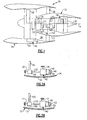
Figure 1 is a highly schematic view of a turbofan gas turbine engine. -
Figure 2a is a schematic view of a first accessory drive gearbox associated with the engine shown inFigure 1 . -
Figure 2b is a schematic view of a second accessory drive gearbox associated with the engine shown inFigure 1 . - An
engine 10 with geared architecture is shown inFigure 1 . A pylon secures theengine 10 to an aircraft. Theengine 10 includes acore nacelle 12 that surrounds a low spool 14 andhigh spool 24 that are rotatable about a common axis A. The low spool 14 supports alow pressure compressor 16 andlow pressure turbine 18. In the example, the low spool 14 drives afan 20 through agear train 22. Thehigh spool 24 supports ahigh pressure compressor 26 andhigh pressure turbine 28. Acombustor 30 is arranged between thehigh pressure compressor 26 andhigh pressure turbine 28. Compressed air fromcompressors combustor 30 and is expanded inturbines - In the example shown, the
engine 10 is a high bypass turbofan arrangement. In one example, the bypass ratio is greater than 10, and the turbofan diameter is substantially larger than the diameter of thelow pressure compressor 16. Thelow pressure turbine 18 has a pressure ratio that is greater than 5:1, in one example. Thegear train 22 is an epicycle gear train, for example, a star gear train, providing a gear reduction ratio of greater than 2.5:1. It should be understood, however, that the above parameters are only exemplary of a contemplated geared architecture engine. That is, the invention is applicable to other engines including direct drive turbofans. - Airflow enters a
fan nacelle 34, which surrounds thecore nacelle 12 andfan 20. Thefan 20 directs air into thecore nacelle 12, which is used to drive theturbines core nacelle 12 once it has been expanded in theturbines core nacelle 12 and atail cone 32. - A
core housing 11 is arranged within thecore nacelle 12 and is supported within thefan nacelle 34 bystructure 36, such as flow exit guide vanes, extending radially inwardly from afan case 35. A generally annularbypass flow path 38 is arranged between the core andfan nacelles fan nacelle 34 bypasses thecore nacelle 12. The bypass flow within thebypass flow path 38 exits thefan nacelle 34 through a fan nozzle exit area at the aft of thefan nacelle 34. - In the example shown in
Figure 1 , at least twoaccessory drive gearboxes gearboxes fuel pump 42,hydraulic pump 44,generator 46,lubrication pump 48,starter 50 and otheraccessory drive components 53. - In one example, one
accessory drive gearbox 40 is arranged in a radial space between thefan case 35 and anexterior surface 33 of thefan nacelle 34. The otheraccessory drive gearbox 140 is arranged in a radial space between thecore housing 11 and anexterior surface 13 of thecore nacelle 12. Bothaccessory drive gearboxes - Referring to
Figures 1 and 2a , theaccessory drive gearbox 40 is driven by the low spool 14. The low spool 14 is coupled to atower shaft 62 with bevel gears, as is known. Thetower shaft 62 drives aninput shaft 52 through anangle gearbox 64, which is mounted to thefan case 35, for example. Theaccessory drive gearbox 40 is supported by thefan case 35, and receives rotational drive from theinput shaft 52. The accessory components shown mounted on theaccessory drive gearboxes Figure 1 , theaccessory drive gearboxes high spools 14, 24 to provide the desired rotational speed to accessory drive components associated with the gearboxes. - Referring to
Figure 2b , theaccessory drive gearbox 140 is driven by thehigh spool 24. Thehigh spool 24 is coupled to atower shaft 162 with bevel gears. Thetower shaft 162 drives aninput shaft 152 through anangle gearbox 164, which is mounted to thecore housing 11, for example. Theaccessory drive gearbox 140 is supported by thecore housing 11, and receives rotational drive from theinput shaft 152. - Although an example embodiment has been disclosed, a worker of ordinary skill in this art would recognize that certain modifications would come within the scope of the claims. For that reason, the following claims should be studied to determine their true scope and content.
Claims (13)
- A turbine engine (10) comprising:first and second gearboxes (40, 140) rotationally coupled to at least one spool (14; 24);accessory drive components including at least two of a fuel pump (42), a hydraulic pump (44), a generator (46), a lubrication pump (48), or a starter (50); andwherein one of the accessory components is mounted to the first gearbox (40), and another of the accessory components is mounted to the second gearbox (140).
- The turbine engine according to claim 1, comprising core (12) and fan (34) nacelles, the core nacelle (12) surrounding the at least one spool (14, 24), the fan nacelle (34) surrounding the core nacelle (12) to provide a bypass flow path between the nacelles (12, 34), and the gearboxes (40, 140) arranged radially within the nacelles.
- The turbine engine according to claim 2, comprising a fan case (35) surrounding a fan (20) that is arranged upstream from the core nacelle (12), and a core housing (11) arranged about the at least one spool (14, 24), the gearboxes (40, 140) supported by at least one of the fan case (35) and the core housing (11).
- The turbine engine according to claim 3, wherein the core nacelle (12) is arranged radially outwardly of the core housing (11) providing a first radial space there between, and the fan nacelle (34) is arranged radially outwardly of fan case (35) providing a second radial space there between, the gearboxes (40, 140) arranged within at least one of the first and second radial spaces.
- The turbine engine according to claim 4, wherein the first and second gearboxes (40, 140) are arranged within the first and second radial spaces, respectively.
- The turbine engine according to claim 4, wherein the core and fan nacelles (12, 34) each include exterior surfaces (13, 33), the gearboxes (40, 140) and their respective accessory drive components (42,.,50) contained radially within the exterior surfaces (13, 33).
- The turbine engine according to any preceding claim, wherein the at least one spool includes low and high spools (14, 24) rotatable about a common axis (A), and the first and second gearboxes (40, 140) are rotationally coupled to the low and high spools (14, 24), respectively.
- The turbine engine according to any preceding claim, wherein the first and second gearboxes (40, 140) are axially spaced from one another.
- The turbine engine according to any preceding claim, wherein the first and second gearboxes (40, 140) are radially spaced from one another.
- The turbine engine according to any preceding claim, wherein at least one of the gearboxes (40, 140) is coupled to the at least one spool (14, 24) by a tower shaft (62, 162), angle box (64, 164) and input shaft (52, 152), the angle box (64, 164) interconnected between the tower (62, 162) and input (64, 164) shafts.
- A turbine engine (10) comprising:first and second gearboxes (40, 140) rotationally coupled to at least one spool (14, 24); anda core nacelle (12) surrounding the at least one spool (14, 24) and surrounded by a fan nacelle (34), the core and fan nacelles (12, 34) each housing one of the first and second gearboxes (40, 140).
- The turbine engine according to claim 11, comprising accessory drive components including at least two of a fuel pump (42), a hydraulic pump (44), a generator (46), a lubrication pump (48), or a starter (50), wherein at least one the accessory components is mounted to the first gearbox (40), and another of the accessory components is mounted to the second gearbox (40).
- The turbine engine according to claim 12, wherein the first gearbox (40) is contained between a core housing (11) and an exterior surface (13) of the core nacelle (12), and the second gearbox (140) is contained between a fan case (35) and an exterior surface (33) of the fan nacelle (34).
Applications Claiming Priority (1)
| Application Number | Priority Date | Filing Date | Title |
|---|---|---|---|
| US11/939,725 US8333554B2 (en) | 2007-11-14 | 2007-11-14 | Split gearbox and nacelle arrangement |
Publications (3)
| Publication Number | Publication Date |
|---|---|
| EP2060759A2 true EP2060759A2 (en) | 2009-05-20 |
| EP2060759A3 EP2060759A3 (en) | 2012-03-21 |
| EP2060759B1 EP2060759B1 (en) | 2016-01-27 |
Family
ID=40276098
Family Applications (1)
| Application Number | Title | Priority Date | Filing Date |
|---|---|---|---|
| EP08253726.7A Revoked EP2060759B1 (en) | 2007-11-14 | 2008-11-14 | Gas turbine with two accessory drive gearboxes |
Country Status (2)
| Country | Link |
|---|---|
| US (1) | US8333554B2 (en) |
| EP (1) | EP2060759B1 (en) |
Cited By (4)
| Publication number | Priority date | Publication date | Assignee | Title |
|---|---|---|---|---|
| WO2014046713A1 (en) | 2012-09-20 | 2014-03-27 | United Technologies Corporation | Geared gas turbine engine accessory gearbox |
| WO2014088925A1 (en) | 2012-12-05 | 2014-06-12 | United Technologies Corporation | Gas turbine engine with a low speed spool driven pump arrangement |
| EP2584171A3 (en) * | 2011-10-19 | 2017-04-19 | United Technologies Corporation | Split accessory drive system |
| EP3647629A1 (en) * | 2018-10-24 | 2020-05-06 | Hamilton Sundstrand Corporation | Gearbox ratio change |
Families Citing this family (27)
| Publication number | Priority date | Publication date | Assignee | Title |
|---|---|---|---|---|
| US9719428B2 (en) * | 2007-11-30 | 2017-08-01 | United Technologies Corporation | Gas turbine engine with pylon mounted accessory drive |
| US20100192595A1 (en) | 2009-01-30 | 2010-08-05 | Robert Joseph Orlando | Gas turbine engine assembly and methods of assembling same |
| US9926849B2 (en) | 2011-06-14 | 2018-03-27 | Honeywell International Inc. | Transverse mounted accessory gearbox |
| US9145834B2 (en) | 2011-06-14 | 2015-09-29 | Honeywell International Inc. | Transverse mounted accessory gearbox |
| US9140194B2 (en) * | 2012-01-11 | 2015-09-22 | Honeywell International Inc. | Gas turbine engine starter-generator with integrated lube oil scavenge functionality |
| US9121346B2 (en) | 2012-03-14 | 2015-09-01 | United Technologies Corporation | Pump system for TMS AOC reduction |
| US9151224B2 (en) | 2012-03-14 | 2015-10-06 | United Technologies Corporation | Constant-speed pump system for engine thermal management system AOC reduction and environmental control system loss elimination |
| US9194294B2 (en) * | 2012-05-07 | 2015-11-24 | United Technologies Corporation | Gas turbine engine oil tank |
| JP5568596B2 (en) * | 2012-05-30 | 2014-08-06 | 川崎重工業株式会社 | Aircraft engine gearbox integrated power generator |
| US9790861B2 (en) | 2012-09-28 | 2017-10-17 | United Technologies Corporation | Gas turbine engine having support structure with swept leading edge |
| US20140090386A1 (en) * | 2012-09-28 | 2014-04-03 | United Technologies Corporation | Geared turbofan with fan and core mounted accessory gearboxes |
| US9297314B2 (en) * | 2012-12-19 | 2016-03-29 | United Technologies Corporation | Gas turbine engine with accessory gear box |
| US9500133B2 (en) * | 2012-12-23 | 2016-11-22 | United Technologies Corporation | Mount with an axial upstream linkage for connecting a gearbox to a turbine engine case |
| US9624827B2 (en) | 2013-03-15 | 2017-04-18 | United Technologies Corporation | Thrust efficient turbofan engine |
| WO2014143294A1 (en) * | 2013-03-15 | 2014-09-18 | United Technologies Corporation | Distributed engine accessory drive |
| US10724479B2 (en) | 2013-03-15 | 2020-07-28 | United Technologies Corporation | Thrust efficient turbofan engine |
| FR3007458B1 (en) * | 2013-06-21 | 2017-11-10 | Snecma | IMPROVED TURBOMACHINE INTERMEDIATE CASE AND ACCESSORY BOX DRIVE ASSEMBLY |
| WO2015047577A1 (en) * | 2013-09-26 | 2015-04-02 | United Technologies Corporation | Gas turbine engine with split lubrication system |
| WO2015065720A1 (en) * | 2013-11-01 | 2015-05-07 | United Technologies Corporation | Auxiliary oil pump for gas turbine engine gear reduction |
| US10746181B2 (en) * | 2016-08-22 | 2020-08-18 | Raytheon Technologies Corporation | Variable speed boost compressor for gas turbine engine cooling air supply |
| US10823080B2 (en) | 2017-05-31 | 2020-11-03 | General Electric Company | Dual accessory gearbox |
| FR3110939B1 (en) * | 2020-05-27 | 2022-09-09 | Safran Trans Systems | TURBOMACHINE EQUIPPED WITH ELECTRIC MACHINES COUPLED TO A COUPLING SURFACE |
| DE102020117254A1 (en) | 2020-06-30 | 2021-12-30 | Rolls-Royce Deutschland Ltd & Co Kg | Gas turbine engine and aircraft with a gas turbine engine |
| DE102020117255A1 (en) | 2020-06-30 | 2021-12-30 | Rolls-Royce Deutschland Ltd & Co Kg | Gas turbine engine and aircraft with a gas turbine engine |
| US12123373B2 (en) * | 2020-07-17 | 2024-10-22 | Rtx Corporation | Geared turbofan with over-speed protection |
| US20250075662A1 (en) * | 2023-09-05 | 2025-03-06 | General Electric Company | Turbine Engine having First and Second Accessory Gearboxes |
| US12209557B1 (en) * | 2023-11-30 | 2025-01-28 | General Electric Company | Gas turbine engine with forward swept outlet guide vanes |
Family Cites Families (24)
| Publication number | Priority date | Publication date | Assignee | Title |
|---|---|---|---|---|
| US2978869A (en) * | 1956-11-01 | 1961-04-11 | Bristol Siddeley Engines Ltd | Engine accessory mounting arrangements |
| US3286543A (en) | 1963-07-12 | 1966-11-22 | Fairchild Hiller Corp | Combined turbine and hydromechanical transmission |
| US3806067A (en) | 1971-08-30 | 1974-04-23 | Gen Electric | Area ruled nacelle |
| US4121138A (en) | 1977-05-31 | 1978-10-17 | Bell & Howell Company | Servo system |
| US4593523A (en) | 1980-12-17 | 1986-06-10 | Allied Corporation | Method and apparatus for acceleration limiting a gas turbine engine |
| US4507915A (en) | 1981-04-30 | 1985-04-02 | Allied Corporation | Stall detector and surge prevention feature for a gas turbine engine |
| DE3622022A1 (en) | 1986-07-01 | 1988-01-07 | Kloeckner Humboldt Deutz Ag | GAS TURBINE ENGINE |
| GB2234035B (en) * | 1989-07-21 | 1993-05-12 | Rolls Royce Plc | A reduction gear assembly and a gas turbine engine |
| US5097658A (en) | 1989-09-21 | 1992-03-24 | Allied-Signal Inc. | Integrated power unit control apparatus and method |
| US5349814A (en) | 1993-02-03 | 1994-09-27 | General Electric Company | Air-start assembly and method |
| US5309029A (en) | 1993-06-18 | 1994-05-03 | The United States Of America As Represented By The Secretary Of The Air Force | Aircraft power unit with elective mechanical coupling |
| GB9313905D0 (en) | 1993-07-06 | 1993-08-25 | Rolls Royce Plc | Shaft power transfer in gas turbine engines |
| ATE193755T1 (en) | 1996-04-30 | 2000-06-15 | Steyr Daimler Puch Ag | METHOD FOR FINE CONTROL OF A HYDROSTATIC-MECHANICAL POWER-SPLIT TRANSMISSION |
| US5806805A (en) | 1996-08-07 | 1998-09-15 | The Boeing Company | Fault tolerant actuation system for flight control actuators |
| US6158210A (en) | 1998-12-03 | 2000-12-12 | General Electric Company | Gear driven booster |
| GB9910393D0 (en) | 1999-05-05 | 1999-07-07 | Lucas Ind Plc | Electrical generator,an aero-engine including such a generator and an aircraft including such a generator |
| FR2826052B1 (en) | 2001-06-19 | 2003-12-19 | Snecma Moteurs | RELIEF DEVICE FOR THE IGNITION OF A SELF-ROTATING TURBO-JET |
| GB0128662D0 (en) | 2001-11-30 | 2002-01-23 | Rolls Royce Plc | Improvements in or relating to generator arrangements |
| GB0315894D0 (en) | 2003-07-08 | 2003-08-13 | Rolls Royce Plc | Aircraft engine arrangement |
| FR2863312B1 (en) * | 2003-12-09 | 2008-07-04 | Snecma Moteurs | DOUBLE-BODY TURBOREACTOR WITH MEANS FOR DRIVING ACCESSORY MACHINES |
| US7055330B2 (en) | 2004-02-25 | 2006-06-06 | United Technologies Corp | Apparatus for driving an accessory gearbox in a gas turbine engine |
| DE102004023569A1 (en) | 2004-05-13 | 2005-12-08 | Mtu Aero Engines Gmbh | Aircraft engine |
| FR2882096B1 (en) * | 2005-02-11 | 2012-04-20 | Snecma Moteurs | DUAL-BODY TURBOMOTEUR WITH MOTION-TENSIONING MEANS ON LOW-PRESSURE, HIGH-PRESSURE ROTORS, TURBOMOTING MOTION-TENSIONING MODULE, AND TURBOMOTING MOUNTING METHOD |
| US20090188334A1 (en) * | 2008-01-25 | 2009-07-30 | United Technologies Corp. | Accessory Gearboxes and Related Gas Turbine Engine Systems |
-
2007
- 2007-11-14 US US11/939,725 patent/US8333554B2/en active Active
-
2008
- 2008-11-14 EP EP08253726.7A patent/EP2060759B1/en not_active Revoked
Cited By (8)
| Publication number | Priority date | Publication date | Assignee | Title |
|---|---|---|---|---|
| EP2584171A3 (en) * | 2011-10-19 | 2017-04-19 | United Technologies Corporation | Split accessory drive system |
| WO2014046713A1 (en) | 2012-09-20 | 2014-03-27 | United Technologies Corporation | Geared gas turbine engine accessory gearbox |
| EP2898205A4 (en) * | 2012-09-20 | 2015-10-28 | United Technologies Corp | AUXILIARY GEARBOX FOR GAS TURBINE MOTOR |
| US10184404B2 (en) | 2012-09-20 | 2019-01-22 | United Technologies Corporation | Geared gas turbine engine accessory gearbox |
| WO2014088925A1 (en) | 2012-12-05 | 2014-06-12 | United Technologies Corporation | Gas turbine engine with a low speed spool driven pump arrangement |
| EP2929164A4 (en) * | 2012-12-05 | 2015-12-30 | United Technologies Corp | GAS TURBINE WITH A PUMP ARRANGEMENT DRIVEN BY A LOW SPEED COIL |
| EP3647629A1 (en) * | 2018-10-24 | 2020-05-06 | Hamilton Sundstrand Corporation | Gearbox ratio change |
| US11168577B2 (en) | 2018-10-24 | 2021-11-09 | Hamilton Sundstrand Corporation | Gearbox ratio change |
Also Published As
| Publication number | Publication date |
|---|---|
| US20090123274A1 (en) | 2009-05-14 |
| EP2060759B1 (en) | 2016-01-27 |
| EP2060759A3 (en) | 2012-03-21 |
| US8333554B2 (en) | 2012-12-18 |
Similar Documents
| Publication | Publication Date | Title |
|---|---|---|
| EP2060759B1 (en) | Gas turbine with two accessory drive gearboxes | |
| US10001059B2 (en) | Accessory gearbox with tower shaft removal capability | |
| EP2065585B1 (en) | Gas turbine engine with pylon mounted accessory drive | |
| EP2820249B1 (en) | Gas turbine engine with fan-tied inducer section and multiple low pressure turbine sections | |
| US20130125561A1 (en) | Geared turbofan with distributed accessory gearboxes | |
| US8490411B2 (en) | Axial accessory gearbox | |
| US8347637B2 (en) | Accessory gearbox with internal layshaft | |
| EP2935788B1 (en) | Low pressure ratio fan engine having a dimensional relationship between inlet and fan size | |
| US10590854B2 (en) | Geared gas turbine engine | |
| EP3273033B1 (en) | Turbine shaft power take-off | |
| EP3431738B1 (en) | Tangential drive for gas turbine engine accessories | |
| US20120117940A1 (en) | Gas turbine engine with pylon mounted accessory drive | |
| EP4215737B1 (en) | Dual spool power extraction with superposition gearbox | |
| US10677159B2 (en) | Gas turbine engine including a dual-speed split compressor | |
| US20180080411A1 (en) | Gas turbine engine | |
| EP4261400A1 (en) | Gearbox arrangement for close to constant speed accessories | |
| EP2617965A2 (en) | Gas turbine engine with pylon mounted accessory drive | |
| US12123310B2 (en) | Gas turbine engine with idle thrust ratio | |
| EP3696392B2 (en) | Angle accessory gearbox for gas turbine engine | |
| EP2904210A2 (en) | Gas turbine engine with forward moment arm | |
| WO2013165771A1 (en) | Geared turbofan with distributed accessory gearboxes |
Legal Events
| Date | Code | Title | Description |
|---|---|---|---|
| PUAI | Public reference made under article 153(3) epc to a published international application that has entered the european phase |
Free format text: ORIGINAL CODE: 0009012 |
|
| AK | Designated contracting states |
Kind code of ref document: A2 Designated state(s): AT BE BG CH CY CZ DE DK EE ES FI FR GB GR HR HU IE IS IT LI LT LU LV MC MT NL NO PL PT RO SE SI SK TR |
|
| AX | Request for extension of the european patent |
Extension state: AL BA MK RS |
|
| PUAL | Search report despatched |
Free format text: ORIGINAL CODE: 0009013 |
|
| AK | Designated contracting states |
Kind code of ref document: A3 Designated state(s): AT BE BG CH CY CZ DE DK EE ES FI FR GB GR HR HU IE IS IT LI LT LU LV MC MT NL NO PL PT RO SE SI SK TR |
|
| AX | Request for extension of the european patent |
Extension state: AL BA MK RS |
|
| RIC1 | Information provided on ipc code assigned before grant |
Ipc: F02C 7/32 20060101AFI20120214BHEP Ipc: F02C 7/36 20060101ALI20120214BHEP |
|
| 17P | Request for examination filed |
Effective date: 20120921 |
|
| 17Q | First examination report despatched |
Effective date: 20121022 |
|
| AKX | Designation fees paid |
Designated state(s): DE GB |
|
| GRAP | Despatch of communication of intention to grant a patent |
Free format text: ORIGINAL CODE: EPIDOSNIGR1 |
|
| INTG | Intention to grant announced |
Effective date: 20150713 |
|
| GRAS | Grant fee paid |
Free format text: ORIGINAL CODE: EPIDOSNIGR3 |
|
| GRAA | (expected) grant |
Free format text: ORIGINAL CODE: 0009210 |
|
| AK | Designated contracting states |
Kind code of ref document: B1 Designated state(s): DE GB |
|
| REG | Reference to a national code |
Ref country code: GB Ref legal event code: FG4D |
|
| REG | Reference to a national code |
Ref country code: DE Ref legal event code: R096 Ref document number: 602008042145 Country of ref document: DE |
|
| RAP2 | Party data changed (patent owner data changed or rights of a patent transferred) |
Owner name: UNITED TECHNOLOGIES CORPORATION |
|
| REG | Reference to a national code |
Ref country code: DE Ref legal event code: R026 Ref document number: 602008042145 Country of ref document: DE |
|
| PLBI | Opposition filed |
Free format text: ORIGINAL CODE: 0009260 |
|
| 26 | Opposition filed |
Opponent name: SAFRAN AIRCRAFT ENGINES Effective date: 20161027 |
|
| PLAX | Notice of opposition and request to file observation + time limit sent |
Free format text: ORIGINAL CODE: EPIDOSNOBS2 |
|
| PLBB | Reply of patent proprietor to notice(s) of opposition received |
Free format text: ORIGINAL CODE: EPIDOSNOBS3 |
|
| REG | Reference to a national code |
Ref country code: DE Ref legal event code: R082 Ref document number: 602008042145 Country of ref document: DE Representative=s name: SCHMITT-NILSON SCHRAUD WAIBEL WOHLFROM PATENTA, DE |
|
| REG | Reference to a national code |
Ref country code: DE Ref legal event code: R082 Ref document number: 602008042145 Country of ref document: DE Representative=s name: SCHMITT-NILSON SCHRAUD WAIBEL WOHLFROM PATENTA, DE Ref country code: DE Ref legal event code: R081 Ref document number: 602008042145 Country of ref document: DE Owner name: UNITED TECHNOLOGIES CORP. (N.D.GES.D. STAATES , US Free format text: FORMER OWNER: UNITED TECHNOLOGIES CORPORATION, HARTFORD, CONN., US |
|
| RDAF | Communication despatched that patent is revoked |
Free format text: ORIGINAL CODE: EPIDOSNREV1 |
|
| REG | Reference to a national code |
Ref country code: DE Ref legal event code: R064 Ref document number: 602008042145 Country of ref document: DE Ref country code: DE Ref legal event code: R103 Ref document number: 602008042145 Country of ref document: DE |
|
| PGFP | Annual fee paid to national office [announced via postgrant information from national office to epo] |
Ref country code: DE Payment date: 20171019 Year of fee payment: 10 |
|
| PGFP | Annual fee paid to national office [announced via postgrant information from national office to epo] |
Ref country code: GB Payment date: 20171020 Year of fee payment: 10 |
|
| RDAG | Patent revoked |
Free format text: ORIGINAL CODE: 0009271 |
|
| STAA | Information on the status of an ep patent application or granted ep patent |
Free format text: STATUS: PATENT REVOKED |
|
| 27W | Patent revoked |
Effective date: 20180113 |
|
| GBPR | Gb: patent revoked under art. 102 of the ep convention designating the uk as contracting state |
Effective date: 20180113 |