EP2060668A1 - Two-part damper pin - Google Patents
Two-part damper pin Download PDFInfo
- Publication number
- EP2060668A1 EP2060668A1 EP07124183A EP07124183A EP2060668A1 EP 2060668 A1 EP2060668 A1 EP 2060668A1 EP 07124183 A EP07124183 A EP 07124183A EP 07124183 A EP07124183 A EP 07124183A EP 2060668 A1 EP2060668 A1 EP 2060668A1
- Authority
- EP
- European Patent Office
- Prior art keywords
- sleeve
- rod
- damper
- flange
- washing machine
- Prior art date
- Legal status (The legal status is an assumption and is not a legal conclusion. Google has not performed a legal analysis and makes no representation as to the accuracy of the status listed.)
- Granted
Links
- 238000005406 washing Methods 0.000 claims abstract description 22
- 230000015572 biosynthetic process Effects 0.000 claims description 4
- 230000037431 insertion Effects 0.000 claims description 3
- 238000003780 insertion Methods 0.000 claims description 3
- 230000003416 augmentation Effects 0.000 claims description 2
- 238000005192 partition Methods 0.000 claims description 2
- 238000005755 formation reaction Methods 0.000 claims 2
- 238000006073 displacement reaction Methods 0.000 description 5
- 238000004519 manufacturing process Methods 0.000 description 1
- 238000000638 solvent extraction Methods 0.000 description 1
- 230000002269 spontaneous effect Effects 0.000 description 1
Images


Classifications
-
- D—TEXTILES; PAPER
- D06—TREATMENT OF TEXTILES OR THE LIKE; LAUNDERING; FLEXIBLE MATERIALS NOT OTHERWISE PROVIDED FOR
- D06F—LAUNDERING, DRYING, IRONING, PRESSING OR FOLDING TEXTILE ARTICLES
- D06F37/00—Details specific to washing machines covered by groups D06F21/00 - D06F25/00
- D06F37/20—Mountings, e.g. resilient mountings, for the rotary receptacle, motor, tub or casing; Preventing or damping vibrations
Definitions
- the present invention relates to the connection structure of a damper to the machine body and tub, said damper being used in washing machines for attenuating the vibration occurring as a result of the revolving drum.
- dampers used in washing machines are connected to the machine body and drum by means of damper pins.
- dampers are provided with annular cross-sectioned slots at both of their ends. Said damper pins are placed into these slots and into other annular cross-sectioned slots provided on the machine body and tub that cooperate with the former slots.
- an apparatus for connecting the tube and machine body to the damper is composed of a sleeve and a pin.
- the sleeve is inserted to the damper slot, whereas the pin is inserted to the sleeve.
- the insertion of the damper pin into the sleeve is achieved by displacing it from the starting position up to the locking position, and the damper pin is fixed axially with respect to the sleeve at the locking position.
- the complex structure of the damper pin disclosed in this application enhances the manufacture costs. Additionally, any small axial back and forth displacements of the damper sleeve can not be avoided.
- the pin disclosed here is not resistant against flexion and therefore lacks in counterbalancing the vertical forces coming from the damper and so becomes flexed. And any flexion to occur on the pin leads to vibration and noise on the washing machine.
- the damper pin is composed of a sleeve and a rod within said sleeve.
- the external surface and the interior of the sleeve are of a cylindrical formation.
- the interior is of a structure that extends in a lengthwise manner throughout in the sleeve.
- At least one cut is provided at one end of the sleeve so as to partition the sleeve to a certain amount lengthwise.
- At the side provided with such cuts and close to the tip are provided protrusions on each part formed by said cuts, said protrusions being formed with the external surface expanding outwards a certain amount and said protrusions surrounding the sleeve.
- the rod it is a cylindrical piece formed so as to be positioned on the internal surface of sleeve.
- the sleeve For assembling the damper pin into the damper slot, first the sleeve is inserted into the damper slot. Since the external diameter formed by the outset protrusions at the sleeve is larger than the internal diameter of the slot, the sleeve flexes inwardly by means of said cuts as it is inserted to the slot. Once the sleeve is fastened to the slot completely, the protrusions become projected out of the slot. In this case, the sleeve becomes flexed outwardly from the side provided with said cuts. Thanks to this flexible structure of the sleeve, the external surface may also be optionally embodied so as to become jammed within the slot. Thereafter the rod is driven forward within the interior of the sleeve.
- the objective of the present invention is to provide a structure which is not flexible against forces to come from the damper.
- Another objective of the present invention is to provide a two-part damper pin to facilitate the damper assembly to the tub and body of washing machines.
- a further objective of the present invention is to provide an assembly of said two-part damper pin into the damper slot without slack and thus to prevent the vibrations of a revolving drum from affecting the remaining parts of the washing machine.
- Yet another objective of the present invention is to avoid the loosening and removal of said two-part damper pin from the damper slot while the washing machine is running.
- Yet a further objective of the present invention is to provide an inexpensive and secure damper connection.
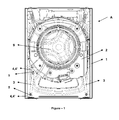
- the subject washing machine (A) as illustrated in Figure 1 and Figure 2 comprises a machine body (1); a tube (2) within said body; at least one damper (3) connected to the connection lugs (4, 4') on the body (1) and tub (2); and damper pin (5) providing the connection of one each end of the damper (3) to each connection lugs (4, 4').
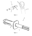
- Figure 3 illustrates from on side how a damper pin (5) is placed on the connection lugs (4, 4') and on the slot (8) provided at one end of the damper (3).
- the connection lug (4) is not shown
- the below detailed sleeve (6) and the rod (7) within said sleeve (6) of the damper pin (5) are together placed on the connection lugs (4, 4') and damper slot (8).
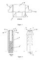
- the damper pin (5) as illustrated in figures 5 and 6 is composed of a sleeve (6) and a rod (7) within said sleeve.
- the external surface (61) and the interior (62) of said sleeve is of a cylindrical form.
- the interior (62) is of a structure that extends in a lengthwise manner throughout in the sleeve (6).
- a flange (63) is provided at one end of the sleeve (6) so as to extend outwardly and surround the sleeve (6).
- At the other end of said sleeve (6) is provided at least one cut (64), partitioning the sleeve (6) to a certain amount lengthwise.
- protrusions (65) on each part formed by said cuts (64), said protrusions being formed with the external surface (61) expanding outwards a certain amount and said protrusions surrounding the sleeve (6).
- other protrusions (66) on each part formed by said cuts (64), said protrusions (66) being formed with the internal surface (62) expanding inwards a certain amount and surrounding the interior of said sleeve (6).
- the rod (7) With respect to the rod (7), it has a cylindrical structure formed so as to be positioned on the internal surface (62) of the sleeve (6).
- One axially-extending hole (72) is provided on the front part (71) of the rod (7).
- at least one support rib (74) is positioned that is formed in a lengthwise manner.
- At the tip of the rear part (73) and on each rib (74) are formed at least one flange (75), producing a sidewise expansion and surrounding the rod (7).
- At least one recession (78) is provided at a portion close to the front part's (71) tip on the exterior of the rod (7) so as to correspond to each sleeve protrusion (66).
- a flange (77) formed with a small diameter augmentation is provided around the tip portion of the rod (7) and in front of the recession (78).
- the foremost tip of the rod (7) preceding the flange is conical to a certain extent, narrowing towards the tip.
- the function of this conical formation is to facilitate the rod's (7) assembly to the sleeve (6) by providing a centering guide.
- the sleeve (6) of the pin (5) is assembled to the connection lugs (4, 4') and damper slot (8).
- the side accommodating the rod (7) flange (77) is inserted into the interior (62) of the sleeve (6) from the side accommodating the sleeve flange (63) (as illustrated in Figure 7 ).
- the diameter of the rod (7) flange (77) is larger than the diameter of the sleeve (6) interior (62) so as to allow a fast insertion of the rod's (7) tip, during this first assembly the rod's (7) tip first is leaned on the interior (62), and as long as the rod (7) is kept pushed, the rod's (7) tip advances and with each protrusion (66) settling into the respective recession (78) (illustrated in Figure 8 ), the assembly is completed. In this manner, thanks to the flange (77) provided on the rod (7), any spontaneous removal of the rod (7) from the sleeve is avoided.
- any further advancement of the sleeve (6) is avoided by means of the flange (63) leaning against the side surface of the connection lug (4). And any further advancement of the rod (7) is ensured by means of the rod flange (75) leaning against the side surface of the flange (63). With the rod (7) becoming entirely settled into the interior (62), the inward flexion and the removal of the sleeve (6) from the connection lugs (4, 4') and slot (8) is avoided. Even with the lugs (4, 4') and slot (8) becoming jammed between the flange (63) and conical protrusions (65), not only the radial displacement of the damper pin (5), as was indicated above, but also the axial displacement is blocked.
Landscapes
- Engineering & Computer Science (AREA)
- Textile Engineering (AREA)
- Main Body Construction Of Washing Machines And Laundry Dryers (AREA)
- Vehicle Body Suspensions (AREA)
Abstract
Description
- The present invention relates to the connection structure of a damper to the machine body and tub, said damper being used in washing machines for attenuating the vibration occurring as a result of the revolving drum.
- With respect to the background art, dampers used in washing machines are connected to the machine body and drum by means of damper pins. Such dampers are provided with annular cross-sectioned slots at both of their ends. Said damper pins are placed into these slots and into other annular cross-sectioned slots provided on the machine body and tub that cooperate with the former slots.
- Concerning the published patent application
US2005183472 of the background art, in this document is disclosed a damper assembly performed by means of a single-part damper pin in front-loaded washing machines. According to this application, the lower lug of the damper is connected to base lugs so that the lower lug is supported by said base lugs. Said single-part damper pin is further equipped with an elastic clips. Following the assembly thanks to the clips, the single-part damper pin's displacement is avoided on the opposite direction of assembly. The structure of the damper pin disclosed here does not allow an assembly without slack into the damper slot. Furthermore, the pin disclosed here is not resistant against flexion and therefore lacks in counterbalancing the vertical forces from the damper and so becomes flexed. Any flexion to occur on the pin leads to vibration and noise on the washing machine. - Regarding the published patent application
DE102005008239 , here is disclosed an apparatus for connecting the tube and machine body to the damper. This apparatus is composed of a sleeve and a pin. The sleeve is inserted to the damper slot, whereas the pin is inserted to the sleeve. The insertion of the damper pin into the sleeve is achieved by displacing it from the starting position up to the locking position, and the damper pin is fixed axially with respect to the sleeve at the locking position. The complex structure of the damper pin disclosed in this application enhances the manufacture costs. Additionally, any small axial back and forth displacements of the damper sleeve can not be avoided. Furthermore, the pin disclosed here is not resistant against flexion and therefore lacks in counterbalancing the vertical forces coming from the damper and so becomes flexed. And any flexion to occur on the pin leads to vibration and noise on the washing machine. - The damper pin is composed of a sleeve and a rod within said sleeve. The external surface and the interior of the sleeve are of a cylindrical formation. The interior is of a structure that extends in a lengthwise manner throughout in the sleeve. At least one cut is provided at one end of the sleeve so as to partition the sleeve to a certain amount lengthwise. At the side provided with such cuts and close to the tip are provided protrusions on each part formed by said cuts, said protrusions being formed with the external surface expanding outwards a certain amount and said protrusions surrounding the sleeve. With respect to the rod, it is a cylindrical piece formed so as to be positioned on the internal surface of sleeve.
- For assembling the damper pin into the damper slot, first the sleeve is inserted into the damper slot. Since the external diameter formed by the outset protrusions at the sleeve is larger than the internal diameter of the slot, the sleeve flexes inwardly by means of said cuts as it is inserted to the slot. Once the sleeve is fastened to the slot completely, the protrusions become projected out of the slot. In this case, the sleeve becomes flexed outwardly from the side provided with said cuts. Thanks to this flexible structure of the sleeve, the external surface may also be optionally embodied so as to become jammed within the slot. Thereafter the rod is driven forward within the interior of the sleeve. With the rod becoming entirely settled in the interior, the inward flexion and the removal of the sleeve is avoided. In this manner a structure is obtained which does not flex against forces to come from the damper used for attenuating the vibrations resulting from the revolving drum within the tub.
- The objective of the present invention is to provide a structure which is not flexible against forces to come from the damper.
- Another objective of the present invention is to provide a two-part damper pin to facilitate the damper assembly to the tub and body of washing machines.
- A further objective of the present invention is to provide an assembly of said two-part damper pin into the damper slot without slack and thus to prevent the vibrations of a revolving drum from affecting the remaining parts of the washing machine.
- Yet another objective of the present invention is to avoid the loosening and removal of said two-part damper pin from the damper slot while the washing machine is running.
- Yet a further objective of the present invention is to provide an inexpensive and secure damper connection.
- Exemplary embodiments of the subject washing machine and the two-part damper pin used in such machine are illustrated in annexed figures as described below in brief.
-
Figure 1 is a front view of the interior of a washing machine. -
Figure 2 is a front perspective view of the interior of a washing machine. -
Figure 3 is a side view of the assembly manner of said two-part damper pin to the damper and machine's connection lug. -
Figure 4 is a perspective view of the assembly manner of said two-part damper pin to the damper. -
Figure 5 is a perspective view of the two-part damper pin. -
Figure 6 is a normal and cross-sectional side view of said two-part damper pin. -
Figure 7 is a detailed cross-sectional view of the interconnection of the sleeve and rod composing the two-part damper pin. -
Figure 8 is a cross-sectional view of the full assembled form of the sleeve and rod. - The parts in said figures are individually enumerated as following.
- Washing machine (A)
- Machine body (1)
- Tub (2)
- Damper (3)
- Connection lug (4, 4')
- Two-part damper pin (5)
- Sleeve (6)
- Rod (7)
- Damper slot (8)
- Drum (9)
- External surface (61)
- Interior (62)
- Flange (63)
- Cut (64)
- Protrusion (65)
- Protrusion (66)
- Front part (71)
- Hole (72)
- Rear part (73)
- Rib (74)
- Flange (75)
- Flange (77)
- Recession (78)
- The subject washing machine (A) as illustrated in
Figure 1 andFigure 2 comprises a machine body (1); a tube (2) within said body; at least one damper (3) connected to the connection lugs (4, 4') on the body (1) and tub (2); and damper pin (5) providing the connection of one each end of the damper (3) to each connection lugs (4, 4'). -
Figure 3 illustrates from on side how a damper pin (5) is placed on the connection lugs (4, 4') and on the slot (8) provided at one end of the damper (3). In this connection manner illustrated inFigure 4 (the connection lug (4) is not shown), the below detailed sleeve (6) and the rod (7) within said sleeve (6) of the damper pin (5) are together placed on the connection lugs (4, 4') and damper slot (8). - As indicated above, the damper pin (5) as illustrated in
figures 5 and6 is composed of a sleeve (6) and a rod (7) within said sleeve. The external surface (61) and the interior (62) of said sleeve is of a cylindrical form. The interior (62) is of a structure that extends in a lengthwise manner throughout in the sleeve (6). A flange (63) is provided at one end of the sleeve (6) so as to extend outwardly and surround the sleeve (6). At the other end of said sleeve (6) is provided at least one cut (64), partitioning the sleeve (6) to a certain amount lengthwise. At the side provided with such cuts (64) and close to the tip are provided protrusions (65) on each part formed by said cuts (64), said protrusions being formed with the external surface (61) expanding outwards a certain amount and said protrusions surrounding the sleeve (6). In a similar manner, at the side provided with such cuts (64) and close to the tip are provided other protrusions (66) on each part formed by said cuts (64), said protrusions (66) being formed with the internal surface (62) expanding inwards a certain amount and surrounding the interior of said sleeve (6). - With respect to the rod (7), it has a cylindrical structure formed so as to be positioned on the internal surface (62) of the sleeve (6). One axially-extending hole (72) is provided on the front part (71) of the rod (7). And at the rear part (73) of the rod, at least one support rib (74) is positioned that is formed in a lengthwise manner. At the tip of the rear part (73) and on each rib (74) are formed at least one flange (75), producing a sidewise expansion and surrounding the rod (7). At least one recession (78) is provided at a portion close to the front part's (71) tip on the exterior of the rod (7) so as to correspond to each sleeve protrusion (66). A flange (77) formed with a small diameter augmentation is provided around the tip portion of the rod (7) and in front of the recession (78). The foremost tip of the rod (7) preceding the flange is conical to a certain extent, narrowing towards the tip. The function of this conical formation is to facilitate the rod's (7) assembly to the sleeve (6) by providing a centering guide.
- In order to assembly the damper pin (5) to the connection lugs (4, 4') and damper slot (8), first the sleeve (6) of the pin (5) is assembled to the connection lugs (4, 4') and damper slot (8). In a second step, the side accommodating the rod (7) flange (77) is inserted into the interior (62) of the sleeve (6) from the side accommodating the sleeve flange (63) (as illustrated in
Figure 7 ). Since the diameter of the rod (7) flange (77) is larger than the diameter of the sleeve (6) interior (62) so as to allow a fast insertion of the rod's (7) tip, during this first assembly the rod's (7) tip first is leaned on the interior (62), and as long as the rod (7) is kept pushed, the rod's (7) tip advances and with each protrusion (66) settling into the respective recession (78) (illustrated inFigure 8 ), the assembly is completed. In this manner, thanks to the flange (77) provided on the rod (7), any spontaneous removal of the rod (7) from the sleeve is avoided. - Any further advancement of the sleeve (6) is avoided by means of the flange (63) leaning against the side surface of the connection lug (4). And any further advancement of the rod (7) is ensured by means of the rod flange (75) leaning against the side surface of the flange (63). With the rod (7) becoming entirely settled into the interior (62), the inward flexion and the removal of the sleeve (6) from the connection lugs (4, 4') and slot (8) is avoided. Even with the lugs (4, 4') and slot (8) becoming jammed between the flange (63) and conical protrusions (65), not only the radial displacement of the damper pin (5), as was indicated above, but also the axial displacement is blocked. In the backward displacement of the sleeve (6) together with the rod (7), the protrusions (65) lean against the lateral surface of the connection lug so that any unintentional removal of the damper pin (5) from the slot (8) and lugs (4, 4') is avoided.
Claims (8)
- A washing machine (A) comprising a machine body (1); a tube (2) within said body; at least one damper (3) connected to the connection lugs (4, 4') on the body (1) and tub (2); and damper pin (5) consisting of a sleeve (6) and a rod (7) within said sleeve and providing the connection of each connection lug (4, 4') to the slot (8) provided at each end of the damper (3), wherein
the external surface (61) and the throughout interior (62) of said sleeve have cylindrical formations; said cylindrical rod (7) is placed into said interior (62); at least one cut (64) is formed on one end of the sleeve (6) so as to partition said sleeve (6) to a certain lengthwise extent; protrusions (65) expanding outwardly in a conical manner to a certain extent are provided on each flexible part produced by said cuts (64); and an outwardly-expanding flange (63) is provided on the other end of the sleeve (6); characterized in that
protrusions (66), which the internal surface (62) produces by becoming narrowed inwards to a certain amount, are provided at the tip of each part formed by said cuts (64) on said sleeve (6); said rod (7) comprises at a side close to the tip of its front part (71) on its exterior at least one recession (78) corresponding to each sleeve protrusion (66);
said protrusions (65) and flange (63) are leaned against the outfacing lateral surfaces of lugs (4, 4') and at least one protrusion (66) at the sleeve (6) becomes introduced or settled into the recession (78) at the rod (7), when the damper pin (5) is assembled to the connection lugs (4, 4') and damper slot (8). - A washing machine (A) according to Claim 1, wherein said rod (7) comprises at least one support rib (74) formed in a lengthwise manner at the rear part (73) thereof.
- A washing machine (A) according to Claim 1, wherein a flange (77) is formed with a small diameter augmentation around the tip portion of said rod (7) in front of the recession (78).
- A washing machine (A) according to Claim 1, wherein the foremost tip portion of said rod (7) is conical to a certain extent so as to become narrower toward the end.
- A washing machine (A) according to Claim 1, wherein the diameter of the rod flange (77) is kept larger than the diameter of the sleeve's (6) internal surface (62) so as to ensure a tight insertion of the rod's (7) tip, in order to assemble together said sleeve (6) and rod (7), and to provide a more sound structure against damper loads.
- A washing machine (A) according to Claim 1, wherein said rod (7) comprises on its front part (71) one hole (72) extending along the rod axis (7).
- A washing machine (A) according to Claim 1, wherein at least one flange (75), which expands outwardly and surrounds said rod (7) is provided at the tip of the rod's (7) rear part (73).
- A washing machine (A) according to Claim 7, characterized in that said rod flange (75) has a formation to lean against said sleeve flange (63).
Applications Claiming Priority (1)
| Application Number | Priority Date | Filing Date | Title |
|---|---|---|---|
| TR2007/07811U TR200707811U (en) | 2007-11-13 | 2007-11-13 | Two-piece shock absorber pin. |
Publications (2)
| Publication Number | Publication Date |
|---|---|
| EP2060668A1 true EP2060668A1 (en) | 2009-05-20 |
| EP2060668B1 EP2060668B1 (en) | 2010-03-17 |
Family
ID=40445691
Family Applications (1)
| Application Number | Title | Priority Date | Filing Date |
|---|---|---|---|
| EP07124183A Revoked EP2060668B1 (en) | 2007-11-13 | 2007-12-31 | Two-part damper pin |
Country Status (6)
| Country | Link |
|---|---|
| EP (1) | EP2060668B1 (en) |
| AT (1) | ATE461309T1 (en) |
| DE (1) | DE602007005383D1 (en) |
| ES (1) | ES2341377T3 (en) |
| PT (1) | PT2060668E (en) |
| TR (1) | TR200707811U (en) |
Cited By (1)
| Publication number | Priority date | Publication date | Assignee | Title |
|---|---|---|---|---|
| US11247252B2 (en) | 2015-07-16 | 2022-02-15 | Outokumpu Oyj | Method for manufacturing a component of austenitic TWIP or TRIP/TWIP steel |
Citations (5)
| Publication number | Priority date | Publication date | Assignee | Title |
|---|---|---|---|---|
| FR482853A (en) * | 1914-03-13 | 1917-05-02 | Henri Pierre Rouet | Axle mounting system |
| EP0217234A1 (en) * | 1985-09-20 | 1987-04-08 | INDUSTRIE ZANUSSI S.p.A. | Dampener device for laundry washing machine |
| US20050183472A1 (en) | 2004-02-25 | 2005-08-25 | Choi Kang M. | Damper assembly and washing machine using the same |
| DE102005008239A1 (en) | 2004-03-03 | 2005-09-15 | Suspa Holding Gmbh | Connecting device for connecting of vibration damper to washing machine and/or frame of washing machine has fastening sleeve for fitting in eye of damper, and pin for fitting in fastening sleeve |
| WO2005118937A1 (en) * | 2004-06-01 | 2005-12-15 | Lg Electronics Inc. | Damper pin in drum type washing machine |
-
2007
- 2007-11-13 TR TR2007/07811U patent/TR200707811U/en unknown
- 2007-12-31 PT PT07124183T patent/PT2060668E/en unknown
- 2007-12-31 AT AT07124183T patent/ATE461309T1/en not_active IP Right Cessation
- 2007-12-31 ES ES07124183T patent/ES2341377T3/en active Active
- 2007-12-31 EP EP07124183A patent/EP2060668B1/en not_active Revoked
- 2007-12-31 DE DE602007005383T patent/DE602007005383D1/en active Active
Patent Citations (5)
| Publication number | Priority date | Publication date | Assignee | Title |
|---|---|---|---|---|
| FR482853A (en) * | 1914-03-13 | 1917-05-02 | Henri Pierre Rouet | Axle mounting system |
| EP0217234A1 (en) * | 1985-09-20 | 1987-04-08 | INDUSTRIE ZANUSSI S.p.A. | Dampener device for laundry washing machine |
| US20050183472A1 (en) | 2004-02-25 | 2005-08-25 | Choi Kang M. | Damper assembly and washing machine using the same |
| DE102005008239A1 (en) | 2004-03-03 | 2005-09-15 | Suspa Holding Gmbh | Connecting device for connecting of vibration damper to washing machine and/or frame of washing machine has fastening sleeve for fitting in eye of damper, and pin for fitting in fastening sleeve |
| WO2005118937A1 (en) * | 2004-06-01 | 2005-12-15 | Lg Electronics Inc. | Damper pin in drum type washing machine |
Cited By (1)
| Publication number | Priority date | Publication date | Assignee | Title |
|---|---|---|---|---|
| US11247252B2 (en) | 2015-07-16 | 2022-02-15 | Outokumpu Oyj | Method for manufacturing a component of austenitic TWIP or TRIP/TWIP steel |
Also Published As
| Publication number | Publication date |
|---|---|
| ATE461309T1 (en) | 2010-04-15 |
| EP2060668B1 (en) | 2010-03-17 |
| ES2341377T3 (en) | 2010-06-18 |
| PT2060668E (en) | 2010-04-27 |
| DE602007005383D1 (en) | 2010-04-29 |
| TR200707811U (en) | 2009-06-22 |
Similar Documents
| Publication | Publication Date | Title |
|---|---|---|
| KR100610547B1 (en) | Elastic bush and indentation method of elastic bush | |
| JP5596223B2 (en) | Fixed assembly for blades of an axial-flow turbomachine and method for manufacturing such an assembly | |
| EP3467334B1 (en) | A frequency tuned damper and a method for use in manufacturing such a damper | |
| KR101577873B1 (en) | Device for fixing a wall mounted drum type washing machine | |
| WO2009063341A1 (en) | Two-part damper pin | |
| EP2942225B1 (en) | Fixing structure of shift cable | |
| CN1926276B (en) | Hinge device used to hinge the shock absorber to the washer and/or frame of the washing machine | |
| EP2060668B1 (en) | Two-part damper pin | |
| US10633780B2 (en) | Wall-mounted washing machine and installation method thereof | |
| KR20130129249A (en) | Water-conducting household appliance | |
| EA017135B1 (en) | Drum of a washing machine | |
| WO2021172097A1 (en) | Grommet | |
| FI64706B (en) | PROPP FOER FAESTNING AV SKRUV I ETT HAOL I EN BYGGNADSDEL | |
| CN110894865A (en) | Pulley insert | |
| EP3842646B1 (en) | Expansion dowel | |
| CN101943236B (en) | Vibration reduction type fixing piece | |
| WO2020121537A1 (en) | Bearing assembly and method for manufacturing same, and method for manufacturing propeller shaft | |
| CA2697522A1 (en) | Wind turbine generator | |
| EP1964959A2 (en) | Connection mechanism for balance weight | |
| KR200245825Y1 (en) | Structure for combining a delicate bomb tube and connector | |
| KR101157359B1 (en) | Drum type washing machine | |
| JP7421842B2 (en) | grommet | |
| EP2012412B1 (en) | Damping casing for the motor of a lavatory and bath extractor | |
| EP1707660B1 (en) | Improved washing-machine and similar household appliances with rotary drum | |
| CN107532363B (en) | Assembly with washing drum and unbalance compensating device, household appliance for washing laundry and method for fastening unbalance compensating device |
Legal Events
| Date | Code | Title | Description |
|---|---|---|---|
| PUAI | Public reference made under article 153(3) epc to a published international application that has entered the european phase |
Free format text: ORIGINAL CODE: 0009012 |
|
| 17P | Request for examination filed |
Effective date: 20080109 |
|
| AK | Designated contracting states |
Kind code of ref document: A1 Designated state(s): AT BE BG CH CY CZ DE DK EE ES FI FR GB GR HU IE IS IT LI LT LU LV MC MT NL PL PT RO SE SI SK TR |
|
| AX | Request for extension of the european patent |
Extension state: AL BA HR MK RS |
|
| GRAP | Despatch of communication of intention to grant a patent |
Free format text: ORIGINAL CODE: EPIDOSNIGR1 |
|
| GRAS | Grant fee paid |
Free format text: ORIGINAL CODE: EPIDOSNIGR3 |
|
| AKX | Designation fees paid |
Designated state(s): AT BE BG CH CY CZ DE DK EE ES FI FR GB GR HU IE IS IT LI LT LU LV MC MT NL PL PT RO SE SI SK TR |
|
| GRAA | (expected) grant |
Free format text: ORIGINAL CODE: 0009210 |
|
| AK | Designated contracting states |
Kind code of ref document: B1 Designated state(s): AT BE BG CH CY CZ DE DK EE ES FI FR GB GR HU IE IS IT LI LT LU LV MC MT NL PL PT RO SE SI SK TR |
|
| REG | Reference to a national code |
Ref country code: GB Ref legal event code: FG4D |
|
| REG | Reference to a national code |
Ref country code: CH Ref legal event code: EP |
|
| REG | Reference to a national code |
Ref country code: IE Ref legal event code: FG4D |
|
| REG | Reference to a national code |
Ref country code: PT Ref legal event code: SC4A Free format text: AVAILABILITY OF NATIONAL TRANSLATION Effective date: 20100421 |
|
| REF | Corresponds to: |
Ref document number: 602007005383 Country of ref document: DE Date of ref document: 20100429 Kind code of ref document: P |
|
| REG | Reference to a national code |
Ref country code: ES Ref legal event code: FG2A Ref document number: 2341377 Country of ref document: ES Kind code of ref document: T3 |
|
| REG | Reference to a national code |
Ref country code: NL Ref legal event code: VDEP Effective date: 20100317 |
|
| PG25 | Lapsed in a contracting state [announced via postgrant information from national office to epo] |
Ref country code: LT Free format text: LAPSE BECAUSE OF FAILURE TO SUBMIT A TRANSLATION OF THE DESCRIPTION OR TO PAY THE FEE WITHIN THE PRESCRIBED TIME-LIMIT Effective date: 20100317 |
|
| LTIE | Lt: invalidation of european patent or patent extension |
Effective date: 20100317 |
|
| PG25 | Lapsed in a contracting state [announced via postgrant information from national office to epo] |
Ref country code: SI Free format text: LAPSE BECAUSE OF FAILURE TO SUBMIT A TRANSLATION OF THE DESCRIPTION OR TO PAY THE FEE WITHIN THE PRESCRIBED TIME-LIMIT Effective date: 20100317 Ref country code: AT Free format text: LAPSE BECAUSE OF FAILURE TO SUBMIT A TRANSLATION OF THE DESCRIPTION OR TO PAY THE FEE WITHIN THE PRESCRIBED TIME-LIMIT Effective date: 20100317 Ref country code: FI Free format text: LAPSE BECAUSE OF FAILURE TO SUBMIT A TRANSLATION OF THE DESCRIPTION OR TO PAY THE FEE WITHIN THE PRESCRIBED TIME-LIMIT Effective date: 20100317 Ref country code: LV Free format text: LAPSE BECAUSE OF FAILURE TO SUBMIT A TRANSLATION OF THE DESCRIPTION OR TO PAY THE FEE WITHIN THE PRESCRIBED TIME-LIMIT Effective date: 20100317 Ref country code: PL Free format text: LAPSE BECAUSE OF FAILURE TO SUBMIT A TRANSLATION OF THE DESCRIPTION OR TO PAY THE FEE WITHIN THE PRESCRIBED TIME-LIMIT Effective date: 20100317 |
|
| PG25 | Lapsed in a contracting state [announced via postgrant information from national office to epo] |
Ref country code: NL Free format text: LAPSE BECAUSE OF FAILURE TO SUBMIT A TRANSLATION OF THE DESCRIPTION OR TO PAY THE FEE WITHIN THE PRESCRIBED TIME-LIMIT Effective date: 20100317 Ref country code: GR Free format text: LAPSE BECAUSE OF FAILURE TO SUBMIT A TRANSLATION OF THE DESCRIPTION OR TO PAY THE FEE WITHIN THE PRESCRIBED TIME-LIMIT Effective date: 20100618 Ref country code: EE Free format text: LAPSE BECAUSE OF FAILURE TO SUBMIT A TRANSLATION OF THE DESCRIPTION OR TO PAY THE FEE WITHIN THE PRESCRIBED TIME-LIMIT Effective date: 20100317 Ref country code: BE Free format text: LAPSE BECAUSE OF FAILURE TO SUBMIT A TRANSLATION OF THE DESCRIPTION OR TO PAY THE FEE WITHIN THE PRESCRIBED TIME-LIMIT Effective date: 20100317 Ref country code: CY Free format text: LAPSE BECAUSE OF FAILURE TO SUBMIT A TRANSLATION OF THE DESCRIPTION OR TO PAY THE FEE WITHIN THE PRESCRIBED TIME-LIMIT Effective date: 20100317 Ref country code: RO Free format text: LAPSE BECAUSE OF FAILURE TO SUBMIT A TRANSLATION OF THE DESCRIPTION OR TO PAY THE FEE WITHIN THE PRESCRIBED TIME-LIMIT Effective date: 20100317 Ref country code: SE Free format text: LAPSE BECAUSE OF FAILURE TO SUBMIT A TRANSLATION OF THE DESCRIPTION OR TO PAY THE FEE WITHIN THE PRESCRIBED TIME-LIMIT Effective date: 20100317 |
|
| PG25 | Lapsed in a contracting state [announced via postgrant information from national office to epo] |
Ref country code: CZ Free format text: LAPSE BECAUSE OF FAILURE TO SUBMIT A TRANSLATION OF THE DESCRIPTION OR TO PAY THE FEE WITHIN THE PRESCRIBED TIME-LIMIT Effective date: 20100317 Ref country code: SK Free format text: LAPSE BECAUSE OF FAILURE TO SUBMIT A TRANSLATION OF THE DESCRIPTION OR TO PAY THE FEE WITHIN THE PRESCRIBED TIME-LIMIT Effective date: 20100317 Ref country code: IS Free format text: LAPSE BECAUSE OF FAILURE TO SUBMIT A TRANSLATION OF THE DESCRIPTION OR TO PAY THE FEE WITHIN THE PRESCRIBED TIME-LIMIT Effective date: 20100717 Ref country code: BG Free format text: LAPSE BECAUSE OF FAILURE TO SUBMIT A TRANSLATION OF THE DESCRIPTION OR TO PAY THE FEE WITHIN THE PRESCRIBED TIME-LIMIT Effective date: 20100617 |
|
| PLBI | Opposition filed |
Free format text: ORIGINAL CODE: 0009260 |
|
| PLAX | Notice of opposition and request to file observation + time limit sent |
Free format text: ORIGINAL CODE: EPIDOSNOBS2 |
|
| 26 | Opposition filed |
Opponent name: ARCELIK ANONIM SIRKETI Effective date: 20101217 |
|
| PG25 | Lapsed in a contracting state [announced via postgrant information from national office to epo] |
Ref country code: DK Free format text: LAPSE BECAUSE OF FAILURE TO SUBMIT A TRANSLATION OF THE DESCRIPTION OR TO PAY THE FEE WITHIN THE PRESCRIBED TIME-LIMIT Effective date: 20100317 |
|
| PGFP | Annual fee paid to national office [announced via postgrant information from national office to epo] |
Ref country code: FR Payment date: 20101210 Year of fee payment: 4 |
|
| PGFP | Annual fee paid to national office [announced via postgrant information from national office to epo] |
Ref country code: PT Payment date: 20101102 Year of fee payment: 4 |
|
| PLAX | Notice of opposition and request to file observation + time limit sent |
Free format text: ORIGINAL CODE: EPIDOSNOBS2 |
|
| PGFP | Annual fee paid to national office [announced via postgrant information from national office to epo] |
Ref country code: TR Payment date: 20101221 Year of fee payment: 4 |
|
| PGFP | Annual fee paid to national office [announced via postgrant information from national office to epo] |
Ref country code: DE Payment date: 20110224 Year of fee payment: 4 |
|
| RDAF | Communication despatched that patent is revoked |
Free format text: ORIGINAL CODE: EPIDOSNREV1 |
|
| PGFP | Annual fee paid to national office [announced via postgrant information from national office to epo] |
Ref country code: ES Payment date: 20101216 Year of fee payment: 4 |
|
| PG25 | Lapsed in a contracting state [announced via postgrant information from national office to epo] |
Ref country code: MC Free format text: LAPSE BECAUSE OF NON-PAYMENT OF DUE FEES Effective date: 20101231 |
|
| REG | Reference to a national code |
Ref country code: DE Ref legal event code: R103 Ref document number: 602007005383 Country of ref document: DE Ref country code: DE Ref legal event code: R064 Ref document number: 602007005383 Country of ref document: DE |
|
| RDAG | Patent revoked |
Free format text: ORIGINAL CODE: 0009271 |
|
| STAA | Information on the status of an ep patent application or granted ep patent |
Free format text: STATUS: PATENT REVOKED |
|
| REG | Reference to a national code |
Ref country code: CH Ref legal event code: PL |
|
| PG25 | Lapsed in a contracting state [announced via postgrant information from national office to epo] |
Ref country code: IE Free format text: LAPSE BECAUSE OF NON-PAYMENT OF DUE FEES Effective date: 20101231 |
|
| 27W | Patent revoked |
Effective date: 20110904 |
|
| GBPR | Gb: patent revoked under art. 102 of the ep convention designating the uk as contracting state |
Effective date: 20110904 |
|
| REG | Reference to a national code |
Ref country code: PT Ref legal event code: MP4A Effective date: 20111110 |
|
| REG | Reference to a national code |
Ref country code: DE Ref legal event code: R107 Ref document number: 602007005383 Country of ref document: DE Effective date: 20111229 |
|
| PG25 | Lapsed in a contracting state [announced via postgrant information from national office to epo] |
Ref country code: IT Free format text: LAPSE BECAUSE OF NON-PAYMENT OF DUE FEES Effective date: 20101231 Ref country code: MT Free format text: LAPSE BECAUSE OF FAILURE TO SUBMIT A TRANSLATION OF THE DESCRIPTION OR TO PAY THE FEE WITHIN THE PRESCRIBED TIME-LIMIT Effective date: 20100317 |
|
| PGFP | Annual fee paid to national office [announced via postgrant information from national office to epo] |
Ref country code: IT Payment date: 20101231 Year of fee payment: 4 |
|
| PG25 | Lapsed in a contracting state [announced via postgrant information from national office to epo] |
Ref country code: LI Free format text: LAPSE BECAUSE OF THE APPLICANT RENOUNCES Effective date: 20100317 Ref country code: CH Free format text: LAPSE BECAUSE OF THE APPLICANT RENOUNCES Effective date: 20100317 |
|
| PG25 | Lapsed in a contracting state [announced via postgrant information from national office to epo] |
Ref country code: LU Free format text: LAPSE BECAUSE OF REVOCATION BY EPO Effective date: 20101231 Ref country code: HU Free format text: LAPSE BECAUSE OF FAILURE TO SUBMIT A TRANSLATION OF THE DESCRIPTION OR TO PAY THE FEE WITHIN THE PRESCRIBED TIME-LIMIT Effective date: 20100918 |