EP2060433A1 - Mobile body control device - Google Patents
Mobile body control device Download PDFInfo
- Publication number
- EP2060433A1 EP2060433A1 EP06821804A EP06821804A EP2060433A1 EP 2060433 A1 EP2060433 A1 EP 2060433A1 EP 06821804 A EP06821804 A EP 06821804A EP 06821804 A EP06821804 A EP 06821804A EP 2060433 A1 EP2060433 A1 EP 2060433A1
- Authority
- EP
- European Patent Office
- Prior art keywords
- motor
- atmospheric pressure
- control
- mobile unit
- value
- Prior art date
- Legal status (The legal status is an assumption and is not a legal conclusion. Google has not performed a legal analysis and makes no representation as to the accuracy of the status listed.)
- Granted
Links
Images



Classifications
-
- B—PERFORMING OPERATIONS; TRANSPORTING
- B60—VEHICLES IN GENERAL
- B60L—PROPULSION OF ELECTRICALLY-PROPELLED VEHICLES; SUPPLYING ELECTRIC POWER FOR AUXILIARY EQUIPMENT OF ELECTRICALLY-PROPELLED VEHICLES; ELECTRODYNAMIC BRAKE SYSTEMS FOR VEHICLES IN GENERAL; MAGNETIC SUSPENSION OR LEVITATION FOR VEHICLES; MONITORING OPERATING VARIABLES OF ELECTRICALLY-PROPELLED VEHICLES; ELECTRIC SAFETY DEVICES FOR ELECTRICALLY-PROPELLED VEHICLES
- B60L3/00—Electric devices on electrically-propelled vehicles for safety purposes; Monitoring operating variables, e.g. speed, deceleration or energy consumption
- B60L3/0023—Detecting, eliminating, remedying or compensating for drive train abnormalities, e.g. failures within the drive train
- B60L3/003—Detecting, eliminating, remedying or compensating for drive train abnormalities, e.g. failures within the drive train relating to inverters
-
- B—PERFORMING OPERATIONS; TRANSPORTING
- B60—VEHICLES IN GENERAL
- B60L—PROPULSION OF ELECTRICALLY-PROPELLED VEHICLES; SUPPLYING ELECTRIC POWER FOR AUXILIARY EQUIPMENT OF ELECTRICALLY-PROPELLED VEHICLES; ELECTRODYNAMIC BRAKE SYSTEMS FOR VEHICLES IN GENERAL; MAGNETIC SUSPENSION OR LEVITATION FOR VEHICLES; MONITORING OPERATING VARIABLES OF ELECTRICALLY-PROPELLED VEHICLES; ELECTRIC SAFETY DEVICES FOR ELECTRICALLY-PROPELLED VEHICLES
- B60L15/00—Methods, circuits, or devices for controlling the traction-motor speed of electrically-propelled vehicles
- B60L15/20—Methods, circuits, or devices for controlling the traction-motor speed of electrically-propelled vehicles for control of the vehicle or its driving motor to achieve a desired performance, e.g. speed, torque, programmed variation of speed
-
- B—PERFORMING OPERATIONS; TRANSPORTING
- B60—VEHICLES IN GENERAL
- B60L—PROPULSION OF ELECTRICALLY-PROPELLED VEHICLES; SUPPLYING ELECTRIC POWER FOR AUXILIARY EQUIPMENT OF ELECTRICALLY-PROPELLED VEHICLES; ELECTRODYNAMIC BRAKE SYSTEMS FOR VEHICLES IN GENERAL; MAGNETIC SUSPENSION OR LEVITATION FOR VEHICLES; MONITORING OPERATING VARIABLES OF ELECTRICALLY-PROPELLED VEHICLES; ELECTRIC SAFETY DEVICES FOR ELECTRICALLY-PROPELLED VEHICLES
- B60L3/00—Electric devices on electrically-propelled vehicles for safety purposes; Monitoring operating variables, e.g. speed, deceleration or energy consumption
- B60L3/0023—Detecting, eliminating, remedying or compensating for drive train abnormalities, e.g. failures within the drive train
- B60L3/0061—Detecting, eliminating, remedying or compensating for drive train abnormalities, e.g. failures within the drive train relating to electrical machines
-
- B—PERFORMING OPERATIONS; TRANSPORTING
- B60—VEHICLES IN GENERAL
- B60L—PROPULSION OF ELECTRICALLY-PROPELLED VEHICLES; SUPPLYING ELECTRIC POWER FOR AUXILIARY EQUIPMENT OF ELECTRICALLY-PROPELLED VEHICLES; ELECTRODYNAMIC BRAKE SYSTEMS FOR VEHICLES IN GENERAL; MAGNETIC SUSPENSION OR LEVITATION FOR VEHICLES; MONITORING OPERATING VARIABLES OF ELECTRICALLY-PROPELLED VEHICLES; ELECTRIC SAFETY DEVICES FOR ELECTRICALLY-PROPELLED VEHICLES
- B60L3/00—Electric devices on electrically-propelled vehicles for safety purposes; Monitoring operating variables, e.g. speed, deceleration or energy consumption
- B60L3/0023—Detecting, eliminating, remedying or compensating for drive train abnormalities, e.g. failures within the drive train
- B60L3/0069—Detecting, eliminating, remedying or compensating for drive train abnormalities, e.g. failures within the drive train relating to the isolation, e.g. ground fault or leak current
-
- B—PERFORMING OPERATIONS; TRANSPORTING
- B60—VEHICLES IN GENERAL
- B60L—PROPULSION OF ELECTRICALLY-PROPELLED VEHICLES; SUPPLYING ELECTRIC POWER FOR AUXILIARY EQUIPMENT OF ELECTRICALLY-PROPELLED VEHICLES; ELECTRODYNAMIC BRAKE SYSTEMS FOR VEHICLES IN GENERAL; MAGNETIC SUSPENSION OR LEVITATION FOR VEHICLES; MONITORING OPERATING VARIABLES OF ELECTRICALLY-PROPELLED VEHICLES; ELECTRIC SAFETY DEVICES FOR ELECTRICALLY-PROPELLED VEHICLES
- B60L50/00—Electric propulsion with power supplied within the vehicle
- B60L50/50—Electric propulsion with power supplied within the vehicle using propulsion power supplied by batteries or fuel cells
- B60L50/60—Electric propulsion with power supplied within the vehicle using propulsion power supplied by batteries or fuel cells using power supplied by batteries
-
- B—PERFORMING OPERATIONS; TRANSPORTING
- B60—VEHICLES IN GENERAL
- B60W—CONJOINT CONTROL OF VEHICLE SUB-UNITS OF DIFFERENT TYPE OR DIFFERENT FUNCTION; CONTROL SYSTEMS SPECIALLY ADAPTED FOR HYBRID VEHICLES; ROAD VEHICLE DRIVE CONTROL SYSTEMS FOR PURPOSES NOT RELATED TO THE CONTROL OF A PARTICULAR SUB-UNIT
- B60W10/00—Conjoint control of vehicle sub-units of different type or different function
- B60W10/04—Conjoint control of vehicle sub-units of different type or different function including control of propulsion units
- B60W10/08—Conjoint control of vehicle sub-units of different type or different function including control of propulsion units including control of electric propulsion units, e.g. motors or generators
-
- B—PERFORMING OPERATIONS; TRANSPORTING
- B60—VEHICLES IN GENERAL
- B60W—CONJOINT CONTROL OF VEHICLE SUB-UNITS OF DIFFERENT TYPE OR DIFFERENT FUNCTION; CONTROL SYSTEMS SPECIALLY ADAPTED FOR HYBRID VEHICLES; ROAD VEHICLE DRIVE CONTROL SYSTEMS FOR PURPOSES NOT RELATED TO THE CONTROL OF A PARTICULAR SUB-UNIT
- B60W10/00—Conjoint control of vehicle sub-units of different type or different function
- B60W10/24—Conjoint control of vehicle sub-units of different type or different function including control of energy storage means
-
- B—PERFORMING OPERATIONS; TRANSPORTING
- B60—VEHICLES IN GENERAL
- B60W—CONJOINT CONTROL OF VEHICLE SUB-UNITS OF DIFFERENT TYPE OR DIFFERENT FUNCTION; CONTROL SYSTEMS SPECIALLY ADAPTED FOR HYBRID VEHICLES; ROAD VEHICLE DRIVE CONTROL SYSTEMS FOR PURPOSES NOT RELATED TO THE CONTROL OF A PARTICULAR SUB-UNIT
- B60W20/00—Control systems specially adapted for hybrid vehicles
- B60W20/10—Controlling the power contribution of each of the prime movers to meet required power demand
-
- H—ELECTRICITY
- H02—GENERATION; CONVERSION OR DISTRIBUTION OF ELECTRIC POWER
- H02P—CONTROL OR REGULATION OF ELECTRIC MOTORS, ELECTRIC GENERATORS OR DYNAMO-ELECTRIC CONVERTERS; CONTROLLING TRANSFORMERS, REACTORS OR CHOKE COILS
- H02P29/00—Arrangements for regulating or controlling electric motors, appropriate for both AC and DC motors
- H02P29/02—Providing protection against overload without automatic interruption of supply
- H02P29/032—Preventing damage to the motor, e.g. setting individual current limits for different drive conditions
-
- B—PERFORMING OPERATIONS; TRANSPORTING
- B60—VEHICLES IN GENERAL
- B60L—PROPULSION OF ELECTRICALLY-PROPELLED VEHICLES; SUPPLYING ELECTRIC POWER FOR AUXILIARY EQUIPMENT OF ELECTRICALLY-PROPELLED VEHICLES; ELECTRODYNAMIC BRAKE SYSTEMS FOR VEHICLES IN GENERAL; MAGNETIC SUSPENSION OR LEVITATION FOR VEHICLES; MONITORING OPERATING VARIABLES OF ELECTRICALLY-PROPELLED VEHICLES; ELECTRIC SAFETY DEVICES FOR ELECTRICALLY-PROPELLED VEHICLES
- B60L2210/00—Converter types
- B60L2210/10—DC to DC converters
-
- B—PERFORMING OPERATIONS; TRANSPORTING
- B60—VEHICLES IN GENERAL
- B60W—CONJOINT CONTROL OF VEHICLE SUB-UNITS OF DIFFERENT TYPE OR DIFFERENT FUNCTION; CONTROL SYSTEMS SPECIALLY ADAPTED FOR HYBRID VEHICLES; ROAD VEHICLE DRIVE CONTROL SYSTEMS FOR PURPOSES NOT RELATED TO THE CONTROL OF A PARTICULAR SUB-UNIT
- B60W20/00—Control systems specially adapted for hybrid vehicles
-
- B—PERFORMING OPERATIONS; TRANSPORTING
- B60—VEHICLES IN GENERAL
- B60W—CONJOINT CONTROL OF VEHICLE SUB-UNITS OF DIFFERENT TYPE OR DIFFERENT FUNCTION; CONTROL SYSTEMS SPECIALLY ADAPTED FOR HYBRID VEHICLES; ROAD VEHICLE DRIVE CONTROL SYSTEMS FOR PURPOSES NOT RELATED TO THE CONTROL OF A PARTICULAR SUB-UNIT
- B60W2555/00—Input parameters relating to exterior conditions, not covered by groups B60W2552/00, B60W2554/00
-
- B—PERFORMING OPERATIONS; TRANSPORTING
- B60—VEHICLES IN GENERAL
- B60W—CONJOINT CONTROL OF VEHICLE SUB-UNITS OF DIFFERENT TYPE OR DIFFERENT FUNCTION; CONTROL SYSTEMS SPECIALLY ADAPTED FOR HYBRID VEHICLES; ROAD VEHICLE DRIVE CONTROL SYSTEMS FOR PURPOSES NOT RELATED TO THE CONTROL OF A PARTICULAR SUB-UNIT
- B60W2555/00—Input parameters relating to exterior conditions, not covered by groups B60W2552/00, B60W2554/00
- B60W2555/20—Ambient conditions, e.g. wind or rain
-
- Y—GENERAL TAGGING OF NEW TECHNOLOGICAL DEVELOPMENTS; GENERAL TAGGING OF CROSS-SECTIONAL TECHNOLOGIES SPANNING OVER SEVERAL SECTIONS OF THE IPC; TECHNICAL SUBJECTS COVERED BY FORMER USPC CROSS-REFERENCE ART COLLECTIONS [XRACs] AND DIGESTS
- Y02—TECHNOLOGIES OR APPLICATIONS FOR MITIGATION OR ADAPTATION AGAINST CLIMATE CHANGE
- Y02T—CLIMATE CHANGE MITIGATION TECHNOLOGIES RELATED TO TRANSPORTATION
- Y02T10/00—Road transport of goods or passengers
- Y02T10/60—Other road transportation technologies with climate change mitigation effect
- Y02T10/64—Electric machine technologies in electromobility
-
- Y—GENERAL TAGGING OF NEW TECHNOLOGICAL DEVELOPMENTS; GENERAL TAGGING OF CROSS-SECTIONAL TECHNOLOGIES SPANNING OVER SEVERAL SECTIONS OF THE IPC; TECHNICAL SUBJECTS COVERED BY FORMER USPC CROSS-REFERENCE ART COLLECTIONS [XRACs] AND DIGESTS
- Y02—TECHNOLOGIES OR APPLICATIONS FOR MITIGATION OR ADAPTATION AGAINST CLIMATE CHANGE
- Y02T—CLIMATE CHANGE MITIGATION TECHNOLOGIES RELATED TO TRANSPORTATION
- Y02T10/00—Road transport of goods or passengers
- Y02T10/60—Other road transportation technologies with climate change mitigation effect
- Y02T10/70—Energy storage systems for electromobility, e.g. batteries
-
- Y—GENERAL TAGGING OF NEW TECHNOLOGICAL DEVELOPMENTS; GENERAL TAGGING OF CROSS-SECTIONAL TECHNOLOGIES SPANNING OVER SEVERAL SECTIONS OF THE IPC; TECHNICAL SUBJECTS COVERED BY FORMER USPC CROSS-REFERENCE ART COLLECTIONS [XRACs] AND DIGESTS
- Y02—TECHNOLOGIES OR APPLICATIONS FOR MITIGATION OR ADAPTATION AGAINST CLIMATE CHANGE
- Y02T—CLIMATE CHANGE MITIGATION TECHNOLOGIES RELATED TO TRANSPORTATION
- Y02T10/00—Road transport of goods or passengers
- Y02T10/60—Other road transportation technologies with climate change mitigation effect
- Y02T10/72—Electric energy management in electromobility
Definitions
- the present invention relates to a control device for a mobile unit, and in particular, to a control device controlling a motor and electrical equipment mounted on a mobile unit in accordance with an atmospheric pressure.
- a vehicle having a motor mounted thereon may run in a highland.
- the atmospheric pressure is low in the highland, and discharge is likely to occur under such an environment.
- This characteristic is mentioned by the Pasche's law.
- the Pasche's law indicates that a discharge inception voltage is determined by a function of the product of the atmospheric pressure and the distance between electrodes. Therefore, in the electrical equipment and the motor, an amount of partial discharge within insulators is increased. As the amount of partial discharge is increased, the insulation performance of the insulators is degraded. Furthermore, the durability life is shortened.
- An object of the present invention is to provide a control device for a mobile unit in which the insulation performance is ensured in accordance with a change in atmospheric pressure.
- a control device for a mobile unit is directed to a control device for a mobile unit having a motor mounted. Electrical equipment supplying electric power to the motor is mounted on the mobile unit.
- the control device includes a detecting unit detecting an atmospheric pressure, and a control unit controlling the motor.
- the control unit sets a voltage value that is to be supplied to the motor and the electrical equipment, in accordance with the detected atmospheric pressure, and controls the motor based on the set voltage value.
- the control unit sets a voltage value that is to be supplied to the motor and the electrical equipment, in accordance with the detected atmospheric pressure.
- the control unit controls the motor based on the set voltage value.
- the control unit sets a voltage value that is to be supplied to the motor and the electrical equipment such that an amount of partial discharge falls within a permissible range where acceleration of degradation in the insulation performance of insulators can be suppressed at the detected atmospheric pressure. That is, the voltage value at which the amount of partial discharge falls within the permissible range is set under an environment where the atmospheric pressure is relatively low, such as in a highland, (for example, the voltage value lower than a voltage value at normal atmospheric pressure is set), so that an increase in amount of partial discharge can be suppressed.
- a control device for a mobile unit in which the insulation performance is ensured in accordance with a change in atmospheric pressure.
- a control device for a mobile unit is directed to a control device for a mobile unit having a motor mounted.
- the control device includes a detecting unit detecting an atmospheric pressure, and a control unit controlling the motor.
- the control unit sets a control value related to control of the motor in accordance with the detected atmospheric pressure, and controls the motor based on the set control value.
- the control unit sets a control value related to control of the motor (for example, a resistance value of a gate resistance provided between a switching element and a driving circuit in an inverter) in accordance with the detected atmospheric pressure.
- the control unit controls the motor based on the set control value.
- the control unit sets a control value related to control of the motor such that an amount of partial discharge falls within a permissible range where acceleration of degradation in the insulation performance of insulators can be suppressed at the detected atmospheric pressure.
- the control value at which the amount of partial discharge falls within the permissible range is set under an environment where the atmospheric pressure is relatively low, such as in a highland, (for example, the resistance value larger than a resistance value of the gate resistance at normal atmospheric pressure is set), so that an increase in amount of partial discharge can be suppressed.
- the control device for a mobile unit in which the insulation performance is ensured in accordance with a change in atmospheric pressure.
- an inverter supplying electric power to the motor is mounted on the mobile unit.
- the inverter includes a switching element and a driving circuit opening and closing the switching element.
- the control value is a resistance value of a gate resistance provided between the switching element and the driving circuit.
- the control value is a resistance value of a gate resistance provided between the switching element and the driving circuit.
- a resistance value larger than the resistance value of the gate resistance at normal atmospheric pressure is set under the environment where the atmospheric pressure is relatively low, such as in the highland, rising of a switching voltage is moderated. Consequently, a peak value of a surge voltage can be reduced.
- a reduction in the peak value of the surge voltage allows suppression of an increase in amount of partial discharge. Therefore, deterioration in the insulation performance of the insulators located within the motor and the electrical equipment can be suppressed.
- electrical equipment supplying electric power to the motor is mounted on the mobile unit.
- the control unit sets any one of a voltage value that is to be supplied to the motor and the electrical equipment and the resistance value, depending on a condition of the motor.
- the voltage value of a system voltage that is to be supplied to the motor and the electrical equipment is set to be low, so that deterioration in the efficiency of the inverter can be suppressed and the insulation performance can be ensured.
- the resistance value of the gate resistance in the inverter is set to be large, so that deterioration in the performance and efficiency of the motor can be suppressed and the insulation performance can be ensured. Therefore, any one of the voltage value and the resistance value is set, so that deterioration in the insulation performance can be suppressed and the motor can be controlled in accordance with the required load.
- the mobile unit is not limited in particular, as long as the mobile unit has a motor mounted thereon.
- the mobile unit may be a hybrid vehicle, an electric vehicle or a fuel cell vehicle. In the present embodiments, the mobile unit is illustrated as a hybrid vehicle.
- a vehicle on which a control device for a mobile unit according to the present embodiment is mounted has an HV-ECU (Hybrid Vehicle-Electronic Control Unit) 100, an engine ECU 200, a DC/DC converter 400, a battery 500, an inverter 600, and a motor 700 mounted thereon.
- HV-ECU Hybrid Vehicle-Electronic Control Unit
- the vehicle control device according to the present embodiment is implemented by a program executed in HV-ECU 100.
- Battery 500 is not limited in particular, as long as battery 500 is a chargeable secondary battery.
- Battery 500 may be, for example, a nickel hydride battery or a lithium ion battery.
- DC/DC converter 400 boosts a DC voltage of battery 500.
- DC/DC converter 400 controls a boost voltage in response to a control signal received from HV-ECU 100.
- Inverter 600 converts the DC voltage boosted at DC/DC converter 400 to an AC voltage. Inverter 600 controls the AC voltage to be supplied to motor 700, in response to a control signal received from HV-ECU 100.
- Motor 700 is an electric motor and is driven based on the AC voltage supplied from inverter 600.
- Motor 700 is, for example, a three-phase AC synchronous motor.
- Motor 700 is coupled to drive wheels (not shown) of the vehicle and causes the drive wheels to generate a driving force corresponding to the supplied AC voltage.
- Engine ECU 200 controls an output of an engine (not shown) based on various information (for example, an accelerator position, an amount of intake air and the like) detected by various sensors.
- Engine ECU 200 is connected to be capable of communicating with HV-ECU 100.
- engine ECU 200 has an atmospheric pressure sensor 300 connected thereto.
- Atmospheric pressure sensor 300 is a sensor that detects an atmospheric pressure around the vehicle. Atmospheric pressure sensor 300 transmits a detection signal corresponding to the detected atmospheric pressure to engine ECU 200. It should be noted that a well-known art may be used as atmospheric pressure sensor 300, and therefore, the detailed description thereof will not be given.
- partial discharge occurs at internal insulators in accordance with actuation of DC/DC converter 400, inverter 600 and motor 700.
- An amount of this partial discharge is increased or decreased corresponding to a change in atmospheric pressure. That is; as shown in Fig. 2 , the relationship between an atmospheric pressure and an amount of partial discharge is such that the amount of partial discharge is likely to increase as the atmospheric pressure is decreased. Furthermore, the amount of partial discharge is likely to increase as a DC voltage supplied to inverter 600 rises.
- a region where the amount of partial discharge exceeds C(1) is a region where degradation in the insulation performance of the internal insulators is accelerated.
- HV-ECU 100 sets a voltage value that is to be supplied to inverter 600 and motor 700, in accordance with the atmospheric pressure detected by atmospheric pressure sensor 300, and controls motor 700 based on the set voltage value.
- HV-ECU 100 a map created based on the relationship between an atmospheric pressure and an amount of partial discharge as shown in Fig. 2 and showing the relationship between an atmospheric pressure and a permissible maximum voltage value as shown in Fig. 3 is stored in memory and the like in advance.
- a map showing the relationship between an atmospheric pressure and a voltage value within a range where an amount of partial discharge does not exceed C(1) at the atmospheric pressure is stored in memory and the like in advance.
- HV-ECU 100 sets a maximum voltage value corresponding to the atmospheric pressure detected by atmospheric pressure sensor 300 as a maximum value of the boost voltage output at DC/DC converter 400, that is, a system voltage value. Then, HV-ECU 100 transmits the control signal to DC/DC converter 400 to achieve the set system voltage value.
- a control structure of a program executed in HV-ECU 100 that is the vehicle control device according to the present embodiment will be described hereinafter with reference to Fig. 4 .
- HV-ECU 100 detects an atmospheric pressure.
- HV-ECU 100 detects an atmospheric pressure based on the detection signal received from atmospheric pressure sensor 300.
- HV-ECU 100 calculates a maximum voltage value from the detected atmospheric pressure and the map. In an S 1200, HV-ECU 100 sets the calculated maximum voltage value as a maximum value of the boost voltage and controls DC/DC converter 400.
- HV-ECU 100 that is the vehicle control device according to the present embodiment based on the above structure and flowchart will be described.
- Calculated maximum value V(1) of the boost voltage is set and a voltage supplied from DC/DC converter 400 to inverter 600 is controlled (S 1200). At this time, DC/DC converter 400 is controlled such that the voltage does not exceed set maximum value V(1) of the boost voltage.
- the HV-ECU sets a voltage value that is to be supplied to the motor and the inverter, in accordance with the detected atmospheric pressure.
- the HV-ECU controls the motor based on the set voltage value. For example, the HV-ECU sets a voltage value that is to be supplied to the motor and the inverter such that the amount of partial discharge falls within a permissible range where acceleration of degradation in the insulation performance of the insulators can be suppressed at the detected atmospheric pressure.
- the voltage value at which the amount of partial discharge falls within the permissible range is set under the environment where the atmospheric pressure is relatively low, such as in the highland, so that an increase in amount of partial discharge can be suppressed.
- a control device for a mobile unit in which the insulation performance is ensured in accordance with a change in atmospheric pressure.
- a control device for a mobile unit according to a second embodiment will be described hereinafter.
- a vehicle having the control device for a mobile unit according to the present embodiment mounted thereon is different from the vehicle having the control device for a mobile unit according to the above-described first embodiment mounted thereon in terms of a configuration of inverter 600.
- the configuration of the vehicle having the control device for a mobile unit according to the present embodiment mounted thereon is otherwise the same as that of the vehicle having the control device for a mobile unit according to the above-described first embodiment mounted thereon. They are represented by the same reference characters. The functions are also the same. Therefore, the detailed description of those will not be repeated.
- the present embodiment is characterized in that HV-ECU 100 sets a control value related to control of motor 700 in accordance with the atmospheric pressure detected by atmospheric pressure sensor 300, and controls motor 700 based on the set control value.
- inverter 600 includes a switching element 1100 corresponding to respective phases of motor 700, and a gate driving circuit 900.
- switching element 1100 in response to the control signal from HV-ECU 100, opening and closing of switching element 1100 are controlled by gate driving circuit 900 corresponding to respective phases, and a DC voltage is converted to an AC voltage.
- Switching element 1100 is, for example, an IGBT (Insulated Gate Bipolar Transistor).
- an anti-parallel diode 1000 that causes a current to flow from the emitter side to the collector side is connected to switching element 1100.
- a gate resistance 800 is provided between the gate side of switching element 1100 and gate driving circuit 900.
- a driving signal is output from gate driving circuit 900 to switching element 1000, and switching element 1100 opens and closes in response to the driving signal. Opening and closing of switching element 1100 corresponding to respective phases are controlled, so that a DC voltage of DC/DC converter 600 is converted to an AC voltage and the converted AC voltage is supplied to motor 700.
- gate resistance 800 is a variable resistor and a resistance value is variable in response to the control signal from HV-ECU 100.
- the control value is a resistance value of gate resistance 800
- HV-ECU 100 sets a resistance value of gate resistance 800 in accordance with the atmospheric pressure detected by atmospheric pressure sensor 300, and controls gate resistance 800 to achieve the set resistance value. That is, in HV-ECU 100, a map created based on the relationship between an atmospheric pressure and an amount of partial discharge as shown in Fig. 2 and showing the relationship between an atmospheric pressure and a permissible resistance value as shown in Fig. 6 is stored in the memory and the like in advance.
- HV-ECU 100 sets a resistance value R(1) corresponding to atmospheric pressure P(1) detected by atmospheric pressure sensor 300. Then, HV-ECU 100 transmits the control signal to gate resistance 800 to achieve set resistance value R(1).
- a control structure of a program executed in HV-ECU 100 that is the control device for a mobile unit according to the present embodiment will be described hereinafter with reference to Fig. 7 .
- HV-ECU 100 detects an atmospheric pressure. HV-ECU 100 detects an atmospheric pressure based on the detection signal received from atmospheric pressure sensor 300.
- HV-ECU 100 calculates a resistance value from the detected atmospheric pressure and the map. In an S2200, HV-ECU 100 controls gate resistance 800 to achieve the calculated resistance value.
- HV-ECU 100 that is the vehicle control device according to the present embodiment based on the above structure and flowchart will be described.
- resistance value R(1) corresponding to detected atmospheric pressure P(1) is calculated based on the map as shown in Fig. 6 (S2100). Since detected atmospheric pressure P(1) is low in the highland, resistance value R(1) is set to a value larger than a resistance value at normal atmospheric pressure.
- the resistance value of gate resistance 800 is controlled to be calculated resistance value R(1).
- Fig. 8A when gate resistance 800 is set to be small, a surge voltage is increased and a maximum value of the switching voltage between the emitter and the collector is increased.
- Fig. 8B when gate resistance 800 is set to be large, the surge voltage is decreased because of moderate rising of the switching voltage between the emitter and the collector. When the surge voltage is decreased, the maximum value of the switching voltage is reduced. Therefore, the amount of partial discharge generated at inverter 600 and motor 700 is suppressed.
- the HV-ECU sets a resistance value of the gate resistance provided between the switching element and the driving circuit in the inverter such that the amount of partial discharge falls within a permissible range at the detected atmospheric pressure.
- the HV-ECU controls the motor based on the set resistance value.
- the HV-ECU sets a resistance value such that the amount of partial discharge falls within the permissible range where acceleration of degradation in the insulation performance of the insulators can be suppressed.
- the resistance value larger than the resistance value of the gate resistance at normal atmospheric pressure is set such that the amount of partial discharge falls within the permissible range, so that an increase in amount of partial discharge can be suppressed.
- a control device for a mobile unit in which the insulation performance is ensured in accordance with a change in atmospheric pressure.
- the HV-ECU preferably performs any one of control of the maximum value of the boost voltage in accordance with the atmospheric pressure that is described in the above first embodiment and control of the resistance value of the gate resistance in accordance with the atmospheric pressure that is described in the present embodiment.
- the maximum value of the boost voltage is reduced by the control of the maximum value of the boost voltage in accordance with the atmospheric pressure that is described in the above first embodiment. Therefore, the performance and efficiency of the motor may be deteriorated, while deterioration in the efficiency of the inverter can be suppressed. Furthermore, the DC/DC converter is required to control the boost voltage.
- the resistance value of the gate resistance is increased by the control of the resistance value of the gate resistance in accordance with the atmospheric pressure that is described in the present embodiment. Therefore, the efficiency of the inverter may be deteriorated, while deterioration in the performance and efficiency of the motor can be suppressed. Furthermore, a boost system such as the DC/DC converter is unnecessary to control the resistance value of the gate resistance.
- the maximum value of the boost voltage is set to be low, so that deterioration in the efficiency of the inverter can be suppressed and the insulation performance can be ensured.
- the resistance value of the gate resistance in the inverter is set to be large, so that deterioration in the performance and efficiency of the motor can be suppressed and the insulation performance can be ensured. Therefore, any one of the voltage value and the resistance value is set in accordance with the load required at the motor, so that deterioration in the insulation performance can be suppressed and the motor can be controlled in accordance with the required load.
Landscapes
- Engineering & Computer Science (AREA)
- Transportation (AREA)
- Mechanical Engineering (AREA)
- Power Engineering (AREA)
- Life Sciences & Earth Sciences (AREA)
- Sustainable Development (AREA)
- Sustainable Energy (AREA)
- Chemical & Material Sciences (AREA)
- Combustion & Propulsion (AREA)
- Automation & Control Theory (AREA)
- Electric Propulsion And Braking For Vehicles (AREA)
Abstract
Description
- The present invention relates to a control device for a mobile unit, and in particular, to a control device controlling a motor and electrical equipment mounted on a mobile unit in accordance with an atmospheric pressure.
- In recent years, a hybrid vehicle, a fuel cell vehicle, an electric vehicle and the like that run by using a driving force from a motor are attracting attention as one of the measures against environmental issues. On these vehicles, electrical equipment such as an inverter circuit supplying electric power to the motor is mounted. The electrical equipment drives the motor at high voltage, and it is necessary to ensure insulation. As a vehicle having such electrical equipment and motor mounted thereon, Japanese Patent Laying-Open No.
2004-208409 - A vehicle having a motor mounted thereon may run in a highland. In particular, the atmospheric pressure is low in the highland, and discharge is likely to occur under such an environment. This characteristic is mentioned by the Pasche's law. The Pasche's law indicates that a discharge inception voltage is determined by a function of the product of the atmospheric pressure and the distance between electrodes. Therefore, in the electrical equipment and the motor, an amount of partial discharge within insulators is increased. As the amount of partial discharge is increased, the insulation performance of the insulators is degraded. Furthermore, the durability life is shortened.
- Since a change in atmospheric pressure is not taken into consideration in the vehicle power control device disclosed in the above publication, the problems described above may arise.
- An object of the present invention is to provide a control device for a mobile unit in which the insulation performance is ensured in accordance with a change in atmospheric pressure.
- A control device for a mobile unit according to an aspect of the present invention is directed to a control device for a mobile unit having a motor mounted. Electrical equipment supplying electric power to the motor is mounted on the mobile unit. The control device includes a detecting unit detecting an atmospheric pressure, and a control unit controlling the motor. The control unit sets a voltage value that is to be supplied to the motor and the electrical equipment, in accordance with the detected atmospheric pressure, and controls the motor based on the set voltage value.
- According to the present invention, the control unit sets a voltage value that is to be supplied to the motor and the electrical equipment, in accordance with the detected atmospheric pressure. The control unit controls the motor based on the set voltage value. For example, the control unit sets a voltage value that is to be supplied to the motor and the electrical equipment such that an amount of partial discharge falls within a permissible range where acceleration of degradation in the insulation performance of insulators can be suppressed at the detected atmospheric pressure. That is, the voltage value at which the amount of partial discharge falls within the permissible range is set under an environment where the atmospheric pressure is relatively low, such as in a highland, (for example, the voltage value lower than a voltage value at normal atmospheric pressure is set), so that an increase in amount of partial discharge can be suppressed. As a result, deterioration in the insulation performance of the insulators located within the motor and the electrical equipment can be suppressed. Therefore, there can be provided a control device for a mobile unit in which the insulation performance is ensured in accordance with a change in atmospheric pressure.
- A control device for a mobile unit according to another aspect of the present invention is directed to a control device for a mobile unit having a motor mounted. The control device includes a detecting unit detecting an atmospheric pressure, and a control unit controlling the motor. The control unit sets a control value related to control of the motor in accordance with the detected atmospheric pressure, and controls the motor based on the set control value.
- According to the present invention, the control unit sets a control value related to control of the motor (for example, a resistance value of a gate resistance provided between a switching element and a driving circuit in an inverter) in accordance with the detected atmospheric pressure. The control unit controls the motor based on the set control value. For example, the control unit sets a control value related to control of the motor such that an amount of partial discharge falls within a permissible range where acceleration of degradation in the insulation performance of insulators can be suppressed at the detected atmospheric pressure. That is, the control value at which the amount of partial discharge falls within the permissible range is set under an environment where the atmospheric pressure is relatively low, such as in a highland, (for example, the resistance value larger than a resistance value of the gate resistance at normal atmospheric pressure is set), so that an increase in amount of partial discharge can be suppressed. As a result, deterioration in the insulation performance of the insulators located within the motor and the electrical equipment can be suppressed. Therefore, there can be provided a control device for a mobile unit in which the insulation performance is ensured in accordance with a change in atmospheric pressure.
- Preferably, an inverter supplying electric power to the motor is mounted on the mobile unit. The inverter includes a switching element and a driving circuit opening and closing the switching element. The control value is a resistance value of a gate resistance provided between the switching element and the driving circuit.
- According to the present invention, the control value is a resistance value of a gate resistance provided between the switching element and the driving circuit. For example, if a resistance value larger than the resistance value of the gate resistance at normal atmospheric pressure is set under the environment where the atmospheric pressure is relatively low, such as in the highland, rising of a switching voltage is moderated. Consequently, a peak value of a surge voltage can be reduced. As a result, a reduction in the peak value of the surge voltage allows suppression of an increase in amount of partial discharge. Therefore, deterioration in the insulation performance of the insulators located within the motor and the electrical equipment can be suppressed.
- More preferably, electrical equipment supplying electric power to the motor is mounted on the mobile unit. The control unit sets any one of a voltage value that is to be supplied to the motor and the electrical equipment and the resistance value, depending on a condition of the motor.
- According to the present invention, in the case where the load required at the motor is low, for example, the voltage value of a system voltage that is to be supplied to the motor and the electrical equipment is set to be low, so that deterioration in the efficiency of the inverter can be suppressed and the insulation performance can be ensured. On the other hand, in the case where the load required at the motor is high, the resistance value of the gate resistance in the inverter is set to be large, so that deterioration in the performance and efficiency of the motor can be suppressed and the insulation performance can be ensured. Therefore, any one of the voltage value and the resistance value is set, so that deterioration in the insulation performance can be suppressed and the motor can be controlled in accordance with the required load.
-
-
Fig. 1 shows a configuration of a vehicle having a vehicle control device according to a first embodiment mounted thereon. -
Fig. 2 shows the relationship between an atmospheric pressure and an amount of partial discharge. -
Fig. 3 shows the relationship between an atmospheric pressure and a permissible maximum value of a boost voltage. -
Fig. 4 is a flowchart of a control structure of a program executed in an HV-ECU that is the vehicle control device according to the first embodiment. -
Fig. 5 shows a part of a configuration of an inverter in a second embodiment. -
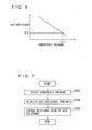
Fig. 6 shows the relationship between an atmospheric pressure and a permissible resistance value of a gate resistance. -
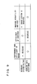
Fig. 7 is a flowchart of a control structure of a program executed in an HV-ECU that is a vehicle control device according to the second embodiment. -
Figs. 8A and 8B are timing charts showing a change in switching voltage between an emitter and a collector of a switching element. -
Fig. 9 shows the relationship between a change in voltage value and resistance value and the efficiency of a motor, the efficiency of an inverter and the cost. - A control device for a mobile unit according to embodiments of the present invention will be described hereinafter with reference to the drawings. In the following description, the same parts are represented by the same reference characters. The names and the functions are also the same. Therefore, the detailed description of those will not be repeated. It should be noted that, in the present invention, the mobile unit is not limited in particular, as long as the mobile unit has a motor mounted thereon. The mobile unit may be a hybrid vehicle, an electric vehicle or a fuel cell vehicle. In the present embodiments, the mobile unit is illustrated as a hybrid vehicle.
- As shown in
Fig. 1 , a vehicle on which a control device for a mobile unit according to the present embodiment is mounted has an HV-ECU (Hybrid Vehicle-Electronic Control Unit) 100, anengine ECU 200, a DC/DC converter 400, abattery 500, aninverter 600, and amotor 700 mounted thereon. It should be noted that the vehicle control device according to the present embodiment is implemented by a program executed in HV-ECU 100. -
Battery 500 is not limited in particular, as long asbattery 500 is a chargeable secondary battery.Battery 500 may be, for example, a nickel hydride battery or a lithium ion battery. - DC/
DC converter 400 boosts a DC voltage ofbattery 500. DC/DC converter 400 controls a boost voltage in response to a control signal received from HV-ECU 100. -
Inverter 600 converts the DC voltage boosted at DC/DC converter 400 to an AC voltage.Inverter 600 controls the AC voltage to be supplied tomotor 700, in response to a control signal received from HV-ECU 100. -
Motor 700 is an electric motor and is driven based on the AC voltage supplied frominverter 600.Motor 700 is, for example, a three-phase AC synchronous motor.Motor 700 is coupled to drive wheels (not shown) of the vehicle and causes the drive wheels to generate a driving force corresponding to the supplied AC voltage. -
Engine ECU 200 controls an output of an engine (not shown) based on various information (for example, an accelerator position, an amount of intake air and the like) detected by various sensors.Engine ECU 200 is connected to be capable of communicating with HV-ECU 100. Furthermore,engine ECU 200 has anatmospheric pressure sensor 300 connected thereto.Atmospheric pressure sensor 300 is a sensor that detects an atmospheric pressure around the vehicle.Atmospheric pressure sensor 300 transmits a detection signal corresponding to the detected atmospheric pressure toengine ECU 200. It should be noted that a well-known art may be used asatmospheric pressure sensor 300, and therefore, the detailed description thereof will not be given. - When the vehicle runs, partial discharge occurs at internal insulators in accordance with actuation of DC/
DC converter 400,inverter 600 andmotor 700. An amount of this partial discharge is increased or decreased corresponding to a change in atmospheric pressure. That is; as shown inFig. 2 , the relationship between an atmospheric pressure and an amount of partial discharge is such that the amount of partial discharge is likely to increase as the atmospheric pressure is decreased. Furthermore, the amount of partial discharge is likely to increase as a DC voltage supplied toinverter 600 rises. In particular, a region where the amount of partial discharge exceeds C(1) is a region where degradation in the insulation performance of the internal insulators is accelerated. That is, in the case where the vehicle runs under an environment where the atmospheric pressure is low, such as in a highland, the insulation performance of the insulators located within DC/DC converter 400,inverter 600 andmotor 700 can be degraded due to such an increase in amount of partial discharge. - Therefore, the present embodiment is characterized in that HV-
ECU 100 sets a voltage value that is to be supplied toinverter 600 andmotor 700, in accordance with the atmospheric pressure detected byatmospheric pressure sensor 300, and controls motor 700 based on the set voltage value. - Specifically, in HV-
ECU 100, a map created based on the relationship between an atmospheric pressure and an amount of partial discharge as shown inFig. 2 and showing the relationship between an atmospheric pressure and a permissible maximum voltage value as shown inFig. 3 is stored in memory and the like in advance. In HV-ECU 100, for example, a map showing the relationship between an atmospheric pressure and a voltage value within a range where an amount of partial discharge does not exceed C(1) at the atmospheric pressure is stored in memory and the like in advance. HV-ECU 100 sets a maximum voltage value corresponding to the atmospheric pressure detected byatmospheric pressure sensor 300 as a maximum value of the boost voltage output at DC/DC converter 400, that is, a system voltage value. Then, HV-ECU 100 transmits the control signal to DC/DC converter 400 to achieve the set system voltage value. - A control structure of a program executed in HV-
ECU 100 that is the vehicle control device according to the present embodiment will be described hereinafter with reference toFig. 4 . - In a step (steps are denoted as "S" hereinafter) 1000, HV-
ECU 100 detects an atmospheric pressure. HV-ECU 100 detects an atmospheric pressure based on the detection signal received fromatmospheric pressure sensor 300. - In an S1100, HV-
ECU 100 calculates a maximum voltage value from the detected atmospheric pressure and the map. In an S 1200, HV-ECU 100 sets the calculated maximum voltage value as a maximum value of the boost voltage and controls DC/DC converter 400. - An operation of HV-
ECU 100 that is the vehicle control device according to the present embodiment based on the above structure and flowchart will be described. - In the case where the vehicle runs in the highland such as a mountain area, an atmospheric pressure is detected (S1000), and a maximum value V(1) of the boost voltage corresponding to the detected atmospheric pressure P(1) is calculated based on the map as shown in
Fig. 3 (S1100). Since the detected atmospheric pressure is low in the highland, maximum value V(1) of the boost voltage is set to a value lower than a maximum value of the boost voltage at normal atmospheric pressure. - Calculated maximum value V(1) of the boost voltage is set and a voltage supplied from DC/
DC converter 400 toinverter 600 is controlled (S 1200). At this time, DC/DC converter 400 is controlled such that the voltage does not exceed set maximum value V(1) of the boost voltage. - As described above, in the control device for a mobile unit according to the present embodiment, the HV-ECU sets a voltage value that is to be supplied to the motor and the inverter, in accordance with the detected atmospheric pressure. The HV-ECU controls the motor based on the set voltage value. For example, the HV-ECU sets a voltage value that is to be supplied to the motor and the inverter such that the amount of partial discharge falls within a permissible range where acceleration of degradation in the insulation performance of the insulators can be suppressed at the detected atmospheric pressure. The voltage value at which the amount of partial discharge falls within the permissible range, that is, the voltage value lower than the voltage value at normal atmospheric pressure is set under the environment where the atmospheric pressure is relatively low, such as in the highland, so that an increase in amount of partial discharge can be suppressed. As a result, deterioration in the insulation performance of the insulators located within the motor and the inverter can be suppressed. Therefore, there can be provided a control device for a mobile unit in which the insulation performance is ensured in accordance with a change in atmospheric pressure.
- A control device for a mobile unit according to a second embodiment will be described hereinafter. A vehicle having the control device for a mobile unit according to the present embodiment mounted thereon is different from the vehicle having the control device for a mobile unit according to the above-described first embodiment mounted thereon in terms of a configuration of
inverter 600. The configuration of the vehicle having the control device for a mobile unit according to the present embodiment mounted thereon is otherwise the same as that of the vehicle having the control device for a mobile unit according to the above-described first embodiment mounted thereon. They are represented by the same reference characters. The functions are also the same. Therefore, the detailed description of those will not be repeated. - The present embodiment is characterized in that HV-
ECU 100 sets a control value related to control ofmotor 700 in accordance with the atmospheric pressure detected byatmospheric pressure sensor 300, and controls motor 700 based on the set control value. - Specifically, in the present embodiment,
inverter 600 includes aswitching element 1100 corresponding to respective phases ofmotor 700, and agate driving circuit 900. Ininverter 600, in response to the control signal from HV-ECU 100, opening and closing of switchingelement 1100 are controlled bygate driving circuit 900 corresponding to respective phases, and a DC voltage is converted to an AC voltage.Switching element 1100 is, for example, an IGBT (Insulated Gate Bipolar Transistor). - As shown in
Fig. 5 , ananti-parallel diode 1000 that causes a current to flow from the emitter side to the collector side is connected to switchingelement 1100. Agate resistance 800 is provided between the gate side of switchingelement 1100 andgate driving circuit 900. In response to the control signal from HV-ECU 100, a driving signal is output fromgate driving circuit 900 to switchingelement 1000, and switchingelement 1100 opens and closes in response to the driving signal. Opening and closing of switchingelement 1100 corresponding to respective phases are controlled, so that a DC voltage of DC/DC converter 600 is converted to an AC voltage and the converted AC voltage is supplied tomotor 700. - In the present embodiment,
gate resistance 800 is a variable resistor and a resistance value is variable in response to the control signal from HV-ECU 100. In the present embodiment, the control value is a resistance value ofgate resistance 800, and HV-ECU 100 sets a resistance value ofgate resistance 800 in accordance with the atmospheric pressure detected byatmospheric pressure sensor 300, and controlsgate resistance 800 to achieve the set resistance value. That is, in HV-ECU 100, a map created based on the relationship between an atmospheric pressure and an amount of partial discharge as shown inFig. 2 and showing the relationship between an atmospheric pressure and a permissible resistance value as shown inFig. 6 is stored in the memory and the like in advance. HV-ECU 100 sets a resistance value R(1) corresponding to atmospheric pressure P(1) detected byatmospheric pressure sensor 300. Then, HV-ECU 100 transmits the control signal togate resistance 800 to achieve set resistance value R(1). - A control structure of a program executed in HV-
ECU 100 that is the control device for a mobile unit according to the present embodiment will be described hereinafter with reference toFig. 7 . - In an S2000, HV-
ECU 100 detects an atmospheric pressure. HV-ECU 100 detects an atmospheric pressure based on the detection signal received fromatmospheric pressure sensor 300. - In an S2100, HV-
ECU 100 calculates a resistance value from the detected atmospheric pressure and the map. In an S2200, HV-ECU 100controls gate resistance 800 to achieve the calculated resistance value. - An operation of HV-
ECU 100 that is the vehicle control device according to the present embodiment based on the above structure and flowchart will be described. - In the case where the vehicle runs in the highland such as a mountain area, an atmospheric pressure is detected (S2000), and resistance value R(1) corresponding to detected atmospheric pressure P(1) is calculated based on the map as shown in
Fig. 6 (S2100). Since detected atmospheric pressure P(1) is low in the highland, resistance value R(1) is set to a value larger than a resistance value at normal atmospheric pressure. - The resistance value of
gate resistance 800 is controlled to be calculated resistance value R(1). At this time, as shown inFig. 8A , whengate resistance 800 is set to be small, a surge voltage is increased and a maximum value of the switching voltage between the emitter and the collector is increased. On the other hand, as shown inFig. 8B , whengate resistance 800 is set to be large, the surge voltage is decreased because of moderate rising of the switching voltage between the emitter and the collector. When the surge voltage is decreased, the maximum value of the switching voltage is reduced. Therefore, the amount of partial discharge generated atinverter 600 andmotor 700 is suppressed. - As described above, in the control device for a mobile unit according to the present embodiment, the HV-ECU sets a resistance value of the gate resistance provided between the switching element and the driving circuit in the inverter such that the amount of partial discharge falls within a permissible range at the detected atmospheric pressure. The HV-ECU controls the motor based on the set resistance value. The HV-ECU sets a resistance value such that the amount of partial discharge falls within the permissible range where acceleration of degradation in the insulation performance of the insulators can be suppressed. That is, under the environment where the atmospheric pressure is relatively low, such as in the highland, the resistance value larger than the resistance value of the gate resistance at normal atmospheric pressure is set such that the amount of partial discharge falls within the permissible range, so that an increase in amount of partial discharge can be suppressed. As a result, deterioration in the insulation performance of the insulators located within the motor and the inverter can be suppressed. Therefore, there can be provided a control device for a mobile unit in which the insulation performance is ensured in accordance with a change in atmospheric pressure.
- It is desirable that, depending on the condition of the motor, the HV-ECU preferably performs any one of control of the maximum value of the boost voltage in accordance with the atmospheric pressure that is described in the above first embodiment and control of the resistance value of the gate resistance in accordance with the atmospheric pressure that is described in the present embodiment.
- As shown in
Fig. 9 , the maximum value of the boost voltage is reduced by the control of the maximum value of the boost voltage in accordance with the atmospheric pressure that is described in the above first embodiment. Therefore, the performance and efficiency of the motor may be deteriorated, while deterioration in the efficiency of the inverter can be suppressed. Furthermore, the DC/DC converter is required to control the boost voltage. - On the other hand, the resistance value of the gate resistance is increased by the control of the resistance value of the gate resistance in accordance with the atmospheric pressure that is described in the present embodiment. Therefore, the efficiency of the inverter may be deteriorated, while deterioration in the performance and efficiency of the motor can be suppressed. Furthermore, a boost system such as the DC/DC converter is unnecessary to control the resistance value of the gate resistance.
- Therefore, in the case where the load required at the motor is low under the environment where the atmospheric pressure is low, the maximum value of the boost voltage is set to be low, so that deterioration in the efficiency of the inverter can be suppressed and the insulation performance can be ensured. On the other hand, in the case where the load required at the motor is high, the resistance value of the gate resistance in the inverter is set to be large, so that deterioration in the performance and efficiency of the motor can be suppressed and the insulation performance can be ensured. Therefore, any one of the voltage value and the resistance value is set in accordance with the load required at the motor, so that deterioration in the insulation performance can be suppressed and the motor can be controlled in accordance with the required load.
- It should be understood that the embodiments disclosed herein are illustrative and not limitative in any respect. The scope of the present invention is defined by the terms of the claims, rather than the description above, and is intended to include any modifications within the scope and meaning equivalent to the terms of the claims.
Claims (14)
- A control device for a mobile unit having a motor (700) mounted, electrical equipment (600) supplying electric power to said motor (700) being mounted on said mobile unit, the control device comprising:a detecting unit (300) detecting an atmospheric pressure; anda control unit (100) controlling said motor (700),said control unit (100)setting a voltage value that is to be supplied to said motor (700) and said electrical equipment (600), in accordance with said detected atmospheric pressure, andcontrolling said motor (700) based on said set voltage value.
- A control device for a mobile unit having a motor (700) mounted, comprising:a detecting unit (300) detecting an atmospheric pressure; anda control unit (100) controlling said motor (700),said control unit (100)setting a control value related to control of said motor (700) in accordance with said detected atmospheric pressure, andcontrolling said motor (700) based on said set control value.
- The control device for a mobile unit according to claim 2, wherein
an inverter (600) supplying electric power to said motor (700) is mounted on said mobile unit, and said inverter (600) includes a switching element (1100) and a driving circuit (900) opening and closing said switching element (1100), and
said control value is a resistance value of a gate resistance (800) provided between said switching element (1100) and said driving circuit (900). - The control device for a mobile unit according to claim 3, wherein
electrical equipment (600) supplying electric power to said motor (700) is mounted on said mobile unit, and
said control unit sets any one of a voltage value that is to be supplied to said motor (700) and said electrical equipment (600) and said resistance value, depending on a condition of said motor (700). - A control device for a mobile unit having a motor (700) mounted, electrical equipment (600) supplying electric power to said motor (700) being mounted on said mobile unit, the control device comprising:means for detecting an atmospheric pressure; andcontrol means (100) for controlling said motor (700),said control means (100) includingmeans for setting a voltage value that is to be supplied to said motor (700) and said electrical equipment (600), in accordance with said detected atmospheric pressure, andmeans for controlling said motor (700) based on said set voltage value.
- A control device for a mobile unit having a motor (700) mounted, comprising:means for detecting an atmospheric pressure; andcontrol means (100) for controlling said motor (700),said control means (100) includingsetting means for setting a control value related to control of said motor (700) in accordance with said detected atmospheric pressure, andmeans for controlling said motor (700) based on said set control value.
- The control device for a mobile unit according to claim 6, wherein
an inverter (600) supplying electric power to said motor (700) is mounted on said mobile unit, and said inverter (600) includes a switching element (1100) and a driving circuit (900) opening and closing said switching element (1100), and
said control value is a resistance value of a gate resistance (800) provided between said switching element (1100) and said driving circuit (900). - The control device for a mobile unit according to claim 7, wherein
electrical equipment (600) supplying electric power to said motor (700) is mounted on said mobile unit, and
said setting means includes means for setting any one of a voltage value that is to be supplied to said motor (700) and said electrical equipment (600) and said resistance value, depending on a condition of said motor (700). - A method for controlling a mobile unit having a motor (700) mounted, electrical equipment (600) supplying electric power to said motor (700) being mounted on said mobile unit, the method comprising the steps of:detecting an atmospheric pressure; andcontrolling said motor (700),said step of controlling said motor (700) including the steps of:setting a voltage value that is to be supplied to said motor (700) and said electrical equipment (600), in accordance with said detected atmospheric pressure; andcontrolling said motor (700) based on said set voltage value.
- A method for controlling a mobile unit having a motor (700) mounted, comprising the steps of:detecting an atmospheric pressure; andcontrolling said motor (700),said step of controlling said motor (700) including the steps of:setting a control value related to control of said motor (700) in accordance with said detected atmospheric pressure; andcontrolling said motor (700) based on said set control value.
- The method for controlling a mobile unit according to claim 10, wherein
an inverter (600) supplying electric power to said motor (700) is mounted on said mobile unit, and said inverter (600) includes a switching element (1100) and a driving circuit (900) opening and closing said switching element (1100), and
said control value is a resistance value of a gate resistance (800) provided between said switching element (1100) and said driving circuit (900). - The method for controlling a mobile unit according to claim 11, wherein
electrical equipment (600) supplying electric power to said motor (700) is mounted on said mobile unit, and
said step of setting a control value includes a step of setting any one of a voltage value that is to be supplied to said motor (700) and said electrical equipment (600) and said resistance value, depending on a condition of said motor (700). - A control device for a mobile unit having a motor (700) mounted, an inverter (600) supplying electric power to said motor (700) being mounted on said mobile unit, the control device comprising:an atmospheric pressure sensor (300) detecting an atmospheric pressure; andan electronic control unit (100) controlling said motor (700),said electronic control unit (100)setting a voltage value that is to be supplied to said motor (700) and said inverter (600), in accordance with said detected atmospheric pressure, andcontrolling said motor (700) based on said set voltage value.
- A control device for a mobile unit having a motor (700) mounted, comprising:an atmospheric pressure sensor (300) detecting an atmospheric pressure; andan electronic control unit (100) controlling said motor (700),said electronic control unit (100)setting a control value related to control of said motor (700) in accordance with said detected atmospheric pressure, andcontrolling said motor (700) based on said set control value.
Applications Claiming Priority (1)
| Application Number | Priority Date | Filing Date | Title |
|---|---|---|---|
| PCT/JP2006/318327 WO2008029489A1 (en) | 2006-09-08 | 2006-09-08 | Mobile body control device |
Publications (3)
| Publication Number | Publication Date |
|---|---|
| EP2060433A1 true EP2060433A1 (en) | 2009-05-20 |
| EP2060433A4 EP2060433A4 (en) | 2017-03-22 |
| EP2060433B1 EP2060433B1 (en) | 2019-12-25 |
Family
ID=39156935
Family Applications (1)
| Application Number | Title | Priority Date | Filing Date |
|---|---|---|---|
| EP06821804.9A Active EP2060433B1 (en) | 2006-09-08 | 2006-09-08 | Mobile body control device |
Country Status (5)
| Country | Link |
|---|---|
| US (1) | US8311691B2 (en) |
| EP (1) | EP2060433B1 (en) |
| CN (1) | CN101511629B (en) |
| BR (1) | BRPI0622001B1 (en) |
| WO (1) | WO2008029489A1 (en) |
Cited By (1)
| Publication number | Priority date | Publication date | Assignee | Title |
|---|---|---|---|---|
| WO2009115875A1 (en) * | 2008-03-21 | 2009-09-24 | Toyota Jidosha Kabushiki Kaisha | Hybrid vehicle, and hybrid-vehicle control method |
Families Citing this family (7)
| Publication number | Priority date | Publication date | Assignee | Title |
|---|---|---|---|---|
| JP5433392B2 (en) * | 2009-12-16 | 2014-03-05 | 日立オートモティブシステムズ株式会社 | Rotating electric machine for electric vehicle, drive control device, and insulation diagnosis method |
| JP2015065742A (en) * | 2013-09-24 | 2015-04-09 | トヨタ自動車株式会社 | Inverter controller and control method for inverter device |
| JP5949749B2 (en) * | 2013-12-24 | 2016-07-13 | トヨタ自動車株式会社 | Vehicle power supply |
| EP3470858B1 (en) * | 2017-10-16 | 2022-10-05 | Hamilton Sundstrand Corporation | Motor drive assembly |
| US10576839B2 (en) * | 2018-08-01 | 2020-03-03 | Toyota Motor Engineering & Manufacturing North America, Inc. | Motor lock overheat mitigation control for autonomous vehicles |
| GB202008070D0 (en) * | 2020-05-29 | 2020-07-15 | Rolls Royce Plc | Aircraft electrical power distribution |
| US11649065B2 (en) * | 2021-08-13 | 2023-05-16 | Pratt & Whitney Canada Corp. | DC bus voltage control |
Family Cites Families (16)
| Publication number | Priority date | Publication date | Assignee | Title |
|---|---|---|---|---|
| JP3768296B2 (en) * | 1996-08-05 | 2006-04-19 | 三菱自動車工業株式会社 | In-cylinder injection type spark ignition internal combustion engine control device |
| JP3211699B2 (en) * | 1996-09-17 | 2001-09-25 | トヨタ自動車株式会社 | Power output device |
| JP2000088091A (en) | 1998-09-17 | 2000-03-28 | Mazda Motor Corp | Control device for automatic transmission |
| JP3352987B2 (en) * | 1999-12-20 | 2002-12-03 | 本田技研工業株式会社 | Control device for hybrid vehicle |
| EP1197494A3 (en) * | 2000-09-21 | 2004-05-26 | Kanto Kagaku Kabushiki Kaisha | New organic borate compounds and the nonaqueous electrolytes and lithium secondary batteries using the compounds |
| US6859708B2 (en) * | 2000-11-22 | 2005-02-22 | Honda Giken Kogyo Kabushiki Kaisha | Vehicle control system |
| JP4672183B2 (en) | 2001-05-23 | 2011-04-20 | 本田技研工業株式会社 | Fuel cell control device and fuel cell vehicle control device |
| JP3867270B2 (en) * | 2002-06-28 | 2007-01-10 | 株式会社日立製作所 | Electric vehicle control device |
| US6775601B2 (en) * | 2002-08-06 | 2004-08-10 | Delphi Technologies, Inc. | Method and control system for controlling propulsion in a hybrid vehicle |
| JP3931765B2 (en) * | 2002-08-28 | 2007-06-20 | トヨタ自動車株式会社 | Engine control device and method, hybrid power output device, and hybrid vehicle |
| JP2004208409A (en) | 2002-12-25 | 2004-07-22 | Denso Corp | Power control device for vehicle |
| EP1493604B1 (en) * | 2003-07-04 | 2013-09-18 | Honda Motor Co., Ltd. | Control apparatus for hybrid vehicle |
| CN1787929A (en) * | 2003-09-16 | 2006-06-14 | 爱信艾达株式会社 | Controller for motor driving vehicle |
| JP4258467B2 (en) | 2004-12-27 | 2009-04-30 | 日産自動車株式会社 | Hybrid vehicle driving force control device |
| JP4583998B2 (en) | 2005-04-04 | 2010-11-17 | トヨタ自動車株式会社 | Control device for moving body |
| JP4639916B2 (en) | 2005-04-05 | 2011-02-23 | トヨタ自動車株式会社 | Control device for moving body |
-
2006
- 2006-09-08 CN CN2006800557786A patent/CN101511629B/en active Active
- 2006-09-08 EP EP06821804.9A patent/EP2060433B1/en active Active
- 2006-09-08 BR BRPI0622001-0A patent/BRPI0622001B1/en active IP Right Grant
- 2006-09-08 WO PCT/JP2006/318327 patent/WO2008029489A1/en not_active Ceased
- 2006-09-08 US US12/310,280 patent/US8311691B2/en active Active
Non-Patent Citations (1)
| Title |
|---|
| See references of WO2008029489A1 * |
Cited By (2)
| Publication number | Priority date | Publication date | Assignee | Title |
|---|---|---|---|---|
| WO2009115875A1 (en) * | 2008-03-21 | 2009-09-24 | Toyota Jidosha Kabushiki Kaisha | Hybrid vehicle, and hybrid-vehicle control method |
| US8146692B2 (en) | 2008-03-21 | 2012-04-03 | Toyota Jidosha Kabushiki Kaisha | Hybrid vehicle, and hybrid-vehicle control method |
Also Published As
| Publication number | Publication date |
|---|---|
| EP2060433B1 (en) | 2019-12-25 |
| EP2060433A4 (en) | 2017-03-22 |
| WO2008029489A1 (en) | 2008-03-13 |
| CN101511629A (en) | 2009-08-19 |
| CN101511629B (en) | 2012-10-17 |
| BRPI0622001A2 (en) | 2015-08-04 |
| US8311691B2 (en) | 2012-11-13 |
| US20090198397A1 (en) | 2009-08-06 |
| BRPI0622001B1 (en) | 2018-08-14 |
Similar Documents
| Publication | Publication Date | Title |
|---|---|---|
| JP4639916B2 (en) | Control device for moving body | |
| US6630810B2 (en) | Hybrid vehicle and control method therefor | |
| US8027181B2 (en) | Load drive device and vehicle equipped with the same | |
| US7834578B2 (en) | Load driving apparatus, vehicle, and abnormality processing method at load driving apparatus | |
| US10081251B2 (en) | Apparatus for controlling power converters | |
| US8673514B2 (en) | Fuel cell system and boost converter for fuel cell | |
| KR101143438B1 (en) | Vehicle power control device | |
| KR101171908B1 (en) | System of dc link pre-recharge for plug-in hybrid vehicle | |
| US8546973B2 (en) | Mild hybrid system and method for controlling the same | |
| US20200295660A1 (en) | Power system | |
| EP1844971A1 (en) | Electric load control device | |
| US8502411B2 (en) | Power limiting apparatus for electric system, power limiting method for electric system and electric system | |
| CN107342619A (en) | Vehicle power source device | |
| US9793749B2 (en) | Vehicle charging apparatus | |
| US8413439B2 (en) | Power supply for onboard equipment of an automobile | |
| JP4926227B2 (en) | Power supply | |
| US8311691B2 (en) | Control device for mobile unit | |
| CN103358886A (en) | Cooling fan control device | |
| US20210376639A1 (en) | System for output ratio configuration of start-up battery and rapid energy storage module in parallel | |
| JP2006087163A (en) | Vehicle power generation control device | |
| JP2008035670A (en) | VEHICLE POWER SUPPLY DEVICE, CONTROL METHOD FOR POWER SUPPLY DEVICE, PROGRAM FOR IMPLEMENTING THE CONTROL METHOD, AND RECORDING MEDIUM CONTAINING THE PROGRAM | |
| JP2006115643A (en) | Control device for load drive circuit | |
| KR101028022B1 (en) | Boosting system and control method for motor control of hybrid vehicle | |
| JP4501604B2 (en) | Electrical system control equipment |
Legal Events
| Date | Code | Title | Description |
|---|---|---|---|
| PUAI | Public reference made under article 153(3) epc to a published international application that has entered the european phase |
Free format text: ORIGINAL CODE: 0009012 |
|
| 17P | Request for examination filed |
Effective date: 20090303 |
|
| AK | Designated contracting states |
Kind code of ref document: A1 Designated state(s): AT BE BG CH CY CZ DE DK EE ES FI FR GB GR HU IE IS IT LI LT LU LV MC NL PL PT RO SE SI SK TR |
|
| AX | Request for extension of the european patent |
Extension state: AL BA HR MK RS |
|
| RBV | Designated contracting states (corrected) |
Designated state(s): DE FR |
|
| DAX | Request for extension of the european patent (deleted) | ||
| RAP1 | Party data changed (applicant data changed or rights of an application transferred) |
Owner name: TOYOTA JIDOSHA KABUSHIKI KAISHA |
|
| RA4 | Supplementary search report drawn up and despatched (corrected) |
Effective date: 20170217 |
|
| RIC1 | Information provided on ipc code assigned before grant |
Ipc: B60L 15/20 20060101ALI20170213BHEP Ipc: B60L 11/02 20060101ALI20170213BHEP Ipc: H02P 29/032 20160101ALI20170213BHEP Ipc: B60L 9/18 20060101AFI20170213BHEP Ipc: B60W 10/08 20060101ALI20170213BHEP Ipc: B60W 20/00 20160101ALI20170213BHEP Ipc: B60L 11/18 20060101ALI20170213BHEP Ipc: B60L 3/00 20060101ALI20170213BHEP |
|
| RIC1 | Information provided on ipc code assigned before grant |
Ipc: B60L 11/02 20060101ALI20170925BHEP Ipc: B60W 10/08 20060101ALI20170925BHEP Ipc: B60W 20/10 20160101ALI20170925BHEP Ipc: H02P 29/032 20160101ALI20170925BHEP Ipc: B60W 10/24 20060101ALI20170925BHEP Ipc: B60L 3/00 20060101ALI20170925BHEP Ipc: B60L 9/18 20060101AFI20170925BHEP Ipc: B60W 20/00 20160101ALI20170925BHEP Ipc: B60L 11/18 20060101ALI20170925BHEP Ipc: B60L 15/20 20060101ALI20170925BHEP |
|
| 17Q | First examination report despatched |
Effective date: 20180613 |
|
| REG | Reference to a national code |
Ref country code: DE Ref legal event code: R079 Ref document number: 602006058991 Country of ref document: DE Free format text: PREVIOUS MAIN CLASS: B60L0009180000 Ipc: B60L0050500000 |
|
| RIC1 | Information provided on ipc code assigned before grant |
Ipc: H02P 29/032 20160101ALI20190527BHEP Ipc: B60W 10/24 20060101ALI20190527BHEP Ipc: B60L 50/50 20190101AFI20190527BHEP Ipc: B60L 15/20 20060101ALI20190527BHEP Ipc: B60W 20/00 20160101ALI20190527BHEP Ipc: B60L 3/00 20190101ALI20190527BHEP Ipc: B60L 9/18 20060101ALI20190527BHEP Ipc: B60W 10/08 20060101ALI20190527BHEP Ipc: B60W 20/10 20160101ALI20190527BHEP |
|
| GRAP | Despatch of communication of intention to grant a patent |
Free format text: ORIGINAL CODE: EPIDOSNIGR1 |
|
| INTG | Intention to grant announced |
Effective date: 20190710 |
|
| GRAS | Grant fee paid |
Free format text: ORIGINAL CODE: EPIDOSNIGR3 |
|
| GRAA | (expected) grant |
Free format text: ORIGINAL CODE: 0009210 |
|
| AK | Designated contracting states |
Kind code of ref document: B1 Designated state(s): DE FR |
|
| REG | Reference to a national code |
Ref country code: DE Ref legal event code: R096 Ref document number: 602006058991 Country of ref document: DE |
|
| REG | Reference to a national code |
Ref country code: DE Ref legal event code: R097 Ref document number: 602006058991 Country of ref document: DE |
|
| PLBE | No opposition filed within time limit |
Free format text: ORIGINAL CODE: 0009261 |
|
| STAA | Information on the status of an ep patent application or granted ep patent |
Free format text: STATUS: NO OPPOSITION FILED WITHIN TIME LIMIT |
|
| 26N | No opposition filed |
Effective date: 20200928 |
|
| PG25 | Lapsed in a contracting state [announced via postgrant information from national office to epo] |
Ref country code: FR Free format text: LAPSE BECAUSE OF NON-PAYMENT OF DUE FEES Effective date: 20200930 |
|
| REG | Reference to a national code |
Ref country code: DE Ref legal event code: R084 Ref document number: 602006058991 Country of ref document: DE |
|
| P01 | Opt-out of the competence of the unified patent court (upc) registered |
Effective date: 20230427 |
|
| PGFP | Annual fee paid to national office [announced via postgrant information from national office to epo] |
Ref country code: DE Payment date: 20250730 Year of fee payment: 20 |