EP2060432A1 - On-board instrument indicator device - Google Patents
On-board instrument indicator device Download PDFInfo
- Publication number
- EP2060432A1 EP2060432A1 EP07425723A EP07425723A EP2060432A1 EP 2060432 A1 EP2060432 A1 EP 2060432A1 EP 07425723 A EP07425723 A EP 07425723A EP 07425723 A EP07425723 A EP 07425723A EP 2060432 A1 EP2060432 A1 EP 2060432A1
- Authority
- EP
- European Patent Office
- Prior art keywords
- hand
- slot
- lid
- axis
- prisms
- Prior art date
- Legal status (The legal status is an assumption and is not a legal conclusion. Google has not performed a legal analysis and makes no representation as to the accuracy of the status listed.)
- Granted
Links
Images


Classifications
-
- G—PHYSICS
- G01—MEASURING; TESTING
- G01D—MEASURING NOT SPECIALLY ADAPTED FOR A SPECIFIC VARIABLE; ARRANGEMENTS FOR MEASURING TWO OR MORE VARIABLES NOT COVERED IN A SINGLE OTHER SUBCLASS; TARIFF METERING APPARATUS; MEASURING OR TESTING NOT OTHERWISE PROVIDED FOR
- G01D13/00—Component parts of indicators for measuring arrangements not specially adapted for a specific variable
- G01D13/22—Pointers, e.g. settable pointer
- G01D13/26—Pointers, e.g. settable pointer adapted to perform a further operation, e.g. making electrical contact
- G01D13/265—Pointers which conduct light
-
- B—PERFORMING OPERATIONS; TRANSPORTING
- B60—VEHICLES IN GENERAL
- B60K—ARRANGEMENT OR MOUNTING OF PROPULSION UNITS OR OF TRANSMISSIONS IN VEHICLES; ARRANGEMENT OR MOUNTING OF PLURAL DIVERSE PRIME-MOVERS IN VEHICLES; AUXILIARY DRIVES FOR VEHICLES; INSTRUMENTATION OR DASHBOARDS FOR VEHICLES; ARRANGEMENTS IN CONNECTION WITH COOLING, AIR INTAKE, GAS EXHAUST OR FUEL SUPPLY OF PROPULSION UNITS IN VEHICLES
- B60K2360/00—Indexing scheme associated with groups B60K35/00 or B60K37/00 relating to details of instruments or dashboards
- B60K2360/60—Structural details of dashboards or instruments
- B60K2360/68—Features of instruments
- B60K2360/698—Pointers of combined instruments
- B60K2360/6992—Light conducting pointers
Definitions
- the present invention relates to an on-board instrument indicator device.
- the present invention relates to an indicator device of the type comprising a hand having a determined thickness and a pin supporting the hand and turnable about an axis; the hand being provided with reflecting prisms for directing a differently oriented light beam along the hand; and a cup-shaped lid for covering the prisms; the lid having a side wall and a bottom wall and being provided with a slot engaged by a portion of the hand carrying said prisms.
- an indicator device as claimed in claim 1 and preferably in any one of the claims either directly or indirectly depending on claim 1 is provided.
- numeral 1 indicates as a whole an on-board instrument comprising an indicator device 2, which comprises a pointer 3 and a lid 4, as shown in figures 2, 3 , 6 and 10 .
- the pointer 3 comprises in turn a hand 5 and a pin 6, which supports the hand 5 and is mounted through a panel A of the instrument 1 to rotate, with respect to the panel A and under the control of an instrument (not shown), about a rotation axis 7 transversal to the panel A and to the hand 5.
- the hand 5 is in the form of a flat plate laterally delimited by two essentially rectilinear edges, indicated by numerals 8 and 9 respectively, which are perpendicular to the rotation axis 7 which identifies, on the hand 5, two portions 10 and 11 arranged on opposite sides of the rotation axis 7 itself, the portion 10 defining the hand itself, while the portion 11 being a shorter portion.
- the hand 5 is provided with reflecting prisms 12, in this case two reflecting prisms 12, which direct a differently oriented light beam (not shown) along the hand 5.
- this light beam is output by the mentioned instrument (not shown) along the axis 7 and is conveyed onto the prisms 12 by the pin 6 which, for this purpose, is normally formed by transparent material.
- each prism 12 has a reflecting surface 13 which deviates the light beam by 90° with respect to its original orientation.
- the prisms 12 are arranged on opposite sides of the rotation axis 7 and delimit an essentially triangular cavity 14 made in the hand 5 astride the rotation axis 7.
- the hand 5 is provided with a centring device 15, which cooperates with the lid 4 to hold the lid 4 itself in a position coaxial to the rotation axis 7, and with a resting device 16 cooperating with the lid 4 to support the lid 4 itself on the pointer 3 in the mentioned position coaxial to the rotation axis 7.
- the centring device 15 comprises two appendixes 17 and 18, which extend from the edge 9 of the hand 5 in a direction essentially parallel to the rotation axis 7 and are arranged in specular positions with respect to the rotation axis 7 itself and at a predetermined distance from each other.
- the appendix 18 extends from portion 11, is arranged near the free end of the portion 11 and identifies thereon an end segment 19 arranged outside the appendix 18 and joined to the appendix 18 by means of a shoulder 20.
- the resting device 16 comprises two pairs of wings or shelves 21, wherein the wings 21 of each pair are symmetrically arranged with respect to the rotation axis 7, extend from a corresponding side surface of the hand 5 in a direction transversal to the rotation axis 7, are arranged at a determined distance from the edge 8, equal for all wings 21, and each presents a corresponding notch 22 parallel to the edge 8.
- the lid 4 which is formed by an elastically deformable material, is cup-shaped, comprises an essentially flat bottom wall 23 and has a thickness essentially equal to the distance existing between each wing 21 and the edge 8, and an essentially cylindrical side wall 24, which has an internal diameter rounding up the distance existing between the external surfaces of the appendixes 17 and 18, and a thickness essentially equal to the length of the shoulder 20.
- a diametric slot 25 is obtained, which has a width rounding up the thickness of the hand 5, measured transversally to the rotation axis 7, and comprises a central portion 26, which is obtained through the bottom wall 23, and two side portions, indicated by numerals 27 and 28 respectively, which are obtained in the side wall 24, are respectively engaged by the portion 10 and by the portion 11 of the hand 5 and have corresponding length essentially equal to the distance existing between the edges 8 and 9.
- the two side portions 27 and 28 have two corresponding ends, indicated by numerals 29 and 30, and communicate with corresponding ends of the central portion 26.
- An internal surface 31 of the bottom wall 23 of the lid 4 is provided with two ribs 32 protruding inwards from the bottom wall 23 itself, arranged on opposite sides of the central portion 26 of the slot 25 and engaged inside the notches 22 of corresponding pairs of wings 21.
- the hand 5 is inserted into the lid 4 through the slot 25 and rotated to reach a position in which the portion 10 of the hand 5 rests on the end 29 of the side portion 27 and the appendix 17 defines a side contrast for an internal surface 33 of the side wall 24 of the lid 4. In this position, the side portion 27 is engaged by the portion 10 of the hand 5.
- the hand 5 is further rotated so as to make the wings 21 cooperate with the ribs 32 of the lid 4.
- each rib 32 engages the notches 22 of two wings 21;
- the hand 5 engages the central portion 26 of the slot 25;
- the lid 4 is arranged on the hand 5 in a position transversal to the rotation axis 7;
- the appendix 18 is arranged in contact with the internal surface 33 of the side wall 24; and the end segment 19 of the portion 11 is snappingly engaged into the side portion 28.
- the hand 5 engages, at this point, all the portions of the slot 25 and the lid 4 is locked on the hand 5 in a position coaxial to the rotation axis 7.
- the lid 4 is formed by an elastically deformable material, so that by applying a pressure to the side wall 24, it is possible to release the portion 28 of the slot 25 from the portion 11 of the hand 5 and pull out the hand 5 itself through the slot 25.
- the embodiment of the on-board instrument 1 shown in figures 10 and 11 differs from that shown in figures from 1 to 9 in that the pointer 3 in figures 10 and 11 comprises a centring device 15, which comprises, in turn, two appendixes 34 and two appendixes 35, wherein the two appendixes 35 are arranged reciprocally opposed and aligned on opposite sides of the hand 5 and extend from corresponding side surfaces of the hand 5, at the edge 9, in a direction transversal to the rotation axis 7 and specifically extend from the portion 11, are arranged near the free end of the portion 11 and identify on the same an end segment 19 arranged outside the appendixes 35 and joined to the appendixes 35 by means of a shoulder 20.
- a centring device 15 comprises, in turn, two appendixes 34 and two appendixes 35, wherein the two appendixes 35 are arranged reciprocally opposed and aligned on opposite sides of the hand 5 and extend from corresponding side surfaces of the hand 5, at the edge 9, in a direction transvers
- the appendixes 34 instead extend from corresponding reflecting surfaces 13 of the prisms 12, at the edge 9 of the hand 5 in a direction transversal to the rotation axis 7.
- the distance between the external surfaces of the appendixes 34 and the appendixes 35 rounds down the internal diameter of the side wall 24 of the lid 4.
- the hand 5 is inserted into the lid 4 through the slot 25 and rotated to reach a position in which the portion 10 of the hand 5 rests on the end 29 of the side portion 27 and the appendixes 34 define a side contrast for the internal surface 33 of the side wall 24 of the lid 4.
- the appendixes 35 are arranged in contact with the internal surface 33 of the side wall 24 defining a contrast for the side wall 24 itself and the end segment 19 of the portion 11 is snappingly engaged into the side portion 28; in this manner, the external structure of the on-board instrument 1 and the assembly method of the indicator device 2 remain unchanged.
Landscapes
- Physics & Mathematics (AREA)
- General Physics & Mathematics (AREA)
- Details Of Measuring And Other Instruments (AREA)
- Details Of Measuring Devices (AREA)
- Freezers Or Refrigerated Showcases (AREA)
- Push-Button Switches (AREA)
- Instrument Panels (AREA)
Abstract
Description
- The present invention relates to an on-board instrument indicator device.
- Specifically, the present invention relates to an indicator device of the type comprising a hand having a determined thickness and a pin supporting the hand and turnable about an axis; the hand being provided with reflecting prisms for directing a differently oriented light beam along the hand; and a cup-shaped lid for covering the prisms; the lid having a side wall and a bottom wall and being provided with a slot engaged by a portion of the hand carrying said prisms.
- In the known indicator devices of the above-described type, the connection of the lid to the hand normally requires the use of separate assembly elements, which make the structure of the indicator device relatively complex and which complicate the assembly procedures thereof.
- It is the object of the present invention to provide an indicator device of the above-described type, which is simple and cost-effective to make and which is free from the above-mentioned drawbacks.
- According to the present invention, an indicator device as claimed in claim 1 and preferably in any one of the claims either directly or indirectly depending on claim 1 is provided.
- The present invention will now be described with reference to the accompanying drawings, which illustrate some non-limitative embodiments thereof, in which:
-
figure 1 is a diagrammatic view of an on-board instrument provided with a preferred embodiment of the indicator device according to the present invention; -
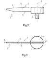
figure 2 shows a side elevation view on enlarged scale of the indicator device infigure 1 ; -
figure 3 is a plan view of the indicator device infigure 2 ; -
figure 4 is a first end view of the indicator device infigures 2 and 3 ; -
figure 5 is a perspective bottom view of a detail in figures from 2 to 4; -
figure 6 is a section taken along the line VI-VI infigure 3 ; -
figure 7 is a second end view, with sectional parts, of the indicator device infigures 2 and 3 ; -
figure 8 shows a detail offigure 6 on enlarged scale; -
figure 9 shows a detail offigure 7 on enlarged scale; and -
figures 10 and 11 relate to a further embodiment of the indicator device according to the present invention. - In
figure 1 , numeral 1 indicates as a whole an on-board instrument comprising anindicator device 2, which comprises apointer 3 and alid 4, as shown infigures 2, 3 ,6 and10 . - The
pointer 3 comprises in turn ahand 5 and apin 6, which supports thehand 5 and is mounted through a panel A of the instrument 1 to rotate, with respect to the panel A and under the control of an instrument (not shown), about arotation axis 7 transversal to the panel A and to thehand 5. - As shown in figures from 6 to 9, the
hand 5 is in the form of a flat plate laterally delimited by two essentially rectilinear edges, indicated bynumerals 8 and 9 respectively, which are perpendicular to therotation axis 7 which identifies, on thehand 5, twoportions rotation axis 7 itself, theportion 10 defining the hand itself, while theportion 11 being a shorter portion. - The
hand 5 is provided with reflectingprisms 12, in this case two reflectingprisms 12, which direct a differently oriented light beam (not shown) along thehand 5. In general, this light beam is output by the mentioned instrument (not shown) along theaxis 7 and is conveyed onto theprisms 12 by thepin 6 which, for this purpose, is normally formed by transparent material. In the example shown, eachprism 12 has a reflectingsurface 13 which deviates the light beam by 90° with respect to its original orientation. Theprisms 12 are arranged on opposite sides of therotation axis 7 and delimit an essentiallytriangular cavity 14 made in thehand 5 astride therotation axis 7. - The
hand 5 is provided with acentring device 15, which cooperates with thelid 4 to hold thelid 4 itself in a position coaxial to therotation axis 7, and with aresting device 16 cooperating with thelid 4 to support thelid 4 itself on thepointer 3 in the mentioned position coaxial to therotation axis 7. - As shown better in detail in
figure 6 , thecentring device 15 comprises twoappendixes edge 9 of thehand 5 in a direction essentially parallel to therotation axis 7 and are arranged in specular positions with respect to therotation axis 7 itself and at a predetermined distance from each other. Specifically, theappendix 18 extends fromportion 11, is arranged near the free end of theportion 11 and identifies thereon anend segment 19 arranged outside theappendix 18 and joined to theappendix 18 by means of ashoulder 20. - As shown better in detail in
figure 6 , theresting device 16 comprises two pairs of wings orshelves 21, wherein thewings 21 of each pair are symmetrically arranged with respect to therotation axis 7, extend from a corresponding side surface of thehand 5 in a direction transversal to therotation axis 7, are arranged at a determined distance from the edge 8, equal for allwings 21, and each presents acorresponding notch 22 parallel to the edge 8. - As shown in figures from 2 to 5, the
lid 4, which is formed by an elastically deformable material, is cup-shaped, comprises an essentiallyflat bottom wall 23 and has a thickness essentially equal to the distance existing between eachwing 21 and the edge 8, and an essentiallycylindrical side wall 24, which has an internal diameter rounding up the distance existing between the external surfaces of theappendixes shoulder 20. - Through the lid 4 a
diametric slot 25 is obtained, which has a width rounding up the thickness of thehand 5, measured transversally to therotation axis 7, and comprises acentral portion 26, which is obtained through thebottom wall 23, and two side portions, indicated bynumerals side wall 24, are respectively engaged by theportion 10 and by theportion 11 of thehand 5 and have corresponding length essentially equal to the distance existing between theedges 8 and 9. The twoside portions numerals central portion 26. Aninternal surface 31 of thebottom wall 23 of thelid 4 is provided with tworibs 32 protruding inwards from thebottom wall 23 itself, arranged on opposite sides of thecentral portion 26 of theslot 25 and engaged inside thenotches 22 of corresponding pairs ofwings 21. - In use, during the assembly of the
indicator device 2, thehand 5 is inserted into thelid 4 through theslot 25 and rotated to reach a position in which theportion 10 of thehand 5 rests on theend 29 of theside portion 27 and theappendix 17 defines a side contrast for aninternal surface 33 of theside wall 24 of thelid 4. In this position, theside portion 27 is engaged by theportion 10 of thehand 5. - The
hand 5 is further rotated so as to make thewings 21 cooperate with theribs 32 of thelid 4. Specifically, when thewings 21 are arranged in contact with theinternal surface 31 of thebottom wall 23, eachrib 32 engages thenotches 22 of twowings 21; thehand 5 engages thecentral portion 26 of theslot 25; thelid 4 is arranged on thehand 5 in a position transversal to therotation axis 7; theappendix 18 is arranged in contact with theinternal surface 33 of theside wall 24; and theend segment 19 of theportion 11 is snappingly engaged into theside portion 28. Thehand 5 engages, at this point, all the portions of theslot 25 and thelid 4 is locked on thehand 5 in a position coaxial to therotation axis 7. - The
lid 4 is formed by an elastically deformable material, so that by applying a pressure to theside wall 24, it is possible to release theportion 28 of theslot 25 from theportion 11 of thehand 5 and pull out thehand 5 itself through theslot 25. - The embodiment of the on-board instrument 1 shown in
figures 10 and 11 is similar to that shown in figures from 1 to 9, and the corresponding parts of the two embodiments are marked with the same reference numbers, where possible. - The embodiment of the on-board instrument 1 shown in
figures 10 and 11 differs from that shown in figures from 1 to 9 in that thepointer 3 infigures 10 and 11 comprises acentring device 15, which comprises, in turn, twoappendixes 34 and twoappendixes 35, wherein the twoappendixes 35 are arranged reciprocally opposed and aligned on opposite sides of thehand 5 and extend from corresponding side surfaces of thehand 5, at theedge 9, in a direction transversal to therotation axis 7 and specifically extend from theportion 11, are arranged near the free end of theportion 11 and identify on the same anend segment 19 arranged outside theappendixes 35 and joined to theappendixes 35 by means of ashoulder 20. Theappendixes 34 instead extend from correspondingreflecting surfaces 13 of theprisms 12, at theedge 9 of thehand 5 in a direction transversal to therotation axis 7. The distance between the external surfaces of theappendixes 34 and theappendixes 35 rounds down the internal diameter of theside wall 24 of thelid 4. - In use, during the assembly of the
indicator device 2, thehand 5 is inserted into thelid 4 through theslot 25 and rotated to reach a position in which theportion 10 of thehand 5 rests on theend 29 of theside portion 27 and theappendixes 34 define a side contrast for theinternal surface 33 of theside wall 24 of thelid 4. Subsequently, theappendixes 35 are arranged in contact with theinternal surface 33 of theside wall 24 defining a contrast for theside wall 24 itself and theend segment 19 of theportion 11 is snappingly engaged into theside portion 28; in this manner, the external structure of the on-board instrument 1 and the assembly method of theindicator device 2 remain unchanged.
Claims (12)
- An on-board instrument indicator device (1), the indicator device (2) comprising:a pointer (3) in turn comprising a hand (5) having a determined thickness and a pin (6) supporting the hand (5) and turnable about an axis (7); the hand (5) being provided with reflecting prisms (12) for directing a differently oriented light beam along the hand (5); anda cup-shaped lid (4) for covering the prisms (12); the lid (4) having a side wall (24) and a bottom wall (23) and being provided with a slot (25) engaged by a portion of the hand (5) carrying said prisms (12);the indicator device (2) being characterised in that the slot (25) comprises a central portion (26) obtained through the bottom wall (23), and a first and a second side portions (27, 28) obtained in the side wall (24) and communicating with corresponding ends of the central portion (26); the first side portion (27) having an end (29) serving as a rest for the hand (5); and the hand (5) being snappingly coupled to the second side portion (28) to lock the lid (4) on the hand (5) in a position coaxial to said axis (7).
- A device according to claim 1, wherein the lid (4) is formed by an elastically deformable material.
- A device according to claim 1 or 2, wherein the slot (25) has a width rounding up the thickness of the hand (5); the hand (5) having side wings (21) adapted to cooperate with an internal surface (31) of the bottom wall (23) to position the hand (5) itself in a position transversal to the said axis (7) and engaging with the slot (25).
- A device according to claim 3, wherein the bottom wall (23) is provided with two ribs (32) protruding inward from the bottom wall (23) itself ad arranged on opposite sides of the central portion (26) of the slot (25); each said side wing (21) having a slot (22) engaged by a corresponding said rib (32).
- A device according to any one of the preceding claims, wherein the hand (5) comprises a first and a second portions (10, 11) arranged on opposite sides of said axis (7) and engaging the first side portion (27) and the second side portion (28) of the slot (25), respectively; the second portion (11) of the hand (5) snappingly engaging the second side portion (28) of the slot (25).
- A device according to claim 5, wherein the hand (5) has, on the side facing the pin (6), centring means (17, 18, 34, 35) cooperating with an internal surface (33) of the side wall (24) of the lid (4) to fix the lid (4) itself in a position coaxial to said axis (7); the second portion (11) of the hand (5) having an end segment (19) protruding outwards from the centring means (17, 18, 34, 35) and snappingly engaged into said second side portion (28).
- A device according to claim 6, wherein said end segment (19) has a length essentially equal to a thickness of the side wall (24) of the lid (4).
- A device according to claim 6 or 7, wherein the centring means (17, 18) comprise two appendixes (17, 18) protruding from the hand (5) towards the pin (6) and arranged in specular positions with respect to said axis (7).
- A device according to claim 6 or 7, wherein the centring means (34, 35) comprise two pairs of appendixes (34, 35) protruding from the hand (5) in a direction transversal to the rotation axis (7) and arranged in specular positions with respect to said axis (7).
- A device according to any one of the preceding claims, wherein the hand (5) is shaped as a flat plate having said thickness and laterally delimited by a first and a second essentially rectilinear edges (8, 9), which are perpendicular to said axis (7), and are arranged at a reciprocal distance, measured parallel to the said axis (7), essentially equal to a length of the side portions (27, 28) of the slot (25).
- A device according to any one of the preceding claims, wherein the hand (5) has a cavity (14) delimited by said prisms (12).
- An on-board instrument (1) comprising an indicator device (2) according to any one of the preceding claims.
Priority Applications (3)
| Application Number | Priority Date | Filing Date | Title |
|---|---|---|---|
| EP07425723A EP2060432B1 (en) | 2007-11-14 | 2007-11-14 | On-board instrument indicator device |
| DE602007010165T DE602007010165D1 (en) | 2007-11-14 | 2007-11-14 | Board instrument indicator device |
| AT07425723T ATE485964T1 (en) | 2007-11-14 | 2007-11-14 | ON-BOARD INSTRUMENT INDICATOR DEVICE |
Applications Claiming Priority (1)
| Application Number | Priority Date | Filing Date | Title |
|---|---|---|---|
| EP07425723A EP2060432B1 (en) | 2007-11-14 | 2007-11-14 | On-board instrument indicator device |
Publications (2)
| Publication Number | Publication Date |
|---|---|
| EP2060432A1 true EP2060432A1 (en) | 2009-05-20 |
| EP2060432B1 EP2060432B1 (en) | 2010-10-27 |
Family
ID=39272176
Family Applications (1)
| Application Number | Title | Priority Date | Filing Date |
|---|---|---|---|
| EP07425723A Ceased EP2060432B1 (en) | 2007-11-14 | 2007-11-14 | On-board instrument indicator device |
Country Status (3)
| Country | Link |
|---|---|
| EP (1) | EP2060432B1 (en) |
| AT (1) | ATE485964T1 (en) |
| DE (1) | DE602007010165D1 (en) |
Citations (6)
| Publication number | Priority date | Publication date | Assignee | Title |
|---|---|---|---|---|
| DE3425029A1 (en) * | 1983-07-08 | 1985-01-31 | Yazaki Corp., Tokio/Tokyo | Illuminating device in a measuring instrument |
| DE3435377A1 (en) * | 1984-03-17 | 1985-09-19 | Vdo Adolf Schindling Ag, 6000 Frankfurt | Display system for measuring instruments - has pointer moving over plate with numbers and mounted on support extended to pass through hole in plate |
| FR2734901A1 (en) * | 1995-05-29 | 1996-12-06 | Magneti Marelli France | Needle for indicator instruments in e.g. dashboard of motor vehicle |
| US6189480B1 (en) * | 1996-07-08 | 2001-02-20 | Monroe, Inc. | Analog gauge pointer |
| US20050012607A1 (en) * | 2003-07-14 | 2005-01-20 | Denso Corporation | Indicating instrument for vehicle |
| DE102005038626A1 (en) * | 2004-08-18 | 2006-02-23 | Yazaki Corp. | pointer |
-
2007
- 2007-11-14 AT AT07425723T patent/ATE485964T1/en not_active IP Right Cessation
- 2007-11-14 DE DE602007010165T patent/DE602007010165D1/en active Active
- 2007-11-14 EP EP07425723A patent/EP2060432B1/en not_active Ceased
Patent Citations (6)
| Publication number | Priority date | Publication date | Assignee | Title |
|---|---|---|---|---|
| DE3425029A1 (en) * | 1983-07-08 | 1985-01-31 | Yazaki Corp., Tokio/Tokyo | Illuminating device in a measuring instrument |
| DE3435377A1 (en) * | 1984-03-17 | 1985-09-19 | Vdo Adolf Schindling Ag, 6000 Frankfurt | Display system for measuring instruments - has pointer moving over plate with numbers and mounted on support extended to pass through hole in plate |
| FR2734901A1 (en) * | 1995-05-29 | 1996-12-06 | Magneti Marelli France | Needle for indicator instruments in e.g. dashboard of motor vehicle |
| US6189480B1 (en) * | 1996-07-08 | 2001-02-20 | Monroe, Inc. | Analog gauge pointer |
| US20050012607A1 (en) * | 2003-07-14 | 2005-01-20 | Denso Corporation | Indicating instrument for vehicle |
| DE102005038626A1 (en) * | 2004-08-18 | 2006-02-23 | Yazaki Corp. | pointer |
Also Published As
| Publication number | Publication date |
|---|---|
| ATE485964T1 (en) | 2010-11-15 |
| EP2060432B1 (en) | 2010-10-27 |
| DE602007010165D1 (en) | 2010-12-09 |
Similar Documents
| Publication | Publication Date | Title |
|---|---|---|
| US10077024B2 (en) | Wiper blade device | |
| WO2019144823A1 (en) | Support device | |
| US20160068118A1 (en) | U-based fastener with improved rib attachment | |
| US9182227B1 (en) | Clamps and methods of using clamps to measure angular positions of components | |
| US9983461B2 (en) | Gimbal locking device and gimbal assembly using same | |
| EP3638910B1 (en) | Positive locking fastener | |
| US9285215B2 (en) | Belt alignment tool and system of use | |
| US8225522B2 (en) | Measuring device for determining the shortest distance between features in a structure | |
| EP2060432A1 (en) | On-board instrument indicator device | |
| EP3460437A1 (en) | Dynamic torque and/or force calibration device | |
| CN113677949A (en) | Device for obtaining accurate measurement value from flexible tape measure | |
| CN207081463U (en) | liquid sensor | |
| US20130283626A1 (en) | Measuring tool | |
| EP3356727B1 (en) | Lamp housing with a locking device | |
| US20170102220A1 (en) | Method for controlling an offset between two stops and tool for controlling an offset between two stops | |
| US20140352098A1 (en) | Wiper blade device | |
| KR101881161B1 (en) | Angle meter | |
| CN112558026B (en) | Radar panel angle adjustment mechanism and radar calibration equipment | |
| US8887408B2 (en) | Apparatus for confirming right angles at corners of a rectangular structure with a tape measure | |
| CN105947020B (en) | A kind of mounting and adjusting part, installation adjusting device and installation adjusting method | |
| US7687777B2 (en) | Aperture assembly for use with a photosensor system and a securing mechanism for the aperture assembly | |
| EP3023681A1 (en) | Subassembly having a flange and a test apparatus | |
| CN218974372U (en) | Detection device | |
| JP3183194U (en) | Sample holder for film-like sample transmission measurement in Fourier transform infrared spectrophotometer | |
| US10618500B2 (en) | Cover equipping a connector for a motor vehicle wiper |
Legal Events
| Date | Code | Title | Description |
|---|---|---|---|
| PUAI | Public reference made under article 153(3) epc to a published international application that has entered the european phase |
Free format text: ORIGINAL CODE: 0009012 |
|
| AK | Designated contracting states |
Kind code of ref document: A1 Designated state(s): AT BE BG CH CY CZ DE DK EE ES FI FR GB GR HU IE IS IT LI LT LU LV MC MT NL PL PT RO SE SI SK TR |
|
| AX | Request for extension of the european patent |
Extension state: AL BA HR MK RS |
|
| 17P | Request for examination filed |
Effective date: 20091119 |
|
| AKX | Designation fees paid |
Designated state(s): AT BE BG CH CY CZ DE DK EE ES FI FR GB GR HU IE IS IT LI LT LU LV MC MT NL PL PT RO SE SI SK TR |
|
| GRAP | Despatch of communication of intention to grant a patent |
Free format text: ORIGINAL CODE: EPIDOSNIGR1 |
|
| RAP1 | Party data changed (applicant data changed or rights of an application transferred) |
Owner name: MAGNETI MARELLI S.P.A. |
|
| GRAS | Grant fee paid |
Free format text: ORIGINAL CODE: EPIDOSNIGR3 |
|
| GRAA | (expected) grant |
Free format text: ORIGINAL CODE: 0009210 |
|
| RIN1 | Information on inventor provided before grant (corrected) |
Inventor name: MOUARD, SYLVAIN Inventor name: CERUTI, OSVALDO |
|
| AK | Designated contracting states |
Kind code of ref document: B1 Designated state(s): AT BE BG CH CY CZ DE DK EE ES FI FR GB GR HU IE IS IT LI LT LU LV MC MT NL PL PT RO SE SI SK TR |
|
| REG | Reference to a national code |
Ref country code: GB Ref legal event code: FG4D |
|
| REG | Reference to a national code |
Ref country code: CH Ref legal event code: EP |
|
| REG | Reference to a national code |
Ref country code: IE Ref legal event code: FG4D |
|
| REF | Corresponds to: |
Ref document number: 602007010165 Country of ref document: DE Date of ref document: 20101209 Kind code of ref document: P |
|
| REG | Reference to a national code |
Ref country code: NL Ref legal event code: VDEP Effective date: 20101027 |
|
| LTIE | Lt: invalidation of european patent or patent extension |
Effective date: 20101027 |
|
| PG25 | Lapsed in a contracting state [announced via postgrant information from national office to epo] |
Ref country code: LT Free format text: LAPSE BECAUSE OF FAILURE TO SUBMIT A TRANSLATION OF THE DESCRIPTION OR TO PAY THE FEE WITHIN THE PRESCRIBED TIME-LIMIT Effective date: 20101027 |
|
| PG25 | Lapsed in a contracting state [announced via postgrant information from national office to epo] |
Ref country code: FI Free format text: LAPSE BECAUSE OF FAILURE TO SUBMIT A TRANSLATION OF THE DESCRIPTION OR TO PAY THE FEE WITHIN THE PRESCRIBED TIME-LIMIT Effective date: 20101027 Ref country code: NL Free format text: LAPSE BECAUSE OF FAILURE TO SUBMIT A TRANSLATION OF THE DESCRIPTION OR TO PAY THE FEE WITHIN THE PRESCRIBED TIME-LIMIT Effective date: 20101027 Ref country code: PT Free format text: LAPSE BECAUSE OF FAILURE TO SUBMIT A TRANSLATION OF THE DESCRIPTION OR TO PAY THE FEE WITHIN THE PRESCRIBED TIME-LIMIT Effective date: 20110228 Ref country code: BG Free format text: LAPSE BECAUSE OF FAILURE TO SUBMIT A TRANSLATION OF THE DESCRIPTION OR TO PAY THE FEE WITHIN THE PRESCRIBED TIME-LIMIT Effective date: 20110127 Ref country code: SE Free format text: LAPSE BECAUSE OF FAILURE TO SUBMIT A TRANSLATION OF THE DESCRIPTION OR TO PAY THE FEE WITHIN THE PRESCRIBED TIME-LIMIT Effective date: 20101027 Ref country code: SI Free format text: LAPSE BECAUSE OF FAILURE TO SUBMIT A TRANSLATION OF THE DESCRIPTION OR TO PAY THE FEE WITHIN THE PRESCRIBED TIME-LIMIT Effective date: 20101027 Ref country code: IS Free format text: LAPSE BECAUSE OF FAILURE TO SUBMIT A TRANSLATION OF THE DESCRIPTION OR TO PAY THE FEE WITHIN THE PRESCRIBED TIME-LIMIT Effective date: 20110227 Ref country code: LV Free format text: LAPSE BECAUSE OF FAILURE TO SUBMIT A TRANSLATION OF THE DESCRIPTION OR TO PAY THE FEE WITHIN THE PRESCRIBED TIME-LIMIT Effective date: 20101027 Ref country code: AT Free format text: LAPSE BECAUSE OF FAILURE TO SUBMIT A TRANSLATION OF THE DESCRIPTION OR TO PAY THE FEE WITHIN THE PRESCRIBED TIME-LIMIT Effective date: 20101027 |
|
| PG25 | Lapsed in a contracting state [announced via postgrant information from national office to epo] |
Ref country code: BE Free format text: LAPSE BECAUSE OF FAILURE TO SUBMIT A TRANSLATION OF THE DESCRIPTION OR TO PAY THE FEE WITHIN THE PRESCRIBED TIME-LIMIT Effective date: 20101027 Ref country code: GR Free format text: LAPSE BECAUSE OF FAILURE TO SUBMIT A TRANSLATION OF THE DESCRIPTION OR TO PAY THE FEE WITHIN THE PRESCRIBED TIME-LIMIT Effective date: 20110128 Ref country code: MC Free format text: LAPSE BECAUSE OF NON-PAYMENT OF DUE FEES Effective date: 20101130 |
|
| PG25 | Lapsed in a contracting state [announced via postgrant information from national office to epo] |
Ref country code: EE Free format text: LAPSE BECAUSE OF FAILURE TO SUBMIT A TRANSLATION OF THE DESCRIPTION OR TO PAY THE FEE WITHIN THE PRESCRIBED TIME-LIMIT Effective date: 20101027 Ref country code: ES Free format text: LAPSE BECAUSE OF FAILURE TO SUBMIT A TRANSLATION OF THE DESCRIPTION OR TO PAY THE FEE WITHIN THE PRESCRIBED TIME-LIMIT Effective date: 20110207 Ref country code: CZ Free format text: LAPSE BECAUSE OF FAILURE TO SUBMIT A TRANSLATION OF THE DESCRIPTION OR TO PAY THE FEE WITHIN THE PRESCRIBED TIME-LIMIT Effective date: 20101027 |
|
| PG25 | Lapsed in a contracting state [announced via postgrant information from national office to epo] |
Ref country code: RO Free format text: LAPSE BECAUSE OF FAILURE TO SUBMIT A TRANSLATION OF THE DESCRIPTION OR TO PAY THE FEE WITHIN THE PRESCRIBED TIME-LIMIT Effective date: 20101027 Ref country code: DK Free format text: LAPSE BECAUSE OF FAILURE TO SUBMIT A TRANSLATION OF THE DESCRIPTION OR TO PAY THE FEE WITHIN THE PRESCRIBED TIME-LIMIT Effective date: 20101027 Ref country code: SK Free format text: LAPSE BECAUSE OF FAILURE TO SUBMIT A TRANSLATION OF THE DESCRIPTION OR TO PAY THE FEE WITHIN THE PRESCRIBED TIME-LIMIT Effective date: 20101027 Ref country code: PL Free format text: LAPSE BECAUSE OF FAILURE TO SUBMIT A TRANSLATION OF THE DESCRIPTION OR TO PAY THE FEE WITHIN THE PRESCRIBED TIME-LIMIT Effective date: 20101027 |
|
| PLBE | No opposition filed within time limit |
Free format text: ORIGINAL CODE: 0009261 |
|
| STAA | Information on the status of an ep patent application or granted ep patent |
Free format text: STATUS: NO OPPOSITION FILED WITHIN TIME LIMIT |
|
| 26N | No opposition filed |
Effective date: 20110728 |
|
| PG25 | Lapsed in a contracting state [announced via postgrant information from national office to epo] |
Ref country code: IE Free format text: LAPSE BECAUSE OF NON-PAYMENT OF DUE FEES Effective date: 20101114 |
|
| REG | Reference to a national code |
Ref country code: DE Ref legal event code: R097 Ref document number: 602007010165 Country of ref document: DE Effective date: 20110728 |
|
| PG25 | Lapsed in a contracting state [announced via postgrant information from national office to epo] |
Ref country code: MT Free format text: LAPSE BECAUSE OF FAILURE TO SUBMIT A TRANSLATION OF THE DESCRIPTION OR TO PAY THE FEE WITHIN THE PRESCRIBED TIME-LIMIT Effective date: 20101027 Ref country code: IT Free format text: LAPSE BECAUSE OF NON-PAYMENT OF DUE FEES Effective date: 20101114 |
|
| REG | Reference to a national code |
Ref country code: CH Ref legal event code: PL |
|
| GBPC | Gb: european patent ceased through non-payment of renewal fee |
Effective date: 20111114 |
|
| PG25 | Lapsed in a contracting state [announced via postgrant information from national office to epo] |
Ref country code: LI Free format text: LAPSE BECAUSE OF NON-PAYMENT OF DUE FEES Effective date: 20111130 Ref country code: CH Free format text: LAPSE BECAUSE OF NON-PAYMENT OF DUE FEES Effective date: 20111130 |
|
| PG25 | Lapsed in a contracting state [announced via postgrant information from national office to epo] |
Ref country code: CY Free format text: LAPSE BECAUSE OF FAILURE TO SUBMIT A TRANSLATION OF THE DESCRIPTION OR TO PAY THE FEE WITHIN THE PRESCRIBED TIME-LIMIT Effective date: 20101027 |
|
| PG25 | Lapsed in a contracting state [announced via postgrant information from national office to epo] |
Ref country code: LU Free format text: LAPSE BECAUSE OF NON-PAYMENT OF DUE FEES Effective date: 20101114 Ref country code: HU Free format text: LAPSE BECAUSE OF FAILURE TO SUBMIT A TRANSLATION OF THE DESCRIPTION OR TO PAY THE FEE WITHIN THE PRESCRIBED TIME-LIMIT Effective date: 20110428 |
|
| PG25 | Lapsed in a contracting state [announced via postgrant information from national office to epo] |
Ref country code: GB Free format text: LAPSE BECAUSE OF NON-PAYMENT OF DUE FEES Effective date: 20111114 Ref country code: TR Free format text: LAPSE BECAUSE OF FAILURE TO SUBMIT A TRANSLATION OF THE DESCRIPTION OR TO PAY THE FEE WITHIN THE PRESCRIBED TIME-LIMIT Effective date: 20101027 |
|
| REG | Reference to a national code |
Ref country code: FR Ref legal event code: PLFP Year of fee payment: 9 |
|
| REG | Reference to a national code |
Ref country code: FR Ref legal event code: PLFP Year of fee payment: 10 |
|
| REG | Reference to a national code |
Ref country code: FR Ref legal event code: PLFP Year of fee payment: 11 |
|
| REG | Reference to a national code |
Ref country code: FR Ref legal event code: PLFP Year of fee payment: 12 |
|
| PGFP | Annual fee paid to national office [announced via postgrant information from national office to epo] |
Ref country code: IT Payment date: 20201021 Year of fee payment: 14 Ref country code: DE Payment date: 20201020 Year of fee payment: 14 Ref country code: FR Payment date: 20201021 Year of fee payment: 14 |
|
| REG | Reference to a national code |
Ref country code: DE Ref legal event code: R119 Ref document number: 602007010165 Country of ref document: DE |
|
| PG25 | Lapsed in a contracting state [announced via postgrant information from national office to epo] |
Ref country code: DE Free format text: LAPSE BECAUSE OF NON-PAYMENT OF DUE FEES Effective date: 20220601 |
|
| PG25 | Lapsed in a contracting state [announced via postgrant information from national office to epo] |
Ref country code: FR Free format text: LAPSE BECAUSE OF NON-PAYMENT OF DUE FEES Effective date: 20211130 |
|
| PG25 | Lapsed in a contracting state [announced via postgrant information from national office to epo] |
Ref country code: IT Free format text: LAPSE BECAUSE OF NON-PAYMENT OF DUE FEES Effective date: 20211114 |