EP2060223A2 - Light source unit - Google Patents
Light source unit Download PDFInfo
- Publication number
- EP2060223A2 EP2060223A2 EP08017150A EP08017150A EP2060223A2 EP 2060223 A2 EP2060223 A2 EP 2060223A2 EP 08017150 A EP08017150 A EP 08017150A EP 08017150 A EP08017150 A EP 08017150A EP 2060223 A2 EP2060223 A2 EP 2060223A2
- Authority
- EP
- European Patent Office
- Prior art keywords
- light source
- holding member
- light
- transmission member
- light transmission
- Prior art date
- Legal status (The legal status is an assumption and is not a legal conclusion. Google has not performed a legal analysis and makes no representation as to the accuracy of the status listed.)
- Granted
Links
Images



Classifications
-
- G—PHYSICS
- G02—OPTICS
- G02B—OPTICAL ELEMENTS, SYSTEMS OR APPARATUS
- G02B6/00—Light guides; Structural details of arrangements comprising light guides and other optical elements, e.g. couplings
- G02B6/24—Coupling light guides
- G02B6/42—Coupling light guides with opto-electronic elements
- G02B6/4201—Packages, e.g. shape, construction, internal or external details
- G02B6/4219—Mechanical fixtures for holding or positioning the elements relative to each other in the couplings; Alignment methods for the elements, e.g. measuring or observing methods especially used therefor
- G02B6/4228—Passive alignment, i.e. without a detection of the degree of coupling or the position of the elements
- G02B6/423—Passive alignment, i.e. without a detection of the degree of coupling or the position of the elements using guiding surfaces for the alignment
-
- A—HUMAN NECESSITIES
- A61—MEDICAL OR VETERINARY SCIENCE; HYGIENE
- A61B—DIAGNOSIS; SURGERY; IDENTIFICATION
- A61B1/00—Instruments for performing medical examinations of the interior of cavities or tubes of the body by visual or photographical inspection, e.g. endoscopes; Illuminating arrangements therefor
- A61B1/00002—Operational features of endoscopes
- A61B1/00043—Operational features of endoscopes provided with output arrangements
- A61B1/00045—Display arrangement
- A61B1/00052—Display arrangement positioned at proximal end of the endoscope body
-
- A—HUMAN NECESSITIES
- A61—MEDICAL OR VETERINARY SCIENCE; HYGIENE
- A61B—DIAGNOSIS; SURGERY; IDENTIFICATION
- A61B1/00—Instruments for performing medical examinations of the interior of cavities or tubes of the body by visual or photographical inspection, e.g. endoscopes; Illuminating arrangements therefor
- A61B1/06—Instruments for performing medical examinations of the interior of cavities or tubes of the body by visual or photographical inspection, e.g. endoscopes; Illuminating arrangements therefor with illuminating arrangements
- A61B1/0661—Endoscope light sources
- A61B1/0684—Endoscope light sources using light emitting diodes [LED]
-
- A—HUMAN NECESSITIES
- A61—MEDICAL OR VETERINARY SCIENCE; HYGIENE
- A61B—DIAGNOSIS; SURGERY; IDENTIFICATION
- A61B1/00—Instruments for performing medical examinations of the interior of cavities or tubes of the body by visual or photographical inspection, e.g. endoscopes; Illuminating arrangements therefor
- A61B1/06—Instruments for performing medical examinations of the interior of cavities or tubes of the body by visual or photographical inspection, e.g. endoscopes; Illuminating arrangements therefor with illuminating arrangements
- A61B1/07—Instruments for performing medical examinations of the interior of cavities or tubes of the body by visual or photographical inspection, e.g. endoscopes; Illuminating arrangements therefor with illuminating arrangements using light-conductive means, e.g. optical fibres
-
- G—PHYSICS
- G02—OPTICS
- G02B—OPTICAL ELEMENTS, SYSTEMS OR APPARATUS
- G02B6/00—Light guides; Structural details of arrangements comprising light guides and other optical elements, e.g. couplings
- G02B6/24—Coupling light guides
- G02B6/42—Coupling light guides with opto-electronic elements
- G02B6/4201—Packages, e.g. shape, construction, internal or external details
- G02B6/4202—Packages, e.g. shape, construction, internal or external details for coupling an active element with fibres without intermediate optical elements, e.g. fibres with plane ends, fibres with shaped ends, bundles
-
- A—HUMAN NECESSITIES
- A61—MEDICAL OR VETERINARY SCIENCE; HYGIENE
- A61B—DIAGNOSIS; SURGERY; IDENTIFICATION
- A61B1/00—Instruments for performing medical examinations of the interior of cavities or tubes of the body by visual or photographical inspection, e.g. endoscopes; Illuminating arrangements therefor
- A61B1/005—Flexible endoscopes
- A61B1/0051—Flexible endoscopes with controlled bending of insertion part
Definitions
- the present invention relates to a light source unit wherein light from a light emitting portion of a light source is to enter an incident portion of a light transmission member.
- a portable endoscope including a light source device as the light source unit. That is, in the portable endoscope, the proximal end of an elongated insertion portion to be inserted into a body cavity is connected to an operating portion to be held and operated by an operator, and the small-sized light source device is attached to the operating portion.
- the light source device illuminative light from a light source lamp enters the proximal end surface of a light guide via a collector lens.
- the light guide is inserted through the operating portion and the insertion portion to extend to the distal end of the insertion portion, and the illuminative light guided by the light guide is emitted from the distal end surface of the light guide to irradiate an observation target from the distal end of the insertion portion.
- the light emitting portion and the incident portion need to be correctly positioned. It is preferable from the viewpoints of assembly efficiency, manufacturing cost and the like that such positioning can easily be performed.
- the present invention has been developed in view of the above problem, and an object thereof is to provide a light source unit wherein it is enabled to easily and correctly position a light emitting portion of a light source and an incident portion of a light transmission member.
- a light source unit is characterized by including: a light source including a light emitting portion; a light source holding member holding the light source; a light transmission member including an incident portion wherein light from the light emitting portion is to enter the incident portion; a light transmission member holding member holding the light transmission member; a positioning portion provided on the light transmission member holding member and abutted on the light source to position the light transmission member holding member and the light source to position the incident portion and the light emitting portion; and an adjustment joining mechanism configured to join the light transmission member holding member and the light source holding member to each other so as to adjust the relative positions of the light transmission member holding member and the light source holding member, and joining the light transmission member holding member and the light source holding member to each other in a state where the light source and the positioning portion abut on each other.
- the light source unit of the present aspect just only abutting the light source of the light source holding member and the positioning portion of the light transmission member holding member on each other and then joining the light source holding member and the light transmission member holding member to each other enable correct positioning of the light emitting portion of the light source and the incident portion of the light transmission member. That is, it is enabled to easily and correctly position the light emitting portion and the incident portion.
- the light source unit is characterized in that the light source includes a side surface and the normal direction of the side surface forms an angle with respect to a light emitting direction of the light emitting portion, and the positioning portion includes a wall surface abutting on the side surface.
- abutting the side surface of the light source and the wall surface of the light transmission member holding member on each other enables positioning of the light emitting portion and the incident portion with respect to a direction orthogonal to the light emitting direction of the light emitting portion.
- the light source unit is characterized in that the light source includes first and second side surfaces and the normal directions of the first and second side surfaces form angles with respect to a light emitting direction of the light emitting portion and face different directions with respect to each other, and the positioning portion includes a first wall surface abutting on the first side surface and a second wall surface abutting on the second side surface.
- the light source unit of the present aspect abutting the first and second side surfaces of the light source and the first and second wall surfaces of the light transmission member holding member on each other, respectively, enables sufficiently correct positioning of the light emitting portion and the incident portion in a direction orthogonal to the light emitting direction of the light emitting portion.
- the light source unit is characterized in that the light transmission member holding member includes an observing portion provided in the light transmission member holding member and an abutment state between the light source and the positioning portion is observable through the observing portion.
- the abutment state between the light source and the positioning portion is observable through the observing portion, it is enabled to firmly abut the light source and the positioning portion on each other.
- the light source unit is characterized in that the light transmission member holding member includes an open portion extending outwardly from the wall surface in the light transmission member holding member and an abutment state between the side surface and the wall surface is observable through the open portion.
- the abutment state between the side surface of the light source and the wall surface of the positioning portion is observable through an open portion, it is enabled to firmly abut the side surface and the wall surface on each other.
- the light source unit is characterized in that the light transmission member holding member includes a first open portion extending outwardly from the first wall surface in the light transmission member holding member and a second open portion extending outwardly from the second wall surface in the light transmission member holding member, and an abutment state between the first side surface and the first wall surface is observable through the first open portion and an abutment state between the second side surface and the second wall surface is observable through the second open portion.
- the abutment states between the first and second side surfaces of the light source and the first and second wall surfaces of the positioning portion are observable through the first and second open portions, respectively, it is enabled to firmly abut the first and second side surfaces and the first and second wall surfaces on each other, respectively.
- the light source unit is characterized in that the adjustment joining mechanism includes a light source holding member sandwiching member, and the light transmission member holding member and the light source holding member sandwiching member are configured to sandwich the light source holding member so as to adjust the relative position of the light source holding member with respect to the light transmission member holding member.
- adjusting the relative position of the light source holding member with respect to the light transmission member holding member and then sandwiching the light source holding member between the light transmission member holding member and the light source holding member sandwiching member enable joining the light transmission member holding member and the light source holding member so as to adjust the relative positions of the light transmission member holding member and the light source holding member.
- the light source unit is characterized in that the adjustment joining mechanism is configured to join the light transmission member holding member and the light source holding member sandwiching member to each other so as to adjust the relative positions of the light transmission member holding member and the light source holding member sandwiching member.
- the relative positions of the light transmission member holding member, the light source holding member and the light source holding member sandwiching member are adjustable, it is enabled to sufficiently secure an adjustable range with a compact constitution.
- the light source unit is characterized in that the light transmission member holding member includes a heat release portion to release heat generated in the light source.
- the light transmission member holding member is used in releasing the heat, heat release efficiency from the light source is improved.
- the light source unit is characterized in that the heat release portion is provided on the positioning portion.
- the heat release efficiency from the light source is sufficiently improved.
- the light source unit is characterized in that the light source holding member sandwiching member includes a heat release function of releasing heat generated in the light source.
- the heat release efficiency from the light source is improved.
- FIGS. 1 to 7 show the embodiment of the present invention.
- a portable endoscope of the present embodiment includes an elongated insertion portion 8 to be inserted into a body cavity.
- a distal end rigid portion 10 having rigidity, a bending portion 12 to be operated to be bent, and an insertion tube portion 14 being elongated and having flexibility are arranged from a distal end side to a proximal end side.
- the proximal end portion of the insertion portion 8 is connected to an operating portion 16 to be grasped and operated by an operator.
- the operating portion 16 is formed of a distal end side grasping portion 18 and a proximal end side operating portion main body 20.
- An LED unit 34 as a light source unit to generate illuminative light is built in the grasping portion 18.
- One end portion of a light guide 36 as a light transmission member is connected to the LED unit 34.
- the light guide 36 is inserted through the operating portion 16 and the insertion portion 8 to be extended to the distal end rigid portion 10 of the insertion portion 8.
- the distal end portion of the light guide 36 is connected to an illumination optical system, and an illumination window 38 is arranged on the distal end side of the illumination optical system.
- the illuminative light generated by the LED unit 34 is guided by the light guide 36 to irradiate an observation target from the illumination window 38 via the illumination optical system.
- an observation optical system is arranged on the proximal end side of an observation window 40, and the distal end portion of an image guide 42 is connected to the observation optical system.
- the image guide 42 is inserted through the insertion portion 8 and the operating portion 16 to be extended to the operating portion main body 20.
- the proximal end portion of the image guide 42 is connected to an image pickup unit 44.
- An observation image is formed on the distal end surface of the image guide 42 by the observation optical system via the observation window 40, transmitted by the image guide 42 and picked by the image pickup unit 44.
- a display device 26 to display the observation image picked by the image pickup unit 44 is connected to the operating portion main body 20.
- the display device 26 is provided with a monitor 28 to display the observation image and a changeover switch 30 to switch the observation image to be recorded between a dynamic image and a static image.
- the display device 26 is provided with a battery as a power source for the whole portable endoscope, and a storage portion 32 to receive a recording medium for recording the image.
- the operating portion main body 20 is provided with a switch to record or reproduce the observation image, a bending operation lever 22 to make the bending portion 12 to be operated to be bent, and the like.
- the LED unit 34 will be described with reference to FIGS. 2 to 6 .
- a positioning mechanism in the LED unit 34 will hereinafter be described.
- an LED 46 as a light source is mounted on an LED substrate 52 as a light source holding member.
- the surface on which the LED 46 is mounted is referred to as a mounting surface, and the surface opposite to the mounting surface is referred to as a back surface.
- the LED 46 has a rectangular parallelepiped shape, and includes a bottom surface, a top surface and first to fourth side surfaces.
- the LED substrate 52 is arranged on the bottom surface side of the LED 46.
- a square light emission surface 48 as a light emitting portion is arranged on the top surface of the LED 46.
- the first and second side surfaces 50a, 50b adjacent to each other are used for positioning.
- the light emitting direction of the LED 46 is substantially orthogonal to the LED substrate 52, and the normal directions of the first and second side surfaces 50a, 50b are substantially orthogonal to the light emitting direction of the LED 46.
- a light guide holding member 58 as a light transmission member holding member is arranged on the mounting surface side of the LED substrate 52.
- the light guide holding member 58 has a substantially columnar shape, and the axial direction thereof is substantially orthogonal to the LED substrate 52.
- a light guide connecter 62 is fitted over the proximal end portion of the light guide 36.
- a light guide insertion hole 60 through which the light guide connecter 62 is to be inserted is formed in the axial direction through the light guide holding member 58.
- a fixing screw hole 64 is bored from the outer peripheral surface of the light guide holding member 58 to the light guide insertion hole 60, and screwing a fixing screw 66 into the fixing screw hole 64 enables fixing of the light guide connecter 62 to the light guide holding member 58.
- a protruding shape in the axial direction is formed on the end surface portion on the LED substrate 52 side.
- First and second wall surfaces 70a, 70b forming a positioning portion are formed of the side surfaces of the protruding shape.
- the first and second wall surfaces 70a, 70b are substantially parallel to the axial direction and orthogonal to each other, and are to be abutted on the first and second side surfaces 50a, 50b of the LED 46, respectively.
- abutting the first and second wall surfaces 70a, 70b on the first and second side surfaces 50a, 50b, respectively determines uniquely the relative positions of the light guide holding member 58 and the LED 46.
- an opening portion of the light guide insertion hole 60 of the light guide holding member 58 is arranged so as to face the top surface of the LED 46
- the proximal end portion of the light guide connecter 62 inserted into the light guide insertion hole 60 is abutted on the top surface of the LED 46
- the proximal end surface of the light guide 36 is arranged so as to face the light emission surface 48 of the LED 46.
- the proximal end surface of the light guide 36 forms an incidence surface 37 as an incident portion wherein the illuminative light is to enter the incident portion.
- the incidence surface 37 and the light emission surface 48 are arranged so that the centers thereof match with each other.
- an open portion 72 forming an observing portion is formed so as to open outwardly from the first and second side surfaces 50a, 50b.
- an abutment states between the first and second wall surfaces 70a, 70b and the first and second side surfaces 50a, 50b is observable via the open portion 72, respectively.
- the integral open portion 72 is used, but two separate open portions may be used in observing an abutment state between the first wall surface 70a and the first side surface 50a and observing an abutment state between the second wall surface 70b and the second side surface 50b.
- first and second groove portions 73a, 73b is extended in the axial direction from the end surface opposite to the LED substrate 52 to a position before the end surface on the LED substrate 52 side.
- First and second holding member insertion holes 74a, 74b are pierced from end surfaces 75a, 75b of the first and second groove portions 73a, 73b to the end surface on the LED substrate 52 side.
- First and second joining screws 76a, 76b are to be inserted through the first and second holding member insertion holes 74a, 74b, and heads of the first and second joining screws 76a, 76b are to be engaged with the end surfaces 75a, 75b of the first and second groove portions 73a, 73b.
- first and second substrate insertion holes 56a, 56b are formed through the LED substrate 52 orthogonal to the LED substrate 52 and the first and second joining screws 76a, 76b are to be inserted through the first and second substrate insertion holes 56a, 56b, respectively.
- An LED substrate sandwiching member 78 as a substrate holding member sandwiching member is arranged on the back surface side of the LED substrate 52.
- First and second sandwiching screw holes 80a, 80b are bored in the axial direction on the LED substrate 52 side end surface of the LED substrate sandwiching member 78 and the first and second joining screws 76a, 76b are to be screwed into the first and second sandwiching screw holes 80a, 80b.
- the end surface of the protruding shape of the light guide holding member 58 is to be brought into face contact with the mounting surface of the LED substrate 52, and the end surface of the LED substrate sandwiching member 78 is to be brought into face contact with the back surface of the LED substrate 52. Furthermore, the inner diameter of the first and second holding member insertion holes 74a, 74b and the inner diameter of the first and second substrate insertion holes 56a, 56b is larger than the outer diameter of the first and second joining screws 76a, 76b and so constant play is formed.
- a cable 54 for transmitting an electric signal or the like to the LED 46 is extended from the LED substrate 52. Furthermore, a cable insertion hole 68 is formed through the light guide holding member 58 in the axial direction and the cable 54 extended from the LED substrate 52 is to be inserted through the cable insertion hole 68.
- a mounting mechanism of the LED unit 34 in the grasping portion 18 of the endoscope will hereinafter be described.
- a planar portion 82 is formed substantially parallel to the axial direction on the outer peripheral portion of the LED substrate sandwiching member 78 of the LED unit 34.
- the planar portion 82 of the LED substrate sandwiching member 78 is brought into face contact with a radiator frame 84, and fixed thereto with screws.
- the radiator frame 84 is brought into face contact with a grasping portion frame 86 arranged in the grasping portion, and fixed thereto with screws.
- the LED unit 34 is arranged so that the LED substrate sandwiching member 78 is disposed on the distal end side and the light guide holding member 58 is disposed on the proximal end side.
- the light guide 36 is protruded from the LED unit 34 to the proximal end side, is then gradually turned back and extended along the outer side of the grasping portion frame 86 from the proximal end side to the distal end side, and is introduced into the insertion portion.
- the light guide 36 has an extra length, it is enabled to receive the light guide 36 in the grasping portion without load of any excessive stress.
- the cable 54 extended from the LED substrate 52 is inserted through the cable insertion hole 68 of the light guide holding member 58.
- the first and second joining screws 76a, 76b are inserted through the first and second holding member insertion holes 74a, 74b of the light guide holding member 58 and the first and second substrate insertion holes 56a, 56b of the LED substrate 52, respectively, and are screwed into the first and second sandwiching screw holes 80a, 80b of the LED substrate sandwiching member 78, respectively.
- the relative positions of the light guide holding member 58 and the LED substrate 52 are adjusted with respect to a direction orthogonal to the axial direction, and the first and second wall surfaces 70a, 70b of the light guide holding member 58 are abutted on the first and second side surfaces 50a, 50b of the LED 46, and so the light guide holding member 58 and the LED 46 are positioned.
- the first and second wall surfaces 70a, 70b completely abut on the first and second side surfaces 50a, 50b
- the first and second joining screws 76a, 76b are sufficiently screwed into the first and second sandwiching screw holes 80a, 80b, and so the LED substrate 52 is securely sandwiched between the light guide holding member 58 and the LED substrate sandwiching member 78.
- the light guide connecter 62 is inserted through the light guide insertion hole 60 of the light guide holding member 58, the proximal end portion of the light guide connecter 62 is abutted on the LED 46, and the light guide connecter 62 is fixed to the light guide holding member 58 with the fixing screw 66. Consequently, the incidence surface 37 of the light guide 36 faces the light emission surface 48 of the LED 46, and the center of the incidence surface matches that of the light emission surface 48 of the LED 46. Thus, the LED unit 34 is assembled.
- the LED 46 has a high temperature due to light emission. Heat generated in the LED 46 is released to the light guide holding member 58 via the first and second wall surfaces 70a, 70b as a heat release portion of the light guide holding member 58, which is brought into face contact with the first and second side surfaces 50a, 50b of the LED 46, via the light guide connecter 62 from the light emission surface 48, and directly by radiation.
- the heat transmitted from the LED 46 to the LED substrate 52 is released to the light guide holding member 58 via the end surface of the protruding shape of the light guide holding member 58, which is brought into face contact with the mounting surface of the LED substrate 52, and is released to the LED substrate sandwiching member 78 via the end surface of the LED substrate sandwiching member 78, which is brought into face contact with the back surface of the LED substrate 52.
- the heat transmitted to the LED substrate sandwiching member 78 is further released to the radiator frame 84 and the grasping portion frame 86.
- the light guide holding member 58 and the LED substrate sandwiching member 78 also have a heat release function.
- the LED unit 34 of the present embodiment produces the following effects.
- the LED unit 34 of the present embodiment just only abutting the first and second side surfaces 50a, 50b of the LED 46 on the first and second wall surfaces 70a, 70b of the light guide holding member 58, respectively, and then joining the light guide holding member 58 and the LED substrate sandwiching member 78 to sandwich the LED substrate 52 therebetween enable correct positioning of the light emission surface 48 of the LED 46 and the incidence surface 37 of the light guide 36 with respect to the direction orthogonal to the light emitting direction of the light emission surface 48. That is, it is enabled to easily and correctly position the light emission surface 48 of the LED 46 and the incidence surface 37 of the light guide 36.
- the relative positions of the light guide holding member 58, the LED substrate 52 and the LED substrate sandwiching member 78 is adjustable with respect to the direction orthogonal to the axial direction, it is enabled to sufficiently secure an adjustable range with a compact constitution, in particular, as compared with a case where the relative positions of the light guide holding member 58 and the LED substrate sandwiching member 78 or the relative positions of the LED substrate 52 and the LED substrate sandwiching member 78 is not adjustable.
- the first and second wall surfaces 70a, 70b of the light guide holding member 58 are brought into face contact with the first and second side surfaces 50a, 50b of the LED 46, the proximal end surface of the light guide connecter 62 is abutted on the top surface of the LED 46, and the end surface of the protruding shape of the light guide holding member 58 and the end surface of the LED substrate sandwiching member 78 are brought into face contact with the LED substrate 52, and so the light guide holding member 58 and the LED substrate sandwiching member 78 is used in releasing the heat from the LED 46. Therefore, the heat release efficiency of the LED 46 is improved.
Landscapes
- Health & Medical Sciences (AREA)
- Life Sciences & Earth Sciences (AREA)
- Physics & Mathematics (AREA)
- Surgery (AREA)
- Optics & Photonics (AREA)
- Engineering & Computer Science (AREA)
- Medical Informatics (AREA)
- General Health & Medical Sciences (AREA)
- Pathology (AREA)
- Nuclear Medicine, Radiotherapy & Molecular Imaging (AREA)
- Biomedical Technology (AREA)
- Heart & Thoracic Surgery (AREA)
- Biophysics (AREA)
- Molecular Biology (AREA)
- Animal Behavior & Ethology (AREA)
- Radiology & Medical Imaging (AREA)
- Public Health (AREA)
- Veterinary Medicine (AREA)
- General Physics & Mathematics (AREA)
- Microelectronics & Electronic Packaging (AREA)
- Endoscopes (AREA)
- Instruments For Viewing The Inside Of Hollow Bodies (AREA)
- Optical Couplings Of Light Guides (AREA)
- Fastening Of Light Sources Or Lamp Holders (AREA)
- Mounting And Adjusting Of Optical Elements (AREA)
Abstract
Description
- The present invention relates to a light source unit wherein light from a light emitting portion of a light source is to enter an incident portion of a light transmission member.
- Various light source units have been used, wherein light from a light emitting portion of a light source is to enter an incident portion of a light transmission member.
- In Jpn. Pat. Appln. KOKAI Publication No.
2005-211204 - In order to minimize the loss of a light quantity when light from a light emitting portion of a light source enters an incident portion of a light transmission member, the light emitting portion and the incident portion need to be correctly positioned. It is preferable from the viewpoints of assembly efficiency, manufacturing cost and the like that such positioning can easily be performed.
- The present invention has been developed in view of the above problem, and an object thereof is to provide a light source unit wherein it is enabled to easily and correctly position a light emitting portion of a light source and an incident portion of a light transmission member.
- In an aspect of the present invention, a light source unit is characterized by including: a light source including a light emitting portion; a light source holding member holding the light source; a light transmission member including an incident portion wherein light from the light emitting portion is to enter the incident portion; a light transmission member holding member holding the light transmission member; a positioning portion provided on the light transmission member holding member and abutted on the light source to position the light transmission member holding member and the light source to position the incident portion and the light emitting portion; and an adjustment joining mechanism configured to join the light transmission member holding member and the light source holding member to each other so as to adjust the relative positions of the light transmission member holding member and the light source holding member, and joining the light transmission member holding member and the light source holding member to each other in a state where the light source and the positioning portion abut on each other.
- In the light source unit of the present aspect, just only abutting the light source of the light source holding member and the positioning portion of the light transmission member holding member on each other and then joining the light source holding member and the light transmission member holding member to each other enable correct positioning of the light emitting portion of the light source and the incident portion of the light transmission member. That is, it is enabled to easily and correctly position the light emitting portion and the incident portion.
- In a preferred aspect of the present invention, the light source unit is characterized in that the light source includes a side surface and the normal direction of the side surface forms an angle with respect to a light emitting direction of the light emitting portion, and the positioning portion includes a wall surface abutting on the side surface.
- In the light source unit of the present aspect, abutting the side surface of the light source and the wall surface of the light transmission member holding member on each other enables positioning of the light emitting portion and the incident portion with respect to a direction orthogonal to the light emitting direction of the light emitting portion.
- In a preferred aspect of the present invention, the light source unit is characterized in that the light source includes first and second side surfaces and the normal directions of the first and second side surfaces form angles with respect to a light emitting direction of the light emitting portion and face different directions with respect to each other, and the positioning portion includes a first wall surface abutting on the first side surface and a second wall surface abutting on the second side surface.
- In the light source unit of the present aspect, abutting the first and second side surfaces of the light source and the first and second wall surfaces of the light transmission member holding member on each other, respectively, enables sufficiently correct positioning of the light emitting portion and the incident portion in a direction orthogonal to the light emitting direction of the light emitting portion.
- In a preferred aspect of the present invention, the light source unit is characterized in that the light transmission member holding member includes an observing portion provided in the light transmission member holding member and an abutment state between the light source and the positioning portion is observable through the observing portion.
- In the light source unit of the present aspect, since the abutment state between the light source and the positioning portion is observable through the observing portion, it is enabled to firmly abut the light source and the positioning portion on each other.
- In a preferred aspect of the present invention, the light source unit is characterized in that the light transmission member holding member includes an open portion extending outwardly from the wall surface in the light transmission member holding member and an abutment state between the side surface and the wall surface is observable through the open portion.
- In the light source unit of the present aspect, since the abutment state between the side surface of the light source and the wall surface of the positioning portion is observable through an open portion, it is enabled to firmly abut the side surface and the wall surface on each other.
- In a preferred aspect of the present invention, the light source unit is characterized in that the light transmission member holding member includes a first open portion extending outwardly from the first wall surface in the light transmission member holding member and a second open portion extending outwardly from the second wall surface in the light transmission member holding member, and an abutment state between the first side surface and the first wall surface is observable through the first open portion and an abutment state between the second side surface and the second wall surface is observable through the second open portion.
- In the light source unit of the present aspect, since the abutment states between the first and second side surfaces of the light source and the first and second wall surfaces of the positioning portion are observable through the first and second open portions, respectively, it is enabled to firmly abut the first and second side surfaces and the first and second wall surfaces on each other, respectively.
- In a preferred aspect of the present invention, the light source unit is characterized in that the adjustment joining mechanism includes a light source holding member sandwiching member, and the light transmission member holding member and the light source holding member sandwiching member are configured to sandwich the light source holding member so as to adjust the relative position of the light source holding member with respect to the light transmission member holding member.
- In the light source unit of the present aspect, adjusting the relative position of the light source holding member with respect to the light transmission member holding member and then sandwiching the light source holding member between the light transmission member holding member and the light source holding member sandwiching member enable joining the light transmission member holding member and the light source holding member so as to adjust the relative positions of the light transmission member holding member and the light source holding member.
- In a preferred aspect of the present invention, the light source unit is characterized in that the adjustment joining mechanism is configured to join the light transmission member holding member and the light source holding member sandwiching member to each other so as to adjust the relative positions of the light transmission member holding member and the light source holding member sandwiching member.
- In the light source unit of the present aspect, since the relative positions of the light transmission member holding member, the light source holding member and the light source holding member sandwiching member are adjustable, it is enabled to sufficiently secure an adjustable range with a compact constitution.
- In a preferred aspect of the present invention, the light source unit is characterized in that the light transmission member holding member includes a heat release portion to release heat generated in the light source.
- In the light source unit of the present aspect, since the light transmission member holding member is used in releasing the heat, heat release efficiency from the light source is improved.
- In a preferred aspect of the present invention, the light source unit is characterized in that the heat release portion is provided on the positioning portion.
- In the light source unit of the present aspect, since the positioning portion abutting on the light source is used in releasing the heat, the heat release efficiency from the light source is sufficiently improved.
- In a preferred aspect of the present invention, the light source unit is characterized in that the light source holding member sandwiching member includes a heat release function of releasing heat generated in the light source.
- In the light source unit of the present aspect, since the light source holding member sandwiching member is used in releasing the heat, the heat release efficiency from the light source is improved.
- The invention can be more fully understood from the following detailed description when taken in conjunction with the accompanying drawings, in which:
-
FIG. 1 is a perspective view showing an endoscope of an embodiment of the present invention; -
FIG. 2 is a side view showing a LED unit of the embodiment of the present invention; -
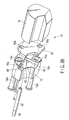
FIG. 3A is an exploded perspective view showing the LED unit of the embodiment of the present invention; -
FIG. 3B is another exploded perspective view showing the LED unit of the embodiment of the present invention; -
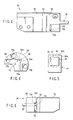
FIG. 4 is a schematic diagram showing the positioning of an LED and a light guide holding member of the embodiment of the present invention; -
FIG. 5 is a schematic diagram showing the positioning of the LED and a light guide of the embodiment of the present invention; -
FIG. 6 is another side view showing the LED unit of the embodiment of the present invention; and -
FIG. 7 is a side view showing the inner part of a grasping portion of the embodiment of the present invention. - Hereinafter, an embodiment of the present invention will be described with reference to the drawings.
-
FIGS. 1 to 7 show the embodiment of the present invention. - As shown in
FIG. 1 , a portable endoscope of the present embodiment includes anelongated insertion portion 8 to be inserted into a body cavity. In theinsertion portion 8, a distal endrigid portion 10 having rigidity, abending portion 12 to be operated to be bent, and aninsertion tube portion 14 being elongated and having flexibility are arranged from a distal end side to a proximal end side. The proximal end portion of theinsertion portion 8 is connected to anoperating portion 16 to be grasped and operated by an operator. Theoperating portion 16 is formed of a distal endside grasping portion 18 and a proximal end side operating portionmain body 20. - An
LED unit 34 as a light source unit to generate illuminative light is built in thegrasping portion 18. One end portion of alight guide 36 as a light transmission member is connected to theLED unit 34. Thelight guide 36 is inserted through theoperating portion 16 and theinsertion portion 8 to be extended to the distal endrigid portion 10 of theinsertion portion 8. In the distal endrigid portion 10, the distal end portion of thelight guide 36 is connected to an illumination optical system, and anillumination window 38 is arranged on the distal end side of the illumination optical system. The illuminative light generated by theLED unit 34 is guided by thelight guide 36 to irradiate an observation target from theillumination window 38 via the illumination optical system. On the other hand, in the distal endrigid portion 10, an observation optical system is arranged on the proximal end side of anobservation window 40, and the distal end portion of animage guide 42 is connected to the observation optical system. Theimage guide 42 is inserted through theinsertion portion 8 and theoperating portion 16 to be extended to the operating portionmain body 20. In the operating portionmain body 20, the proximal end portion of theimage guide 42 is connected to animage pickup unit 44. An observation image is formed on the distal end surface of theimage guide 42 by the observation optical system via theobservation window 40, transmitted by theimage guide 42 and picked by theimage pickup unit 44. - A
display device 26 to display the observation image picked by theimage pickup unit 44 is connected to the operating portionmain body 20. Thedisplay device 26 is provided with amonitor 28 to display the observation image and achangeover switch 30 to switch the observation image to be recorded between a dynamic image and a static image. Moreover, thedisplay device 26 is provided with a battery as a power source for the whole portable endoscope, and astorage portion 32 to receive a recording medium for recording the image. - In addition, the operating portion
main body 20 is provided with a switch to record or reproduce the observation image, abending operation lever 22 to make thebending portion 12 to be operated to be bent, and the like. - The
LED unit 34 will be described with reference toFIGS. 2 to 6 . - A positioning mechanism in the
LED unit 34 will hereinafter be described. - As shown in
FIGS. 2 ,3A and3B , in theLED unit 34, anLED 46 as a light source is mounted on anLED substrate 52 as a light source holding member. Here, in theLED substrate 52, the surface on which theLED 46 is mounted is referred to as a mounting surface, and the surface opposite to the mounting surface is referred to as a back surface. TheLED 46 has a rectangular parallelepiped shape, and includes a bottom surface, a top surface and first to fourth side surfaces. TheLED substrate 52 is arranged on the bottom surface side of theLED 46. A squarelight emission surface 48 as a light emitting portion is arranged on the top surface of theLED 46. Among the first to fourth side surfaces of theLED 46, the first andsecond side surfaces LED 46 is substantially orthogonal to theLED substrate 52, and the normal directions of the first andsecond side surfaces LED 46. - A light
guide holding member 58 as a light transmission member holding member is arranged on the mounting surface side of theLED substrate 52. The lightguide holding member 58 has a substantially columnar shape, and the axial direction thereof is substantially orthogonal to theLED substrate 52. Here, alight guide connecter 62 is fitted over the proximal end portion of thelight guide 36. A lightguide insertion hole 60 through which thelight guide connecter 62 is to be inserted is formed in the axial direction through the lightguide holding member 58. A fixingscrew hole 64 is bored from the outer peripheral surface of the lightguide holding member 58 to the lightguide insertion hole 60, and screwing a fixingscrew 66 into the fixingscrew hole 64 enables fixing of thelight guide connecter 62 to the lightguide holding member 58. - In the light
guide holding member 58, a protruding shape in the axial direction is formed on the end surface portion on theLED substrate 52 side. First and second wall surfaces 70a, 70b forming a positioning portion are formed of the side surfaces of the protruding shape. The first and second wall surfaces 70a, 70b are substantially parallel to the axial direction and orthogonal to each other, and are to be abutted on the first andsecond side surfaces LED 46, respectively. As shown inFIG. 4 , abutting the first and second wall surfaces 70a, 70b on the first andsecond side surfaces guide holding member 58 and theLED 46. When the lightguide holding member 58 and theLED 46 are mutually positioned, an opening portion of the lightguide insertion hole 60 of the lightguide holding member 58 is arranged so as to face the top surface of theLED 46, the proximal end portion of thelight guide connecter 62 inserted into the lightguide insertion hole 60 is abutted on the top surface of theLED 46, and the proximal end surface of thelight guide 36 is arranged so as to face thelight emission surface 48 of theLED 46. Here, the proximal end surface of thelight guide 36 forms anincidence surface 37 as an incident portion wherein the illuminative light is to enter the incident portion. Furthermore, in order to minimize the loss of a light quantity when the illuminative light enters theincidence surface 37 from thelight emission surface 48, as shown inFIG. 5 , theincidence surface 37 and thelight emission surface 48 are arranged so that the centers thereof match with each other. - Furthermore, in the light
guide holding member 58, anopen portion 72 forming an observing portion is formed so as to open outwardly from the first andsecond side surfaces FIG. 6 , when the end surface of the protruding shape of the lightguide holding member 58 is abutted on theLED substrate 52 and the first andsecond side surfaces LED 46 are arranged in the vicinity of the first and second wall surfaces 70a, 70b of the lightguide holding member 58, respectively, an abutment states between the first and second wall surfaces 70a, 70b and the first andsecond side surfaces open portion 72, respectively. It is to be noted that in the present embodiment, the integralopen portion 72 is used, but two separate open portions may be used in observing an abutment state between thefirst wall surface 70a and thefirst side surface 50a and observing an abutment state between thesecond wall surface 70b and thesecond side surface 50b. - An adjustment joining mechanism of the
light source unit 34 will hereinafter be described. - As shown in
FIGS. 2 ,3A and3B , in the outer peripheral portion of the lightguide holding member 58, first andsecond groove portions LED substrate 52 to a position before the end surface on theLED substrate 52 side. First and second holdingmember insertion holes end surfaces second groove portions LED substrate 52 side. First and second joiningscrews member insertion holes screws second groove portions - Moreover, first and second
substrate insertion holes LED substrate 52 orthogonal to theLED substrate 52 and the first and second joiningscrews substrate insertion holes - An LED
substrate sandwiching member 78 as a substrate holding member sandwiching member is arranged on the back surface side of theLED substrate 52.
First and secondsandwiching screw holes LED substrate 52 side end surface of the LEDsubstrate sandwiching member 78 and the first and second joiningscrews sandwiching screw holes - Inserting the first and second joining
screws member insertion holes guide holding member 58 and the first and secondsubstrate insertion holes LED substrate 52, respectively, and screwing the first and second joiningscrews sandwiching screw holes substrate sandwiching member 78, respectively, enable to sandwich theLED substrate 52 between the lightguide holding member 58 and the LEDsubstrate sandwiching member 78. That is, the end surface of the protruding shape of the lightguide holding member 58 is to be brought into face contact with the mounting surface of theLED substrate 52, and the end surface of the LEDsubstrate sandwiching member 78 is to be brought into face contact with the back surface of theLED substrate 52. Furthermore, the inner diameter of the first and second holdingmember insertion holes substrate insertion holes screws guide holding member 58, theLED substrate 52 and the LEDsubstrate sandwiching member 78, it is enabled to adjust the relative positions of the lightguide holding member 58, theLED substrate 52 and the LEDsubstrate sandwiching member 78 in a direction orthogonal to the axial direction. - It is to be noted that a
cable 54 for transmitting an electric signal or the like to theLED 46 is extended from theLED substrate 52. Furthermore, acable insertion hole 68 is formed through the lightguide holding member 58 in the axial direction and thecable 54 extended from theLED substrate 52 is to be inserted through thecable insertion hole 68. - A mounting mechanism of the
LED unit 34 in the graspingportion 18 of the endoscope will hereinafter be described. - As shown in
FIG. 7 , aplanar portion 82 is formed substantially parallel to the axial direction on the outer peripheral portion of the LEDsubstrate sandwiching member 78 of theLED unit 34. Theplanar portion 82 of the LEDsubstrate sandwiching member 78 is brought into face contact with aradiator frame 84, and fixed thereto with screws. Theradiator frame 84 is brought into face contact with a graspingportion frame 86 arranged in the grasping portion, and fixed thereto with screws. - The
LED unit 34 is arranged so that the LEDsubstrate sandwiching member 78 is disposed on the distal end side and the lightguide holding member 58 is disposed on the proximal end side. Thelight guide 36 is protruded from theLED unit 34 to the proximal end side, is then gradually turned back and extended along the outer side of the graspingportion frame 86 from the proximal end side to the distal end side, and is introduced into the insertion portion. Thus, even when thelight guide 36 has an extra length, it is enabled to receive thelight guide 36 in the grasping portion without load of any excessive stress. - Next, an assembly method of the
LED unit 34 will be described. - When assembling the
LED unit 34, thecable 54 extended from theLED substrate 52 is inserted through thecable insertion hole 68 of the lightguide holding member 58. Subsequently, the first and second joiningscrews member insertion holes guide holding member 58 and the first and secondsubstrate insertion holes LED substrate 52, respectively, and are screwed into the first and secondsandwiching screw holes substrate sandwiching member 78, respectively. During this, the relative positions of the lightguide holding member 58 and theLED substrate 52 are adjusted with respect to a direction orthogonal to the axial direction, and the first and second wall surfaces 70a, 70b of the lightguide holding member 58 are abutted on the first andsecond side surfaces LED 46, and so the lightguide holding member 58 and theLED 46 are positioned. In a state where the first and second wall surfaces 70a, 70b completely abut on the first andsecond side surfaces screws sandwiching screw holes LED substrate 52 is securely sandwiched between the lightguide holding member 58 and the LEDsubstrate sandwiching member 78. It is to be noted that in a joining operation, it is possible to appropriately adjust the relative position of the LEDsubstrate sandwiching member 78 with respect to the lightguide holding member 58 and theLED substrate 52 with respect to the direction orthogonal to the axial direction. As occasion demand, an abutment states between the first and second wall surfaces 70a, 70b of the lightguide holding member 58 and the first andsecond side surfaces LED 46 are confirmed by visual inspection or use of a microscope via theopen portion 72 of the lightguide holding member 58. Subsequently, thelight guide connecter 62 is inserted through the lightguide insertion hole 60 of the lightguide holding member 58, the proximal end portion of thelight guide connecter 62 is abutted on theLED 46, and thelight guide connecter 62 is fixed to the lightguide holding member 58 with the fixingscrew 66. Consequently, theincidence surface 37 of thelight guide 36 faces thelight emission surface 48 of theLED 46, and the center of the incidence surface matches that of thelight emission surface 48 of theLED 46. Thus, theLED unit 34 is assembled. - Subsequently, a heat release function in the
LED unit 34 will be described. - The
LED 46 has a high temperature due to light emission. Heat generated in theLED 46 is released to the lightguide holding member 58 via the first and second wall surfaces 70a, 70b as a heat release portion of the lightguide holding member 58, which is brought into face contact with the first andsecond side surfaces LED 46, via thelight guide connecter 62 from thelight emission surface 48, and directly by radiation. Moreover, the heat transmitted from theLED 46 to theLED substrate 52 is released to the lightguide holding member 58 via the end surface of the protruding shape of the lightguide holding member 58, which is brought into face contact with the mounting surface of theLED substrate 52, and is released to the LEDsubstrate sandwiching member 78 via the end surface of the LEDsubstrate sandwiching member 78, which is brought into face contact with the back surface of theLED substrate 52. The heat transmitted to the LEDsubstrate sandwiching member 78 is further released to theradiator frame 84 and the graspingportion frame 86. Thus, the lightguide holding member 58 and the LEDsubstrate sandwiching member 78 also have a heat release function. - Therefore, the
LED unit 34 of the present embodiment produces the following effects. - In the
LED unit 34 of the present embodiment, just only abutting the first andsecond side surfaces LED 46 on the first and second wall surfaces 70a, 70b of the lightguide holding member 58, respectively, and then joining the lightguide holding member 58 and the LEDsubstrate sandwiching member 78 to sandwich theLED substrate 52 therebetween enable correct positioning of thelight emission surface 48 of theLED 46 and theincidence surface 37 of thelight guide 36 with respect to the direction orthogonal to the light emitting direction of thelight emission surface 48. That is, it is enabled to easily and correctly position thelight emission surface 48 of theLED 46 and theincidence surface 37 of thelight guide 36. - It is to be noted that since the abutment states between the first and
second side surfaces open portion 72 of the lightguide holding member 58, it is enabled to easily and securely abut the first andsecond side surfaces - Moreover, since the relative positions of the light
guide holding member 58, theLED substrate 52 and the LEDsubstrate sandwiching member 78 is adjustable with respect to the direction orthogonal to the axial direction, it is enabled to sufficiently secure an adjustable range with a compact constitution, in particular, as compared with a case where the relative positions of the lightguide holding member 58 and the LEDsubstrate sandwiching member 78 or the relative positions of theLED substrate 52 and the LEDsubstrate sandwiching member 78 is not adjustable. - Furthermore, in the
LED unit 34, the first and second wall surfaces 70a, 70b of the lightguide holding member 58 are brought into face contact with the first andsecond side surfaces LED 46, the proximal end surface of thelight guide connecter 62 is abutted on the top surface of theLED 46, and the end surface of the protruding shape of the lightguide holding member 58 and the end surface of the LEDsubstrate sandwiching member 78 are brought into face contact with theLED substrate 52, and so the lightguide holding member 58 and the LEDsubstrate sandwiching member 78 is used in releasing the heat from theLED 46. Therefore, the heat release efficiency of theLED 46 is improved.
Claims (12)
- A light source unit characterized by comprising:a light source (46) including a light emitting portion (48);a light source holding member (52) holding the light source (46);a light transmission member (36) including an incident portion (37) wherein light from the light emitting portion (48) is to enter the incident portion (37);a light transmission member holding member (58) holding the light transmission member (36);a positioning portion (70a; 70b) provided on the light transmission member holding member (58) and abutted on the light source (46) to position the light transmission member holding member (58) and the light source (46) to position the incident portion (37) and the light emitting portion (48); andan adjustment joining mechanism (56a, 56b, 74a, 74b, 75a, 75b, 76a, 76b, 78, 80a, 80b) configured to join the light transmission member holding member (58) and the light source holding member (52) to each other so as to adjust the relative positions of the light transmission member holding member (58) and the light source holding member (52), and joining the light transmission member holding member (58) and the light source holding member (52) to each other in a state where the light source (46) and the positioning portion (70a; 70b) abut on each other.
- The light source unit according to claim 1, characterized in that
the light source (46) includes a side surface (50a; 50b) and the normal direction of the side surface (50a; 50b) forms an angle with respect to a light emitting direction of the light emitting portion (48), and
the positioning portion (70a; 70b) includes a wall surface (70a; 70b) abutting on the side surface (50a; 50b). - The light source unit according to claim 1, characterized in that
the light source (46) includes first and second side surfaces (50a; 50b) and the normal directions of the first and second side surfaces (50a; 50b) form angles with respect to a light emitting direction of the light emitting portion (48) and face different directions with respect to each other, and
the positioning portion (70a; 70b) includes a first wall surface (70a) abutting on the first side surface (50a) and a second wall surface (70b) abutting on the second side surface (50b). - The light source unit according to claim 1, characterized in that
the light transmission member holding member (58) includes an observing portion (72) provided in the light transmission member holding member (58) and an abutment state between the light source (46) and the positioning portion (70a; 70b) is observable through the observing portion (72). - The light source unit according to claim 2, characterized in that
the light transmission member holding member (58) includes an open portion (72) extending outwardly from the wall surface (70a; 70b) in the light transmission member holding member (58) and an abutment state between the side surface (50a; 50b) and the wall surface (70a; 70b) is observable through the open portion (72). - The light source unit according to claim 3, characterized in that
the light transmission member holding member (58) includes a first open portion (72) extending outwardly from the first wall surface (70a) in the light transmission member holding member (58) and a second open portion (72) extending outwardly from the second wall surface (70b) in the light transmission member holding member (58), and an abutment state between the first side surface (50a) and the first wall surface (70a) is observable through the first open portion (72) and an abutment state between the second side surface (50b) and the second wall surface (70b) is observable through the second open portion (72). - The light source unit according to claim 1, characterized in that
the adjustment joining mechanism (56a, 56b, 74a, 74b, 75a, 75b, 76a, 76b, 78, 80a, 80b) includes a light source holding member sandwiching member (78), and
the light transmission member holding member (58) and the light source holding member sandwiching member (78) are configured to sandwich the light source holding member (52) so as to adjust the relative positions of the light source holding member (52) with respect to the light transmission member holding member (58). - The light source unit according to claim 7, characterized in that
the adjustment joining mechanism (56a, 56b, 74a, 74b, 75a, 75b, 76a, 76b, 78, 80a, 80b) is configured to join the light transmission member holding member (58) and the light source holding member sandwiching member (78) to each other so as to adjust the relative positions of the light transmission member holding member (58) and the light source holding member sandwiching member (78). - The light source unit according to claim 1, characterized in that
the light transmission member holding member (58) includes a heat release portion (70a; 70b) to release heat generated in the light source (46). - The light source unit according to claim 9, characterized in that
the heat release portion (70a; 70b) is provided on the positioning portion (70a; 70b). - The light source unit according to claim 7, characterized in that
the light source holding member sandwiching member (78) includes a heat release function of releasing heat generated in the light source (46). - An endoscope characterized by comprising the light source unit (34) according to any one of claims 1 to 11.
Applications Claiming Priority (1)
| Application Number | Priority Date | Filing Date | Title |
|---|---|---|---|
| JP2007294709A JP5284625B2 (en) | 2007-11-13 | 2007-11-13 | Light source unit |
Publications (3)
| Publication Number | Publication Date |
|---|---|
| EP2060223A2 true EP2060223A2 (en) | 2009-05-20 |
| EP2060223A3 EP2060223A3 (en) | 2013-08-07 |
| EP2060223B1 EP2060223B1 (en) | 2017-08-30 |
Family
ID=40380762
Family Applications (1)
| Application Number | Title | Priority Date | Filing Date |
|---|---|---|---|
| EP08017150.7A Not-in-force EP2060223B1 (en) | 2007-11-13 | 2008-09-29 | Light source unit |
Country Status (4)
| Country | Link |
|---|---|
| US (1) | US7712940B2 (en) |
| EP (1) | EP2060223B1 (en) |
| JP (1) | JP5284625B2 (en) |
| CN (1) | CN101435556B (en) |
Cited By (1)
| Publication number | Priority date | Publication date | Assignee | Title |
|---|---|---|---|---|
| EP3125740B1 (en) * | 2014-04-04 | 2023-07-26 | Boston Scientific Scimed, Inc. | Medical system and related methods for diagnosis and treatment |
Families Citing this family (9)
| Publication number | Priority date | Publication date | Assignee | Title |
|---|---|---|---|---|
| JP5519211B2 (en) | 2009-08-10 | 2014-06-11 | オリンパス株式会社 | Endoscope device |
| CN103002791B (en) * | 2010-07-14 | 2015-09-09 | 奥林巴斯医疗株式会社 | Endoscope light source unit and endoscopic system |
| JP6081208B2 (en) * | 2013-01-31 | 2017-02-15 | オリンパス株式会社 | Endoscope |
| JP6266173B2 (en) * | 2016-01-20 | 2018-01-24 | オリンパス株式会社 | Portable endoscope |
| WO2018076180A1 (en) * | 2016-10-25 | 2018-05-03 | 深圳迈瑞生物医疗电子股份有限公司 | Medical light-source apparatus |
| JP6395973B1 (en) * | 2017-02-22 | 2018-09-26 | オリンパス株式会社 | Endoscope operation section and endoscope having the same |
| CN111887799B (en) * | 2020-08-31 | 2025-06-13 | 深圳市精锋医疗科技股份有限公司 | Electronic endoscopes and surgical robots |
| DE102021105469B3 (en) * | 2021-03-08 | 2022-04-21 | Pentax Medical Bulgaria Ltd. | Endoscope with holder for inserting a light guide |
| US12585103B2 (en) * | 2023-06-22 | 2026-03-24 | Olympus Medical Systems Corp. | Image capturing unit and endoscope |
Citations (1)
| Publication number | Priority date | Publication date | Assignee | Title |
|---|---|---|---|---|
| JP2005211204A (en) | 2004-01-28 | 2005-08-11 | Olympus Corp | Endoscope apparatus |
Family Cites Families (9)
| Publication number | Priority date | Publication date | Assignee | Title |
|---|---|---|---|---|
| JPS63243905A (en) * | 1987-03-31 | 1988-10-11 | Fujitsu Ltd | Method for fixing optical semiconductor parts |
| JPH07297479A (en) * | 1994-04-27 | 1995-11-10 | Mitsubishi Electric Corp | Optical semiconductor device and manufacturing method thereof |
| JP2000107125A (en) * | 1998-09-30 | 2000-04-18 | Olympus Optical Co Ltd | Endoscope |
| US7025734B1 (en) * | 2001-09-28 | 2006-04-11 | Advanced Cardiovascular Systmes, Inc. | Guidewire with chemical sensing capabilities |
| JP2006012328A (en) * | 2004-06-28 | 2006-01-12 | Sanyo Electric Co Ltd | Laser holder and optical pickup device |
| JP4679198B2 (en) * | 2004-08-23 | 2011-04-27 | オリンパスメディカルシステムズ株式会社 | Endoscope |
| US20060126080A1 (en) * | 2004-11-30 | 2006-06-15 | Sysmex Corporation | Light irradiating device and particle imaging device comprising the light irradiating device |
| JP4922636B2 (en) * | 2006-03-24 | 2012-04-25 | オリンパスメディカルシステムズ株式会社 | Endoscope |
| JP2008043742A (en) * | 2006-07-20 | 2008-02-28 | Pentax Corp | Electronic endoscope system |
-
2007
- 2007-11-13 JP JP2007294709A patent/JP5284625B2/en active Active
-
2008
- 2008-09-26 CN CN200810166348.2A patent/CN101435556B/en active Active
- 2008-09-29 EP EP08017150.7A patent/EP2060223B1/en not_active Not-in-force
- 2008-09-30 US US12/241,110 patent/US7712940B2/en active Active
Patent Citations (1)
| Publication number | Priority date | Publication date | Assignee | Title |
|---|---|---|---|---|
| JP2005211204A (en) | 2004-01-28 | 2005-08-11 | Olympus Corp | Endoscope apparatus |
Cited By (1)
| Publication number | Priority date | Publication date | Assignee | Title |
|---|---|---|---|---|
| EP3125740B1 (en) * | 2014-04-04 | 2023-07-26 | Boston Scientific Scimed, Inc. | Medical system and related methods for diagnosis and treatment |
Also Published As
| Publication number | Publication date |
|---|---|
| JP5284625B2 (en) | 2013-09-11 |
| JP2009118966A (en) | 2009-06-04 |
| CN101435556A (en) | 2009-05-20 |
| EP2060223B1 (en) | 2017-08-30 |
| CN101435556B (en) | 2010-11-10 |
| US20090122574A1 (en) | 2009-05-14 |
| US7712940B2 (en) | 2010-05-11 |
| EP2060223A3 (en) | 2013-08-07 |
Similar Documents
| Publication | Publication Date | Title |
|---|---|---|
| EP2060223B1 (en) | Light source unit | |
| EP2039285B1 (en) | Illumination apparatus and endoscope | |
| US7128709B2 (en) | Endoscope apparatus | |
| JP5042481B2 (en) | Electronic endoscope | |
| WO2006001377A1 (en) | Endoscope device | |
| JP4922636B2 (en) | Endoscope | |
| US7695202B1 (en) | Visual laser diode to fiber coupling system | |
| JP2009153776A (en) | Endoscope and its manufacturing method, and connector attachable/detachable jig of endoscope | |
| WO2021131027A1 (en) | Camera head adaptor | |
| US12285158B2 (en) | Intraoral measurement device | |
| US12178393B2 (en) | Plug, connector, endoscope apparatus, and endoscope | |
| KR101894866B1 (en) | Medical light source module, and medical light device having the same | |
| JP4511210B2 (en) | Endoscope device | |
| JP2837680B2 (en) | Endoscope device and tip optical adapter | |
| JP2005251588A (en) | Light irradiation device | |
| JP5750615B2 (en) | Part fixing structure | |
| CN223994974U (en) | Fiber optic conduit and coupler connection structure and medical equipment | |
| CN222493893U (en) | Test card mounting assembly and endoscope aligning device | |
| CN223323537U (en) | Strabismus endoscope and endoscope system | |
| JP2008220711A (en) | Distal end of oblique endoscope | |
| CN210408348U (en) | Endoscope optical adapter | |
| JP5075530B2 (en) | Endoscope light source device | |
| WO2018079070A1 (en) | Endoscope | |
| WO2018079077A1 (en) | Endoscope | |
| JP2003126033A (en) | Endoscope |
Legal Events
| Date | Code | Title | Description |
|---|---|---|---|
| PUAI | Public reference made under article 153(3) epc to a published international application that has entered the european phase |
Free format text: ORIGINAL CODE: 0009012 |
|
| AK | Designated contracting states |
Kind code of ref document: A2 Designated state(s): AT BE BG CH CY CZ DE DK EE ES FI FR GB GR HR HU IE IS IT LI LT LU LV MC MT NL NO PL PT RO SE SI SK TR |
|
| AX | Request for extension of the european patent |
Extension state: AL BA MK RS |
|
| PUAL | Search report despatched |
Free format text: ORIGINAL CODE: 0009013 |
|
| AK | Designated contracting states |
Kind code of ref document: A3 Designated state(s): AT BE BG CH CY CZ DE DK EE ES FI FR GB GR HR HU IE IS IT LI LT LU LV MC MT NL NO PL PT RO SE SI SK TR |
|
| AX | Request for extension of the european patent |
Extension state: AL BA MK RS |
|
| RIC1 | Information provided on ipc code assigned before grant |
Ipc: A61B 1/00 20060101ALI20130628BHEP Ipc: A61B 1/005 20060101AFI20130628BHEP Ipc: G02B 6/42 20060101ALI20130628BHEP Ipc: A61B 1/07 20060101ALI20130628BHEP |
|
| 17P | Request for examination filed |
Effective date: 20131030 |
|
| RBV | Designated contracting states (corrected) |
Designated state(s): AT BE BG CH CY CZ DE DK EE ES FI FR GB GR HR HU IE IS IT LI LT LU LV MC MT NL NO PL PT RO SE SI SK TR |
|
| RBV | Designated contracting states (corrected) |
Designated state(s): AT BE BG CH CY CZ DE DK EE ES FI FR GB GR HR HU IE IS IT LI LT LU LV MC MT NL NO PL PT RO SE SI SK TR |
|
| AKX | Designation fees paid |
Designated state(s): AT BE BG CH CY CZ DE DK EE ES FI FR GB GR HR HU IE IS IT LI LT LU LV MC MT NL NO PL PT RO SE SI SK TR |
|
| RAP1 | Party data changed (applicant data changed or rights of an application transferred) |
Owner name: OLYMPUS CORPORATION |
|
| RAP1 | Party data changed (applicant data changed or rights of an application transferred) |
Owner name: OLYMPUS CORPORATION |
|
| RAP1 | Party data changed (applicant data changed or rights of an application transferred) |
Owner name: OLYMPUS CORPORATION |
|
| RIN1 | Information on inventor provided before grant (corrected) |
Inventor name: OGAWA, TOMOAKI |
|
| REG | Reference to a national code |
Ref country code: DE Ref legal event code: R079 Ref document number: 602008051859 Country of ref document: DE Free format text: PREVIOUS MAIN CLASS: A61B0001005000 Ipc: A61B0001060000 |
|
| RIC1 | Information provided on ipc code assigned before grant |
Ipc: A61B 1/07 20060101ALI20170124BHEP Ipc: A61B 1/06 20060101AFI20170124BHEP Ipc: G02B 6/42 20060101ALI20170124BHEP Ipc: A61B 1/005 20060101ALI20170124BHEP Ipc: A61B 1/00 20060101ALI20170124BHEP |
|
| GRAP | Despatch of communication of intention to grant a patent |
Free format text: ORIGINAL CODE: EPIDOSNIGR1 |
|
| INTG | Intention to grant announced |
Effective date: 20170330 |
|
| RIN1 | Information on inventor provided before grant (corrected) |
Inventor name: OGAWA, TOMOAKI |
|
| GRAS | Grant fee paid |
Free format text: ORIGINAL CODE: EPIDOSNIGR3 |
|
| GRAA | (expected) grant |
Free format text: ORIGINAL CODE: 0009210 |
|
| AK | Designated contracting states |
Kind code of ref document: B1 Designated state(s): AT BE BG CH CY CZ DE DK EE ES FI FR GB GR HR HU IE IS IT LI LT LU LV MC MT NL NO PL PT RO SE SI SK TR |
|
| REG | Reference to a national code |
Ref country code: GB Ref legal event code: FG4D |
|
| REG | Reference to a national code |
Ref country code: CH Ref legal event code: EP |
|
| REG | Reference to a national code |
Ref country code: AT Ref legal event code: REF Ref document number: 922720 Country of ref document: AT Kind code of ref document: T Effective date: 20170915 |
|
| REG | Reference to a national code |
Ref country code: IE Ref legal event code: FG4D |
|
| REG | Reference to a national code |
Ref country code: DE Ref legal event code: R096 Ref document number: 602008051859 Country of ref document: DE |
|
| REG | Reference to a national code |
Ref country code: NL Ref legal event code: MP Effective date: 20170830 |
|
| REG | Reference to a national code |
Ref country code: LT Ref legal event code: MG4D |
|
| REG | Reference to a national code |
Ref country code: AT Ref legal event code: MK05 Ref document number: 922720 Country of ref document: AT Kind code of ref document: T Effective date: 20170830 |
|
| PG25 | Lapsed in a contracting state [announced via postgrant information from national office to epo] |
Ref country code: AT Free format text: LAPSE BECAUSE OF FAILURE TO SUBMIT A TRANSLATION OF THE DESCRIPTION OR TO PAY THE FEE WITHIN THE PRESCRIBED TIME-LIMIT Effective date: 20170830 Ref country code: LT Free format text: LAPSE BECAUSE OF FAILURE TO SUBMIT A TRANSLATION OF THE DESCRIPTION OR TO PAY THE FEE WITHIN THE PRESCRIBED TIME-LIMIT Effective date: 20170830 Ref country code: SE Free format text: LAPSE BECAUSE OF FAILURE TO SUBMIT A TRANSLATION OF THE DESCRIPTION OR TO PAY THE FEE WITHIN THE PRESCRIBED TIME-LIMIT Effective date: 20170830 Ref country code: HR Free format text: LAPSE BECAUSE OF FAILURE TO SUBMIT A TRANSLATION OF THE DESCRIPTION OR TO PAY THE FEE WITHIN THE PRESCRIBED TIME-LIMIT Effective date: 20170830 Ref country code: FI Free format text: LAPSE BECAUSE OF FAILURE TO SUBMIT A TRANSLATION OF THE DESCRIPTION OR TO PAY THE FEE WITHIN THE PRESCRIBED TIME-LIMIT Effective date: 20170830 Ref country code: NO Free format text: LAPSE BECAUSE OF FAILURE TO SUBMIT A TRANSLATION OF THE DESCRIPTION OR TO PAY THE FEE WITHIN THE PRESCRIBED TIME-LIMIT Effective date: 20171130 |
|
| PGFP | Annual fee paid to national office [announced via postgrant information from national office to epo] |
Ref country code: DE Payment date: 20170928 Year of fee payment: 10 |
|
| PG25 | Lapsed in a contracting state [announced via postgrant information from national office to epo] |
Ref country code: LV Free format text: LAPSE BECAUSE OF FAILURE TO SUBMIT A TRANSLATION OF THE DESCRIPTION OR TO PAY THE FEE WITHIN THE PRESCRIBED TIME-LIMIT Effective date: 20170830 Ref country code: BG Free format text: LAPSE BECAUSE OF FAILURE TO SUBMIT A TRANSLATION OF THE DESCRIPTION OR TO PAY THE FEE WITHIN THE PRESCRIBED TIME-LIMIT Effective date: 20171130 Ref country code: GR Free format text: LAPSE BECAUSE OF FAILURE TO SUBMIT A TRANSLATION OF THE DESCRIPTION OR TO PAY THE FEE WITHIN THE PRESCRIBED TIME-LIMIT Effective date: 20171201 Ref country code: IS Free format text: LAPSE BECAUSE OF FAILURE TO SUBMIT A TRANSLATION OF THE DESCRIPTION OR TO PAY THE FEE WITHIN THE PRESCRIBED TIME-LIMIT Effective date: 20171230 Ref country code: ES Free format text: LAPSE BECAUSE OF FAILURE TO SUBMIT A TRANSLATION OF THE DESCRIPTION OR TO PAY THE FEE WITHIN THE PRESCRIBED TIME-LIMIT Effective date: 20170830 |
|
| PG25 | Lapsed in a contracting state [announced via postgrant information from national office to epo] |
Ref country code: NL Free format text: LAPSE BECAUSE OF FAILURE TO SUBMIT A TRANSLATION OF THE DESCRIPTION OR TO PAY THE FEE WITHIN THE PRESCRIBED TIME-LIMIT Effective date: 20170830 |
|
| PG25 | Lapsed in a contracting state [announced via postgrant information from national office to epo] |
Ref country code: DK Free format text: LAPSE BECAUSE OF FAILURE TO SUBMIT A TRANSLATION OF THE DESCRIPTION OR TO PAY THE FEE WITHIN THE PRESCRIBED TIME-LIMIT Effective date: 20170830 Ref country code: RO Free format text: LAPSE BECAUSE OF FAILURE TO SUBMIT A TRANSLATION OF THE DESCRIPTION OR TO PAY THE FEE WITHIN THE PRESCRIBED TIME-LIMIT Effective date: 20170830 Ref country code: PL Free format text: LAPSE BECAUSE OF FAILURE TO SUBMIT A TRANSLATION OF THE DESCRIPTION OR TO PAY THE FEE WITHIN THE PRESCRIBED TIME-LIMIT Effective date: 20170830 Ref country code: CZ Free format text: LAPSE BECAUSE OF FAILURE TO SUBMIT A TRANSLATION OF THE DESCRIPTION OR TO PAY THE FEE WITHIN THE PRESCRIBED TIME-LIMIT Effective date: 20170830 |
|
| REG | Reference to a national code |
Ref country code: CH Ref legal event code: PL |
|
| PG25 | Lapsed in a contracting state [announced via postgrant information from national office to epo] |
Ref country code: MC Free format text: LAPSE BECAUSE OF FAILURE TO SUBMIT A TRANSLATION OF THE DESCRIPTION OR TO PAY THE FEE WITHIN THE PRESCRIBED TIME-LIMIT Effective date: 20170830 Ref country code: IT Free format text: LAPSE BECAUSE OF FAILURE TO SUBMIT A TRANSLATION OF THE DESCRIPTION OR TO PAY THE FEE WITHIN THE PRESCRIBED TIME-LIMIT Effective date: 20170830 Ref country code: EE Free format text: LAPSE BECAUSE OF FAILURE TO SUBMIT A TRANSLATION OF THE DESCRIPTION OR TO PAY THE FEE WITHIN THE PRESCRIBED TIME-LIMIT Effective date: 20170830 Ref country code: SK Free format text: LAPSE BECAUSE OF FAILURE TO SUBMIT A TRANSLATION OF THE DESCRIPTION OR TO PAY THE FEE WITHIN THE PRESCRIBED TIME-LIMIT Effective date: 20170830 |
|
| REG | Reference to a national code |
Ref country code: DE Ref legal event code: R097 Ref document number: 602008051859 Country of ref document: DE |
|
| REG | Reference to a national code |
Ref country code: IE Ref legal event code: MM4A |
|
| REG | Reference to a national code |
Ref country code: BE Ref legal event code: MM Effective date: 20170930 |
|
| PG25 | Lapsed in a contracting state [announced via postgrant information from national office to epo] |
Ref country code: LU Free format text: LAPSE BECAUSE OF NON-PAYMENT OF DUE FEES Effective date: 20170929 |
|
| PLBE | No opposition filed within time limit |
Free format text: ORIGINAL CODE: 0009261 |
|
| STAA | Information on the status of an ep patent application or granted ep patent |
Free format text: STATUS: NO OPPOSITION FILED WITHIN TIME LIMIT |
|
| GBPC | Gb: european patent ceased through non-payment of renewal fee |
Effective date: 20171130 |
|
| PG25 | Lapsed in a contracting state [announced via postgrant information from national office to epo] |
Ref country code: IE Free format text: LAPSE BECAUSE OF NON-PAYMENT OF DUE FEES Effective date: 20170929 Ref country code: LI Free format text: LAPSE BECAUSE OF NON-PAYMENT OF DUE FEES Effective date: 20170930 Ref country code: CH Free format text: LAPSE BECAUSE OF NON-PAYMENT OF DUE FEES Effective date: 20170930 |
|
| 26N | No opposition filed |
Effective date: 20180531 |
|
| REG | Reference to a national code |
Ref country code: FR Ref legal event code: ST Effective date: 20180713 |
|
| PG25 | Lapsed in a contracting state [announced via postgrant information from national office to epo] |
Ref country code: SI Free format text: LAPSE BECAUSE OF FAILURE TO SUBMIT A TRANSLATION OF THE DESCRIPTION OR TO PAY THE FEE WITHIN THE PRESCRIBED TIME-LIMIT Effective date: 20170830 Ref country code: BE Free format text: LAPSE BECAUSE OF NON-PAYMENT OF DUE FEES Effective date: 20170930 |
|
| PG25 | Lapsed in a contracting state [announced via postgrant information from national office to epo] |
Ref country code: MT Free format text: LAPSE BECAUSE OF NON-PAYMENT OF DUE FEES Effective date: 20170929 |
|
| PG25 | Lapsed in a contracting state [announced via postgrant information from national office to epo] |
Ref country code: FR Free format text: LAPSE BECAUSE OF NON-PAYMENT OF DUE FEES Effective date: 20171030 |
|
| PG25 | Lapsed in a contracting state [announced via postgrant information from national office to epo] |
Ref country code: GB Free format text: LAPSE BECAUSE OF NON-PAYMENT OF DUE FEES Effective date: 20171130 |
|
| REG | Reference to a national code |
Ref country code: DE Ref legal event code: R119 Ref document number: 602008051859 Country of ref document: DE |
|
| PG25 | Lapsed in a contracting state [announced via postgrant information from national office to epo] |
Ref country code: HU Free format text: LAPSE BECAUSE OF FAILURE TO SUBMIT A TRANSLATION OF THE DESCRIPTION OR TO PAY THE FEE WITHIN THE PRESCRIBED TIME-LIMIT; INVALID AB INITIO Effective date: 20080929 |
|
| PG25 | Lapsed in a contracting state [announced via postgrant information from national office to epo] |
Ref country code: DE Free format text: LAPSE BECAUSE OF NON-PAYMENT OF DUE FEES Effective date: 20190402 |
|
| PG25 | Lapsed in a contracting state [announced via postgrant information from national office to epo] |
Ref country code: CY Free format text: LAPSE BECAUSE OF NON-PAYMENT OF DUE FEES Effective date: 20170830 |
|
| PG25 | Lapsed in a contracting state [announced via postgrant information from national office to epo] |
Ref country code: TR Free format text: LAPSE BECAUSE OF FAILURE TO SUBMIT A TRANSLATION OF THE DESCRIPTION OR TO PAY THE FEE WITHIN THE PRESCRIBED TIME-LIMIT Effective date: 20170830 |
|
| PG25 | Lapsed in a contracting state [announced via postgrant information from national office to epo] |
Ref country code: PT Free format text: LAPSE BECAUSE OF FAILURE TO SUBMIT A TRANSLATION OF THE DESCRIPTION OR TO PAY THE FEE WITHIN THE PRESCRIBED TIME-LIMIT Effective date: 20170830 |