EP2059053A2 - Method and device for generating depth image using reference image, method for encoding/decoding depth image, and encoder or decoder for the same - Google Patents
Method and device for generating depth image using reference image, method for encoding/decoding depth image, and encoder or decoder for the same Download PDFInfo
- Publication number
- EP2059053A2 EP2059053A2 EP20080105614 EP08105614A EP2059053A2 EP 2059053 A2 EP2059053 A2 EP 2059053A2 EP 20080105614 EP20080105614 EP 20080105614 EP 08105614 A EP08105614 A EP 08105614A EP 2059053 A2 EP2059053 A2 EP 2059053A2
- Authority
- EP
- European Patent Office
- Prior art keywords
- image
- depth image
- hole
- reference image
- depth
- Prior art date
- Legal status (The legal status is an assumption and is not a legal conclusion. Google has not performed a legal analysis and makes no representation as to the accuracy of the status listed.)
- Withdrawn
Links
Images



Classifications
-
- H—ELECTRICITY
- H04—ELECTRIC COMMUNICATION TECHNIQUE
- H04N—PICTORIAL COMMUNICATION, e.g. TELEVISION
- H04N13/00—Stereoscopic video systems; Multi-view video systems; Details thereof
-
- H—ELECTRICITY
- H04—ELECTRIC COMMUNICATION TECHNIQUE
- H04N—PICTORIAL COMMUNICATION, e.g. TELEVISION
- H04N19/00—Methods or arrangements for coding, decoding, compressing or decompressing digital video signals
-
- G—PHYSICS
- G06—COMPUTING OR CALCULATING; COUNTING
- G06T—IMAGE DATA PROCESSING OR GENERATION, IN GENERAL
- G06T1/00—General purpose image data processing
-
- H—ELECTRICITY
- H04—ELECTRIC COMMUNICATION TECHNIQUE
- H04N—PICTORIAL COMMUNICATION, e.g. TELEVISION
- H04N19/00—Methods or arrangements for coding, decoding, compressing or decompressing digital video signals
- H04N19/50—Methods or arrangements for coding, decoding, compressing or decompressing digital video signals using predictive coding
- H04N19/59—Methods or arrangements for coding, decoding, compressing or decompressing digital video signals using predictive coding involving spatial sub-sampling or interpolation, e.g. alteration of picture size or resolution
-
- H—ELECTRICITY
- H04—ELECTRIC COMMUNICATION TECHNIQUE
- H04N—PICTORIAL COMMUNICATION, e.g. TELEVISION
- H04N19/00—Methods or arrangements for coding, decoding, compressing or decompressing digital video signals
- H04N19/50—Methods or arrangements for coding, decoding, compressing or decompressing digital video signals using predictive coding
- H04N19/597—Methods or arrangements for coding, decoding, compressing or decompressing digital video signals using predictive coding specially adapted for multi-view video sequence encoding
-
- H—ELECTRICITY
- H04—ELECTRIC COMMUNICATION TECHNIQUE
- H04N—PICTORIAL COMMUNICATION, e.g. TELEVISION
- H04N19/00—Methods or arrangements for coding, decoding, compressing or decompressing digital video signals
- H04N19/60—Methods or arrangements for coding, decoding, compressing or decompressing digital video signals using transform coding
- H04N19/61—Methods or arrangements for coding, decoding, compressing or decompressing digital video signals using transform coding in combination with predictive coding
Definitions
- the present invention relates to a method and device for generating a depth image using a reference image, a method for encoding/decoding the depth image, and an encoder/decoder for the same. More particularly, the present invention relates to a method and device for generating a depth image, a method for encoding/decoding the depth image, an encoder/decoder for the same, and a recording medium recording an image generated by the method, which are related to a depth image encoding method that can effectively reduce a bit generation rate using a reference image obtained by at least one camera and improve encoding efficiency.
- a three-dimensional video processing technology as a core technology of the next-generation information communication service field is a state-of-the-art technology for which technology development competition is keen with the development to an information industry society.
- the three-dimensional video processing technology is an essential element to provide a high-quality image service in a multimedia application.
- the application field of the three-dimensional video processing technology is diversified into various application fields such as broadcasting, medical care, education (or discipline), military affairs, games, animation, or virtual reality as well as the field of information and communication.
- the three-dimensional video processing technology is considered as the next-generation of realistic three-dimensional multimedia information communication core technology, which is commonly required in a variety of fields, and has been studied by advanced countries.
- the three-dimensional video may be defined from two standpoints as follows. First, the three-dimensional video may be defined as video that is configured such that depth information is applied to an image and a user feels that a portion of the image protrudes from a screen. Second, the three-dimensional video may be defined as video that is configured such that various viewpoints are provided and a user feels reality (that is, three-dimensional impression) from an image. This three-dimensional video may be classified into stereoscopic type, a multi-view type, an integral photography (IP) type, a multi-view (omni) type, a panorama type, and a hologram type in accordance with an acquisition method, depth impression, and a display method. In addition, examples of a method that represents three-dimensional video include an image-based reconstruction method and a mesh-based representation method.
- depth image-based rendering has attracted attention as the method that represents the three-dimensional video.
- the depth image-based rendering generates scenes at different viewpoints using reference images that have information such as a depth or a different angle for each pixel.
- a three-dimensional model having a complicated shape, which is not easy to represent, can be easily rendered, a signal processing method such as general image filtering can be applied, and high-quality three-dimensional video can be generated.
- the depth image-based rendering uses a depth image (or depth map) and a texture image (or color image) that are acquired through a depth camera and a multi-view camera.
- the depth image is used to represent a three-dimensional model to be realistic (that is, to generate three-dimensional video).
- the depth image may be defined as an image that represents a distance between an object on a three-dimensional space and a camera used to photograph the object in a black-and-white unit.
- the depth image is widely used in a three-dimensional restoration technology or a three-dimensional warphing technology based on depth information and camera parameters.
- the depth image is applied in a variety of fields, and a representative example thereof is a free viewpoint TV.
- the free viewpoint TV is a TV where a user does not view an image at only a predetermined viewpoint but views an image at any viewpoint according to the selection from the user. Since the free viewpoint TV has the above-described characteristics, images can be generated at any viewpoint in consideration of multi-view images photographed by a plurality of cameras and multi-view depth images corresponding to the multi-view images.
- the depth image may include depth information at a single viewpoint.
- the depth image needs to include depth information at multi-viewpoints to achieve the above-described characteristics. Even if the multi-view depth image is configured more constantly than the texture image, the multi-view depth image has a large amount of data according to encoding. Accordingly, an effective video compression technology is essentially required in the depth image.
- an encoding method of a multi-view depth image has been studied by the MPEG Standardization Organization. For example, there is a method that uses texture images that are obtained by photographing one scene using a plurality of cameras in consideration of a relationship between adjacent images. This method can improve encoding efficiency, because there remains a large amount of information obtained from the texture images. If the correlation between the temporal direction and the spatial direction is considered, it is possible to further improve encoding efficiency. However, there is a problem in that this method is inefficient in terms of time or costs.
- the multi-view depth image encoding method that is suggested in the document follows the existing multi-view image encoding method, because multi-view depth image encoding method considers a relationship between the view-point directions having characteristics similar to those of the adjacent multi-view images instead of the multi-view images.
- the invention has been made to solve the above-described problems, and it is an object of the invention to provide a method and device for generating a depth image using a reference image, a method for encoding/decoding the depth image, an encoder/decoder for the same, and a recording medium recording an image generated by the method, which can use a down-sampling method that reduces a size of a depth image having a simpler pixel value than a texture image.
- a depth image generating method includes: a step (a) of obtaining a depth image at a viewpoint and setting the obtained depth image to a reference image; a step (b) of applying a 3D warphing method to the reference image and predicting and generating a depth image at a specific viewpoint; and a step (c) of removing a hole that exists in the predicted and generated depth image.
- the reference image may be down-sampled.
- the step (b) may include: a step (b1) of projecting positions of pixel values existing in the reference image onto a three-dimensional space; a step (b2) of reprojecting the projected position values on the three-dimensional space at predetermined positions of a target image; and a step (b3) of transmitting the pixel values of the reference image to pixel positions of the target image corresponding to pixel positions of the reference image.
- step (c) when one reference image exists, an intermediate value of available pixel values among the pixel values around the hole may be applied to the hole so as to remove the hole.
- step (c) when a plurality of reference images exist, a pixel value of a corresponding portion of another reference image may be applied to a hole of a depth image that is predicted and generated from a specific reference image so as to remove the hole.
- a depth image generating device includes a depth image storage unit that obtains a depth image at a viewpoint and stores the obtained depth image as a reference image; a depth image prediction unit that applies a 3D warphing method to the reference image and predicts and generates a depth image at a specific viewpoint; and a hole removing unit that removes a hole that exists in the depth image predicted and generated by the depth image prediction unit.
- the depth image generating device may further include: a down-sampling unit that down-samples the reference image stored in the depth image storage unit.
- the depth image prediction unit may project positions of pixel values existing in the reference image onto a three-dimensional space, reproject the projected position values on the three-dimensional space at predetermined positions of a target image, and transmit the pixel values of the reference image to pixel positions of the target image corresponding to pixel positions of the reference image, such that the depth image at the specific viewpoint is predicted and generated.
- the hole removing unit may apply an intermediate value of available pixel values among pixel values around the hole to the hole so as to remove the hole.
- the hole removing unit may apply a pixel value of a corresponding portion of another reference image to a hole of a depth image that is predicted and generated from a specific reference image so as to remove the hole.
- an encoding method using a depth image at a specific viewpoint is generated using the following steps: a step (a) of obtaining a depth image at a viewpoint and setting the obtained depth image to a reference image; a step (b) of applying a 3D warphing method to the reference image and predicting and generating the depth image at a specific viewpoint; and a step (c) of removing a hole that exists in the predicted and generated depth image.
- an encoder includes: an image prediction unit that performs inter-prediction and intra-prediction; an image T/Q unit that transforms and quantizes a prediction sample that is obtained by the image prediction unit; an entropy coding unit that encodes image data quantized by the image T/Q unit; and a depth image generating unit that generates a depth image at a specific viewpoint by the image prediction unit.
- the depth image generating unit includes: a depth image prediction unit that applies a 3D warphing method to a reference image using a depth image at a viewpoint as the reference image and predicts and generates a depth image at a specific viewpoint; and a hole removing unit that removes a hole that exists in the depth image predicted and generated by the depth image prediction unit.
- a decoding method and a decoder that decode the image encoded by the encoding method and the encoder.
- the invention in accordance with the above-described objects and the embodiments, can achieve the following effects.
- a depth image at a specific viewpoint can be generated without needing additional information other than camera parameters.
- a depth image at a specific viewpoint is generated from at least one reference image.
- this invention sequentially executes a down-sampling step of reducing a size of a reference image as a depth image that has a simpler pixel value than a texture image, a step of predicting a depth image at a specific viewpoint from the reference image using a 3D warphing method, and a step of removing, when a hole is generated in the predicted depth image, the hole using the reference image and values of pixels around the hole, thereby generating a depth image that can be viewed at a desired viewpoint.
- FIG. 1 is a flowchart illustrating a depth image generating method according to the preferred embodiment of the invention.
- the depth image generating method using the reference image will be described with reference to FIG. 1 .
- a depth camera is used to photograph a depth image at any viewpoint (S100).
- the depth image is hereinafter used as a reference image in the preferred embodiments of the invention.
- information that is related to a texture image may be obtained using a multi-view camera, and information that is obtained on the basis of a stereo matching method may be applied to the photographed depth image.
- This stereo matching method enables the depth image to have an accurate depth value.
- the stereo matching method is a method in which a three-dimensional image is generated using two-dimensional images that are obtained from spatially different planes.
- Step S100 that has been described above may be omitted.
- the reference image is down-sampled (S105).
- the reference image has a simpler pixel value than a texture image.
- down-sampling is preferably applied to the reference image in consideration of encoding, transmission, and decoding processes, which will be performed hereinafter.
- a sampling ratio is preferably 1/2 or 1/4, because the corresponding sampling ratio is suitable for keeping an optimal depth value.
- the reference image that is transmitted after encoding is up-sampled to have an original size, immediately or during a decoding process.
- the 3D warphing method is used to estimate and generate a depth image in a specific viewing direction from the reference image (S110).
- this method is defined as a depth image synthesis predicting method using the 3D warphing method.
- the depth image has depth image needed to perform 3D warphing, it is possible to generate a depth image in a specific viewing direction that corresponds to a target without additional information other than camera parameters.
- the following Equations 1 and 2 are used.
- P wc , P reference , and P target denote coordinate information, a reference image, and a target image in a three-dimensional space, respectively.
- R, A, D, and t denote a rotational variable, a unique variable of a camera, depth information, and a movement variable, respectively.
- the depth image generating method further includes a process of removing a hole, after the processes of (a) to (c). The process of removing a hole will be described below with reference to FIGS. 3 to 5 .
- an intermediate value of pixel values that are determined as available pixel values among eight pixel values around a hole is adopted, as shown in FIG. 4 .
- a median filter may be used.
- the intermediate value is preferably calculated using only pixel values belonging to a specific area among the pixel values around the hole by determining whether the hole belongs to the foreground or the background on the basis of all round values of the hole.
- any viewpoint image is used as the reference image
- holes are generated in a portion that is related to any viewpoint image as described in the case of (1).
- the left viewpoint image 300 is used as the reference image
- the right viewpoint image 310 is used as another reference image
- the method of removing holes is performed as shown in FIG. 5 .
- a first step holes are generated at one side of a depth image 325 that is generated using a reference image 320 at the specific viewpoint. Then, in a second step, the holes of the depth image 325 are removed using a reference image 330 at another viewpoint.
- a reference image 330 at another viewpoint.
- Step S115 it is possible to generate the depth image in the specific viewing direction according to the embodiment of the invention (S120).
- the depth image may be used as an additional reference image when images at a viewpoint P and a viewpoint B are encoded, as shown in FIG. 6 . Accordingly, the depth image ultimately improves encoding efficiency.
- an encoder for encoding a generated depth image an encoding method using the encoder, a decoder for decoding the depth image, and a decoding method using the decoder will be sequentially described with reference to FIGS. 1 to 6 .
- the encoder will be described.
- FIG. 7 is a block diagram illustrating an internal structure of an encoder according to the preferred embodiment of the invention.
- an encoder 700 according to the preferred embodiment of the invention includes a down-sampling unit 702, a depth image predicting unit 704, a hole removing unit 706, an image prediction block 710, an image T/Q unit 730, and an entropy coding block 740.
- the encoder 700 may be implemented by a two-dimensional video encoder in consideration of a simple embodiment structure. However, the invention is not limited thereto, and the encoder 700 may be implemented by a three-dimensional video encoder. In particular, it is preferable that the encoder 700 be implemented by an H.264 encoder in consideration of high data compression efficiency.
- the down-sampling unit 702 performs down-sampling on a reference image in the preferred embodiment of the invention.
- the depth image predicting unit 704 predicts and generates a depth image in a specific viewing direction using a 3D warphing method on the basis of the down-sampled reference image. The detailed description thereof has been given above with reference to Equations 1 and 2 and FIG. 2 and thus is omitted herein.
- the hole removing unit 706 removes holes that exist in the predicted and generated depth image in the preferred embodiment of the invention. The detailed description thereof has been given above with reference to FIGS. 3 to 5 and thus is omitted herein. Meanwhile, in the preferred embodiment of the invention, the hole removing unit 706 may convert the depth image into a frame of a form that is supported by an H.264 encoder.
- the image prediction block 710 performs inter-prediction and intra-prediction in the preferred embodiment of the invention.
- block prediction of a depth image frame F n is performed using a reference image frame F n-1 that is stored in a buffer after decoding and deblocking filtering.
- block prediction is performed using pixel data of a block that is adjacent to a block that is desired to predict in the decoded depth image frame F n .
- the image prediction block 710 includes a subtracter 712a, an adder 712b, a motion estimation section 714, a motion compensation unit 716, an intra-frame estimation selection unit 718, an intra-prediction execution unit 720, a filter 722, an inverse transform unit 724, and an inverse quantization unit 726.
- the motion estimation section 714 and the motion compensation unit 716 provide blocks having different shapes and sizes, and may be designed to support 1/4 pixel motion estimation, multiple reference frame selection, and multiple bidirectional mode selection.
- the motion estimation section 714 and the motion compensation unit 716 may provide blocks having the same shape and size. Since the image prediction block 710 and individual units 712a to 726 that constitute the image prediction block 710 can be easily embodied by those skilled in the art, the detailed description thereof will be omitted.
- the image T/Q unit 730 transforms and quantizes an estimation sample that is predicted and obtained by the image prediction block 710.
- the image T/Q unit 730 includes a transform block 732 and a quantization block 734.
- the transform block 732 may be designed to use a separable integer transform (SIT) instead of a discrete cosine transform (DCT) that is mainly used in respects to the video compression standards according to the related art.
- SIT separable integer transform
- DCT discrete cosine transform
- a high-speed operation work of the transform block 732 is enabled and distortion can be prevented from occurring due to a mismatch in an inverse transform, which can be easily embodied by those skilled in the art as described above. Therefore, the detailed description thereof will be omitted herein.
- the entropy coding block 740 encodes quantized video data according to a predetermined method to generate a bit stream.
- the entropy coding block 740 includes a rearranging unit 742 and an entropy coding unit 744.
- the entropy coding unit 744 may be designed to perform efficient compression using an entropy coding scheme, such as universal variable length coding (UVLC), context adaptive variable length coding (CAVLC), and context adaptive binary arithmetic coding (CABAC).
- an entropy coding scheme such as universal variable length coding (UVLC), context adaptive variable length coding (CAVLC), and context adaptive binary arithmetic coding (CABAC).
- the entropy coding unit 744 is a component that is included in the H.264 encoder according to the related art, the entropy coding unit 744 may be easily embodied by those skilled in the art, and thus the detailed description thereof will be omitted herein.
- FIG. 8 is a flowchart sequentially illustrating an encoding method of an encoder according to the preferred embodiment of the invention. Hereinafter, the description is given with reference to FIG. 8 .
- the down-sampling unit 702 performs down-sampling on the reference image (S800). Then, the depth image predicting unit 704 predicts and generates a depth image in a specific viewing direction using a 3D warphing method on the basis of the down-sampled reference image (S805) Then, the hole removing unit 706 removes the holes that exist in the predicted and generated depth image (S810).
- the image prediction block 710 and the image T/Q unit 730 encode a transmitted macro block using one of an intra-frame mode and an inter-frame mode (S815).
- An estimation macro block P is generated even when the inter-frame mode or the intra-frame mode is used (S820).
- the intra-frame estimation selection unit 718 determines which of the inter-fame mode or the intra-frame mode is used. First, when the intra-frame mode is used, the depth image frame F n is processed by the transform block 732 and the quantization block 734 of the image T/Q unit 730.
- the processed frame F n is reconfigured by the inverse quantization unit 726 and the inverse transform unit 724 of the image prediction block 710.
- the macro block P is generated.
- the motion estimation section 714 of the image prediction block 710 predicts a motion of the depth image frame F n on the basis of the depth image frame F n and at least one reference image frame F n-1 .
- the motion compensation unit 716 compensates for the motion of the depth image frame F n and generates the macro block P.
- the estimation macro block P is generated, the estimation macro block P and the macro block of the depth image frame F n are input to the subtracter 712a to obtain a difference value macro block D n (S825). Then, the difference value macro block is IBT-transformed by the transform block 732, and is quantized in a constant quantization step Qstep in the quantization block 734 (S830).
- transform coefficients that are scanned and quantized in a predetermined form are sequentially arranged by the rearranging unit 742 of the entropy coding block 740. Then, a series of arranged transform coefficients are encoded by the entropy coding unit 744 and output in a form of a bit stream (S835). Meanwhile, at this time or hereinafter, the entropy coding unit 744 also transmits a sampling ratio.
- a reconfigured frame uF' n passes through the filter 722 and is then stored in a specific buffer 750 so as to be used when another frame is encoded in the future.
- the filter 722 is a deblocking filter that is used to suppress distortion from occurring between macro blocks of the reconfigured frame uF' n .
- the filter 722 is preferably implemented by an adaptive in-loop filter so as to simultaneously achieve subjective quality improvement of video and an increase in compression efficiency.
- FIG. 9 is a block diagram illustrating an internal structure of a decoder according to the preferred embodiment of the invention.
- a decoder 900 according to the preferred embodiment of the invention includes an up-sampling unit 905, an entropy decoding unit 910, a rearranging unit 742, an inverse quantization unit 726, an inverse transform unit 724, an adder 712b, a motion compensation unit 716, an intra-prediction execution unit 720, a filter 722, and a buffer 750.
- the decoder 900 further includes an up-sampling unit 905 that up-samples a down-sampled image, because the down-sampled image is transmitted.
- the up-sampling unit 905 performs up-sampling on an image that passes through the filter 722 in the preferred embodiment of the invention. However, in order to perform the above function, the up-sampling unit 905 needs to know a sampling ratio.
- the sampling ratio is generally transmitted together with the bit stream or transmitted from the encoder 700 hereinafter. However, the invention is not limited thereto, and the sampling ratio may be determined in advance and stored in each of the encoder 700 and the decoder 900.
- the entropy decoding unit 910 reconfigures transform coefficients of the macro blocks on the basis of the bit stream.
- FIG. 10 is a flowchart sequentially illustrating a decoding method of a decoder according to the preferred embodiment of the invention. Hereinafter, the decoding method will be described with reference to FIG. 10 .
- the entropy decoding unit 910 reconfigures transform coefficients of macro blocks on the basis of the bit stream (S1005).
- the reconfigured transform coefficients are configured in a form of macro blocks in the rearranging unit 742 (S1010).
- the macro block that is configured in Step S1005 is generated as a difference value macro block Dn by the inverse quantization unit 726 and the inverse transform unit 724 (S1015).
- the estimation macro block P is generated by the motion compensation unit 716 in accordance with the inter-frame mode or the intra-prediction execution unit 720 in accordance with the intra-frame mode, in consideration of the reference image frame F n-1 (S1020).
- the generated estimation macro block P and the difference value macro block D n generated in Step S1015 are summed by the adder 712b.
- the reconfigured frame uF' n is generated (S1025).
- the reconfigured frame uF' n is filtered by the deblocking filter 722 and up-sampled by the up-sampling unit 905.
- the depth image according to the embodiment of the invention is generated and stored in the buffer 750 (S1030).
- the depth image that is generated by the depth image generating method, the encoder, the encoding method, the decoder, and the decoding method according to the embodiment of the invention is stored in a computer readable recording medium (for example, a CD or a DVD).
- the three-dimensional video that is generated on the basis of the depth image may be stored the recording medium.
- the device may include a down-sampling unit that down-samples the reference image, a depth image prediction unit that predicts and generates a depth image in a specific viewing direction using the 3D warphing method on the basis of the down-sampled reference image, and a hole removing unit that removes holes in the predicted and generated depth image.
- the generated depth image can be applied to a three-dimensional restoration technology or a three-dimensional warphing technology.
- Encoding of the depth image according to the embodiment of the invention may be used in an image medium (or an image theater), such as a three-dimensional TV or a free viewpoint TV.
- the depth image or the encoding method of the depth image according to the embodiment of the invention can be used in various broadcasting technologies and thus industrial applicability is high.
Landscapes
- Engineering & Computer Science (AREA)
- Multimedia (AREA)
- Signal Processing (AREA)
- Physics & Mathematics (AREA)
- General Physics & Mathematics (AREA)
- Theoretical Computer Science (AREA)
- Compression Or Coding Systems Of Tv Signals (AREA)
- Testing, Inspecting, Measuring Of Stereoscopic Televisions And Televisions (AREA)
Abstract
Description
- The present invention relates to a method and device for generating a depth image using a reference image, a method for encoding/decoding the depth image, and an encoder/decoder for the same. More particularly, the present invention relates to a method and device for generating a depth image, a method for encoding/decoding the depth image, an encoder/decoder for the same, and a recording medium recording an image generated by the method, which are related to a depth image encoding method that can effectively reduce a bit generation rate using a reference image obtained by at least one camera and improve encoding efficiency.
- A three-dimensional video processing technology as a core technology of the next-generation information communication service field is a state-of-the-art technology for which technology development competition is keen with the development to an information industry society. The three-dimensional video processing technology is an essential element to provide a high-quality image service in a multimedia application. Currently, the application field of the three-dimensional video processing technology is diversified into various application fields such as broadcasting, medical care, education (or discipline), military affairs, games, animation, or virtual reality as well as the field of information and communication. The three-dimensional video processing technology is considered as the next-generation of realistic three-dimensional multimedia information communication core technology, which is commonly required in a variety of fields, and has been studied by advanced countries.
- In general, the three-dimensional video may be defined from two standpoints as follows. First, the three-dimensional video may be defined as video that is configured such that depth information is applied to an image and a user feels that a portion of the image protrudes from a screen. Second, the three-dimensional video may be defined as video that is configured such that various viewpoints are provided and a user feels reality (that is, three-dimensional impression) from an image. This three-dimensional video may be classified into stereoscopic type, a multi-view type, an integral photography (IP) type, a multi-view (omni) type, a panorama type, and a hologram type in accordance with an acquisition method, depth impression, and a display method. In addition, examples of a method that represents three-dimensional video include an image-based reconstruction method and a mesh-based representation method.
- In recent years, depth image-based rendering (DIBR) has attracted attention as the method that represents the three-dimensional video. The depth image-based rendering generates scenes at different viewpoints using reference images that have information such as a depth or a different angle for each pixel. According to the depth image-based rendering, a three-dimensional model having a complicated shape, which is not easy to represent, can be easily rendered, a signal processing method such as general image filtering can be applied, and high-quality three-dimensional video can be generated. For this purpose, the depth image-based rendering uses a depth image (or depth map) and a texture image (or color image) that are acquired through a depth camera and a multi-view camera. In particular, the depth image is used to represent a three-dimensional model to be realistic (that is, to generate three-dimensional video).
- The depth image may be defined as an image that represents a distance between an object on a three-dimensional space and a camera used to photograph the object in a black-and-white unit. The depth image is widely used in a three-dimensional restoration technology or a three-dimensional warphing technology based on depth information and camera parameters. The depth image is applied in a variety of fields, and a representative example thereof is a free viewpoint TV. The free viewpoint TV is a TV where a user does not view an image at only a predetermined viewpoint but views an image at any viewpoint according to the selection from the user. Since the free viewpoint TV has the above-described characteristics, images can be generated at any viewpoint in consideration of multi-view images photographed by a plurality of cameras and multi-view depth images corresponding to the multi-view images.
- However, the depth image may include depth information at a single viewpoint. In general, the depth image needs to include depth information at multi-viewpoints to achieve the above-described characteristics. Even if the multi-view depth image is configured more constantly than the texture image, the multi-view depth image has a large amount of data according to encoding. Accordingly, an effective video compression technology is essentially required in the depth image.
- In the related art, in consideration of the above characteristics, research on encoding of a depth image based on a single viewpoint has been studied. For example, there is a method in which a correlation between a texture image and a depth image, particularly, a correlation between motion vectors is used. This method reduces the number of bits when a depth image is encoded using a motion vector of the texture image that is encoded earlier than the depth image, under a condition where the motion vectors of the texture image and the depth image are similar to each other. However, this method has the following two disadvantages. One is that the texture image needs to be encoded earlier than the depth image. The other is that the image quality of the depth image depends on the image quality of the texture image.
- Meanwhile, in recent years, an encoding method of a multi-view depth image has been studied by the MPEG Standardization Organization. For example, there is a method that uses texture images that are obtained by photographing one scene using a plurality of cameras in consideration of a relationship between adjacent images. This method can improve encoding efficiency, because there remains a large amount of information obtained from the texture images. If the correlation between the temporal direction and the spatial direction is considered, it is possible to further improve encoding efficiency. However, there is a problem in that this method is inefficient in terms of time or costs.
- Meanwhile, among the results of work studied for a multi-view depth image encoding method, there is a document "Efficient Compression of Multi-view Depth Data based on MVC" that is represented by Phillip Merkle, Aljoscha Smolic, Karsten Muller, and Thomas Wiegand at the IEEE 3DTV Conference, Kos, Greece on May, 2007. According to this document, when a multi-view depth image is encoded, an image at each viewpoint is not individually encoded but encoded in consideration of a relationship between viewing directions. According to this document, an encoding order of the multi-view image encoding method is used in the multi-view depth image encoding method. However, the multi-view depth image encoding method that is suggested in the document follows the existing multi-view image encoding method, because multi-view depth image encoding method considers a relationship between the view-point directions having characteristics similar to those of the adjacent multi-view images instead of the multi-view images.
- Accordingly, the invention has been made to solve the above-described problems, and it is an object of the invention to provide a method and device for generating a depth image using a reference image, a method for encoding/decoding the depth image, an encoder/decoder for the same, and a recording medium recording an image generated by the method, which can use a down-sampling method that reduces a size of a depth image having a simpler pixel value than a texture image.
- It is another object of the invention to provide a method and device for generating a depth image using a reference image, a method for encoding/decoding the depth image, an encoder/decoder for the same, and a recording medium recording an image generated by the method, which can use a method that predicts a depth image in a specific viewing direction from a reference image using a 3D warphing technology.
- It is still another object of the invention to provide a method and device for generating a depth image using a reference image, a method for encoding/decoding the depth image, an encoder/decoder for the same, and a recording medium recording an image generated by the method, which can use a method that fills a hole generated in a predicted depth image using a reference image and pixel values around the hole.
- According to a first embodiment of the invention, a depth image generating method includes: a step (a) of obtaining a depth image at a viewpoint and setting the obtained depth image to a reference image; a step (b) of applying a 3D warphing method to the reference image and predicting and generating a depth image at a specific viewpoint; and a step (c) of removing a hole that exists in the predicted and generated depth image.
- In the step (a), the reference image may be down-sampled.
- The step (b) may include: a step (b1) of projecting positions of pixel values existing in the reference image onto a three-dimensional space; a step (b2) of reprojecting the projected position values on the three-dimensional space at predetermined positions of a target image; and a step (b3) of transmitting the pixel values of the reference image to pixel positions of the target image corresponding to pixel positions of the reference image.
- In the step (c), when one reference image exists, an intermediate value of available pixel values among the pixel values around the hole may be applied to the hole so as to remove the hole. In the step (c), when a plurality of reference images exist, a pixel value of a corresponding portion of another reference image may be applied to a hole of a depth image that is predicted and generated from a specific reference image so as to remove the hole.
- According to a second embodiment of the invention, a depth image generating device includes a depth image storage unit that obtains a depth image at a viewpoint and stores the obtained depth image as a reference image; a depth image prediction unit that applies a 3D warphing method to the reference image and predicts and generates a depth image at a specific viewpoint; and a hole removing unit that removes a hole that exists in the depth image predicted and generated by the depth image prediction unit.
- The depth image generating device according to the second embodiment of the invention may further include: a down-sampling unit that down-samples the reference image stored in the depth image storage unit.
- The depth image prediction unit may project positions of pixel values existing in the reference image onto a three-dimensional space, reproject the projected position values on the three-dimensional space at predetermined positions of a target image, and transmit the pixel values of the reference image to pixel positions of the target image corresponding to pixel positions of the reference image, such that the depth image at the specific viewpoint is predicted and generated.
- When one reference image exists, the hole removing unit may apply an intermediate value of available pixel values among pixel values around the hole to the hole so as to remove the hole. When a plurality of reference images exist, the hole removing unit may apply a pixel value of a corresponding portion of another reference image to a hole of a depth image that is predicted and generated from a specific reference image so as to remove the hole.
- According to a third embodiment of the invention, there is provided an encoding method using a depth image at a specific viewpoint. The depth image is generated using the following steps: a step (a) of obtaining a depth image at a viewpoint and setting the obtained depth image to a reference image; a step (b) of applying a 3D warphing method to the reference image and predicting and generating the depth image at a specific viewpoint; and a step (c) of removing a hole that exists in the predicted and generated depth image.
- According to a fourth embodiment of the invention, an encoder includes: an image prediction unit that performs inter-prediction and intra-prediction; an image T/Q unit that transforms and quantizes a prediction sample that is obtained by the image prediction unit; an entropy coding unit that encodes image data quantized by the image T/Q unit; and a depth image generating unit that generates a depth image at a specific viewpoint by the image prediction unit. In this case, the depth image generating unit includes: a depth image prediction unit that applies a 3D warphing method to a reference image using a depth image at a viewpoint as the reference image and predicts and generates a depth image at a specific viewpoint; and a hole removing unit that removes a hole that exists in the depth image predicted and generated by the depth image prediction unit.
- According to a fifth embodiment of the invention, there are provided a decoding method and a decoder that decode the image encoded by the encoding method and the encoder.
- According to the invention, in accordance with the above-described objects and the embodiments, the invention can achieve the following effects. First, it is possible to efficiently reduce a bit generation ratio that is generated when a depth image is encoded. Second, encoding efficiency of a depth image can be improved. Third, the foreground can be prevented from being blocked by the background. Fourth, different from the related art in which a texture image is used at the time of encoding a depth image, it is possible to improve encoding efficiency using only characteristics of the depth image. Fifth, a depth image at a specific viewpoint can be generated without needing additional information other than camera parameters.
-
-
FIG. 1 is a flowchart illustrating a depth image generating method according to the preferred embodiment of the invention; -
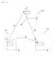
FIG. 2 is a conceptual diagram illustrating a depth image synthesis predicting method using a 3D warphing method according to the preferred embodiment of the invention; -
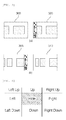
FIGS. 3 to 5 are conceptual diagrams illustrating a method of removing holes in a depth image according to the preferred embodiment of the invention; -
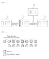
FIG. 6 is a conceptual diagram illustrating a process of applying a depth image according to the preferred embodiment of the invention to a multi-view depth image decoding method; -
FIG. 7 is a block diagram illustrating an internal structure of an encoder according to the preferred embodiment of the invention; -
FIG. 8 is a flowchart sequentially illustrating an encoding method of an encoder according to the preferred embodiment of the invention; -
FIG. 9 is a block diagram illustrating an internal structure of a decoder according to the preferred embodiment of the invention; and -
FIG. 10 is a flowchart sequentially illustrating a decoding method of a decoder according to the preferred embodiment of the invention. - The preferred embodiments of the invention will now be described in detail with reference to the accompanying drawings. Like reference numerals designate like elements throughout the specification. However, in describing the present invention, when the specific description of the related known technology or function departs from the scope of the present invention, the detailed description of the corresponding known technology or function will be omitted. Hereinafter, the preferred embodiments of the present invention will be described, but the technical scope of the present invention is not limited thereto, and various modifications and changes can be made by those skilled in the art without departing from the spirit and scope of the present invention.
- In this invention, a depth image at a specific viewpoint is generated from at least one reference image. Specifically, this invention sequentially executes a down-sampling step of reducing a size of a reference image as a depth image that has a simpler pixel value than a texture image, a step of predicting a depth image at a specific viewpoint from the reference image using a 3D warphing method, and a step of removing, when a hole is generated in the predicted depth image, the hole using the reference image and values of pixels around the hole, thereby generating a depth image that can be viewed at a desired viewpoint. Hereinafter, the preferred embodiments of the invention will be described in detail with reference to the accompanying drawings.
-
FIG. 1 is a flowchart illustrating a depth image generating method according to the preferred embodiment of the invention. Hereinafter, the depth image generating method using the reference image will be described with reference toFIG. 1 . - First, a depth camera is used to photograph a depth image at any viewpoint (S100). The depth image is hereinafter used as a reference image in the preferred embodiments of the invention. In this case, information that is related to a texture image may be obtained using a multi-view camera, and information that is obtained on the basis of a stereo matching method may be applied to the photographed depth image. This stereo matching method enables the depth image to have an accurate depth value. Meanwhile, the stereo matching method is a method in which a three-dimensional image is generated using two-dimensional images that are obtained from spatially different planes. Meanwhile, in the depth image generating method using the reference image, since the reference image can be obtained in advance, Step S100 that has been described above may be omitted.
- Then, the reference image is down-sampled (S105). In general, the reference image has a simpler pixel value than a texture image. Accordingly, down-sampling is preferably applied to the reference image in consideration of encoding, transmission, and decoding processes, which will be performed hereinafter. At the time of down-sampling, a sampling ratio is preferably 1/2 or 1/4, because the corresponding sampling ratio is suitable for keeping an optimal depth value. Meanwhile, the reference image that is transmitted after encoding is up-sampled to have an original size, immediately or during a decoding process.
- Then, the 3D warphing method is used to estimate and generate a depth image in a specific viewing direction from the reference image (S110). Hereinafter, this method is defined as a depth image synthesis predicting method using the 3D warphing method. In general, since the depth image has depth image needed to perform 3D warphing, it is possible to generate a depth image in a specific viewing direction that corresponds to a target without additional information other than camera parameters. In order to generate the depth image in the specific viewing direction, the following
Equations 1 and 2 are used.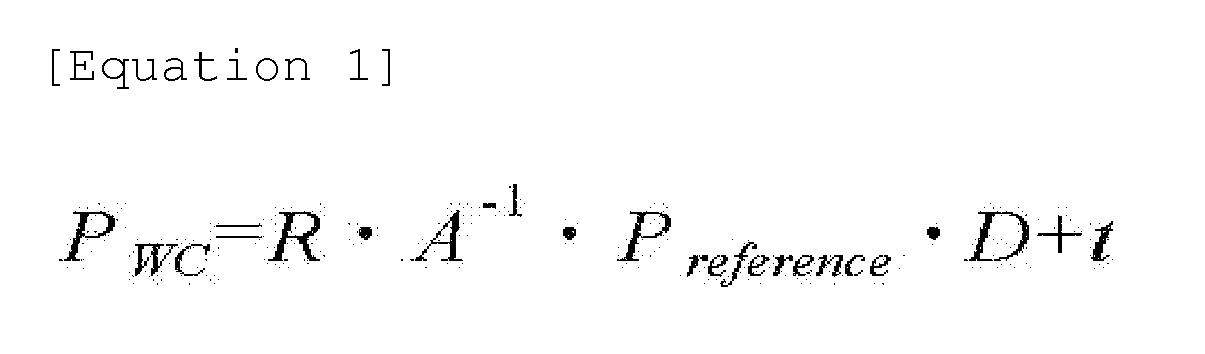

- In
Equations 1 and 2, Pwc, Preference, and Ptarget denote coordinate information, a reference image, and a target image in a three-dimensional space, respectively. In addition, R, A, D, and t denote a rotational variable, a unique variable of a camera, depth information, and a movement variable, respectively. - Hereinafter, the depth image synthesis predicting method will be described in detail with reference to
FIG. 2 . First, positions of the pixel values that exist in areference image 200 as a two-dimensional image are projected onto a three-dimensional space 220 using Equation 1 ((a) ofFIG. 2 ). Then, using Equation 2, the projected position values on the three-dimensional space 220 are reprojected at predetermined positions of atarget image 210 as a two-dimensional image ((b) ofFIG. 2 ). Then, the pixel values of thereference image 200 are transmitted to the pixel positions of thetarget image 210 that are determined to correspond to the pixel positions of the reference image 200 ((c) ofFIG. 2 ). If the above-described processes of (a), (b), and (c) are sequentially executed, it is possible to generate a depth image in a specific viewing direction according to the embodiment of the invention. - Then, the hole that exists in the predicted and generated depth image is removed (S115). In the depth image that is predicted and generated in Step S110, a hole may be generated due to a closed area. Accordingly, the depth image generating method according to the embodiment of the invention further includes a process of removing a hole, after the processes of (a) to (c). The process of removing a hole will be described below with reference to
FIGS. 3 to 5 . - When the depth image that is generated by the processes of (a) to (c) uses a
left viewpoint image 300 as the reference image, large and small holes are generated at the left side of adepth image 305, as shown inFIG. 3A . Meanwhile, when the depth image that is generated by the processes of (a) to (c) uses aright viewpoint image 310 as the reference image, large and small holes are generated at the right side of thedepth image 305, as shown inFIG. 3B . These holes are generated during a process of virtually setting a portion (that is, closed area) that cannot be represented by theleft viewpoint image 300 or theright viewpoint image 310. Accordingly, when the reference image is a single image, it is impossible to calculate values corresponding to the holes. - For this reason, in this invention, an intermediate value of pixel values that are determined as available pixel values among eight pixel values around a hole is adopted, as shown in
FIG. 4 . When the intermediate value is calculated, a median filter may be used. However, when the hole is generated in an area that forms a boundary between the foreground and the background, if the intermediate value is adopted, the boundary may collapse. At this time, the intermediate value is preferably calculated using only pixel values belonging to a specific area among the pixel values around the hole by determining whether the hole belongs to the foreground or the background on the basis of all round values of the hole. - If any viewpoint image is used as the reference image, holes are generated in a portion that is related to any viewpoint image as described in the case of (1). However, for example, when the
left viewpoint image 300 is used as the reference image, if theright viewpoint image 310 is used as another reference image, it is very easy to fill pixel values of the holes that are generated at the left side of thedepth image 305. The reason is because the pixel values of the holes can be predicted from theright viewpoint image 310. Accordingly, the method of removing holes is performed as shown inFIG. 5 . - In a first step, holes are generated at one side of a
depth image 325 that is generated using areference image 320 at the specific viewpoint. Then, in a second step, the holes of thedepth image 325 are removed using areference image 330 at another viewpoint. In this case, when two or more pixel values in the reference image are mapped to a pixel value at one point of the target image at the time of synthesizing images, it is preferable to discriminate between the foreground and the background using the depth values. After the first and second steps are executed, almost all of the holes of thedepth image 325 are removed. However, holes may remain, which are not removed in thedepth image 325. In this case, it is preferable to use the above-described median filter applying method. - If Step S115 is executed, it is possible to generate the depth image in the specific viewing direction according to the embodiment of the invention (S120). The depth image may be used as an additional reference image when images at a viewpoint P and a viewpoint B are encoded, as shown in
FIG. 6 . Accordingly, the depth image ultimately improves encoding efficiency. - Hereinafter, an encoder for encoding a generated depth image, an encoding method using the encoder, a decoder for decoding the depth image, and a decoding method using the decoder will be sequentially described with reference to
FIGS. 1 to 6 . First, the encoder will be described. -
FIG. 7 is a block diagram illustrating an internal structure of an encoder according to the preferred embodiment of the invention. Referring toFIG. 7 , anencoder 700 according to the preferred embodiment of the invention includes a down-sampling unit 702, a depthimage predicting unit 704, ahole removing unit 706, animage prediction block 710, an image T/Q unit 730, and anentropy coding block 740. - The
encoder 700 according to the preferred embodiment of the invention may be implemented by a two-dimensional video encoder in consideration of a simple embodiment structure. However, the invention is not limited thereto, and theencoder 700 may be implemented by a three-dimensional video encoder. In particular, it is preferable that theencoder 700 be implemented by an H.264 encoder in consideration of high data compression efficiency. - The down-
sampling unit 702 performs down-sampling on a reference image in the preferred embodiment of the invention. - The depth
image predicting unit 704 predicts and generates a depth image in a specific viewing direction using a 3D warphing method on the basis of the down-sampled reference image. The detailed description thereof has been given above with reference toEquations 1 and 2 andFIG. 2 and thus is omitted herein. - The
hole removing unit 706 removes holes that exist in the predicted and generated depth image in the preferred embodiment of the invention. The detailed description thereof has been given above with reference toFIGS. 3 to 5 and thus is omitted herein. Meanwhile, in the preferred embodiment of the invention, thehole removing unit 706 may convert the depth image into a frame of a form that is supported by an H.264 encoder. - The
image prediction block 710 performs inter-prediction and intra-prediction in the preferred embodiment of the invention. In this case, in the inter-prediction, block prediction of a depth image frame Fn is performed using a reference image frame Fn-1 that is stored in a buffer after decoding and deblocking filtering. In addition, in the intra-prediction, block prediction is performed using pixel data of a block that is adjacent to a block that is desired to predict in the decoded depth image frame Fn. Similar to the case of the H.264 encoder according to the related art, in the preferred embodiment of the invention, theimage prediction block 710 includes asubtracter 712a, anadder 712b, amotion estimation section 714, amotion compensation unit 716, an intra-frameestimation selection unit 718, anintra-prediction execution unit 720, afilter 722, aninverse transform unit 724, and aninverse quantization unit 726. In this case, themotion estimation section 714 and themotion compensation unit 716 provide blocks having different shapes and sizes, and may be designed to support 1/4 pixel motion estimation, multiple reference frame selection, and multiple bidirectional mode selection. However, themotion estimation section 714 and themotion compensation unit 716 may provide blocks having the same shape and size. Since theimage prediction block 710 andindividual units 712a to 726 that constitute theimage prediction block 710 can be easily embodied by those skilled in the art, the detailed description thereof will be omitted. - In this embodiment, the image T/
Q unit 730 transforms and quantizes an estimation sample that is predicted and obtained by theimage prediction block 710. To do so, the image T/Q unit 730 includes atransform block 732 and aquantization block 734. In this case, thetransform block 732 may be designed to use a separable integer transform (SIT) instead of a discrete cosine transform (DCT) that is mainly used in respects to the video compression standards according to the related art. In this case, a high-speed operation work of thetransform block 732 is enabled and distortion can be prevented from occurring due to a mismatch in an inverse transform, which can be easily embodied by those skilled in the art as described above. Therefore, the detailed description thereof will be omitted herein. - In this embodiment, the
entropy coding block 740 encodes quantized video data according to a predetermined method to generate a bit stream. To do so, theentropy coding block 740 includes arearranging unit 742 and anentropy coding unit 744. In this case, theentropy coding unit 744 may be designed to perform efficient compression using an entropy coding scheme, such as universal variable length coding (UVLC), context adaptive variable length coding (CAVLC), and context adaptive binary arithmetic coding (CABAC). Since theentropy coding unit 744 is a component that is included in the H.264 encoder according to the related art, theentropy coding unit 744 may be easily embodied by those skilled in the art, and thus the detailed description thereof will be omitted herein. - Next, an encoding method of the
encoder 700 will be described.FIG. 8 is a flowchart sequentially illustrating an encoding method of an encoder according to the preferred embodiment of the invention. Hereinafter, the description is given with reference toFIG. 8 . - First, the down-
sampling unit 702 performs down-sampling on the reference image (S800). Then, the depthimage predicting unit 704 predicts and generates a depth image in a specific viewing direction using a 3D warphing method on the basis of the down-sampled reference image (S805) Then, thehole removing unit 706 removes the holes that exist in the predicted and generated depth image (S810). - If the frame Fn of the depth image that is generated in Steps S800 to S810 is input, the
image prediction block 710 and the image T/Q unit 730 encode a transmitted macro block using one of an intra-frame mode and an inter-frame mode (S815). An estimation macro block P is generated even when the inter-frame mode or the intra-frame mode is used (S820). The intra-frameestimation selection unit 718 determines which of the inter-fame mode or the intra-frame mode is used. First, when the intra-frame mode is used, the depth image frame Fn is processed by thetransform block 732 and thequantization block 734 of the image T/Q unit 730. Then, the processed frame Fn is reconfigured by theinverse quantization unit 726 and theinverse transform unit 724 of theimage prediction block 710. As a result, the macro block P is generated. Meanwhile, when the inter-frame mode is used, themotion estimation section 714 of theimage prediction block 710 predicts a motion of the depth image frame Fn on the basis of the depth image frame Fn and at least one reference image frame Fn-1. As a result, themotion compensation unit 716 compensates for the motion of the depth image frame Fn and generates the macro block P. - If the estimation macro block P is generated, the estimation macro block P and the macro block of the depth image frame Fn are input to the subtracter 712a to obtain a difference value macro block Dn (S825). Then, the difference value macro block is IBT-transformed by the
transform block 732, and is quantized in a constant quantization step Qstep in the quantization block 734 (S830). - In the quantized macro block, transform coefficients that are scanned and quantized in a predetermined form (for example, a zigzag form) are sequentially arranged by the rearranging
unit 742 of theentropy coding block 740. Then, a series of arranged transform coefficients are encoded by theentropy coding unit 744 and output in a form of a bit stream (S835). Meanwhile, at this time or hereinafter, theentropy coding unit 744 also transmits a sampling ratio. - Meanwhile, a reconfigured frame uF'n passes through the
filter 722 and is then stored in aspecific buffer 750 so as to be used when another frame is encoded in the future. Thefilter 722 is a deblocking filter that is used to suppress distortion from occurring between macro blocks of the reconfigured frame uF'n. Thefilter 722 is preferably implemented by an adaptive in-loop filter so as to simultaneously achieve subjective quality improvement of video and an increase in compression efficiency. - Next, the decoder will be described.
FIG. 9 is a block diagram illustrating an internal structure of a decoder according to the preferred embodiment of the invention. Referring toFIG. 9 , adecoder 900 according to the preferred embodiment of the invention includes an up-sampling unit 905, anentropy decoding unit 910, arearranging unit 742, aninverse quantization unit 726, aninverse transform unit 724, anadder 712b, amotion compensation unit 716, anintra-prediction execution unit 720, afilter 722, and abuffer 750. - The
decoder 900 according to the preferred embodiment of the invention further includes an up-sampling unit 905 that up-samples a down-sampled image, because the down-sampled image is transmitted. - The up-
sampling unit 905 performs up-sampling on an image that passes through thefilter 722 in the preferred embodiment of the invention. However, in order to perform the above function, the up-sampling unit 905 needs to know a sampling ratio. The sampling ratio is generally transmitted together with the bit stream or transmitted from theencoder 700 hereinafter. However, the invention is not limited thereto, and the sampling ratio may be determined in advance and stored in each of theencoder 700 and thedecoder 900. - In the embodiment of the invention, if the bit stream is input, the
entropy decoding unit 910 reconfigures transform coefficients of the macro blocks on the basis of the bit stream. - The functions of the
rearranging unit 742, theinverse quantization unit 726, theinverse transform unit 724, theadder 712b, themotion compensation unit 716, theintra-prediction execution unit 720, thefilter 722, and thebuffer 750 have been described above with reference toFIG. 7 , and thus the detailed description thereof will be omitted herein. - Next, a decoding method of the
decoder 900 will be described.FIG. 10 is a flowchart sequentially illustrating a decoding method of a decoder according to the preferred embodiment of the invention. Hereinafter, the decoding method will be described with reference toFIG. 10 . - First, if a bit stream is input to the decoder 900 (S1000), the
entropy decoding unit 910 reconfigures transform coefficients of macro blocks on the basis of the bit stream (S1005). The reconfigured transform coefficients are configured in a form of macro blocks in the rearranging unit 742 (S1010). The macro block that is configured in Step S1005 is generated as a difference value macro block Dn by theinverse quantization unit 726 and the inverse transform unit 724 (S1015). - Meanwhile, the estimation macro block P is generated by the
motion compensation unit 716 in accordance with the inter-frame mode or theintra-prediction execution unit 720 in accordance with the intra-frame mode, in consideration of the reference image frame Fn-1 (S1020). The generated estimation macro block P and the difference value macro block Dn generated in Step S1015 are summed by theadder 712b. As a result, the reconfigured frame uF'n is generated (S1025). The reconfigured frame uF'n is filtered by thedeblocking filter 722 and up-sampled by the up-sampling unit 905. As a result, the depth image according to the embodiment of the invention is generated and stored in the buffer 750 (S1030). - Meanwhile, the depth image that is generated by the depth image generating method, the encoder, the encoding method, the decoder, and the decoding method according to the embodiment of the invention is stored in a computer readable recording medium (for example, a CD or a DVD). The three-dimensional video that is generated on the basis of the depth image may be stored the recording medium.
- In this invention, it is possible to implement a device that can form the depth image generated with reference to
FIGS. 1 to 6 . Specifically, the device may include a down-sampling unit that down-samples the reference image, a depth image prediction unit that predicts and generates a depth image in a specific viewing direction using the 3D warphing method on the basis of the down-sampled reference image, and a hole removing unit that removes holes in the predicted and generated depth image. - Although the present invention has been described in connection with the exemplary embodiments of the present invention, it will be apparent to those skilled in the art that various modifications and changes may be made thereto without departing from the scope and spirit of the invention. Therefore, it should be understood that the above embodiments are not limitative, but illustrative in all aspects. The scope of the present invention is defined by the appended claims rather than by the description preceding them, and all changes and modifications that fall within metes and bounds of the claims, or equivalents of such metes and bounds are therefore intended to be embraced by the claims.
- According to the invention, the generated depth image can be applied to a three-dimensional restoration technology or a three-dimensional warphing technology. Encoding of the depth image according to the embodiment of the invention may be used in an image medium (or an image theater), such as a three-dimensional TV or a free viewpoint TV. The depth image or the encoding method of the depth image according to the embodiment of the invention can be used in various broadcasting technologies and thus industrial applicability is high.
Claims (18)
- A depth image generating method comprising:a step (a) of obtaining a depth image at a viewpoint and setting the obtained depth image to a reference image;a step (b) of applying a 3D warphing method to the reference image and predicting and generating a depth image at a specific viewpoint; anda step (c) of removing a hole that exists in the predicted and generated depth image.
- The depth image generating method of claim 1,
wherein, in the step (a), the reference image is down-sampled. - The depth image generating method of claim 1,
wherein the step (b) includes:a step (b1) of projecting positions of pixel values existing in the reference image onto a three-dimensional space;a step (b2) of reprojecting the projected position values on the three-dimensional space at predetermined positions of a target image; anda step (b3) of transmitting the pixel values of the reference image to pixel positions of the target image corresponding to pixel positions of the reference image. - The depth image generating method of claim 1,
wherein, in the step (c), when one reference image exists, an intermediate value of available pixel values among the pixel values around the hole is applied to the hole so as to remove the hole, and when a plurality of reference images exist, a pixel value of a corresponding portion of another reference image is applied to a hole of a depth image that is predicted and generated from a specific reference image so as to remove the hole. - The depth image generating method of claim 4, further comprising:when the hole is not removed from the predicted and generated depth image,a step (c1) of applying an intermediate value of available pixel values among pixel values around the hole to the hole; anda step (c2) of extracting the pixel value applied to the hole and applying the pixel value to the predicted and generated depth image.
- A depth image generating device comprising:a depth image storage unit that obtains a depth image at a viewpoint and stores the obtained depth image as a reference image;a depth image prediction unit that applies a 3D warphing method to the reference image and predicts and generates a depth image at a specific viewpoint; anda hole removing unit that removes a hole that exists in the depth image predicted and generated by the depth image prediction unit.
- The depth image generating device of claim 6, further comprising:a down-sampling unit that down-samples the reference image stored in the depth image storage unit.
- The depth image generating device of claim 6,
wherein the depth image prediction unit projects positions of pixel values existing in the reference image onto a three-dimensional space, reprojects the projected position values on the three-dimensional space at predetermined positions of a target image, and transmits the pixel values of the reference image to pixel positions of the target image corresponding to pixel positions of the reference image, such that the depth image at the specific viewpoint is predicted and generated. - The depth image generating device of claim 6,
wherein, when one reference image exists, the hole removing unit applies an intermediate value of available pixel values among pixel values around the hole to the hole so as to remove the hole, and when a plurality of reference images exist, the hole removing unit applies a pixel value of a corresponding portion of another reference image to a hole of a depth image that is predicted and generated from a specific reference image so as to remove the hole. - The depth image generating device of claim 9,
wherein, when the hole is not removed from the predicted and generated depth image, the hole removing unit applies an intermediate value of available pixel values among pixel values around the hole to the hole, extracts the pixel value applied to the hole, and applies the pixel value to the predicted and generated depth image, such that the hole is removed. - An encoding method using a depth image at a specific viewpoint, the depth image being generated using the following steps:a step (a) of obtaining a depth image at a viewpoint and setting the obtained depth image to a reference image;a step (b) of applying a 3D warphing method to the reference image and predicting and generating the depth image at a specific viewpoint; anda step (c) of removing a hole that exists in the predicted and generated depth image.
- The encoding method of claim 11,
wherein the step (b) includes:a step (b1) of projecting positions of pixel values existing in the reference image onto a three-dimensional space;a step (b2) of reprojecting the projected position values on the three-dimensional space at predetermined positions of a target image; anda step (b3) of transmitting the pixel values of the reference image to pixel positions of the target image corresponding to pixel positions of the reference image. - The encoding method of claim 11,
wherein, in the step (c), when one reference image exists, an intermediate value of available pixel values among pixel values around the hole is applied to the hole so as to remove the hole, and when a plurality of reference images exist, a pixel value of a corresponding portion of another reference image is applied to a hole of a depth image that is predicted and generated from a specific reference image so as to remove the hole. - An encoder comprising:an image prediction unit that performs inter-prediction and intra-prediction;an image T/Q unit that transforms and quantizes a prediction sample that is obtained by the image prediction unit;an entropy coding unit that encodes image data quantized by the image T/Q unit; anda depth image generating unit that generates a depth image at a specific viewpoint by the image prediction unit,wherein the depth image generating unit includes:a depth image prediction unit that applies a 3D warphing method to a reference image using a depth image at a viewpoint as the reference image and predicts and generates a depth image at a specific viewpoint; anda hole removing unit that removes a hole that exists in the depth image predicted and generated by the depth image prediction unit.
- The encoder of claim 14,
wherein the depth image prediction unit projects positions of pixel values existing in the reference image onto a three-dimensional space, reprojects the projected position values on the three-dimensional space at predetermined positions of a target image, and transmits the pixel values of the reference image to pixel positions of the target image corresponding to pixel positions of the reference image, such that the depth image at the specific viewpoint is predicted and generated. - The depth image generating device of claim 14,
wherein, when one reference image exists, the hole removing unit applies an intermediate value of available pixel values among pixel values around the hole to the hole so as to remove the hole, and when a plurality of reference images exist, the hole removing unit applies a pixel value of a corresponding portion of another reference image to a hole of a depth image that is predicted and generated from a specific reference image so as to remove the hole, such that the depth image is generated. - A decoding method that decodes the image encoded by the method of any one of claims 11 to 13.
- A decoder that decodes the image encoded by the method of any one of claims 11 to 13.
Applications Claiming Priority (1)
| Application Number | Priority Date | Filing Date | Title |
|---|---|---|---|
| KR1020070105592A KR100918862B1 (en) | 2007-10-19 | 2007-10-19 | Method and device for generating depth image using reference image, and method for encoding or decoding the said depth image, and encoder or decoder for the same, and the recording media storing the image generating the said method |
Publications (2)
| Publication Number | Publication Date |
|---|---|
| EP2059053A2 true EP2059053A2 (en) | 2009-05-13 |
| EP2059053A3 EP2059053A3 (en) | 2011-09-07 |
Family
ID=40386246
Family Applications (1)
| Application Number | Title | Priority Date | Filing Date |
|---|---|---|---|
| EP20080105614 Withdrawn EP2059053A3 (en) | 2007-10-19 | 2008-10-20 | Method and device for generating depth image using reference image, method for encoding/decoding depth image, and encoder or decoder for the same |
Country Status (4)
| Country | Link |
|---|---|
| US (1) | US20090103616A1 (en) |
| EP (1) | EP2059053A3 (en) |
| JP (1) | JP2009105894A (en) |
| KR (1) | KR100918862B1 (en) |
Cited By (7)
| Publication number | Priority date | Publication date | Assignee | Title |
|---|---|---|---|---|
| WO2012090181A1 (en) * | 2010-12-29 | 2012-07-05 | Nokia Corporation | Depth map coding |
| CN103081480A (en) * | 2010-09-03 | 2013-05-01 | 索尼公司 | Image processing device and method |
| CN103081479A (en) * | 2010-09-03 | 2013-05-01 | 索尼公司 | Encoding device, encoding method, decoding device, and decoding method |
| CN103124361A (en) * | 2011-11-21 | 2013-05-29 | 浙江大学 | Video processing method, video code stream and video processing device |
| EP2592839A4 (en) * | 2010-09-03 | 2014-08-06 | Sony Corp | DEVICE AND ENCODING METHOD, AND DEVICE, AND DECODING METHOD |
| CN105979240A (en) * | 2010-09-03 | 2016-09-28 | 索尼公司 | Encoding device and encoding method, as well as decoding device and decoding method |
| CN103124361B (en) * | 2011-11-21 | 2016-12-14 | 浙江大学 | A kind of method for processing video frequency, video code flow and video process apparatus |
Families Citing this family (54)
| Publication number | Priority date | Publication date | Assignee | Title |
|---|---|---|---|---|
| BR122018004903B1 (en) | 2007-04-12 | 2019-10-29 | Dolby Int Ab | video coding and decoding tiling |
| US8774512B2 (en) * | 2009-02-11 | 2014-07-08 | Thomson Licensing | Filling holes in depth maps |
| BRPI1013339B1 (en) * | 2009-02-19 | 2021-09-21 | Interdigital Madison Patent Holdings | METHOD AND APPARATUS FOR ENCODING VIDEO, METHOD AND APPARATUS FOR DECODING VIDEO, VIDEO SIGNAL FORMATTED TO INCLUDE INFORMATION AND MEDIA READABLE BY PROCESSOR |
| KR101054875B1 (en) * | 2009-08-20 | 2011-08-05 | 광주과학기술원 | Bidirectional prediction method and apparatus for encoding depth image |
| KR101113526B1 (en) * | 2009-11-26 | 2012-02-29 | 이근상 | Rotating Feed Device of Bar and Heat Treatment Equipment of Bar Using the That |
| KR101407818B1 (en) * | 2009-12-08 | 2014-06-17 | 한국전자통신연구원 | Apparatus and method for extracting depth image and texture image |
| KR101377325B1 (en) * | 2009-12-21 | 2014-03-25 | 한국전자통신연구원 | Stereoscopic image, multi-view image and depth image acquisition appratus and its control method |
| KR101828096B1 (en) | 2010-01-29 | 2018-02-09 | 톰슨 라이센싱 | Block-based interleaving |
| KR101647408B1 (en) | 2010-02-03 | 2016-08-10 | 삼성전자주식회사 | Apparatus and method for image processing |
| KR101289269B1 (en) * | 2010-03-23 | 2013-07-24 | 한국전자통신연구원 | An apparatus and method for displaying image data in image system |
| KR101598855B1 (en) | 2010-05-11 | 2016-03-14 | 삼성전자주식회사 | Apparatus and Method for 3D video coding |
| KR20110135786A (en) * | 2010-06-11 | 2011-12-19 | 삼성전자주식회사 | 3D video encoding / decoding apparatus and method using depth transition data |
| EP2400768A3 (en) * | 2010-06-25 | 2014-12-31 | Samsung Electronics Co., Ltd. | Method, apparatus and computer-readable medium for coding and decoding depth image using color image |
| KR101702948B1 (en) * | 2010-07-20 | 2017-02-06 | 삼성전자주식회사 | Rate-Distortion Optimization Apparatus and Method for depth-image encoding |
| KR20120016980A (en) | 2010-08-17 | 2012-02-27 | 한국전자통신연구원 | Image encoding method and apparatus, and decoding method and apparatus |
| JP4964355B2 (en) * | 2010-09-30 | 2012-06-27 | パナソニック株式会社 | Stereoscopic video encoding apparatus, stereoscopic video imaging apparatus, and stereoscopic video encoding method |
| US9865083B2 (en) | 2010-11-03 | 2018-01-09 | Industrial Technology Research Institute | Apparatus and method for inpainting three-dimensional stereoscopic image |
| TWI492186B (en) * | 2010-11-03 | 2015-07-11 | Ind Tech Res Inst | Apparatus and method for inpainting three-dimensional stereoscopic image |
| KR101764424B1 (en) * | 2010-11-08 | 2017-08-14 | 삼성전자주식회사 | Method and apparatus for searching of image data |
| JP5468526B2 (en) | 2010-11-25 | 2014-04-09 | 株式会社東芝 | Image processing apparatus and image processing method |
| US20120176536A1 (en) * | 2011-01-12 | 2012-07-12 | Avi Levy | Adaptive Frame Rate Conversion |
| US9661301B2 (en) * | 2011-02-18 | 2017-05-23 | Sony Corporation | Image processing device and image processing method |
| WO2012147621A1 (en) * | 2011-04-28 | 2012-11-01 | ソニー株式会社 | Encoding device and encoding method, and decoding device and decoding method |
| JP5749595B2 (en) * | 2011-07-27 | 2015-07-15 | 日本電信電話株式会社 | Image transmission method, image transmission apparatus, image reception apparatus, and image reception program |
| KR101276346B1 (en) * | 2011-10-31 | 2013-06-18 | 전자부품연구원 | Method and apparatus for rotating depth map |
| KR101332021B1 (en) * | 2011-10-31 | 2013-11-25 | 전자부품연구원 | Method and apparatus for rotating depth map |
| WO2013068491A1 (en) | 2011-11-11 | 2013-05-16 | Fraunhofer-Gesellschaft zur Förderung der angewandten Forschung e.V. | Multi-view coding with exploitation of renderable portions |
| BR112014011425B1 (en) | 2011-11-11 | 2022-08-23 | GE Video Compression, LLC. | EFFICIENT MULTI-VIEW CODING USING DEPTH ESTIMATING AND MAP UPDATE |
| EP3657796A1 (en) | 2011-11-11 | 2020-05-27 | GE Video Compression, LLC | Efficient multi-view coding using depth-map estimate for a dependent view |
| EP2777256B1 (en) | 2011-11-11 | 2017-03-29 | GE Video Compression, LLC | Multi-view coding with effective handling of renderable portions |
| WO2013072484A1 (en) | 2011-11-18 | 2013-05-23 | Fraunhofer-Gesellschaft zur Förderung der angewandten Forschung e.V. | Multi-view coding with efficient residual handling |
| KR20130073459A (en) * | 2011-12-23 | 2013-07-03 | 삼성전자주식회사 | Method and apparatus for generating multi-view |
| KR101319260B1 (en) * | 2012-02-01 | 2013-10-18 | (주)리얼디스퀘어 | Apparatus and Method for image restoration, stereo-scopic image conversion apparatus and method usig that |
| WO2013115463A1 (en) * | 2012-02-01 | 2013-08-08 | 에스케이플래닛 주식회사 | Device and method for processing images |
| CN103247027B (en) * | 2012-02-13 | 2016-03-30 | 联想(北京)有限公司 | Image processing method and electric terminal |
| KR20140133770A (en) * | 2012-02-23 | 2014-11-20 | 가부시키가이샤 스퀘어.에닉스.홀딩스 | Moving image distribution server, moving image playback apparatus, control method, program, and recording medium |
| KR20150003406A (en) | 2012-04-12 | 2015-01-08 | 가부시키가이샤 스퀘어.에닉스.홀딩스 | Moving image distribution server, moving image reproduction apparatus, control method, recording medium, and moving image distribution system |
| US20150117514A1 (en) * | 2012-04-23 | 2015-04-30 | Samsung Electronics Co., Ltd. | Three-dimensional video encoding method using slice header and method therefor, and three-dimensional video decoding method and device therefor |
| KR101648094B1 (en) * | 2012-09-25 | 2016-08-12 | 니폰 덴신 덴와 가부시끼가이샤 | Image encoding method, image decoding method, image encoding device, image decoding device, image encoding program, image decoding program, and recording medium |
| CN103716641B (en) | 2012-09-29 | 2018-11-09 | 浙江大学 | Prognostic chart picture generation method and device |
| EP4593395A3 (en) | 2012-10-01 | 2025-10-01 | GE Video Compression, LLC | Scalable video coding using inter-layer prediction contribution to enhancement layer prediction |
| JP6150277B2 (en) * | 2013-01-07 | 2017-06-21 | 国立研究開発法人情報通信研究機構 | Stereoscopic video encoding apparatus, stereoscopic video decoding apparatus, stereoscopic video encoding method, stereoscopic video decoding method, stereoscopic video encoding program, and stereoscopic video decoding program |
| CN103067716B (en) * | 2013-01-10 | 2016-06-29 | 华为技术有限公司 | The decoding method of depth image and coding and decoding device |
| CN103067715B (en) | 2013-01-10 | 2016-12-28 | 华为技术有限公司 | The decoding method of depth image and coding and decoding device |
| CN104301700B (en) * | 2013-07-20 | 2017-12-01 | 浙江大学 | Image block boundaries location determining method and device |
| KR102158390B1 (en) * | 2013-10-22 | 2020-09-22 | 삼성전자주식회사 | Method and apparatus for image processing |
| KR101561525B1 (en) * | 2013-12-30 | 2015-10-20 | 재단법인대구경북과학기술원 | Device and method for generating stereo depth images |
| KR101565488B1 (en) | 2014-03-04 | 2015-11-04 | 서울과학기술대학교 산학협력단 | The designs of service scenarios and transport networks for implementing free viewpoint video |
| KR102156410B1 (en) | 2014-04-14 | 2020-09-15 | 삼성전자주식회사 | Apparatus and method for processing image considering motion of object |
| US10659750B2 (en) * | 2014-07-23 | 2020-05-19 | Apple Inc. | Method and system for presenting at least part of an image of a real object in a view of a real environment, and method and system for selecting a subset of a plurality of images |
| KR20160147448A (en) | 2015-06-15 | 2016-12-23 | 한국전자통신연구원 | Depth map coding method using color-mesh-based sampling and depth map reconstruction method using the color and mesh information |
| KR102252298B1 (en) * | 2016-10-21 | 2021-05-14 | 삼성전자주식회사 | Method and apparatus for recognizing facial expression |
| CN109600600B (en) * | 2018-10-31 | 2020-11-03 | 万维科研有限公司 | Encoder, encoding method, and storage method and format of three-layer expression relating to depth map conversion |
| EP3748395B1 (en) * | 2019-06-06 | 2023-01-04 | Infineon Technologies AG | Method and apparatus for compensating stray light caused by an object in a scene that is sensed by a time-of-flight camera |
Family Cites Families (26)
| Publication number | Priority date | Publication date | Assignee | Title |
|---|---|---|---|---|
| JP3231618B2 (en) * | 1996-04-23 | 2001-11-26 | 日本電気株式会社 | 3D image encoding / decoding system |
| US7102633B2 (en) * | 1998-05-27 | 2006-09-05 | In-Three, Inc. | Method for conforming objects to a common depth perspective for converting two-dimensional images into three-dimensional images |
| JP3776595B2 (en) * | 1998-07-03 | 2006-05-17 | 日本放送協会 | Multi-viewpoint image compression encoding apparatus and decompression decoding apparatus |
| US7583270B2 (en) * | 1999-03-02 | 2009-09-01 | Sony Corporation | Image processing apparatus |
| US7236622B2 (en) * | 1999-08-25 | 2007-06-26 | Eastman Kodak Company | Method for forming a depth image |
| US20020015103A1 (en) * | 2000-07-25 | 2002-02-07 | Zhimin Shi | System and method of capturing and processing digital images with depth channel |
| US20020138264A1 (en) * | 2001-03-21 | 2002-09-26 | International Business Machines Corporation | Apparatus to convey depth information in graphical images and method therefor |
| WO2003005727A1 (en) * | 2001-07-06 | 2003-01-16 | Koninklijke Philips Electronics N.V. | Methods of and units for motion or depth estimation and image processing apparatus provided with such motion estimation unit |
| KR100433625B1 (en) * | 2001-11-17 | 2004-06-02 | 학교법인 포항공과대학교 | Apparatus for reconstructing multiview image using stereo image and depth map |
| KR100446635B1 (en) * | 2001-11-27 | 2004-09-04 | 삼성전자주식회사 | Apparatus and method for depth image-based representation of 3-dimensional object |
| US6956566B2 (en) * | 2002-05-23 | 2005-10-18 | Hewlett-Packard Development Company, L.P. | Streaming of images with depth for three-dimensional graphics |
| US7224355B2 (en) * | 2002-10-23 | 2007-05-29 | Koninklijke Philips Electronics N.V. | Method for post-processing a 3D digital video signal |
| AU2002952874A0 (en) * | 2002-11-25 | 2002-12-12 | Dynamic Digital Depth Research Pty Ltd | 3D image synthesis from depth encoded source view |
| DE60234040D1 (en) * | 2002-12-13 | 2009-11-26 | Schlumberger Holdings | Method and apparatus for improved depth adjustment of wellbore images or sample images |
| CN1723476A (en) * | 2003-01-06 | 2006-01-18 | 皇家飞利浦电子股份有限公司 | Method and apparatus for depth sorting of digital images |
| US7321669B2 (en) * | 2003-07-10 | 2008-01-22 | Sarnoff Corporation | Method and apparatus for refining target position and size estimates using image and depth data |
| ITRM20030345A1 (en) * | 2003-07-15 | 2005-01-16 | St Microelectronics Srl | METHOD TO FIND A DEPTH MAP |
| US20050036702A1 (en) * | 2003-08-12 | 2005-02-17 | Xiaoli Yang | System and method to enhance depth of field of digital image from consecutive image taken at different focus |
| KR100519779B1 (en) * | 2004-02-10 | 2005-10-07 | 삼성전자주식회사 | Method and apparatus for high speed visualization of depth image-based 3D graphic data |
| JP2006074474A (en) * | 2004-09-02 | 2006-03-16 | Toshiba Corp | Moving picture coding apparatus, moving picture coding method, and moving picture coding program |
| KR100624457B1 (en) * | 2005-01-08 | 2006-09-19 | 삼성전자주식회사 | Depth-Image Based Modeling Method and Apparatus |
| US8009871B2 (en) * | 2005-02-08 | 2011-08-30 | Microsoft Corporation | Method and system to segment depth images and to detect shapes in three-dimensionally acquired data |
| KR100707206B1 (en) * | 2005-04-11 | 2007-04-13 | 삼성전자주식회사 | Depth Image-based Representation method for 3D objects, Modeling method and apparatus using it, and Rendering method and apparatus using the same |
| KR100748719B1 (en) * | 2005-07-14 | 2007-08-13 | 연세대학교 산학협력단 | 3D modeling device using multi-stereo camera and method thereof |
| JP4414379B2 (en) * | 2005-07-28 | 2010-02-10 | 日本電信電話株式会社 | Video encoding method, video decoding method, video encoding program, video decoding program, and computer-readable recording medium on which these programs are recorded |
| BRPI0716814A2 (en) * | 2006-09-20 | 2013-11-05 | Nippon Telegraph & Telephone | IMAGE CODING METHOD, AND DECODING METHOD, APPARATUS FOR THIS, IMAGE DECODING APPARATUS, PROGRAMS FOR THIS, AND STORAGE MEDIA TO STORE PROGRAMS |
-
2007
- 2007-10-19 KR KR1020070105592A patent/KR100918862B1/en not_active Expired - Fee Related
-
2008
- 2008-10-18 US US12/253,959 patent/US20090103616A1/en not_active Abandoned
- 2008-10-20 EP EP20080105614 patent/EP2059053A3/en not_active Withdrawn
- 2008-10-20 JP JP2008269484A patent/JP2009105894A/en active Pending
Non-Patent Citations (6)
| Title |
|---|
| CHEON LEE ET AL: "View Synthesis Tools for 3D Video", 86. MPEG MEETING; 13-10-2008 - 17-10-2008; BUSAN; (MOTION PICTURE EXPERT GROUP OR ISO/IEC JTC1/SC29/WG11),, 9 October 2008 (2008-10-09), XP030044448, * |
| FEHN C: "Depth-image-based rendering (DIBR), compression, and transmission for a new approach on 3D-TV", PROCEEDINGS OF SPIE, THE INTERNATIONAL SOCIETY FOR OPTICAL ENGINEERING SPIE, USA, vol. 5291, 31 May 2004 (2004-05-31), pages 93-104, XP002444222, ISSN: 0277-786X, DOI: 10.1117/12.524762 * |
| HAI TAO ET AL: "A global matching framework for stereo computation", PROCEEDINGS OF THE EIGHT IEEE INTERNATIONAL CONFERENCE ON COMPUTER VISION. (ICCV). VANCOUVER, BRITISH COLUMBIA, CANADA, JULY 7 - 14, 2001; [INTERNATIONAL CONFERENCE ON COMPUTER VISION], LOS ALAMITOS, CA : IEEE COMP. SOC, US, vol. 1, 7 July 2001 (2001-07-07), pages 532-539, XP010554026, ISBN: 978-0-7695-1143-6 * |
| MARK W R ET AL: "Efficient Reconstruction Techniques for Post-Rendering 3D Image Warping", INSIDE THE FFT BLACK BOX. SERIAL AND PARALLEL FAST FOURIERTRANSFORM ALGORITHMS, no. TR98-011, 21 March 1998 (1998-03-21), pages 1-14, XP002312619, ISBN: 978-0-8493-0270-6 * |
| MARK W R ET AL: "POST-RENDERING 3D WARPING", PROCEEDINGS OF 1997 SYMPOSIUM ON INTERACTIVE 3 D GRAPHICS 27-30 APRIL 1997 PROVIDENCE, RI, USA; [PROCEEDINGS OF THE SYMPOSIUM ON INTERACTIVE 3D GRAPHICS], PROCEEDINGS 1997 SYMPOSIUM ON INTERACTIVE 3D GRAPHICS ACM NEW YORK, NY, USA, 27 April 1997 (1997-04-27), pages 7-16, XP000725355, DOI: 10.1145/253284.253292 ISBN: 978-0-89791-884-8 * |
| POOJA VERLANI ET AL: "Depth Images: Representations and Real-Time Rendering", 3D DATA PROCESSING, VISUALIZATION, AND TRANSMISSION, THIRD INTERNATION AL SYMPOSIUM ON, IEEE, PI, 1 June 2006 (2006-06-01), pages 962-969, XP031079040, ISBN: 978-0-7695-2825-0 * |
Cited By (13)
| Publication number | Priority date | Publication date | Assignee | Title |
|---|---|---|---|---|
| CN105979240A (en) * | 2010-09-03 | 2016-09-28 | 索尼公司 | Encoding device and encoding method, as well as decoding device and decoding method |
| CN103081480A (en) * | 2010-09-03 | 2013-05-01 | 索尼公司 | Image processing device and method |
| CN103081479A (en) * | 2010-09-03 | 2013-05-01 | 索尼公司 | Encoding device, encoding method, decoding device, and decoding method |
| EP2613537A4 (en) * | 2010-09-03 | 2014-08-06 | Sony Corp | DEVICE AND ENCODING METHOD, AND DEVICE, AND DECODING METHOD |
| EP2592839A4 (en) * | 2010-09-03 | 2014-08-06 | Sony Corp | DEVICE AND ENCODING METHOD, AND DEVICE, AND DECODING METHOD |
| EP2613538A4 (en) * | 2010-09-03 | 2014-08-13 | Sony Corp | IMAGE PROCESSING DEVICE AND METHOD |
| US9338430B2 (en) | 2010-09-03 | 2016-05-10 | Sony Corporation | Encoding device, encoding method, decoding device, and decoding method |
| US9762884B2 (en) | 2010-09-03 | 2017-09-12 | Sony Corporation | Encoding device, encoding method, decoding device, and decoding method for encoding multiple viewpoints for compatibility with existing mode allowing fewer viewpoints |
| CN105979240B (en) * | 2010-09-03 | 2018-06-05 | 索尼公司 | Code device and coding method and decoding apparatus and coding/decoding method |
| US9398313B2 (en) | 2010-12-29 | 2016-07-19 | Nokia Technologies Oy | Depth map coding |
| WO2012090181A1 (en) * | 2010-12-29 | 2012-07-05 | Nokia Corporation | Depth map coding |
| CN103124361A (en) * | 2011-11-21 | 2013-05-29 | 浙江大学 | Video processing method, video code stream and video processing device |
| CN103124361B (en) * | 2011-11-21 | 2016-12-14 | 浙江大学 | A kind of method for processing video frequency, video code flow and video process apparatus |
Also Published As
| Publication number | Publication date |
|---|---|
| EP2059053A3 (en) | 2011-09-07 |
| KR20090040032A (en) | 2009-04-23 |
| US20090103616A1 (en) | 2009-04-23 |
| JP2009105894A (en) | 2009-05-14 |
| KR100918862B1 (en) | 2009-09-28 |
Similar Documents
| Publication | Publication Date | Title |
|---|---|---|
| EP2059053A2 (en) | Method and device for generating depth image using reference image, method for encoding/decoding depth image, and encoder or decoder for the same | |
| Sikora | Trends and perspectives in image and video coding | |
| EP3669333B1 (en) | Sequential encoding and decoding of volymetric video | |
| CN109691110B (en) | Encoding/decoding method and device for synchronous multi-viewpoint video using spatial layout information | |
| CN101822068B (en) | Method and device for processing depth-map | |
| JP6356286B2 (en) | Multi-view signal codec | |
| TWI685679B (en) | Methods for full parallax compressed light field 3d imaging systems | |
| US20160357147A1 (en) | Methods and Apparatus for Full Parallax Light Field Display Systems | |
| KR20100008649A (en) | Method and device for generating depth image using reference image, and method for encoding or decoding the said depth image, and encoder or decoder for the same, and the recording media storing the image generating the said method | |
| CN101990103B (en) | Method and device for multi-view video coding | |
| HUE026534T2 (en) | Hybrid video encoding to support intermediate view synthesis | |
| WO2006080739A1 (en) | Method and apparatus for encoding and decoding multi-view video using image stitching | |
| KR20100008677A (en) | Device and method for estimating death map, method for making intermediate view and encoding multi-view using the same | |
| JP2024012332A (en) | Multi-view video decoding method and apparatus, and image processing method and apparatus | |
| JP4616564B2 (en) | Video encoding / decoding device and method using digital watermarking | |
| Dricot et al. | Integral images compression scheme based on view extraction | |
| CN113545060B (en) | Empty tile encoding in video encoding | |
| CN101243692B (en) | Method and device for encoding multi-view video | |
| KR101348276B1 (en) | Method and apparatus for encoding multi-view moving pictures | |
| KR100775871B1 (en) | Method and apparatus for encoding and decoding multi-view video images using image stitching | |
| KR100656783B1 (en) | Binocular stereoscopic image transmission device and method thereof, and Binocular stereoscopic image rendering device and method using same | |
| Kim et al. | Edge-preserving directional regularization technique for disparity estimation of stereoscopic images | |
| TWI507020B (en) | Depth-based three-dimensional image processing method | |
| CN111357292B (en) | Method for encoding and decoding a data stream representing omnidirectional video | |
| KR20260025049A (en) | Video Encoding Apparatus, Three-Dimensional Broadcast Transmission Apparatus and Method Including the Same |
Legal Events
| Date | Code | Title | Description |
|---|---|---|---|
| PUAI | Public reference made under article 153(3) epc to a published international application that has entered the european phase |
Free format text: ORIGINAL CODE: 0009012 |
|
| AK | Designated contracting states |
Kind code of ref document: A2 Designated state(s): AT BE BG CH CY CZ DE DK EE ES FI FR GB GR HR HU IE IS IT LI LT LU LV MC MT NL NO PL PT RO SE SI SK TR |
|
| AX | Request for extension of the european patent |
Extension state: AL BA MK RS |
|
| PUAL | Search report despatched |
Free format text: ORIGINAL CODE: 0009013 |
|
| AK | Designated contracting states |
Kind code of ref document: A3 Designated state(s): AT BE BG CH CY CZ DE DK EE ES FI FR GB GR HR HU IE IS IT LI LT LU LV MC MT NL NO PL PT RO SE SI SK TR |
|
| AX | Request for extension of the european patent |
Extension state: AL BA MK RS |
|
| RIC1 | Information provided on ipc code assigned before grant |
Ipc: G06T 3/00 20060101ALI20110804BHEP Ipc: H04N 7/46 20060101ALI20110804BHEP Ipc: H04N 7/50 20060101ALI20110804BHEP Ipc: H04N 7/26 20060101AFI20110804BHEP |
|
| 17P | Request for examination filed |
Effective date: 20120301 |
|
| AKX | Designation fees paid |
Designated state(s): DE FR GB |
|
| STAA | Information on the status of an ep patent application or granted ep patent |
Free format text: STATUS: THE APPLICATION IS DEEMED TO BE WITHDRAWN |
|
| 18D | Application deemed to be withdrawn |
Effective date: 20140501 |