EP2058920A2 - Vehicle audio system power supply - Google Patents
Vehicle audio system power supply Download PDFInfo
- Publication number
- EP2058920A2 EP2058920A2 EP20080167492 EP08167492A EP2058920A2 EP 2058920 A2 EP2058920 A2 EP 2058920A2 EP 20080167492 EP20080167492 EP 20080167492 EP 08167492 A EP08167492 A EP 08167492A EP 2058920 A2 EP2058920 A2 EP 2058920A2
- Authority
- EP
- European Patent Office
- Prior art keywords
- power
- audio system
- control unit
- power supply
- storage battery
- Prior art date
- Legal status (The legal status is an assumption and is not a legal conclusion. Google has not performed a legal analysis and makes no representation as to the accuracy of the status listed.)
- Pending
Links
- 239000003990 capacitor Substances 0.000 claims description 10
- 239000007858 starting material Substances 0.000 claims description 7
- 230000003466 anti-cipated effect Effects 0.000 claims 2
- 230000008878 coupling Effects 0.000 claims 2
- 238000010168 coupling process Methods 0.000 claims 2
- 238000005859 coupling reaction Methods 0.000 claims 2
- 230000003213 activating effect Effects 0.000 claims 1
- 230000001105 regulatory effect Effects 0.000 abstract description 3
- 230000006870 function Effects 0.000 description 7
- 238000010586 diagram Methods 0.000 description 4
- 230000017525 heat dissipation Effects 0.000 description 2
- 230000007704 transition Effects 0.000 description 2
- 230000004913 activation Effects 0.000 description 1
- 230000008859 change Effects 0.000 description 1
- 238000007599 discharging Methods 0.000 description 1
- 238000001914 filtration Methods 0.000 description 1
- 230000004048 modification Effects 0.000 description 1
- 238000012986 modification Methods 0.000 description 1
Images

Classifications
-
- H—ELECTRICITY
- H02—GENERATION; CONVERSION OR DISTRIBUTION OF ELECTRIC POWER
- H02M—APPARATUS FOR CONVERSION BETWEEN AC AND AC, BETWEEN AC AND DC, OR BETWEEN DC AND DC, AND FOR USE WITH MAINS OR SIMILAR POWER SUPPLY SYSTEMS; CONVERSION OF DC OR AC INPUT POWER INTO SURGE OUTPUT POWER; CONTROL OR REGULATION THEREOF
- H02M3/00—Conversion of DC power input into DC power output
- H02M3/02—Conversion of DC power input into DC power output without intermediate conversion into AC
- H02M3/04—Conversion of DC power input into DC power output without intermediate conversion into AC by static converters
- H02M3/10—Conversion of DC power input into DC power output without intermediate conversion into AC by static converters using discharge tubes with control electrode or semiconductor devices with control electrode
- H02M3/145—Conversion of DC power input into DC power output without intermediate conversion into AC by static converters using discharge tubes with control electrode or semiconductor devices with control electrode using devices of a triode or transistor type requiring continuous application of a control signal
- H02M3/155—Conversion of DC power input into DC power output without intermediate conversion into AC by static converters using discharge tubes with control electrode or semiconductor devices with control electrode using devices of a triode or transistor type requiring continuous application of a control signal using semiconductor devices only
-
- B—PERFORMING OPERATIONS; TRANSPORTING
- B60—VEHICLES IN GENERAL
- B60R—VEHICLES, VEHICLE FITTINGS, OR VEHICLE PARTS, NOT OTHERWISE PROVIDED FOR
- B60R16/00—Electric or fluid circuits specially adapted for vehicles and not otherwise provided for; Arrangement of elements of electric or fluid circuits specially adapted for vehicles and not otherwise provided for
- B60R16/02—Electric or fluid circuits specially adapted for vehicles and not otherwise provided for; Arrangement of elements of electric or fluid circuits specially adapted for vehicles and not otherwise provided for electric constitutive elements
- B60R16/03—Electric or fluid circuits specially adapted for vehicles and not otherwise provided for; Arrangement of elements of electric or fluid circuits specially adapted for vehicles and not otherwise provided for electric constitutive elements for supply of electrical power to vehicle subsystems or for
-
- H—ELECTRICITY
- H02—GENERATION; CONVERSION OR DISTRIBUTION OF ELECTRIC POWER
- H02M—APPARATUS FOR CONVERSION BETWEEN AC AND AC, BETWEEN AC AND DC, OR BETWEEN DC AND DC, AND FOR USE WITH MAINS OR SIMILAR POWER SUPPLY SYSTEMS; CONVERSION OF DC OR AC INPUT POWER INTO SURGE OUTPUT POWER; CONTROL OR REGULATION THEREOF
- H02M1/00—Details of apparatus for conversion
- H02M1/0083—Converters characterised by their input or output configuration
- H02M1/009—Converters characterised by their input or output configuration having two or more independently controlled outputs
Definitions
- the present invention relates to a vehicle audio system, and more particularly to a power supply circuit therefor.
- the audio system in a motor vehicle is subject to various power fluctuations and irregularities that have the potential to damage the system circuitry and/or cause undesired system operation.
- the system must be protected from reverse voltages that occur when the battery cables are incorrectly installed. And power fluctuations that produce audible loudspeaker sounds can occur with little or no warning. Accordingly, what is needed is a power supply arrangement that protects the audio system and eliminates undesired system operation.
- the present invention is directed to an improved power supply circuit for an audio system including a power amplifier that operates at full battery voltage and a control unit that operates at a lower regulated voltage.
- Battery voltage is supplied to the control unit voltage regulator through a series diode and to the power amplifier through a normally-off series power-FET.
- the control unit turns on the series power-FET to permit operation of the power amplifier. If the control unit detects a sudden voltage drop or an engine crank signal, it prevents audible loudspeaker sounds by immediately turning off the series power-FET and issuing a shut-down command to the power amplifier. If the battery voltage is reversed, the series diode isolates the control unit, and the series power-FET remains off.
- FIG. 1 is a diagram of a vehicle electrical system including an audio system having a microprocessor-based control unit and a power supply circuit according to this invention
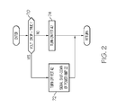
- FIG. 2 is a flow diagram representing an operation of the control unit of FIG. 1 according to this invention.
- the reference numeral 10 generally designates a portion of a vehicle electrical system, including a 12-volt storage battery 12, an engine starter motor 14, a start switch 16, and an audio system 18.
- the starter motor 14 and start switch 16 are depicted because closure of start switch 16 for engine cranking is typically the most severe load borne by battery 12, and produces a sudden and substantial drop in the voltage supplied to audio system 18 by battery 12.
- the audio system 18 includes a power supply circuit 20, a power amplifier 22, a voltage regulator 24, a vacuum fluorescent (VF) display 26, a microprocessor-based control unit 28, a tuner 30, and one or more loudspeakers 32.
- the power supply circuit 20 supplies filtered battery voltage (i.e., 12-volts) to power amplifier 22, voltage regulator 24, and display 26; and voltage regulator 24 supplies a lower regulated voltage (5-volts, for example) to control unit 28 and tuner 30.
- Battery voltage filtering is achieved by the combination of series inductor 34 and the filter capacitors 36, 38 and 40.
- a power field-effect-transistor (FET) 42 couples the inductor 34 to filter capacitor 36 to provide a filtered 12-volt supply voltage for power amplifier 22 at terminal 44 when power FET 42 is conductive (on).
- a first power diode 46 couples inductor 34 to filter capacitor 38 to provide a filtered 12-volt supply voltage for voltage regulator 24 at terminal 48; and a second power diode 50 couples inductor 34 to filter capacitor 40 to provide a filtered 12-volt supply voltage for display 26 at terminal 52.
- the power FET 42 is a normally-off device, and control unit 28 selectively biases FET 42 on through driver circuit 54 to provide a low-resistance circuit path between inductor 34 and terminal 44.
- control unit 28 selectively biases FET 42 on through driver circuit 54 to provide a low-resistance circuit path between inductor 34 and terminal 44.
- power amplifier 22 can be electrically isolated from storage battery 12 when the audio system 18 is not activated and when the battery voltage suddenly drops, due to activation of starter motor 14 for example.
- isolating terminal 44 from storage battery 12 prevents filter capacitor 36 from discharging through the starter motor 14, and provides sufficient reserve energy to enable power amplifier 22 to carry out its power-down function.
- the first power diode 46 and filter capacitor 38 perform a similar function for voltage regulator 24, as do the second power diode 50 and filter capacitor 40 for display 26.
- a third power diode could be used in place of the FET 42, but the voltage drop across FET 42 is much less than the voltage drop across a forward-biased diode, so that substantially full battery voltage is available to power amplifier 22 at terminal 44 during operation of the audio system 18. Additionally, the maximum current requirement of power amplifier 22 would produce significantly higher heat dissipation in a diode than in FET 42 due to its low on-resistance. On the other hand, the input voltage and current requirements of voltage regulator 24 and display 26 are substantially less than that of power amplifier 22, so that the forward voltage drops and heat dissipation of diodes 46 and 48 do not pose significant design considerations. Additionally, FETs could theoretically be used in place of the second and third power diodes 46 and 50, but the power diodes 46 and 50 function adequately at a substantially lower cost.
- the power diode 50 may be omitted to reduce the power supply cost, particularly in applications where it is not important for the VF display 26 to be operative during engine cranking. Also, if a liquid-crystal-diode (LCD) display is used in place of the VF display 26, it can be powered by the voltage regulator 24; in this case, the second power diode 50 and capacitor 40 can be omitted.
- LCD liquid-crystal-diode
- the audio system 18 operates in one of two modes depending on the state of the vehicle ignition switch (not shown).
- voltage regulator 24 supplies control unit 28 a low current stand-by operating voltage (SB) on line 56, sufficient to supply time-of-day data to display 26 via line 58.
- SB stand-by operating voltage
- the other functions of audio system 18 are inactive, and the power FET 42 remains in its normal off state.
- Reverse battery voltage occurring during the stand-by mode is isolated from power amplifier 22 by FET 42, and from voltage regulator 24 and display 26 by the first and second power diodes 46 and 50, respectively.
- voltage regulator 24 supplies operating voltage to tuner 30 via line 60, and main power (MP) to control unit 28 via line 62, to transition from the stand-by mode to the on mode.
- control unit 28 turns on FET 42 via driver 54, sends a frequency signal to tuner 30 via line 64 if appropriate, and suitably activates display 26 via line 58.
- the tuner output is supplied to power amplifier 22 via line 66, and power amplifier 22 drives the loudspeakers 32 accordingly.
- control unit 28 issues a "Shut-Down" command to power amplifier 22 via line 68 to activate muting and power-down functions.
- the flow diagram of FIG. 2 represents a software routine periodically executed by control unit 28 during the on mode of audio system 18.
- the battery terminal voltage VBAT (or a signal ratiometrically related to VBAT) is supplied to an A/D input port of control unit 28, and block 70 of the flow diagram depicted in FIG. 2 monitors the input signal to detect a sudden negative-going voltage transition such as can occur when the starter motor 14 is activated. If the voltage drop condition is detected, block 70 is answered in the affirmative and block 72 is executed to turn off FET 42, and to signal power amplifier 22 to activate the Shut-Down function.
- the filter capacitor 36 provides sufficient reserve energy to enable power amplifier 22 to respond by muting the audio output to loudspeakers 32 and performing a controlled power down.
- crank switch input may be supplied to control unit 28 as indicated in phantom in FIG. 1 ; when a state change of the CR input indicates closure of crank switch 16, block 72 is executed as described above to turn off FET 42 and command the shut-down of power amplifier 22.
- the power supply circuit 20 provides a simple and cost-effective arrangement for protecting audio system 18 and eliminating undesired system operation due to supply voltage anomalies. While the invention has been described with respect to the illustrated embodiment, it is recognized that numerous modifications and variations in addition to those mentioned herein will occur to those skilled in the art. Accordingly, it is intended that the invention not be limited to the disclosed embodiment, but that it have the full scope permitted by the language of the following claims.
Landscapes
- Engineering & Computer Science (AREA)
- Power Engineering (AREA)
- Amplifiers (AREA)
Abstract
A power supply circuit (10) for a vehicle audio system (18) supplies a regulated voltage to a control unit (28) through a series diode (46) and full battery voltage to a power amplifier (22) through a normally-off series power-FET (42). When the audio system (18) is activated, the control unit (28) turns on the series power-FET (42) to permit operation of the power amplifier (22). If the control unit (28) detects a sudden voltage drop or an engine crank signal (70), it prevents audible loudspeaker sounds by immediately turning off the series power-FET (42) and issuing a shut-down command to the power amplifier (22). If the battery voltage (12) is reversed, the series diode (46) isolates the control unit (28), and the series power-FET (42) remains off.
Description
- The present invention relates to a vehicle audio system, and more particularly to a power supply circuit therefor.
- The audio system in a motor vehicle is subject to various power fluctuations and irregularities that have the potential to damage the system circuitry and/or cause undesired system operation. For example, the system must be protected from reverse voltages that occur when the battery cables are incorrectly installed. And power fluctuations that produce audible loudspeaker sounds can occur with little or no warning. Accordingly, what is needed is a power supply arrangement that protects the audio system and eliminates undesired system operation.
- The present invention is directed to an improved power supply circuit for an audio system including a power amplifier that operates at full battery voltage and a control unit that operates at a lower regulated voltage. Battery voltage is supplied to the control unit voltage regulator through a series diode and to the power amplifier through a normally-off series power-FET. When the audio system is activated, the control unit turns on the series power-FET to permit operation of the power amplifier. If the control unit detects a sudden voltage drop or an engine crank signal, it prevents audible loudspeaker sounds by immediately turning off the series power-FET and issuing a shut-down command to the power amplifier. If the battery voltage is reversed, the series diode isolates the control unit, and the series power-FET remains off.
-
FIG. 1 is a diagram of a vehicle electrical system including an audio system having a microprocessor-based control unit and a power supply circuit according to this invention; -
FIG. 2 is a flow diagram representing an operation of the control unit ofFIG. 1 according to this invention. - Referring to the drawings, and particularly to
FIG. 1 , thereference numeral 10 generally designates a portion of a vehicle electrical system, including a 12-volt storage battery 12, anengine starter motor 14, astart switch 16, and anaudio system 18. Thestarter motor 14 andstart switch 16 are depicted because closure ofstart switch 16 for engine cranking is typically the most severe load borne bybattery 12, and produces a sudden and substantial drop in the voltage supplied toaudio system 18 bybattery 12. - The
audio system 18 includes apower supply circuit 20, apower amplifier 22, avoltage regulator 24, a vacuum fluorescent (VF)display 26, a microprocessor-basedcontrol unit 28, atuner 30, and one or more loudspeakers 32. Thepower supply circuit 20 supplies filtered battery voltage (i.e., 12-volts) topower amplifier 22,voltage regulator 24, anddisplay 26; andvoltage regulator 24 supplies a lower regulated voltage (5-volts, for example) to controlunit 28 andtuner 30. Battery voltage filtering is achieved by the combination ofseries inductor 34 and thefilter capacitors inductor 34 to filtercapacitor 36 to provide a filtered 12-volt supply voltage forpower amplifier 22 atterminal 44 whenpower FET 42 is conductive (on). Afirst power diode 46couples inductor 34 tofilter capacitor 38 to provide a filtered 12-volt supply voltage forvoltage regulator 24 atterminal 48; and asecond power diode 50couples inductor 34 to filtercapacitor 40 to provide a filtered 12-volt supply voltage fordisplay 26 atterminal 52. - The
power FET 42 is a normally-off device, andcontrol unit 28 selectively biasesFET 42 on throughdriver circuit 54 to provide a low-resistance circuit path betweeninductor 34 andterminal 44. In this way,power amplifier 22 can be electrically isolated fromstorage battery 12 when theaudio system 18 is not activated and when the battery voltage suddenly drops, due to activation ofstarter motor 14 for example. In the case of a sudden drop in battery voltage, isolatingterminal 44 fromstorage battery 12 preventsfilter capacitor 36 from discharging through thestarter motor 14, and provides sufficient reserve energy to enablepower amplifier 22 to carry out its power-down function. Thefirst power diode 46 andfilter capacitor 38 perform a similar function forvoltage regulator 24, as do thesecond power diode 50 andfilter capacitor 40 fordisplay 26. Theoretically, of course, a third power diode could be used in place of theFET 42, but the voltage drop acrossFET 42 is much less than the voltage drop across a forward-biased diode, so that substantially full battery voltage is available topower amplifier 22 atterminal 44 during operation of theaudio system 18. Additionally, the maximum current requirement ofpower amplifier 22 would produce significantly higher heat dissipation in a diode than inFET 42 due to its low on-resistance. On the other hand, the input voltage and current requirements ofvoltage regulator 24 anddisplay 26 are substantially less than that ofpower amplifier 22, so that the forward voltage drops and heat dissipation ofdiodes third power diodes power diodes - In some cases, the
power diode 50 may be omitted to reduce the power supply cost, particularly in applications where it is not important for theVF display 26 to be operative during engine cranking. Also, if a liquid-crystal-diode (LCD) display is used in place of theVF display 26, it can be powered by thevoltage regulator 24; in this case, thesecond power diode 50 andcapacitor 40 can be omitted. - The
audio system 18 operates in one of two modes depending on the state of the vehicle ignition switch (not shown). When the ignition switch is off,voltage regulator 24 supplies control unit 28 a low current stand-by operating voltage (SB) online 56, sufficient to supply time-of-day data to display 26 vialine 58. In the stand-by mode, the other functions ofaudio system 18 are inactive, and the power FET 42 remains in its normal off state. Reverse battery voltage occurring during the stand-by mode is isolated frompower amplifier 22 byFET 42, and fromvoltage regulator 24 and display 26 by the first andsecond power diodes voltage regulator 24 supplies operating voltage to tuner 30 vialine 60, and main power (MP) to controlunit 28 vialine 62, to transition from the stand-by mode to the on mode. If theaudio system 18 is activated,control unit 28 turns on FET 42 viadriver 54, sends a frequency signal to tuner 30 vialine 64 if appropriate, and suitably activatesdisplay 26 vialine 58. The tuner output is supplied topower amplifier 22 vialine 66, andpower amplifier 22 drives the loudspeakers 32 accordingly. When a shut-down (SD) function is desired, controlunit 28 issues a "Shut-Down" command to poweramplifier 22 vialine 68 to activate muting and power-down functions. - The flow diagram of
FIG. 2 represents a software routine periodically executed bycontrol unit 28 during the on mode ofaudio system 18. The battery terminal voltage VBAT (or a signal ratiometrically related to VBAT) is supplied to an A/D input port ofcontrol unit 28, andblock 70 of the flow diagram depicted inFIG. 2 monitors the input signal to detect a sudden negative-going voltage transition such as can occur when thestarter motor 14 is activated. If the voltage drop condition is detected,block 70 is answered in the affirmative andblock 72 is executed to turn offFET 42, and to signalpower amplifier 22 to activate the Shut-Down function. As mentioned above thefilter capacitor 36 provides sufficient reserve energy to enablepower amplifier 22 to respond by muting the audio output to loudspeakers 32 and performing a controlled power down. When the voltage drop condition is no longer True,block 70 is answered in the negative andblock 74 is executed to turn onFET 42 to resume normal operation ofaudio system 18. Alternatively or additionally, a crank switch input (CR) may be supplied to controlunit 28 as indicated in phantom inFIG. 1 ; when a state change of the CR input indicates closure ofcrank switch 16,block 72 is executed as described above to turn offFET 42 and command the shut-down ofpower amplifier 22. - In summary, the
power supply circuit 20 provides a simple and cost-effective arrangement for protectingaudio system 18 and eliminating undesired system operation due to supply voltage anomalies. While the invention has been described with respect to the illustrated embodiment, it is recognized that numerous modifications and variations in addition to those mentioned herein will occur to those skilled in the art. Accordingly, it is intended that the invention not be limited to the disclosed embodiment, but that it have the full scope permitted by the language of the following claims.
Claims (6)
- Apparatus for supplying power from a vehicle storage battery (12) to an audio system (18), comprising:a power transistor (42) coupling said storage battery (12) to a first power supply terminal (44);a power diode (46) coupling said storage battery (12) to a second power supply terminal (48);first and second filter capacitors (36, 38) coupled to said first and second power supply terminals (44, 48), respectively;an audio system power amplifier (22) coupled to said first power supply terminal (44) for driving an audio system loudspeaker (32); andan audio system controller (24, 28) coupled to said second power supply terminal (48) for turning on said power transistor (42) during an on-mode of said audio system (18) and selectively turning off said power transistor (42) to electrically isolate said storage battery (12) from said audio system power amplifier (22) when a sudden voltage drop of said storage battery (12) is detected or anticipated.
- The apparatus of claim 1, where:said power transistor (42) is a low on-resistance power FET.
- The apparatus of claim 1, where:said audio system controller includes a voltage regulator (24) coupled to said second power supply terminal (48) and a microprocessor-based control unit (28) powered by an output voltage of said voltage regulator (24).
- The apparatus of claim 3, where:said control unit (28) turns off said power transistor (42, 72) in response to a detected sudden voltage drop of said storage battery (12, 70).
- The apparatus of claim 3, including a starter switch (16) for activating an electrical load (14) coupled to said storage battery (12), where:said control unit (28) turns off said power transistor (42) in response to a detected closure (CR) of said starter switch (16).
- The apparatus of claim 1, where:said audio system controller (24, 28)commands a shut-down of said audio system power amplifier (22) when the sudden voltage drop of said storage battery (12) is detected or anticipated (72).
Applications Claiming Priority (1)
| Application Number | Priority Date | Filing Date | Title |
|---|---|---|---|
| US11/983,251 US20090121555A1 (en) | 2007-11-08 | 2007-11-08 | Vehicle audio system power supply |
Publications (1)
| Publication Number | Publication Date |
|---|---|
| EP2058920A2 true EP2058920A2 (en) | 2009-05-13 |
Family
ID=40456275
Family Applications (1)
| Application Number | Title | Priority Date | Filing Date |
|---|---|---|---|
| EP20080167492 Pending EP2058920A2 (en) | 2007-11-08 | 2008-10-24 | Vehicle audio system power supply |
Country Status (2)
| Country | Link |
|---|---|
| US (1) | US20090121555A1 (en) |
| EP (1) | EP2058920A2 (en) |
Cited By (1)
| Publication number | Priority date | Publication date | Assignee | Title |
|---|---|---|---|---|
| WO2015145006A1 (en) * | 2014-03-28 | 2015-10-01 | Peugeot Citroen Automobiles Sa | System for stabilising power supply voltage when starting an engine in a vehicle |
Families Citing this family (2)
| Publication number | Priority date | Publication date | Assignee | Title |
|---|---|---|---|---|
| US9780749B2 (en) * | 2013-03-20 | 2017-10-03 | Ford Global Technologies, Llc | Radio mute strategy for non-can radios used with smart starting systems |
| CN113242502B (en) * | 2021-03-22 | 2022-07-26 | 苏州上声电子股份有限公司 | A kind of car audio system and its speaker open circuit detection method |
Family Cites Families (10)
| Publication number | Priority date | Publication date | Assignee | Title |
|---|---|---|---|---|
| US4460264A (en) * | 1981-09-01 | 1984-07-17 | W. Haking Enterprises, Ltd. | Electronic camera with automatic battery shutdown |
| US5594629A (en) * | 1994-06-20 | 1997-01-14 | General Electric Company | High-frequency switching circuits operable in a natural zero-voltage switching mode |
| US6104248A (en) * | 1998-10-23 | 2000-08-15 | Carver; Robert W. | Audio amplifier with tracking power supply utilizing inductive power converters |
| JP2001196998A (en) * | 2000-01-14 | 2001-07-19 | Matsushita Electric Ind Co Ltd | Emergency call system terminal equipment and emergency call system |
| US7110839B2 (en) * | 2000-10-02 | 2006-09-19 | Harman International Industries, Incorporated | Audio system for minimizing the chance that high power audio signals may be directed to a headphone jack |
| DE10211609B4 (en) * | 2002-03-12 | 2009-01-08 | Hüttinger Elektronik GmbH & Co. KG | Method and power amplifier for generating sinusoidal high-frequency signals for operating a load |
| US7483539B2 (en) * | 2002-11-08 | 2009-01-27 | Bose Corporation | Automobile audio system |
| FR2853471B1 (en) * | 2003-04-01 | 2005-06-24 | St Microelectronics Sa | AUDIO AMPLIFIER CIRCUIT |
| US20060093155A1 (en) * | 2004-11-03 | 2006-05-04 | Fiori David Jr | Interface enhancement apparatus |
| JP4212569B2 (en) * | 2005-04-01 | 2009-01-21 | 株式会社デンソー | Switching device |
-
2007
- 2007-11-08 US US11/983,251 patent/US20090121555A1/en not_active Abandoned
-
2008
- 2008-10-24 EP EP20080167492 patent/EP2058920A2/en active Pending
Cited By (2)
| Publication number | Priority date | Publication date | Assignee | Title |
|---|---|---|---|---|
| WO2015145006A1 (en) * | 2014-03-28 | 2015-10-01 | Peugeot Citroen Automobiles Sa | System for stabilising power supply voltage when starting an engine in a vehicle |
| FR3019396A1 (en) * | 2014-03-28 | 2015-10-02 | Peugeot Citroen Automobiles Sa | VOLTAGE STABILIZATION SYSTEM |
Also Published As
| Publication number | Publication date |
|---|---|
| US20090121555A1 (en) | 2009-05-14 |
Similar Documents
| Publication | Publication Date | Title |
|---|---|---|
| JP5408352B2 (en) | Power supply control circuit and power supply control device | |
| US11142150B2 (en) | Apparatus for managing power of vehicle and method of controlling the same | |
| CN112440912A (en) | Vehicle power supply system | |
| EP2858223A1 (en) | Power supply circuit for vehicle | |
| US7830108B2 (en) | Device for supplying electrical power to a fuel pump of a motor vehicle internal combustion engine | |
| JP2022081465A (en) | Smart connection device, start power supply, and battery clamp | |
| EP2058920A2 (en) | Vehicle audio system power supply | |
| JP4149415B2 (en) | Boost power supply control device and failure site identification method for boost power supply control device | |
| JP3610950B2 (en) | Power supply | |
| JP2009015380A (en) | Power supply device and electronic control device | |
| CN102457168B (en) | Controlled voltage filter | |
| US20050127983A1 (en) | Voltage booster device having voltage-suppressing circuit | |
| JP5140322B2 (en) | Vehicle power supply | |
| JP4307875B2 (en) | Audio output circuit | |
| CN106134081B (en) | Load driving circuits | |
| JP2002354878A (en) | Motor driving power supply | |
| KR102559727B1 (en) | Low voltage dc to dc converter for vehicles with over-current output shut-off function and control method thereof | |
| KR102699786B1 (en) | Circuit and method for anomaly detection in vehicle power distribution circuit for minimazing parasitic current | |
| JP2000092750A (en) | Power circuit | |
| CN101576736B (en) | Power supply circuit of automobile electronic controller | |
| JPH0822336A (en) | Driving device for inductance load | |
| JPH06339233A (en) | Power source switching apparatus | |
| JPH02280419A (en) | Radio communication equipment and its power supply | |
| JP4244965B2 (en) | Power supply | |
| JP2020137235A (en) | Vehicle power supply device |
Legal Events
| Date | Code | Title | Description |
|---|---|---|---|
| PUAI | Public reference made under article 153(3) epc to a published international application that has entered the european phase |
Free format text: ORIGINAL CODE: 0009012 |
|
| STAA | Information on the status of an ep patent application or granted ep patent |
Free format text: STATUS: THE APPLICATION HAS BEEN PUBLISHED |
|
| AK | Designated contracting states |
Kind code of ref document: A2 Designated state(s): AT BE BG CH CY CZ DE DK EE ES FI FR GB GR HR HU IE IS IT LI LT LU LV MC MT NL NO PL PT RO SE SI SK TR |
|
| AX | Request for extension of the european patent |
Extension state: AL BA MK RS |