EP2058835A1 - Autofocussing method - Google Patents
Autofocussing method Download PDFInfo
- Publication number
- EP2058835A1 EP2058835A1 EP07120434A EP07120434A EP2058835A1 EP 2058835 A1 EP2058835 A1 EP 2058835A1 EP 07120434 A EP07120434 A EP 07120434A EP 07120434 A EP07120434 A EP 07120434A EP 2058835 A1 EP2058835 A1 EP 2058835A1
- Authority
- EP
- European Patent Office
- Prior art keywords
- value
- defocus
- focus
- images
- image
- Prior art date
- Legal status (The legal status is an assumption and is not a legal conclusion. Google has not performed a legal analysis and makes no representation as to the accuracy of the status listed.)
- Withdrawn
Links
- 238000000034 method Methods 0.000 title claims abstract description 60
- 239000000523 sample Substances 0.000 claims description 9
- 238000003384 imaging method Methods 0.000 claims description 6
- 238000004088 simulation Methods 0.000 claims description 3
- 230000008859 change Effects 0.000 description 6
- 230000004075 alteration Effects 0.000 description 5
- 230000004044 response Effects 0.000 description 5
- 239000004065 semiconductor Substances 0.000 description 5
- 235000012431 wafers Nutrition 0.000 description 4
- 239000000428 dust Substances 0.000 description 3
- 238000004519 manufacturing process Methods 0.000 description 3
- 239000002245 particle Substances 0.000 description 3
- 238000012935 Averaging Methods 0.000 description 2
- 230000009286 beneficial effect Effects 0.000 description 2
- 238000010586 diagram Methods 0.000 description 2
- 230000003287 optical effect Effects 0.000 description 2
- 238000012937 correction Methods 0.000 description 1
- 230000007547 defect Effects 0.000 description 1
- 238000001514 detection method Methods 0.000 description 1
- 238000002474 experimental method Methods 0.000 description 1
- 238000007689 inspection Methods 0.000 description 1
- 150000002500 ions Chemical class 0.000 description 1
- 230000007246 mechanism Effects 0.000 description 1
- 230000008569 process Effects 0.000 description 1
- 238000012545 processing Methods 0.000 description 1
Images

Classifications
-
- G—PHYSICS
- G01—MEASURING; TESTING
- G01N—INVESTIGATING OR ANALYSING MATERIALS BY DETERMINING THEIR CHEMICAL OR PHYSICAL PROPERTIES
- G01N21/00—Investigating or analysing materials by the use of optical means, i.e. using sub-millimetre waves, infrared, visible or ultraviolet light
- G01N21/84—Systems specially adapted for particular applications
- G01N21/88—Investigating the presence of flaws or contamination
- G01N21/8851—Scan or image signal processing specially adapted therefor, e.g. for scan signal adjustment, for detecting different kinds of defects, for compensating for structures, markings, edges
-
- G—PHYSICS
- G02—OPTICS
- G02B—OPTICAL ELEMENTS, SYSTEMS OR APPARATUS
- G02B21/00—Microscopes
- G02B21/0004—Microscopes specially adapted for specific applications
- G02B21/002—Scanning microscopes
- G02B21/0024—Confocal scanning microscopes (CSOMs) or confocal "macroscopes"; Accessories which are not restricted to use with CSOMs, e.g. sample holders
- G02B21/0052—Optical details of the image generation
- G02B21/006—Optical details of the image generation focusing arrangements; selection of the plane to be imaged
-
- G—PHYSICS
- G02—OPTICS
- G02B—OPTICAL ELEMENTS, SYSTEMS OR APPARATUS
- G02B7/00—Mountings, adjusting means, or light-tight connections, for optical elements
- G02B7/28—Systems for automatic generation of focusing signals
-
- H—ELECTRICITY
- H01—ELECTRIC ELEMENTS
- H01J—ELECTRIC DISCHARGE TUBES OR DISCHARGE LAMPS
- H01J37/00—Discharge tubes with provision for introducing objects or material to be exposed to the discharge, e.g. for the purpose of examination or processing thereof
- H01J37/02—Details
- H01J37/21—Means for adjusting the focus
-
- H—ELECTRICITY
- H01—ELECTRIC ELEMENTS
- H01J—ELECTRIC DISCHARGE TUBES OR DISCHARGE LAMPS
- H01J37/00—Discharge tubes with provision for introducing objects or material to be exposed to the discharge, e.g. for the purpose of examination or processing thereof
- H01J37/26—Electron or ion microscopes; Electron or ion diffraction tubes
- H01J37/28—Electron or ion microscopes; Electron or ion diffraction tubes with scanning beams
-
- G—PHYSICS
- G01—MEASURING; TESTING
- G01N—INVESTIGATING OR ANALYSING MATERIALS BY DETERMINING THEIR CHEMICAL OR PHYSICAL PROPERTIES
- G01N21/00—Investigating or analysing materials by the use of optical means, i.e. using sub-millimetre waves, infrared, visible or ultraviolet light
- G01N21/84—Systems specially adapted for particular applications
- G01N21/88—Investigating the presence of flaws or contamination
- G01N21/95—Investigating the presence of flaws or contamination characterised by the material or shape of the object to be examined
- G01N21/956—Inspecting patterns on the surface of objects
- G01N2021/95638—Inspecting patterns on the surface of objects for PCB's
-
- H—ELECTRICITY
- H01—ELECTRIC ELEMENTS
- H01J—ELECTRIC DISCHARGE TUBES OR DISCHARGE LAMPS
- H01J2237/00—Discharge tubes exposing object to beam, e.g. for analysis treatment, etching, imaging
- H01J2237/21—Focus adjustment
- H01J2237/216—Automatic focusing methods
-
- H—ELECTRICITY
- H01—ELECTRIC ELEMENTS
- H01J—ELECTRIC DISCHARGE TUBES OR DISCHARGE LAMPS
- H01J2237/00—Discharge tubes exposing object to beam, e.g. for analysis treatment, etching, imaging
- H01J2237/22—Treatment of data
- H01J2237/221—Image processing
Definitions
- the invention further relates to software for programming a programmable controller of an apparatus, the apparatus equipped with a focusing device capable of being set to different focal values, the software comprising code for programming the apparatus to perform the method.
- a focusing method is described for a space based telescope.
- the telescope is diffraction limited.
- focus determination should be achieved without the conventional focus slew.
- the Simfit method described involves forming a series of simulated point-source images for a range of focus settings, using a model for the (aberrations of the) telescope. An obtained image is then compared with the series of simulated images to determine the defocus value. The defocus value thus determined can then be used to focus the telescope.
- the method was successfully used to focus the Spitzer Space Telescope (see " The state of focus and image quality of the Spitzer Space Telescope as measured in orbit", R.D. Gehrz et al., Proceedings of the SPIE Optical, Infrared, and Millimeter Space Telescopes, Volume 5487, pp. 166-176, Oct 2004 ).
- the known method compares an image of a object, such as a star, with a series of images representing the simulated response of the telescope for a point source at different defocus settings.
- a point source is an object that is so small that its geometrical image is much less than the optimum resolution of the image formed.
- the series of images representing the simulated response are obtained by ray-tracing. Comparing the image with the series of images representing the simulated response gives a 'best fit' and an estimate of the defocus. By correcting the focal setting by the defocus value of the telescope thus estimated the telescope is focused.
- a disadvantage of the known method is that it shows good results for focusing a diffraction limited telescope imaging stars, but that it does not provide a solution for objects that are not point sources.
- a star can for all practical cases be treated as a point source.
- the series of images representing the simulated response to a point source are a series of images of the optical aberrations of the telescope, which can be derived from a model of the telescope.
- the object is not a point-source, and the image is at least partially determined by the extend of the object the series of images representing the simulated response of the telescope for a point source do not match the image.
- the sign of dF 1 is set to a positive or a negative value before F 2 is set.
- the chance that the estimated value for the defocus F1 has the correct sign is about 50%.
- the sign of the estimated value does not influence the chance to arrive at the correct value, so that it makes as much sense to change the focus to a smaller focal value as to change the focus to a larger focal value.
- the sign can thus be neglected. This is especially useful as the acquired image need only be compared to a series of images where no images corresponding with a positive defocus value are present, or where no images corresponding with a negative defocus value are present, thereby reducing the number of comparisons necessary.
- the image is formed by scanning a probe over the object.
- the method according to the invention for imaging objects in a SEM.
- a field of view is scanned with a probe of focused electrons.
- the method is especially advantageous for this type of instruments, as it is possible to achieve the correct setting of the focal value with a reduced field-of-view and/or at higher scan speed than when making the image of the object that is used for inspection or analysis.
- This makes an apparatus POSSIBLE capable of achieving high throughput for inspecting the quality of e.g. dies on a semiconductor wafer, measuring critical dimensions on a die, or inspecting critical dimensions during the production of heads used in hard-disk drives.
- the image is a line scan.
- the object When measuring critical dimensions the object often shows a bar or track in one direction, in which e.g. the width of the bar or track is the critical dimension.
- a minimum of scan time, and thus process time is used to obtain an image that can be used to focus.
- the critical dimension is often measured using a frame with a multitude of lines at slightly different positions, so that 'the' critical dimension can be determined, after focusing, by averaging over this multitude of lines.
- this frame need not be used for focusing, thereby offering a focusing method using less data points and thus improved processing time.
- the focus criterion is determined by comparing the second image with the through focus series of images.
- the defocus of the second image can be determined by comparing it with the through-focus series of images.
- the focus criterion is determined from features from the second image only.
- the defocus is estimated from features present in the second image itself.
- a criterion can be e.g. the rise time of a contrast signal while scanning over a bar.
- the apparatus is a particle-optical apparatus.
- the method can be used in e.g. a SEM, or an apparatus in which a beam of ions is focused on an object.
- the focus value F 1 is only set to a different focus value F 2 when the defocus dF 1 is larger than a predetermined value.
- Inventor used for his experiments a through-focus series of images made from a master object similar to the object to be imaged.
- This embodiment is especially useful for focusing e.g. semiconductor structures or the heads of hard disk drives during manufacturing said heads.
- the object and the master object form two positions on a larger object.
- the larger object may e.g. be a wafer, or a mask as used during wafer manufacturing.
- This embodiment describes the application of the method on e.g. semiconductor wafers, where many similar structures must be imaged so that e.g. defects can be found.
- the through-focus series of images is obtained by simulation, using at least a model representing the master object.
- the through-focus series of images may also be a simulated series of images.
- the simulated series can be based on a series of images obtained from a known object and 'translating' it to the master object to be used for the series of images, e.g. because the known object and the master object differ in shape (the known object and the master object may e.g. be mirror images).
- the simulated series may also be based on a model of both the object (e.g. a CAD model) and the optics of the apparatus forming the image.
- a multitude of images is made on different positions of the object, and the defocus value is determined by estimating the defocus value for each of the images, and a defocus value of the object is estimated by combining the defocus values for each of the images.
- This embodiment is especially beneficial when the object might show imperfect features or dust particles on some parts of the object.
- the areas from which the images are formed need not have identical aspect ratios.
- the defocus value of the object may be found by e.g. taking the average of the defocus values of the different areas, but that it may also be found by disregarding a part of the defocus values as they show a value which is markedly different from the defocus values of other areas.
- An aspect of the invention relates to software for programming a controller of an apparatus, the apparatus equipped with a focusing device capable of being set to different focal values, the software comprising code for programming the apparatus to perform the method according to the invention.
- such software can be stored on a computer readable medium, e.g. a CD or a DVD, but may also reside on a server computer and be interchanged between said server and the apparatus by e.g. internet.
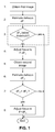
- FIG. 1 schematically shows a flow diagram of the method according to the invention.
- a through-focus series of the master object is obtained.
- a first image of the object is made using a focal value F 1 .
- the first image may be a line scan, but it may also be a 2D image of (part of the) object. It will be clear that it must be similar to the images of the through-focus series obtained of the master object, imaging an area with the same aspect ratio and a same area.
- the defocus of the first image dF 1 is estimated by comparing it with the through-focus series of the master object.
- Optional step 3 determines whether the defocus is already so small that no further focusing is needed.
- a second image is acquired. This second image is preferably the same area, or nominally the same area, as imaged in the first image, but it may be a different area comprising an identical feature, such as a slightly different part of a track on a semiconductor sample.
- the defocus of the second image is estimates. It may be estimated by comparison with the through-focus series of the master object, but it may also be estimated on the hand of information present in the second image, e.g.
- step 7 the defocus value of the second image is compared to the defocus value of the first image. If it is larger, then the adjustment of the focus in step 4 caused a larger defocus. Alternatively the defocus can be compared to a threshold value as used in step 3. In step 8 the focus is adjusted to a value of F 1 + dF 1 , which should be the correct value.
- the defocus can be determined after step 8 to determine whether proper focusing of the object occurred, or whether this was hindered by e.g. dust particles on the object or imperfections of features on the object.
- Figure 2 shows an image of an object in a Scanning Electron Microscope (SEM). It shows a (focused) image 21 of a semiconductor sample with a track 22 on its surface. In a SEM the sample is scanned with a finely focused beam of electrons. The impinging electrons cause e.g. secondary electrons to emanate from the sample. By detecting the secondary electrons the image is made. As can be seen the track 22 shows, in the focused image, a well-defined intensity change at position 23. Such an intensity change is representative for many well-focused features on numerous samples. By making one or more line scans 24 over this edge a first image is made. This first image is then compared with a through-focus series of a master object and the associated defocus is determined.
- SEM Scanning Electron Microscope
- the first image may be a 2D image of several lines 24 side-by-side, to be compared with a through-focus series of 2D images, but depending on the sample better results may be achieved using e.g. a single line scan along line 24, or a summation or average of several line scans along line 24, or the summation or average of several line scans displaced in the x-direction.
- Figure 3 schematically shows a through-focus series of line scans over the object shown in figure 2 . It shows for different defocus values the intensity as a function of the position along the scan line, that is: along the line 5 as shown in figure 1 . This may thus be the through-focus series of the master object.
- the intensity and defocus value are given in arbitrary units, and the line scan comprises some 57 discrete positions along line 5 of figure 1 .
- an image of the object to be focused will resemble one of these intensity profiles.
- the defocus of the object is estimated.
- comparing can comprise e.g. simple subtraction of the intensity profiles, but may also include more sophisticated methods, such as methods comprising e.g. peak detection of the amplitude along the scan line, search for a gradient in the amplitude, or e.g. correlation techniques.
- the through-focus series may represent a larger or a smaller area or line scan than the image of the object, as this gives good results while correlating the image with the through focus series (provided that e.g. proper padding is done by adding e.g. zero's).
- the through-focus series is made on the hand of images made with a SEM of a master object, it is also possible to construct a through-focus series on the hand of models of the SEM and the master object, without forming a series of actual images.
- This simulation of the through-focus series can use e.g. a CAD model of the object.
- the through-focus series is e.g. made using multiple line scans and adding or averaging the multiple line scans so as to improve the signal-to-noise ratio.
- the method is used to obtain the defocus value of several line scans and take the average of the obtained defocus values. This is especially advantageous when the object may show irregularities at the scanned edge that may result in a line scan with reduced intensity step function.
- Figure 4 shows multiple line scans made on the object in a SEM.
- Figure 4 can be thought to be derived from figure 2 .
- not one image 24 is made to determine the defocus value
- several images (here in the form of line scans) 25A, 25B and 25C are made to determine the defocus value.
- 25A, 25B and 25C are made to determine the defocus value.
- a defocus value is estimated by comparing it with a through-focus series of a similar area of the master object, and the defocus value for the object is determined by combining the defocus value found for each of the areas. This is especially beneficial when the object might show imperfect features or dust particles on some parts of the object.
- the areas from which the images are formed need not have identical aspect ratios.
- the defocus value of the object may be found by e.g. taking the average of the defocus values of the different areas, but that it may also be found by disregarding a part of the defocus values found if they show a value which is markedly different from the defocus values of other areas.
Landscapes
- Physics & Mathematics (AREA)
- Chemical & Material Sciences (AREA)
- Analytical Chemistry (AREA)
- General Physics & Mathematics (AREA)
- Optics & Photonics (AREA)
- Computer Vision & Pattern Recognition (AREA)
- Engineering & Computer Science (AREA)
- Signal Processing (AREA)
- Health & Medical Sciences (AREA)
- Life Sciences & Earth Sciences (AREA)
- Biochemistry (AREA)
- General Health & Medical Sciences (AREA)
- Immunology (AREA)
- Pathology (AREA)
- Automatic Focus Adjustment (AREA)
Abstract
The invention relates to a method for focusing an object in e.g. a scanning electron microscope. A first image of an object is acquired using a first focal value F1, and the defocus dF1 of the image is estimated by comparing the image with a series of through-focus images of a master object. Said through-focus series comprises images of similar areas of another, similar object. The focus of the SEM is now corrected by setting the focal value to F1 - dF1. However, as known to the person skilled in the art, there is a chance that the correct value is F1 + dF1, as equal amounts of under- and over focus give very similar images. Therefore the defocus is estimated again, and when the defocus is larger than the first defocus, the focal value is set to F1 + dF1.
Description
- The invention relates to a method for forming a focused image of an object by an apparatus, the apparatus equipped with a focusing device capable of being set to different focal values, the method comprising: deriving a through-focus series of images of a master object similar to the object to be imaged, each image of the series of images associated with a defocus value, setting the focal value to a first focal value F1, obtain a first image of the object, comparing the image with the through focus series of images and determining an estimate of a first defocus value dF1, and changing the focus to a second focal value F2 = F1 - dF1.
The invention further relates to software for programming a programmable controller of an apparatus, the apparatus equipped with a focusing device capable of being set to different focal values, the software comprising code for programming the apparatus to perform the method. - Such a method is known from "Simfit and Focus Diversity: methods for determining the focus of the SIRTF telescope in space without a focus slew", W.F. Hoffmann et al., Proceedings of SPIE IR Space Telescopes and Instruments, Volume 4850, pp. 428-440, March 2003.
- In the mentioned paper a focusing method is described for a space based telescope. The telescope is diffraction limited. To minimise possible lock-up of the focusing mechanism in space, focus determination should be achieved without the conventional focus slew. The Simfit method described involves forming a series of simulated point-source images for a range of focus settings, using a model for the (aberrations of the) telescope. An obtained image is then compared with the series of simulated images to determine the defocus value. The defocus value thus determined can then be used to focus the telescope. The method was successfully used to focus the Spitzer Space Telescope (see "The state of focus and image quality of the Spitzer Space Telescope as measured in orbit", R.D. Gehrz et al., Proceedings of the SPIE Optical, Infrared, and Millimeter Space Telescopes, Volume 5487, pp. 166-176, Oct 2004).
- The known method compares an image of a object, such as a star, with a series of images representing the simulated response of the telescope for a point source at different defocus settings.
In this context a point source is an object that is so small that its geometrical image is much less than the optimum resolution of the image formed.
The series of images representing the simulated response are obtained by ray-tracing.
Comparing the image with the series of images representing the simulated response gives a 'best fit' and an estimate of the defocus. By correcting the focal setting by the defocus value of the telescope thus estimated the telescope is focused. - A disadvantage of the known method is that it shows good results for focusing a diffraction limited telescope imaging stars, but that it does not provide a solution for objects that are not point sources. As known to the person skilled in the art, a star can for all practical cases be treated as a point source. As also known the series of images representing the simulated response to a point source are a series of images of the optical aberrations of the telescope, which can be derived from a model of the telescope. However, in the case that the object is not a point-source, and the image is at least partially determined by the extend of the object the series of images representing the simulated response of the telescope for a point source do not match the image.
This is also hinted at in the known paper, in the text accompanyingfigure 2 , where it says that a secondary peak on the opposite side of best focus is shown, where the image is similarly blurred from defocus, but has a very different structure. However, when imaging objects that are not point sources, the "very different structure" only contributes to image changes in a minor way and it may be difficult to distinguish between the two peaks. - Another disadvantage is that the method is very sensitive for the model used to determine the through-focus series. In
section 5 of the known document two methods for focusing the telescope are discussed (Simfit and Focus Diversity), and it states that "Simfit is most sensitive to model error, Focus Diversity to random noise". For a diffraction limited telescope the aberrations may be known with sufficient precision, but this need not be the case for other instruments. When using e.g. a scanning electron microscope (SEM), where the aberrations depend on many variables, such as beam energy, spot size, scan speed, scan distortion, setting of the stigmator, distance between objective lens and object, interference by stray magnetic fields, etc., the appearances (e.g. form and/or magnitude) of these aberrations are often not sufficiently known, although they reproduce from image to image. - It is an object of the invention to provide an improved focusing method.
- To that end the method according to the invention is characterized in that
- the master object is not a point-source,
- a second image is formed,
- an estimate of a second defocus value is determined using a focus criterion, and,
- if the absolute value of the second defocus value is larger than the absolute value of the first defocus value dF1, the focal value is set to F3 = F1 + dF1.
- Inventor applied the known method to images made using a Scanning Electron Microscope, comparing an image of an object with a through-focus series of images from the same or a similar object. It was found, as mentioned before, that for non-point sources the sign of the defocus cannot be determined reliably, as equal amounts of under- and over focus give very similar images. As a result there is a chance that, when changing the focal value F1 to F2 = F1 - dF1, the correction is in the wrong direction and the absolute value of the defocus becomes twice as large.
By now determining the defocus value in the second image formed, it is determined whether the focal value F1 is set to the correct focal value. If this is not the case, the focal value is set to the correct value, that is: the focal value is set to F3 = F1 + dF1. - In an embodiment of the method according to the invention the sign of dF1 is set to a positive or a negative value before F2 is set.
- Inventor found that for many applications, e.g. applications using a SEM, the chance that the estimated value for the defocus F1 has the correct sign is about 50%. In this case the sign of the estimated value does not influence the chance to arrive at the correct value, so that it makes as much sense to change the focus to a smaller focal value as to change the focus to a larger focal value. The sign can thus be neglected. This is especially useful as the acquired image need only be compared to a series of images where no images corresponding with a positive defocus value are present, or where no images corresponding with a negative defocus value are present, thereby reducing the number of comparisons necessary.
- In another embodiment of the method according to the invention the sign of dF1 is inverted before F2 is set.
- Effectively this means that, instead of setting F2 to the value F2 = F1 - dF1, F2 is set to the value F2 = F1 + dF1, and instead of setting F3 to the value F3 = F1 + dF1, F3 is set to the value F3 = F1 - dF1. So, instead of using a subtraction an addition may be used, as long as addition is used where originally a subtraction is used.
- In yet another embodiment of the method according to the invention the image is formed by scanning a probe over the object.
- As already mentioned inventor used the method according to the invention for imaging objects in a SEM. In such an instrument a field of view is scanned with a probe of focused electrons. The method is especially advantageous for this type of instruments, as it is possible to achieve the correct setting of the focal value with a reduced field-of-view and/or at higher scan speed than when making the image of the object that is used for inspection or analysis. This makes an apparatus POSSIBLE capable of achieving high throughput for inspecting the quality of e.g. dies on a semiconductor wafer, measuring critical dimensions on a die, or inspecting critical dimensions during the production of heads used in hard-disk drives.
- In a further embodiment of the method according to the invention the image is a line scan.
- When measuring critical dimensions the object often shows a bar or track in one direction, in which e.g. the width of the bar or track is the critical dimension. By scanning a line in a direction perpendicular to this bar or track, a minimum of scan time, and thus process time, is used to obtain an image that can be used to focus.
- It is noted that the critical dimension is often measured using a frame with a multitude of lines at slightly different positions, so that 'the' critical dimension can be determined, after focusing, by averaging over this multitude of lines. However, this frame need not be used for focusing, thereby offering a focusing method using less data points and thus improved processing time.
- In another embodiment of the method according to the invention the focus criterion is determined by comparing the second image with the through focus series of images.
- In this embodiment the defocus of the second image can be determined by comparing it with the through-focus series of images.
- In yet another embodiment of the method according to the invention the focus criterion is determined from features from the second image only.
- In this embodiment the defocus is estimated from features present in the second image itself. Such a criterion can be e.g. the rise time of a contrast signal while scanning over a bar.
- In still another embodiment of the method according to the invention the apparatus is a particle-optical apparatus.
- The method can be used in e.g. a SEM, or an apparatus in which a beam of ions is focused on an object.
- In yet another embodiment of the method according to the invention the focus value F1 is only set to a different focus value F2 when the defocus dF1 is larger than a predetermined value.
- If the first image is already sufficiently in focus, there is no need to change the focus.
- In another embodiment of the method according to the invention the through-focus series of images of the master object is obtained by imaging the master object
- Inventor used for his experiments a through-focus series of images made from a master object similar to the object to be imaged. This embodiment is especially useful for focusing e.g. semiconductor structures or the heads of hard disk drives during manufacturing said heads.
- In a further embodiment of the method according to the invention the object and the master object form two positions on a larger object.
- The larger object may e.g. be a wafer, or a mask as used during wafer manufacturing.
- This embodiment describes the application of the method on e.g. semiconductor wafers, where many similar structures must be imaged so that e.g. defects can be found.
- In another embodiment of the method according to the invention the through-focus series of images is obtained by simulation, using at least a model representing the master object.
- The through-focus series of images may also be a simulated series of images. The simulated series can be based on a series of images obtained from a known object and 'translating' it to the master object to be used for the series of images, e.g. because the known object and the master object differ in shape (the known object and the master object may e.g. be mirror images). The simulated series may also be based on a model of both the object (e.g. a CAD model) and the optics of the apparatus forming the image.
- In yet another embodiment of the method according to the invention the through-focus series does not comprise images with a positive defocus or does not comprise images with a negative defocus
- Especially in the cases where the blurring of the image for a positive defocus is similar to the blurring of the image of a negative defocus, sign of the defocus is neglected, there is no reason to compare the first image for each defocus setting of the series of through-focus images with two images, one with a positive defocus and the other with a negative defocus.
- In still another embodiment of the method according to the invention a multitude of images is made on different positions of the object, and the defocus value is determined by estimating the defocus value for each of the images, and a defocus value of the object is estimated by combining the defocus values for each of the images.
- This embodiment is especially beneficial when the object might show imperfect features or dust particles on some parts of the object.
It is noted that the areas from which the images are formed need not have identical aspect ratios.
It is further noted that the defocus value of the object may be found by e.g. taking the average of the defocus values of the different areas, but that it may also be found by disregarding a part of the defocus values as they show a value which is markedly different from the defocus values of other areas. - An aspect of the invention relates to software for programming a controller of an apparatus, the apparatus equipped with a focusing device capable of being set to different focal values, the software comprising code for programming the apparatus to perform the method according to the invention.
- As known to the person skilled in the art, such software can be stored on a computer readable medium, e.g. a CD or a DVD, but may also reside on a server computer and be interchanged between said server and the apparatus by e.g. internet.
- The invention is now further elucidated on the basis of schematic drawings, where corresponding features are identified by identical numerals. To this end:
-
figure 1 schematically shows a flow diagram of the method according to the invention, -
figure 2 shows an image of an object in a SEM, -
figure 3 schematically shows a series of through-focus line scans over the object shown infigure 1 , and -
figure 4 shows multiple line scans made on the object in a SEM. -
Figure 1 schematically shows a flow diagram of the method according to the invention.
Before the part of the method shown in the flow chart is executed, a through-focus series of the master object is obtained.
In step 1 a first image of the object is made using a focal value F1. The first image may be a line scan, but it may also be a 2D image of (part of the) object. It will be clear that it must be similar to the images of the through-focus series obtained of the master object, imaging an area with the same aspect ratio and a same area.
Instep 2 the defocus of the first image dF1 is estimated by comparing it with the through-focus series of the master object.
Optional step 3 determines whether the defocus is already so small that no further focusing is needed. Whether this is attractive depends on how likely it is that the object is sufficiently in focus.
Instep 4 the focus is adjusted by the defocus value found instep 2 to F2 = F1-dF1.
In step 5 a second image is acquired. This second image is preferably the same area, or nominally the same area, as imaged in the first image, but it may be a different area comprising an identical feature, such as a slightly different part of a track on a semiconductor sample.
Instep 6 the defocus of the second image is estimates. It may be estimated by comparison with the through-focus series of the master object, but it may also be estimated on the hand of information present in the second image, e.g. by determining a FWHM width of the peak in the image or the 80/20 contrast change in the image of a track.
Instep 7 the defocus value of the second image is compared to the defocus value of the first image. If it is larger, then the adjustment of the focus instep 4 caused a larger defocus. Alternatively the defocus can be compared to a threshold value as used instep 3.
Instep 8 the focus is adjusted to a value of F1 + dF1, which should be the correct value. - It is noted that optionally the defocus can be determined after
step 8 to determine whether proper focusing of the object occurred, or whether this was hindered by e.g. dust particles on the object or imperfections of features on the object. -
Figure 2 shows an image of an object in a Scanning Electron Microscope (SEM). It shows a (focused)image 21 of a semiconductor sample with atrack 22 on its surface. In a SEM the sample is scanned with a finely focused beam of electrons. The impinging electrons cause e.g. secondary electrons to emanate from the sample. By detecting the secondary electrons the image is made. As can be seen thetrack 22 shows, in the focused image, a well-defined intensity change atposition 23. Such an intensity change is representative for many well-focused features on numerous samples. By making one or more line scans 24 over this edge a first image is made. This first image is then compared with a through-focus series of a master object and the associated defocus is determined.
It is noted that the first image may be a 2D image ofseveral lines 24 side-by-side, to be compared with a through-focus series of 2D images, but depending on the sample better results may be achieved using e.g. a single line scan alongline 24, or a summation or average of several line scans alongline 24, or the summation or average of several line scans displaced in the x-direction. -
Figure 3 schematically shows a through-focus series of line scans over the object shown infigure 2 . It shows for different defocus values the intensity as a function of the position along the scan line, that is: along theline 5 as shown infigure 1 . This may thus be the through-focus series of the master object. The intensity and defocus value are given in arbitrary units, and the line scan comprises some 57 discrete positions alongline 5 offigure 1 . Here a set of 5 intensity profiles are given, from best focus (dF = 0) to well out of focus (dF = 4). - Depending on how well the sample is focused, an image of the object to be focused will resemble one of these intensity profiles. By comparing the image of the object with the through-focus set, the defocus of the object is estimated.
- It is noted that comparing can comprise e.g. simple subtraction of the intensity profiles, but may also include more sophisticated methods, such as methods comprising e.g. peak detection of the amplitude along the scan line, search for a gradient in the amplitude, or e.g. correlation techniques.
- It is further noted that the through-focus series may represent a larger or a smaller area or line scan than the image of the object, as this gives good results while correlating the image with the through focus series (provided that e.g. proper padding is done by adding e.g. zero's).
- It is also noted that, although the example show only 5 curves associated with 5 different defocus values, in reality many more curves may be used.
- It is also noted that, although here the through-focus series is made on the hand of images made with a SEM of a master object, it is also possible to construct a through-focus series on the hand of models of the SEM and the master object, without forming a series of actual images. This simulation of the through-focus series can use e.g. a CAD model of the object.
It is also possible that the through-focus series is e.g. made using multiple line scans and adding or averaging the multiple line scans so as to improve the signal-to-noise ratio. Another possibility is that the method is used to obtain the defocus value of several line scans and take the average of the obtained defocus values. This is especially advantageous when the object may show irregularities at the scanned edge that may result in a line scan with reduced intensity step function. -
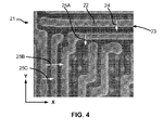
Figure 4 shows multiple line scans made on the object in a SEM.
Figure 4 can be thought to be derived fromfigure 2 . Here however not oneimage 24 is made to determine the defocus value, but several images (here in the form of line scans) 25A, 25B and 25C are made to determine the defocus value. For each of theimages
It is noted that the areas from which the images are formed need not have identical aspect ratios.
It is further noted that the defocus value of the object may be found by e.g. taking the average of the defocus values of the different areas, but that it may also be found by disregarding a part of the defocus values found if they show a value which is markedly different from the defocus values of other areas.
Claims (15)
- Method for forming a focused image of an object with an apparatus, the apparatus equipped with a focusing device capable of being set to different focal values, the method comprising:• obtaining a through-focus series of images of a master object, said master object similar to the object to be imaged, each image of the series of images associated with a defocus value,• setting the focal value to a first focal value F1,• obtain a first image of the object (1),• comparing the image with the through-focus series of images and determining an estimate of a first defocus value dF1 (2), and• setting the focus to a second focal value F2 = F1 - dF1 (4),characterized in that• the master object is not a point-source,• a second image is formed (5),• an estimate of a second defocus value is determined using a focus criterion (6), and• if the absolute value of the second defocus value is larger than the absolute value of the first defocus value dF1 (7), the focal value is set to F3 = F1 + dF1 (8).
- The method according to claim 1 in which the sign of dF1 is set to a positive or a negative value before F2 is set.
- The method according to claim 1 in which the sign of dF1 is inverted before F2 is set.
- The method according to any of the preceding claims in which the first and the second images are formed by scanning a probe over the object.
- The method according to claim 4 in which the first and the second images are line scans (24, 25A, 25B, 25C).
- The method according to any of the preceding claims in which the focus criterion is determined by comparing the second image with the through-focus series of images.
- The method according to any of claims 1-5 in which the focus criterion is determined from features from the second image only.
- The method according to any of the preceding claims in which the apparatus is a particle-optical apparatus.
- The method according to any of the preceding claims in which the focus value F1 is only set to a different focus value F2 when the defocus dF1 is larger than a predetermined value (3).
- The method according to any of the preceding claims in which the through-focus series of images of the master object is obtained by imaging the master object.
- The method according to claim 10 in which the object and the master object form two positions on a larger object.
- The method according to any of claims 1-9 in which the through-focus series of images is obtained by simulation, using at least a model representing the master object.
- The method according to any of the preceding claims in which the through focus series does not comprise images with a positive defocus or does not comprise images with a negative defocus.
- The method according to any of the preceding claims in which a multitude of images (24, 25A, 25B, 25C) is made on different positions of the object, and the defocus value is determined by estimating the defocus value for each of the images, and a defocus value of the object is estimated by combining the defocus values for each of the images.
- Software for programming a programmable controller of an apparatus, the apparatus equipped with a focusing device capable of being set to different focal values, the software comprising code for programming the apparatus to perform the method according to any of the preceding claims.
Priority Applications (1)
| Application Number | Priority Date | Filing Date | Title |
|---|---|---|---|
| EP07120434A EP2058835A1 (en) | 2007-11-12 | 2007-11-12 | Autofocussing method |
Applications Claiming Priority (1)
| Application Number | Priority Date | Filing Date | Title |
|---|---|---|---|
| EP07120434A EP2058835A1 (en) | 2007-11-12 | 2007-11-12 | Autofocussing method |
Publications (1)
| Publication Number | Publication Date |
|---|---|
| EP2058835A1 true EP2058835A1 (en) | 2009-05-13 |
Family
ID=39271315
Family Applications (1)
| Application Number | Title | Priority Date | Filing Date |
|---|---|---|---|
| EP07120434A Withdrawn EP2058835A1 (en) | 2007-11-12 | 2007-11-12 | Autofocussing method |
Country Status (1)
| Country | Link |
|---|---|
| EP (1) | EP2058835A1 (en) |
Cited By (1)
| Publication number | Priority date | Publication date | Assignee | Title |
|---|---|---|---|---|
| EP4220683A3 (en) * | 2022-01-28 | 2023-12-13 | FEI Company | Automatic particle beam focusing |
Citations (2)
| Publication number | Priority date | Publication date | Assignee | Title |
|---|---|---|---|---|
| EP1396872A1 (en) * | 2001-06-15 | 2004-03-10 | Riken | Electron microscope and its focal point control method |
| US20060209309A1 (en) * | 2005-03-18 | 2006-09-21 | Illumina, Inc. | Systems for and methods of facilitating focusing an optical scanner |
-
2007
- 2007-11-12 EP EP07120434A patent/EP2058835A1/en not_active Withdrawn
Patent Citations (2)
| Publication number | Priority date | Publication date | Assignee | Title |
|---|---|---|---|---|
| EP1396872A1 (en) * | 2001-06-15 | 2004-03-10 | Riken | Electron microscope and its focal point control method |
| US20060209309A1 (en) * | 2005-03-18 | 2006-09-21 | Illumina, Inc. | Systems for and methods of facilitating focusing an optical scanner |
Non-Patent Citations (2)
| Title |
|---|
| GEHRZ R D ET AL: "The state of the focus and image quality of the Spitzer Space Telescope as measured in orbit", OPTICAL, INFRARED, AND MILLIMETER SPACE TELESCOPES 21-25 JUNE 2005 GLASGOW, UK, vol. 5487, no. 1, 2004, Proceedings of the SPIE - The International Society for Optical Engineering SPIE-Int. Soc. Opt. Eng USA, pages 166 - 176, XP002477188, ISSN: 0277-786X * |
| HOFFMANN W F ET AL: "Simfit and Focus Diversity: methods for determining the focus of the SIRTF telescope in space without a focus slew", IR SPACE TELESCOPES AND INSTRUMENTS 24-28 AUG. 2002 WAIKOLOA, HI, USA, vol. 4850, 2003, Proceedings of the SPIE - The International Society for Optical Engineering SPIE-Int. Soc. Opt. Eng USA, pages 428 - 440, XP002477377, ISSN: 0277-786X * |
Cited By (2)
| Publication number | Priority date | Publication date | Assignee | Title |
|---|---|---|---|---|
| EP4220683A3 (en) * | 2022-01-28 | 2023-12-13 | FEI Company | Automatic particle beam focusing |
| US12327342B2 (en) | 2022-01-28 | 2025-06-10 | Fei Company | Automatic particle beam focusing |
Similar Documents
| Publication | Publication Date | Title |
|---|---|---|
| US20110187847A1 (en) | Scanning type charged particle microscope device and method for processing image acquired with scanning type charged particle microscope device | |
| KR102748451B1 (en) | Method and system for noise mitigation in multibeam scanning electron microscope system | |
| JP2008177064A (en) | Scanning charged particle microscope apparatus and method for processing images acquired by scanning charged particle microscope apparatus | |
| CN100341106C (en) | Method and device for aligning a charged particle beam column | |
| US8712184B1 (en) | Method and system for filtering noises in an image scanned by charged particles | |
| US9002097B1 (en) | Method and system for enhancing image quality | |
| JP2014041081A (en) | Defect detection method | |
| JP4500099B2 (en) | Electron microscope apparatus system and dimension measuring method using electron microscope apparatus system | |
| JP4553889B2 (en) | Determination method of aberration coefficient in aberration function of particle optical lens | |
| KR102936423B1 (en) | Learning method and image generation system of learning machine | |
| JP6055768B2 (en) | Focus correction value contamination inspection | |
| CN117470836A (en) | Computer-implemented method, measuring device and computer program product | |
| JP2012142299A (en) | Scanning charged particle microscope device, and processing method of image taken by scanning charged particle microscope device | |
| JP5178558B2 (en) | Method for adjusting optical axis of charged particle beam and charged particle beam apparatus | |
| KR20220131852A (en) | Image creation for inspection of semiconductor specimens | |
| JP2006153837A (en) | Scanning electron microscope, pattern measurement method using the same, and machine difference correction apparatus for scanning electron microscope | |
| JP2009523241A (en) | APPARATUS, METHOD, AND COMPUTER PROGRAM FOR IMPROVING ARTIFICIAL RESOLUTION IN OPTICAL SYSTEM | |
| US9523645B2 (en) | Lenticular wafer inspection | |
| JP4829584B2 (en) | Method for automatically adjusting electron beam apparatus and electron beam apparatus | |
| TWI843354B (en) | Charged particle beam device and inspection method using the same | |
| KR20070065244A (en) | Pattern Recognition Matching for Brightfield Imaging of Low Contrast Semiconductor Devices | |
| JP2008218259A (en) | Inspection method and inspection apparatus | |
| WO2022102266A1 (en) | Image correction device, pattern inspection device and image correction method | |
| CN116959943B (en) | Methods for determining the aberrations of charged particle beams and charged particle beam systems | |
| JP4995542B2 (en) | Autofocus method of charged particle beam apparatus, computer program, and recording medium |
Legal Events
| Date | Code | Title | Description |
|---|---|---|---|
| PUAI | Public reference made under article 153(3) epc to a published international application that has entered the european phase |
Free format text: ORIGINAL CODE: 0009012 |
|
| AK | Designated contracting states |
Kind code of ref document: A1 Designated state(s): AT BE BG CH CY CZ DE DK EE ES FI FR GB GR HU IE IS IT LI LT LU LV MC MT NL PL PT RO SE SI SK TR |
|
| AX | Request for extension of the european patent |
Extension state: AL BA HR MK RS |
|
| AKX | Designation fees paid | ||
| REG | Reference to a national code |
Ref country code: DE Ref legal event code: 8566 |
|
| STAA | Information on the status of an ep patent application or granted ep patent |
Free format text: STATUS: THE APPLICATION IS DEEMED TO BE WITHDRAWN |
|
| 18D | Application deemed to be withdrawn |
Effective date: 20091114 |