EP2058804A1 - Method for dereverberation of an acoustic signal - Google Patents
Method for dereverberation of an acoustic signal Download PDFInfo
- Publication number
- EP2058804A1 EP2058804A1 EP07021334A EP07021334A EP2058804A1 EP 2058804 A1 EP2058804 A1 EP 2058804A1 EP 07021334 A EP07021334 A EP 07021334A EP 07021334 A EP07021334 A EP 07021334A EP 2058804 A1 EP2058804 A1 EP 2058804A1
- Authority
- EP
- European Patent Office
- Prior art keywords
- reverberation
- signal
- energy
- component
- acoustic signal
- Prior art date
- Legal status (The legal status is an assumption and is not a legal conclusion. Google has not performed a legal analysis and makes no representation as to the accuracy of the status listed.)
- Granted
Links
Images




Classifications
-
- G—PHYSICS
- G10—MUSICAL INSTRUMENTS; ACOUSTICS
- G10L—SPEECH ANALYSIS TECHNIQUES OR SPEECH SYNTHESIS; SPEECH RECOGNITION; SPEECH OR VOICE PROCESSING TECHNIQUES; SPEECH OR AUDIO CODING OR DECODING
- G10L21/00—Speech or voice signal processing techniques to produce another audible or non-audible signal, e.g. visual or tactile, in order to modify its quality or its intelligibility
- G10L21/02—Speech enhancement, e.g. noise reduction or echo cancellation
- G10L21/0208—Noise filtering
-
- G—PHYSICS
- G10—MUSICAL INSTRUMENTS; ACOUSTICS
- G10L—SPEECH ANALYSIS TECHNIQUES OR SPEECH SYNTHESIS; SPEECH RECOGNITION; SPEECH OR VOICE PROCESSING TECHNIQUES; SPEECH OR AUDIO CODING OR DECODING
- G10L21/00—Speech or voice signal processing techniques to produce another audible or non-audible signal, e.g. visual or tactile, in order to modify its quality or its intelligibility
- G10L21/02—Speech enhancement, e.g. noise reduction or echo cancellation
- G10L21/0208—Noise filtering
- G10L2021/02082—Noise filtering the noise being echo, reverberation of the speech
Definitions
- This invention relates to a method for estimating a reverberation signal component of an acoustic signal, a method for dereverberation of the acoustic signal and to a system therefor.
- the invention relates particularly to the dereverberation of a microphone signal in a room or a vehicle cabin.
- the enhancement of the quality of audio and speech signals in a communication system is a central topic in acoustic, and in particular speech signal processing.
- the communication between two parties is often carried out in a noisy background environment and noise reduction as well as echo compensation are necessary in order to guarantee intelligibility.
- Prominent examples are hands-free voice communication systems in vehicles and automatic speech recognition units.
- a sound source e.g. a speaking person or a loudspeaker
- a sound source emanates an acoustic signal that propagates trough the room.
- the microphone After the sound that reaches the microphone in a direct path reflections at the room boundaries also reach the microphone with some delay.
- the speech spectrum smears over time. In Fig. 1 such a situation is shown.
- a person 10 inside a room 11 which could be a vehicle cabin or any other room utters speech which is detected by a microphone 12.
- the acoustic signal of the speaking person 10 has a direct sound component 13 and a reverberation signal component 14 originating from the sound reflected at the room boundaries.
- the reflections at the wall boundaries induce a signal component resulting in a reverberant speech as also shown by the spectrograms shown in Fig. 2 .
- a spectrogram for a clean speech result without reverberation is shown, whereas in the right part of Fig. 2 , the smearing over time for the reverberant speech can be seen.
- the reverberation is visible as a smearing in time direction.
- the invention may be particularly, but not exclusively, applied in hands-free telecommunication systems or automatic speech recognition systems.
- a method for estimating a reverberation signal component of the acoustic signal is provided, the acoustic signal containing a direct sound component and the reverberation component.
- the acoustic signal is detected by a microphone and the reverberation signal component is estimated.
- an incorrect reverberation signal component R ⁇ is calculated under the assumption that the reverberation signal component has a predetermined relationship to the direct sound component.
- the error resulting from this assumption that the reverberation signal component has a predetermined relationship to the direct sound component is minimized.
- a predetermined relationship may be that the reverberation signal component corresponds to the direct sound component, or that the reverberation signal component and the direction sound component have a predetermined ratio, or that the direct sound signal energy and the reverberation signal energy have a predetermined ratio or the like.
- the reverberation signal component can be estimated by calculating an incorrect reverberation signal component and to use this calculation for determining the correct reverberation signal component. Once the reverberation signal component is known, the reverberation signal component can be subtracted from the acoustic signal in order to attenuate reverberation.
- the step of minimizing the error does not mean that the error is determined and minimized in an approximation procedure.
- the step of minimizing the error should refer to the calculation of the correct reverberation signal component based on the calculation of the incorrect reverberation signal component.
- 2 of the reverberation signal component is estimated.
- 2 of the incorrect signal component is calculated for which the reverberation energy equals a direct sound energy.
- the reverberation signal energy is put on a level with the direct sound energy.
- the error resulting from this assumption can be removed by minimizing a quotient Q as will be explained in detail further below.
- the acoustic signal detected by the microphone is considered being a digital signal, meaning that the electric microphone signal was already subject to an analogue to digital conversion.
- the sample microphone signal may then be transformed into the frequency domain.
- the time domain microphone signal may be divided in short time frames, each time frame signal having a predetermined number of sampling values.
- Each time frame signal can then be fully transformed into the frequency domain resulting in a frame based spectrum for each of the time domain frames.
- Preferably all the calculation steps discussed herein below will be carried out in the frequency domain.
- a parameter A is calculated corresponding to the ratio of the direct sound signal energy to the reverberation signal energy.
- A is the ratio of the direct sound signal energy to the reverberation signal energy
- A is set to 1 for the calculation of the incorrect reverberation signal component.
- the reverberation signal energy is recursively calculated on the basis of a delayed signal spectrum of the acoustic signal and on the basis of the reverberation signal energy calculated in an earlier step of the recursive calculating method.
- the reverberation signal energy is regressively estimated by using the following equation:
- 2 Y ⁇ ⁇ k - D 2 ⁇ A ⁇ ⁇ e - ⁇ ⁇ ⁇ D + R ⁇ ⁇ ⁇ k - 1 2 ⁇ e - ⁇ ⁇
- Y ⁇ ( k ) is the Fourier transformed microphone signal component, k being the time index of the undersampled signal in the frequency domain, ⁇ indicating the frequency band, D being a predetermined delay, A ⁇ corresponding to the parameter A mentioned above, R ⁇ being the (correct) reverberation signal energy, Y ⁇ being a parameter describing the decay of the reverberation signal energy.
- the parameter Y ⁇ mainly depends on the shape and the size of the room in which the microphone signal is detected such as the size of the room or the sound absorption of the boundary walls.
- the parameter A describes the ratio of the direct sound component and the reverberation component and mainly depends on the position of the speaker uttering the acoustic signal relative to the position of the microphone picking up the acoustic signal.
- a ratio Q is determined indicating the ratio of the acoustic signal energy
- the minimization of the error comprises the step of minimizing the ratio Q .
- the parameter A corresponding to the ratio of the direct signal energy to the reverberation signal energy is found, and as a consequence the reverberation signal energy can be determined.
- filter coefficients of a digital filter used for filtering the acoustic signal can be determined, the filter being used for dereverberation of the acoustic signal..
- the minimization of Q can be interpreted as a solution when the speaker abruptly stops to utter an acoustic signal, the microphone detecting in this case only the reverberation signal components.
- speech pauses are followed by speech uttered by the speaking person.
- the reverberation signal energy needed for determining the filter coefficient of the filter for filtering the acoustic signal can be calculated.
- sophisticated speech activation detecting units would be needed accurately detecting when speech is uttered and when no speech is uttered by the user.
- the correct value of A could be determined.
- speech activity detecting unit necessary to detect the speech pauses need not to be provided.
- the speech pauses can be detected when the quotient Q is minimized.
- the minimum value of Q is calculated, a value of A is obtained which corresponds to the situation when the user has uttered a sound signal abruptly stopping after the utterance.
- the parameter A corresponding to the ratio of the direct signal energy to the reverberation signal energy may be dependent on time as the distance between the user and the microphone need not to be constant.
- the parameter A when the user is approaching the microphone, the parameter A will increase, whereas the parameter A will decrease when the speaking user moves away from the microphone.
- the parameter A may be time-dependent and may be therefore calculated continuously over time.
- the parameter may increase again when the user approaches the microphone.
- the parameter A can be slowly incremented over time in order to be able to detect a new minimum value of A that is larger than the previously determined parameter A .
- the parameter A could be increased too much.
- a course speech detector may be used. When a longer pause in the speech is detected the increment of A may be stopped in order to avoid that the value of A gets to high resulting in difficulties to again minimize the parameter A during speech.
- the invention furthermore relates to a method for dereverberation of the acoustic signal, the method comprising the step of detecting the acoustic signal by the microphone and of estimating the reverberation signal component as explained in more detail above.
- the acoustic signal can be attenuated by especially attenuating the reverberation signal component.
- the reverberation signal component is attenuated with the use of a digital filter.
- a digital filter is a Wiener-Filter.
- the filter coefficients for this Wiener-Filter can be calculated when the acoustic signal energy and the reverberation signal energy is known.
- the reverberation signal energy can be calculated by calculating A .
- the reverberation signal energy can be calculated using the above-mentioned equation 1.
- the signal energy of the acoustic signal is known from the detected microphone signal.
- the dereverberation can be carried out by calculating the parameter A , calculating the reverberation signal energy, determining the filter coefficients on the basis of the calculated reverberation signal energy and filtering the acoustic signal using the calculated filter coefficients.
- the filtering can be carried out for each of the frames of the Fourier transform signal. After filtering the different filtered frames can be retransformed into the time domain and the time domain can be built from the different filtered and Fourier transformed signals.
- the resulting filtered acoustic signal has less reverberation components, thus facilitating the perceivability of the filtered acoustic signal.
- the energy of the microphone signal X(k) in the frequency domain is approximated by the energy of the direct sound and the energy of the reverberation signal R(k),
- 2 X ⁇ k 2 + R ⁇ k 2 .
- the acoustic signal as detected was approximated by having the direct sound (speech) component and the reverberation component.
- the method of the invention is often used in a noisy environment so that the noise component cannot be neglected.
- the noise component is attenuated in addition to the reverberation component.
- the noise energy and the reverberation energy are determined and noise filter coefficients are calculated on the basis of the estimated noise energy and reverberation filter coefficients are calculated on the basis of the estimated reverberation energy.
- the acoustic signal is then filtered using the noise filter coefficients and the reverberation filter coefficients.
- a noise reduced signal as a basis for the estimation of the reverberation energy, the noise reduced signal being filtered using the noise filter coefficients.
- a reverberation reduced signal for estimating the noise energy the reverberation reduced signal being a signal which was filtered using the reverberation filter coefficients.
- one of the signals may be delayed before it is used for estimating the other signal energy.
- the noise-reduced signal may be calculated using the noise filter coefficients, and the noise reduced signal is delayed before it is transmitted to the reverberation filter.
- the delay of the noise reduced signal is not a problem for the reverberation estimation, as can be seen from equation 1, a signal is used, that was delayed by D cycles.
- the invention furthermore relates to a system for dereverberation of the acoustic signal, the system comprising a microphone detecting the acoustic signal, a digital filter filtering the acoustic signal for attenuating the reverberation component and a signal processing unit estimating the reverberation signal component by calculating an incorrect reverberation signal component under the assumption that the reverberation signal component has a predetermined relationship to the direct sound component.
- the signal processing unit furthermore uses the calculation of the incorrect reverberation signal component for calculating the (correct) reverberation signal component and the corresponding signal energy.
- the signal processing unit calculates the filter coefficients of the digital filter based on the calculated reverberation signal energy mentioned above.
- the digital filter then uses the calculated filter coefficients for attenuating the reverberation signal component.
- the invention furthermore relates to a hands-free telephony system comprising a system for dereverberation and a speech recognition system comprising the system for dereverberation as mentioned above.
- Fig. 1 shows a schematic view of a system helping to understand the existence of reverberation signal components in an acoustic signal.
- Fig. 2 shows on the left side a speech signal without reverberation components, and on the right side the same speech signal with reverberation components.
- Fig. 3 shows an example of a room impulse response explaining in further detail the existence of reverberation components.
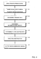
- Fig. 4 shows a flow chart comprising the basic steps for a method for dereverberation of an acoustic signal detected by a microphone.
- Fig. 5 shows a flow chart showing some of the dereverberation steps of Fig. 4 in more detail.
- Fig. 6 shows a schematic view of the system carrying out a noise reduction and a dereverberation.
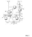
- Fig. 7 shows a more detailed view of the dereverberation component shown in Fig. 6 .
- Fig. 1 shows how the reverberation component of an acoustic signal emitted by the speaker 10 is generated.
- a loudspeaker 15 may be provided additionally emitting an acoustic signal with a direct component 16 and a reverberation component 17.
- the acoustic signal picked up by the microphone 12 now has direct sound signal components 13 and reverberation signal components 14.
- the detected signal is transmitted to a dereverberation unit 18 which attenuates the reverberation components as will be explained in more detail below.
- a model for reverberation and a time domain will be explained:
- D t denotes the threshold time index for the impulse response for classifying a path or reflection as wanted or unwanted.
- the reverberation time T 60 is defined as the time the reverberation needs to decay by 60 db.
- ⁇ 2 is a scaling factor for the entire energy of the impulse response.
- the time domain signal y ( n ) can be transformed into the frequency domain by a short-time Fourier transform (or into sub-band signals by a filter bank, respectively) resulting in the transformed signal Y ⁇ ( k ) .
- ⁇ denotes the index of the frequency bin or the index of the sub-band, respectively.
- An (energy) filter G ⁇ ( k ) models the energy decay of the room impulse response in the frequency or sub-band domain.
- Desired signal X ⁇ ( k ) and reverberation R ⁇ ( k ) are assumed to be uncorrelated despite this does not hold for early reverberation portions. Then the powers can be added linearly:
- the energy decay G ⁇ ( k ) is divided in a first part containing the first D frames which contributes to the desired signal energy
- R ⁇ k 2 ⁇ ⁇ l D ⁇ X c , ⁇ ⁇ k - l 2 ⁇ G ⁇ l
- the parameter A ⁇ accounts for the ratio of direct-path energy to reverberation energy.
- the parameter ⁇ ⁇ describes the decay of the reverberation energy. ⁇ ⁇ depends mainly on room parameters like room size or sound absorption at the walls, whereas A ⁇ depends mainly on the position of the speaker relative to the microphones.
- the delay D is a fixed parameter.
- the parameters A ⁇ and ⁇ ⁇ have to be identified for the specific environment.
- the parameter A is calculated, whereas, for the present invention, ⁇ ⁇ is considered to be known.
- Spectral subtraction is a frame based method for noise suppression which works on frequency domain signals.
- the spectral subtraction uses real valued coefficients W ⁇ ( k ) to scale the amplitudes of the distorted signal in each frame in order to get an estimate for X ⁇ ( k )
- X ⁇ ⁇ k Y ⁇ k ⁇ H ⁇ k
- ⁇ nn , ⁇ ( k ) denotes an estimate for the power density spectrum of the noise signal portion and ⁇ yy , ⁇ ( k ) denotes an estimate for the power density spectrum of the distorted signal.
- ⁇ yy , ⁇ ( k ) can be determined directly from the input signal it is mostly difficult to estimate the noise power density spectrum ⁇ nn , ⁇ ( k ). Further details on spectral subtraction can be found in E.
- 2 S ⁇ yy , ⁇ k
- the parameter ⁇ ⁇ is a parameter which can be calculated using a method as described in EP 06 016 029.8 filed by the same applicant.
- ⁇ ⁇ For the calculation of ⁇ ⁇ , reference is made to this patent application. In the following, the method for calculating the parameter A is described in more detail.
- Fig. 4 the main steps for dereverberation of an acoustic signal are shown.
- step 41 the acoustic signal detected by the microphone 12 is detected.
- step 42 the microphone signal is divided into frames after analogue to digital signal conversion and the different frames are transferred in the frequency domain by a Fourier transformation.
- the time domain signal is undersampled in such a way that e.g. 256 sampling values are contained in one sampling frame in the time domain.
- the next sampling frame in the time domain may overlap the first frame by offsetting the frame by N v sampling values.
- N v may be selected as being 64.
- the transform signal Y ⁇ ( k ) is obtained for each frame.
- the parameter A is determined by first calculating an incorrect reverberation signal energy as will be explained in further detail in connection with Fig. 5 further below.
- step 44 the reverberation energy is determined, the reverberation energy being used for determining the filter coefficients H ⁇ ( k ) as mentioned above in connection with equation 21 (step 45).
- the spectra microphone signal H ⁇ ( k ) can be filtered using the spectral subtraction method mentioned above (step 46).
- the dereverberated signal in the frequency domain may then be retransformed in the time domain by an inverse Fourier transformation.
- A may then be output as dereverberated signal (step 47).
- the dereverberated signal can be used as an input signal for a speech recognition system or a hands-free telephony system, or it can be output directly via a loudspeaker.
- the parameter A ⁇ has to be determined with a known parameter ⁇ ⁇ .
- the reverberation energy can be calculated based on the delayed signal spectrum and the estimated reverberation energy estimated in an earlier step of the recursive estimation method.
- an incorrect reverberation signal energy is calculated by simply setting the parameter A ⁇ in equation 15 to 1.
- 2 Y ⁇ ⁇ k - D 2 + R ⁇ ⁇ ⁇ k - 1 2 ⁇ e - ⁇ ⁇
- the minimum value of Q is the needed parameter A indicating the ratio of the direct sound signal to the reverberation sound signal.
- a ⁇ ⁇ k min Q A , ⁇ k , ⁇ ⁇ A ⁇ ⁇ ⁇ k - 1
- the reverberation energy can be determined in step 56 so that it is then possible as described in connection with Fig. 4 to determine the filter coefficients and to filter the microphone signal.
- the parameter A could theoretically be determined. By minimizing the quotient Q during the utterance of the speaking person is detected, the parameter A can be determined in an easy way without the need to detect the short speech pauses.
- the noise suppression and the reverberation suppression would be necessary.
- 2 These two values can then be added to be combined to a resulting perturbation energy.
- This resulting perturbation energy is used for calculating a common filter characteristic.
- the reverberation signal energy is calculated based on a noisy input signal and the noise signal energy is calculated based on a reverberation input signal.
- Fig. 6 a system is shown using a noise reduction and a separate reverberation reduction.
- the noise reduction is shown, whereas the reverberation reduction is shown in the left branch.
- the energy of the spectrum of the microphone signal is used as an input for the noise estimation unit 60.
- a noise signal energy can be calculated (
- the spectrum of the microphone signal is in the reverberation estimation unit 62, the reverberation signal energy
- a reverberation reduced signal Y(k). H R (k) as an input signal for the noise reduction. Doing both at the same time is hardly possible as the reverberation filter would be based on a noise reduced signal wherein the filter used for the noise reduction would be based on a dereverberated signal, that needed to be filtered with a filter to be calculated. This problem can be overcome by using the arrangement shown in Fig. 6 .
- the noise reduced signal is delayed by delay element 63 shown in Fig. 6 .
- the embodiment is shown where the dereverberated signal is used for the noise reduction.
- the reverberation signal energy is transmitted to the spectral subtraction unit SPS 64 resulting in the reverberation filter coefficient H R (k).
- the two filter coefficients are combined to H Ges (k).
- the spectrum of the detected microphone signal Y ⁇ (k) can be filtered in filtering unit 66. The result is the direct sound signal X ⁇ ⁇ (k).
- the microphone signal my be sampled at a sampling rate of about 11 kHz, sampling frames with a width of 256 samples in the time domain may be used for the Fourier transformation and an offset of subsequent sampling frames of 64 samples in the time domain may be used.
- the predetermined factor ⁇ for slowly increasing the value of A over time may be set to 1.001.
- Fig. 7 the reverberation estimation unit 62 is shown in more detail.
- the unit shown in Fig. 7 carries out the estimation of the reverberation energy as discussed in more detail above in connection with Fig. 4 and 5 .
- the filter coefficients calculated in an earlier calculation step are squared in unit 70.
- the spectrum of the microphone signal is retarded and multiplied with the output of unit 70 in unit 71.
- the delay element 72 the resulting signal is delayed by D-1 cycles.
- the result is then multiplied by e - ⁇ D in unit 73 resulting in the first term for calculating the incorrect reverberation energy shown by equation 15.
- 2 delayed by delay element 75 is multiplied by e - ⁇ in unit 76 and added to the output signal of unit 73 in unit 74.
- the signal at location 77 corresponds to the signal shown by equation 23.
- 2 is determined.
- This ratio is then minimized as symbolically shown by unit 79.
- the time increment by multiplying the minimized value by ⁇ is obtained in unit 80 together with the delay element 81 in order to arrive at ⁇ ( k ) as mentioned in equation 32.
- the correct reverberation energy can be calculated in unit 82 as also shown by equation 34.
- the result of the reverberation energy estimation is then, as shown in Fig. 6 , used for the spectral subtraction.
- this invention provides a method for dereverberation by suppressing the reverberant signal component on the basis of the spectral subtraction where the energy of the reverberant signal component is estimated by a simple statistical model.
- This invention describes a new method for estimating one of the two model parameters, namely the parameter A of the two parameters ⁇ ⁇ and A ⁇ .
- the advantage of the method is its efficiency and robustness while showing very good performance for dereverberation.
Landscapes
- Engineering & Computer Science (AREA)
- Computational Linguistics (AREA)
- Quality & Reliability (AREA)
- Signal Processing (AREA)
- Health & Medical Sciences (AREA)
- Audiology, Speech & Language Pathology (AREA)
- Human Computer Interaction (AREA)
- Physics & Mathematics (AREA)
- Acoustics & Sound (AREA)
- Multimedia (AREA)
- Circuit For Audible Band Transducer (AREA)
Abstract
- detecting the acoustic signal,
- estimating the reverberation signal component (14), wherein the estimating step comprises the step of
- calculating an incorrect reverberation signal component R̃ under the assumption that the reverberation signal component (14) has a predetermined relationship to the direct sound component (13), and
- minimizing the error resulting from the assumption that the reverberation signal component (14) has a predetermined relationship to the direct sound component (13) so as to estimate the reverberation signal component (14).
Description
- This invention relates to a method for estimating a reverberation signal component of an acoustic signal, a method for dereverberation of the acoustic signal and to a system therefor. The invention relates particularly to the dereverberation of a microphone signal in a room or a vehicle cabin.
- The enhancement of the quality of audio and speech signals in a communication system is a central topic in acoustic, and in particular speech signal processing. The communication between two parties is often carried out in a noisy background environment and noise reduction as well as echo compensation are necessary in order to guarantee intelligibility. Prominent examples are hands-free voice communication systems in vehicles and automatic speech recognition units.
- Of particular importance is the suppression of reverberation that can severely affect the quality of the audio signal. Reverberation especially impairs the performance of automatic speech recognizers. The acoustic phenomenon of reverberation can be described as follows: a sound source (e.g. a speaking person or a loudspeaker) emanates an acoustic signal that propagates trough the room. After the sound that reaches the microphone in a direct path reflections at the room boundaries also reach the microphone with some delay. Depending on the strength of the reflections and their time delays the speech spectrum smears over time. In
Fig. 1 such a situation is shown. Aperson 10 inside aroom 11 which could be a vehicle cabin or any other room utters speech which is detected by amicrophone 12. The acoustic signal of the speakingperson 10 has adirect sound component 13 and areverberation signal component 14 originating from the sound reflected at the room boundaries. The reflections at the wall boundaries induce a signal component resulting in a reverberant speech as also shown by the spectrograms shown inFig. 2 . On the left side, a spectrogram for a clean speech result without reverberation is shown, whereas in the right part ofFig. 2 , the smearing over time for the reverberant speech can be seen. The reverberation is visible as a smearing in time direction. - Several methods for the dereverberation of microphone signals are known in the art. For example, it is attempted to reduce dereverberation by means of deconvolution, i.e. inverse filtering using an estimate for the acoustic channel. Deconvolution can be performed in the time domain or in the cepstral domain. However, this kind of signal processing suffers from the dependence on accurate estimate of the acoustic channel which is in practical applications almost impossible. In an alternative approach, the direct path speech signal is processed by pitch enhancement or by linear predictive coding analysis. In a multi channel approach averaging over multiple microphone signals is performed to obtain a reduction of the reverberation contribution to the processed signal. However, these approaches cannot guarantee a sufficiently high quality of the wanted signal. In addition, implementation of the multi channel approaches are rather expensive.
- Despite the engineering process in recently as current dereverberation is still not satisfying and reliably enough for practical applications.
- Accordingly, a need exists to overcome the above-mentioned drawbacks and to provide a method and a system for dereverberation exhibiting an improved dereverberation of microphone signals. The invention may be particularly, but not exclusively, applied in hands-free telecommunication systems or automatic speech recognition systems.
- This need is met by the features of the independent claim. In the dependent claims, preferred embodiments of the invention are described.
- According to one aspect, a method for estimating a reverberation signal component of the acoustic signal is provided, the acoustic signal containing a direct sound component and the reverberation component. According to the method of the invention, the acoustic signal is detected by a microphone and the reverberation signal component is estimated. In this estimation step, an incorrect reverberation signal component R̃ is calculated under the assumption that the reverberation signal component has a predetermined relationship to the direct sound component. In an additional step, the error resulting from this assumption that the reverberation signal component has a predetermined relationship to the direct sound component is minimized. A predetermined relationship may be that the reverberation signal component corresponds to the direct sound component, or that the reverberation signal component and the direction sound component have a predetermined ratio, or that the direct sound signal energy and the reverberation signal energy have a predetermined ratio or the like. As will be explained and will be apparent from the following description a major advantage of the invention can be seen in the fact that a unit measuring the speech activity and detecting the pauses between the speech in an accurate way need not to be provided. The reverberation signal component can be estimated by calculating an incorrect reverberation signal component and to use this calculation for determining the correct reverberation signal component. Once the reverberation signal component is known, the reverberation signal component can be subtracted from the acoustic signal in order to attenuate reverberation.
- In the present case the step of minimizing the error does not mean that the error is determined and minimized in an approximation procedure. In the present context the step of minimizing the error should refer to the calculation of the correct reverberation signal component based on the calculation of the incorrect reverberation signal component.
- For estimating the reverberation signal component, a reverberation signal energy |R̂|2 of the reverberation signal component is estimated. In further detail an incorrect reverberation signal energy |R̃|2 of the incorrect signal component is calculated for which the reverberation energy equals a direct sound energy. In order to be able to carry out the calculation step, the reverberation signal energy is put on a level with the direct sound energy. In a further step, the error resulting from this assumption can be removed by minimizing a quotient Q as will be explained in detail further below. In this invention, the acoustic signal detected by the microphone is considered being a digital signal, meaning that the electric microphone signal was already subject to an analogue to digital conversion. The sample microphone signal may then be transformed into the frequency domain. The time domain microphone signal may be divided in short time frames, each time frame signal having a predetermined number of sampling values. Each time frame signal can then be fully transformed into the frequency domain resulting in a frame based spectrum for each of the time domain frames. Preferably all the calculation steps discussed herein below will be carried out in the frequency domain.
- For calculating the reverberation signal component or its energy a parameter A is calculated corresponding to the ratio of the direct sound signal energy to the reverberation signal energy. As mentioned above, for the estimation of the reverberation signal energy the assumption was made that the reverberation signal energy corresponded to the direct sound energy. As A is the ratio of the direct sound signal energy to the reverberation signal energy, A is set to 1 for the calculation of the incorrect reverberation signal component. When the parameter A is set to 1 an incorrect reverberation signal energy |R̃|2 can be calculated.
- According to one aspect of the invention, the reverberation signal energy is recursively calculated on the basis of a delayed signal spectrum of the acoustic signal and on the basis of the reverberation signal energy calculated in an earlier step of the recursive calculating method. Preferably, the reverberation signal energy is regressively estimated by using the following equation:

wherein Yµ (k) is the Fourier transformed microphone signal component, k being the time index of the undersampled signal in the frequency domain, µ indicating the frequency band, D being a predetermined delay, A µ corresponding to the parameter A mentioned above, R̂ being the (correct) reverberation signal energy, Y µ being a parameter describing the decay of the reverberation signal energy. The parameter Y µ mainly depends on the shape and the size of the room in which the microphone signal is detected such as the size of the room or the sound absorption of the boundary walls. The parameter A describes the ratio of the direct sound component and the reverberation component and mainly depends on the position of the speaker uttering the acoustic signal relative to the position of the microphone picking up the acoustic signal. - In one additional step of the calculation of A, a ratio Q is determined indicating the ratio of the acoustic signal energy |Y(k)|2 to the incorrect reverberation signal energy |R̃(k)|2. According to one aspect of the invention, the minimization of the error comprises the step of minimizing the ratio Q. When the minimum of the ratio Q is determined, the parameter A corresponding to the ratio of the direct signal energy to the reverberation signal energy is found, and as a consequence the reverberation signal energy can be determined. With the reverberation signal energy known, filter coefficients of a digital filter used for filtering the acoustic signal, can be determined, the filter being used for dereverberation of the acoustic signal..
- The minimization of Q can be interpreted as a solution when the speaker abruptly stops to utter an acoustic signal, the microphone detecting in this case only the reverberation signal components. In a speech signal speech pauses are followed by speech uttered by the speaking person. Theoretically, when a speech pause is detected, the reverberation signal energy needed for determining the filter coefficient of the filter for filtering the acoustic signal, can be calculated. However, to this end, sophisticated speech activation detecting units would be needed accurately detecting when speech is uttered and when no speech is uttered by the user. During a speech pause, the correct value of A could be determined. According to the present invention, speech activity detecting unit necessary to detect the speech pauses need not to be provided. Mathematically, the speech pauses can be detected when the quotient Q is minimized. When the minimum value of Q is calculated, a value of A is obtained which corresponds to the situation when the user has uttered a sound signal abruptly stopping after the utterance.
- The parameter A corresponding to the ratio of the direct signal energy to the reverberation signal energy may be dependent on time as the distance between the user and the microphone need not to be constant. By way of example, when the user is approaching the microphone, the parameter A will increase, whereas the parameter A will decrease when the speaking user moves away from the microphone. As a consequence, the parameter A may be time-dependent and may be therefore calculated continuously over time. When a minimum of the parameter A has been calculated, the parameter may increase again when the user approaches the microphone. In order to take this situation into account, the parameter A can be slowly incremented over time in order to be able to detect a new minimum value of A that is larger than the previously determined parameter A.
- In the case of longer speech pauses, the parameter A could be increased too much. In order to avoid the situation a course speech detector may be used. When a longer pause in the speech is detected the increment of A may be stopped in order to avoid that the value of A gets to high resulting in difficulties to again minimize the parameter A during speech.
- The invention furthermore relates to a method for dereverberation of the acoustic signal, the method comprising the step of detecting the acoustic signal by the microphone and of estimating the reverberation signal component as explained in more detail above. When the reverberation signal component is estimated, the acoustic signal can be attenuated by especially attenuating the reverberation signal component. According to one aspect of the invention, the reverberation signal component is attenuated with the use of a digital filter. One embodiment of such a digital filter is a Wiener-Filter. The filter coefficients for this Wiener-Filter can be calculated when the acoustic signal energy and the reverberation signal energy is known. As mentioned above, the reverberation signal energy can be calculated by calculating A. When the parameter A is known, the reverberation signal energy can be calculated using the above-mentioned
equation 1. The signal energy of the acoustic signal is known from the detected microphone signal. - Summarizing, according to one aspect of the invention, the dereverberation can be carried out by calculating the parameter A, calculating the reverberation signal energy, determining the filter coefficients on the basis of the calculated reverberation signal energy and filtering the acoustic signal using the calculated filter coefficients. The filtering can be carried out for each of the frames of the Fourier transform signal. After filtering the different filtered frames can be retransformed into the time domain and the time domain can be built from the different filtered and Fourier transformed signals. The resulting filtered acoustic signal has less reverberation components, thus facilitating the perceivability of the filtered acoustic signal.
- For the calculation of the reverberation signal component the following approximation may be made: The energy of the microphone signal X(k) in the frequency domain is approximated by the energy of the direct sound and the energy of the reverberation signal R(k),

- Up to now, the acoustic signal as detected was approximated by having the direct sound (speech) component and the reverberation component. However, the method of the invention is often used in a noisy environment so that the noise component cannot be neglected. According to one embodiment, the noise component is attenuated in addition to the reverberation component. In the case of a noisy environment the Fourier transformed microphone signal comprises the following components:

- In one embodiment of the invention, it is now possible to determine a noise energy and a reverberation energy and to combine the two to a resulting perturbation energy. Based on this resulting perturbation energy, filter coefficients are determined for one filter having a combined filter characteristic.
- In another embodiment of the invention, the noise energy and the reverberation energy are determined and noise filter coefficients are calculated on the basis of the estimated noise energy and reverberation filter coefficients are calculated on the basis of the estimated reverberation energy. The acoustic signal is then filtered using the noise filter coefficients and the reverberation filter coefficients. In this situation, it is now possible to use a noise reduced signal as a basis for the estimation of the reverberation energy, the noise reduced signal being filtered using the noise filter coefficients. On the other hand, it is also possible to use a reverberation reduced signal for estimating the noise energy, the reverberation reduced signal being a signal which was filtered using the reverberation filter coefficients. As both filterings cannot be carried out at the same time using the other filter coefficients, one of the signals may be delayed before it is used for estimating the other signal energy. By way of example, the noise-reduced signal may be calculated using the noise filter coefficients, and the noise reduced signal is delayed before it is transmitted to the reverberation filter. The delay of the noise reduced signal is not a problem for the reverberation estimation, as can be seen from
equation 1, a signal is used, that was delayed by D cycles. - The invention furthermore relates to a system for dereverberation of the acoustic signal, the system comprising a microphone detecting the acoustic signal, a digital filter filtering the acoustic signal for attenuating the reverberation component and a signal processing unit estimating the reverberation signal component by calculating an incorrect reverberation signal component under the assumption that the reverberation signal component has a predetermined relationship to the direct sound component. The signal processing unit furthermore uses the calculation of the incorrect reverberation signal component for calculating the (correct) reverberation signal component and the corresponding signal energy. The signal processing unit calculates the filter coefficients of the digital filter based on the calculated reverberation signal energy mentioned above. The digital filter then uses the calculated filter coefficients for attenuating the reverberation signal component. The invention furthermore relates to a hands-free telephony system comprising a system for dereverberation and a speech recognition system comprising the system for dereverberation as mentioned above.
- Additional features and advantages of this invention will be described with reference to the accompanying drawings. In the description reference is made to the figures that are meant to illustrate preferred embodiments of the invention. It should be understood that such embodiments do not represent the full scope of the invention.
-
Fig. 1 shows a schematic view of a system helping to understand the existence of reverberation signal components in an acoustic signal. -
Fig. 2 shows on the left side a speech signal without reverberation components, and on the right side the same speech signal with reverberation components. -
Fig. 3 shows an example of a room impulse response explaining in further detail the existence of reverberation components. -
Fig. 4 shows a flow chart comprising the basic steps for a method for dereverberation of an acoustic signal detected by a microphone. -
Fig. 5 shows a flow chart showing some of the dereverberation steps ofFig. 4 in more detail. -
Fig. 6 shows a schematic view of the system carrying out a noise reduction and a dereverberation. -
Fig. 7 shows a more detailed view of the dereverberation component shown inFig. 6 . - As already explained in the introductory part of the description,
Fig. 1 shows how the reverberation component of an acoustic signal emitted by thespeaker 10 is generated. In addition to the speaking person aloudspeaker 15 may be provided additionally emitting an acoustic signal with adirect component 16 and areverberation component 17. The acoustic signal picked up by themicrophone 12 now has directsound signal components 13 andreverberation signal components 14. The detected signal is transmitted to adereverberation unit 18 which attenuates the reverberation components as will be explained in more detail below. In the following, a model for reverberation and a time domain will be explained: - If there is a speaker or a loudspeaker and a microphone in a closed room as shown in
Fig. 1 , the acoustic signal y(n) picked up by the microphone can be described as
Fig. 3 . The first peak corresponds to the direct path from the speaker to the microphone. The decaying tail corresponds to the late reverberation. For speech signals only the first part of the impulse response contributes to the intelligibility. The late reverberation tail reduces intelligibility and impairs the performance of a speech recognizer. Thus, the microphone signal y(n) can be divided in a desired part x (n) corresponding to the direct signal path and to undesired or unwanted part r(n)
- The unwanted reverberant signal portion can be noted as

where Dt denotes the threshold time index for the impulse response for classifying a path or reflection as wanted or unwanted. - The energy of the room impulse responds typically decays exponentially over time. The reverberation time T60 is defined as the time the reverberation needs to decay by 60 db. A statistical model for the decay is given for dereverberation:

- The energy decay is modelled with parameter

- The time domain signal y(n) can be transformed into the frequency domain by a short-time Fourier transform (or into sub-band signals by a filter bank, respectively) resulting in the transformed signal Y µ(k). µ denotes the index of the frequency bin or the index of the sub-band, respectively. k denotes the frame number of the time index of the subsampled signal, respectively. According to equation 5 it is

- An (energy) filter G µ(k) models the energy decay of the room impulse response in the frequency or sub-band domain. Thus, the energy smearing due to reverberation is modelled as

- Desired signal X µ(k) and reverberation Rµ(k) are assumed to be uncorrelated despite this does not hold for early reverberation portions. Then the powers can be added linearly:

- The energy decay G µ(k) is divided in a first part containing the first D frames which contributes to the desired signal energy |X µ(k)|2 and the succeeding rest which contributes to the reverberation signal.

- Similar to the time domain model from equation 7 a constant decay of the reverberation energy is assumed:

- The parameter A µ accounts for the ratio of direct-path energy to reverberation energy. The parameter γµ describes the decay of the reverberation energy. γµ depends mainly on room parameters like room size or sound absorption at the walls, whereas A µ depends mainly on the position of the speaker relative to the microphones.
- With the model after equation (12) a recursive formula can be obtained form equation (11):

- With the approximation

the reverberant energy can be estimated from the delayed signal spectrum and the previous estimate of reverberation energy by
- The delay D is a fixed parameter. The parameters A µ and γµ have to be identified for the specific environment. In this invention, the parameter A is calculated, whereas, for the present invention, γµ is considered to be known.
- In the following, a filtering method known as spectral subtraction is explained in more detail as this invention is based on this filtering method.
- Spectral subtraction is a frame based method for noise suppression which works on frequency domain signals. The distorted signal is supposed to consist of two uncorrelated signal portions: the desired signal X µ(k) and the noise N µ(k)

- The spectral subtraction uses real valued coefficients W µ(k) to scale the amplitudes of the distorted signal in each frame in order to get an estimate for X µ(k)

- There are different ways to determine the filter as a function of actual signal power and estimated noise power. The most common method is the Wiener filter

- Ŝ nn,µ(k) denotes an estimate for the power density spectrum of the noise signal portion and Ŝ yy,µ(k) denotes an estimate for the power density spectrum of the distorted signal. Whereas Ŝ yy,µ(k) can be determined directly from the input signal it is mostly difficult to estimate the noise power density spectrum Ŝ nn,µ(k). Further details on spectral subtraction can be found in E.
- Hansler, G. Schmidt: Acoustic echo and noise control: a practical approach. John Wiley & Sons, Hoboken NJ (USA), 2004.
- The spectral subtraction method is applied to the problem of dereverberation by assigning the late reverberation portion of the microphone signal from
equation 15 as noise portion:

- It is assumed that the reverberation signal portion R(k) and the desired signal portion X(k) are uncorrelated which is only approximately true for large values of D:

- This invention now relates to the estimation of the parameter A µ. The parameter γµ is a parameter which can be calculated using a method as described in
EP 06 016 029.8 - In
Fig. 4 the main steps for dereverberation of an acoustic signal are shown. Instep 41 the acoustic signal detected by themicrophone 12 is detected. In anadditional step 42, the microphone signal is divided into frames after analogue to digital signal conversion and the different frames are transferred in the frequency domain by a Fourier transformation. The time domain signal is undersampled in such a way that e.g. 256 sampling values are contained in one sampling frame in the time domain. The next sampling frame in the time domain may overlap the first frame by offsetting the frame by Nv sampling values. In one embodiment of the invention, Nv may be selected as being 64. After dividing the time domain signal into a frame and Fourier transformation instep 42, the transform signal Y µ(k) is obtained for each frame. In thestep 43, the parameter A is determined by first calculating an incorrect reverberation signal energy as will be explained in further detail in connection withFig. 5 further below. - In
step 44, the reverberation energy is determined, the reverberation energy being used for determining the filter coefficients H µ(k) as mentioned above in connection with equation 21 (step 45). - When the filter coefficients are known for each frame in the frequency domain, the spectra microphone signal H µ(k) can be filtered using the spectral subtraction method mentioned above (step 46). The dereverberated signal in the frequency domain may then be retransformed in the time domain by an inverse Fourier transformation. A may then be output as dereverberated signal (step 47). The dereverberated signal can be used as an input signal for a speech recognition system or a hands-free telephony system, or it can be output directly via a loudspeaker.
- In connection with
Fig. 5 , the determination of the parameter A is discussed in more detail. For the calculation it is first of all supposed that the detected signal comprises the direct sound signal component and the reverberation component and no noise component. Accordingly, the microphone signal in the frequency domain reads as follows:
- In the following, the parameter A µ has to be determined with a known parameter γµ. As can be seen from
equation 15 above, the reverberation energy can be calculated based on the delayed signal spectrum and the estimated reverberation energy estimated in an earlier step of the recursive estimation method. According to one important aspect of the invention, an incorrect reverberation signal energy is calculated by simply setting the parameter A µ inequation 15 to 1.
- When the parameter A µ is set to 1, it is assumed that the direct sound component equals the reverberation signal component (step 51). This temporary reverberation signal energy can now be calculated without the knowledge of the parameter A µ to be determined. The correct reverberation signal energy R̂ µ(k)2 and the temporary incorrect reverberation signal energy R̃ µ(k)2 depend from each other by the factor A µ:

- In the
next step 52, a quotient Q is determined as follows:
- Taking into account above equation 22, the following can be deduced:

- The parameter A µ now should be determined in such a way that R µ(k)2 =R̂ µ(k)2 resulting in:

- Equation 26 can now be formulated differently by

- The last fractional term is ≥ 1 and becomes 1 if Xµ (k) = 0 and R µ (k)2 > 0 . This means that the quotient of direct sound energy and reverberation energy becomes 0.

- This situation may occur when the acoustic signal abruptly stops after the utterance so that the microphone signal only contains the reverberation component. In this case, there is no direct sound energy in the signal. From this it can be followed

- For all the other cases with

step 53, it is enough to simply minimize the quotient Q:
- The minimum value of Q is the needed parameter A indicating the ratio of the direct sound signal to the reverberation sound signal.
- Once the parameter A is determined, one should bare in mind that the parameter A may not be constant as the speaking person may move relative to the detecting microphone. As a consequence, the parameter A has to be determined continuously. In order to detect the situation, when the speaker approaches the microphone resulting in an increased minimum value A, it might be advantageous to slowly increase the calculated value A over time. This can be achieved by multiplying the value A with a predetermined factor α which may be selected slightly greater than 1 (e.g. α = 1.001). However, it should be appreciated that any other value of α larger than 1 could be used.

- When the parameter A µ is known, the reverberation energy can be determined in
step 56 so that it is then possible as described in connection withFig. 4 to determine the filter coefficients and to filter the microphone signal. - If larger speech pauses are present in the dialog, it may happen that the parameter A increases too much when A µ is continuously multiplied by α. If the person starts to speak again, the value of A µ(k) should be calculated again. In order to avoid that A µ gets too large, a speech detecting unit may be used which initiates the minimization of Q when speech is detected (β = 1) and which keeps the last calculated value α when no speech is detected at all over a longer predetermined amount of time (β = 0). Mathematically, this means the following:

- For the speech detection, a course speech detection is sufficient, the detection of pauses between different words of a sentence need not to be detected.
- Last but not least the correct reverberation signal energy is calculated using the following equation:

- In smaller speech pauses existing during the utterance of different words or existing even between two syllables or phonemes of a word the parameter A could theoretically be determined. By minimizing the quotient Q during the utterance of the speaking person is detected, the parameter A can be determined in an easy way without the need to detect the short speech pauses.
- The above-discussed method for attenuating reverberation was made under the assumption that the signal contained no noise. However, noise components often arise in connection with speech dialog systems, especially in a vehicle environment. If an additional noise component is present, the microphone signal can be written as follows:

- In such a situation, the noise suppression and the reverberation suppression would be necessary. In a first alternative, it is possible to calculate on the basis of Y µ(k) two separate signal energies, the reverberation signal energy and the noise signal energy |R̂|2 and |N̂|2 These two values can then be added to be combined to a resulting perturbation energy. This resulting perturbation energy is used for calculating a common filter characteristic. In this case however, the reverberation signal energy is calculated based on a noisy input signal and the noise signal energy is calculated based on a reverberation input signal.
- In a second preferred alternative, it is possible to carry out a spectral subtraction for each of the two energy values, meaning that noise filter coefficient HN(k) and reverberation coefficient HR(k) are calculated. This alternative has the advantage that different filter characteristics can be used for noise and reverberation respectively. The combination of the filters can be done by searching the minimum:

or by multiplication in the following way:
α SPS indicates the so-called spectral floor. - For the suppression of noise and reverberation, the two different energies have been estimated separately. In
Fig. 6 , a system is shown using a noise reduction and a separate reverberation reduction. In the right branch ofFig. 6 , the noise reduction is shown, whereas the reverberation reduction is shown in the left branch. The energy of the spectrum of the microphone signal is used as an input for thenoise estimation unit 60. From the noise estimation, a noise signal energy can be calculated (|N̂ µ(k)2|) which is transmitted to the spectralsubtraction unit SPS 61. The microphone signal |Y(k)|2 s also used as an input forSPS 61 and the noise filter coefficient HN (k) are calculated. - As can be seen on the left side, the spectrum of the microphone signal is in the
reverberation estimation unit 62, the reverberation signal energy |R̂(k)2| being calculated. - For estimating the reverberation energy, it is possible to already use the noise reduced signal Y(k). HN(k). As an alternative, it is possible to use a reverberation reduced signal Y(k). HR(k) as an input signal for the noise reduction. Doing both at the same time is hardly possible as the reverberation filter would be based on a noise reduced signal wherein the filter used for the noise reduction would be based on a dereverberated signal, that needed to be filtered with a filter to be calculated. This problem can be overcome by using the arrangement shown in
Fig. 6 . The noise reduced signal is delayed bydelay element 63 shown inFig. 6 . This delay does not cause a problem for the reverberation estimation as for the estimation of the reverberation energy are delayed by D cycles is used for the estimation:
- In a dashed line shown in
Fig. 6 , the embodiment is shown where the dereverberated signal is used for the noise reduction. Once the reverberation energy is estimated on the basis of the noise reduced signal, the reverberation signal energy is transmitted to the spectralsubtraction unit SPS 64 resulting in the reverberation filter coefficient HR(k). Inunit 65, the two filter coefficients are combined to HGes(k). Once the resulting filter coefficients HGes(k) are known, the spectrum of the detected microphone signal Y µ (k) can be filtered infiltering unit 66. The result is the direct sound signal X̂µ(k). - In an application example, the microphone signal my be sampled at a sampling rate of about 11 kHz, sampling frames with a width of 256 samples in the time domain may be used for the Fourier transformation and an offset of subsequent sampling frames of 64 samples in the time domain may be used. The predetermined factor α for slowly increasing the value of A over time may be set to 1.001.
- In
Fig. 7 , thereverberation estimation unit 62 is shown in more detail. The unit shown inFig. 7 carries out the estimation of the reverberation energy as discussed in more detail above in connection withFig. 4 and5 . As shown in the right branch ofFig. 7 , the filter coefficients calculated in an earlier calculation step are squared inunit 70. The spectrum of the microphone signal is retarded and multiplied with the output ofunit 70 inunit 71. In thedelay element 72, the resulting signal is delayed by D-1 cycles. The result is then multiplied by e -γµD inunit 73 resulting in the first term for calculating the incorrect reverberation energy shown byequation 15. The incorrect reverberation energy |R̃ µ(k)|2 delayed bydelay element 75 is multiplied by e -γµ inunit 76 and added to the output signal ofunit 73 inunit 74. - The signal at
location 77 corresponds to the signal shown by equation 23. As shown in the left branch ofFig. 7 , the ratio Q of the acoustic signal energy |Y(k)|2 and the incorrect reverberation signal energy |R̃(k)|2 is determined. - This ratio is then minimized as symbolically shown by
unit 79. The time increment by multiplying the minimized value by α is obtained inunit 80 together with thedelay element 81 in order to arrive at Â(k) as mentioned in equation 32. With the two input values µ (k) and R̃µ (k) the correct reverberation energy can be calculated inunit 82 as also shown by equation 34. The result of the reverberation energy estimation is then, as shown inFig. 6 , used for the spectral subtraction. - Summarizing, this invention provides a method for dereverberation by suppressing the reverberant signal component on the basis of the spectral subtraction where the energy of the reverberant signal component is estimated by a simple statistical model. This invention describes a new method for estimating one of the two model parameters, namely the parameter A of the two parameters γµ and A µ. The advantage of the method is its efficiency and robustness while showing very good performance for dereverberation.
Claims (34)
- A method for estimating a reverberation signal component of an acoustic signal detected by a microphone (12), the acoustic signal comprising a direct sound component (13) and the reverberation signal component (14), the method comprising the following steps:- detecting the acoustic signal,- estimating the reverberation signal component (14), wherein the estimating step comprises the step of- calculating an incorrect reverberation signal component R̃ under the assumption that the reverberation signal component (14) has a predetermined relationship to the direct sound component (13), and- minimizing the error resulting from the assumption that the reverberation signal component (14) has a predetermined relationship to the direct sound component (13) so as to estimate the reverberation signal component (14).
- The method according to claim 1, wherein for estimating the reverberation signal component (14) a reverberation signal energy |R̂|2 of the reverberation signal component (14) is estimated.
- The method according to claim 2, further comprising the step of calculating an incorrect reverberation signal energy |R̃(k)|2 of the incorrect signal component R̃ for which the reverberation signal energy equals a direct sound energy |X(k)|2.
- The method according to any of the preceding claims, further comprising the step of calculating a parameter A corresponding to a ratio of the direct sound signal energy to the reverberation signal energy, wherein A is set to 1 for the calculation of the incorrect reverberation signal component.
- The method according to any of claims 2 to 4, wherein the reverberation signal energy |R̂(k)|2 is recursively calculated on the basis of an delayed signal spectrum of the acoustic signal and on the basis of the reverberation signal energy calculated in an earlier step of the recursive calculation method.
- The method according to any of the preceding claims, wherein the minimizing step comprises the step of determining a ratio Q of an acoustic signal energy |Y(k)|2 to the incorrect reverberation signal energy |R̃(k)|2.
- The method according to claim 6, wherein the step of minimizing the error comprises the step of minimizing the ratio Q.
- The method according to claim 7, wherein when the ratio Q is minimized the parameter A corresponding to the ratio of the direct signal energy to the reverberation signal energy is determined.
- The method according to any of claims 4 to 8, wherein the parameter A is time dependent and calculated continuously.
- The method according to claim 9, wherein the calculated parameter A is incremented over time.
- The method according to any of the preceding claims, further comprising the step of determining pauses in which no acoustic signal is detected over a predetermined amount of time, wherein when a pause is detected the increment of A is stopped.
- The method according to any of the preceding claims, wherein the acoustic signal, after detection is transformed into a frequency domain where the estimation of the reverberation signal component is carried out.
- The method according to any of claims 2 to 12, wherein the reverberation signal energy is recursively estimated according to the following equation:

- The method according to any of claims 4 to 13, further comprising the step of calculating filter coefficients of a digital filter on the basis of the reverberation signal energy and on the basis of the acoustic signal energy.
- A method for dereverberation of an acoustic signal, the acoustic signal comprising a direct sound component (13) and a reverberation signal component (14), comprising the following steps:- detecting the acoustic signal,- estimating a reverberation signal component as mentioned in any of claims 1 to 14,- attenuating the reverberation signal component (14) in the acoustic signal.
- The method for dereverberation according to claim 15, wherein the reverberation signal component (14) is attenuated by filtering the acoustic signal with a digital filter.
- The method for dereverberation according to claim 16, wherein the reverberation signal component is attenuated by filtering the acoustic signal with a Wiener Filter.
- The method for dereverberation according to any of claims 15 to 17, wherein for attenuating the reverberation signal component (14) the filter coefficients of the digital filter (65) are calculated on the basis of the reverberation signal energy |R̂(k)|2 and the acoustic signal energy |Y(k)|2
- The method for dereverberation according to claim 18, wherein the reverberation signal energy is calculated as mentioned in any of claims 2 to 14.
- The method for dereverberation according to any of claims 16 to 19, further comprising the steps of- calculating the parameter A as mentioned in any of claims 4 to 14,- calculating the reverberation signal energy |R̂(k)|2- determining filter coefficients H(k) of the digital filter on the basis of the calculated reverberation signal energy, and- filtering the acoustic signal using the calculated filter coefficients.
- The method for dereverberation according to any of claims 14 to 20, wherein the acoustic signal energy is approximated by an addition of the direct sound energy |X(k)|2 and the reverberation energy |R̂(k)|2.
- The method for dereverberation according to any of claims 15 to 21, wherein the acoustic signal further comprises a noise component, wherein the noise component is attenuated in addition to the reverberation component.
- The method for dereverberation according to claim 22, wherein a noise energy and a reverberation energy are determined and added to a resulting perturbation energy, wherein the filter coefficients for filtering the acoustic signal are calculated based on the resulting perturbation energy.
- The method for dereverberation according to claim 22, wherein the noise energy and the reverberation energy are determined and noise filter coefficients HN(k) are calculated on the basis of the estimated noise energy, and reverberation filter coefficients HR(k) are calculated on the basis of the estimated reverberation energy, wherein the acoustic signal is filtered using the noise filter coefficients and the reverberation filter coefficients.
- The method for dereverberation according to claim 24, wherein for estimating the reverberation energy a noise reduced signal is used which was filtered using the noise filter coefficients.
- The method for dereverberation according to claim 24, wherein for estimating the noise energy a reverberation reduced signal is used which was filtered using the reverberation filter coefficients.
- The method for dereverberation according to claim 25, wherein the noise reduced signal is delayed before it is used for estimating the reverberation signal energy.
- A system for dereverberation of an acoustic signal, the acoustic signal comprising a direct signal component (13) and a reverberation signal component (14), the system comprising:- a microphone (12) detecting the acoustic signal,- a digital filter (18) filtering the acoustic signal for attenuating the reverberation component,- a signal processing unit estimating the reverberation signal component by calculating an incorrect reverberation signal component R̃ under the assumption that the reverberation signal component has a predetermined relationship to the direct sound component, and by minimizing the error resulting from the assumption that the reverberation signal component has a predetermined relationship to the direct sound component.
- The system according to claim 28, wherein the signal processing unit calculates filter coefficients for the digital filter based on the estimated reverberation signal component, the filter filtering the acoustic signal for attenuating the reverberation signal component.
- The system according to claim 28 or 29, further comprising analog-digital converter digitizing the received acoustic signal before processing.
- The system according to any of claims 28 to 30, further comprising a transforming unit transforming the acoustic signal into the frequency domain.
- The system according to any of claims 28 to 31, wherein the signal processing unit estimates the reverberation signal component as mentioned in any of claims 1 to 27.
- Hands free telephony system comprising a system for dereverberation of an acoustic signal as mentioned in one of claims 28 to 32.
- Speech recognition system comprising a system for dereverberation of an acoustic signal as mentioned in one of claims 28 to 32.
Priority Applications (2)
| Application Number | Priority Date | Filing Date | Title |
|---|---|---|---|
| EP07021334.3A EP2058804B1 (en) | 2007-10-31 | 2007-10-31 | Method for dereverberation of an acoustic signal and system thereof |
| US12/263,227 US8160262B2 (en) | 2007-10-31 | 2008-10-31 | Method for dereverberation of an acoustic signal |
Applications Claiming Priority (1)
| Application Number | Priority Date | Filing Date | Title |
|---|---|---|---|
| EP07021334.3A EP2058804B1 (en) | 2007-10-31 | 2007-10-31 | Method for dereverberation of an acoustic signal and system thereof |
Publications (2)
| Publication Number | Publication Date |
|---|---|
| EP2058804A1 true EP2058804A1 (en) | 2009-05-13 |
| EP2058804B1 EP2058804B1 (en) | 2016-12-14 |
Family
ID=39246786
Family Applications (1)
| Application Number | Title | Priority Date | Filing Date |
|---|---|---|---|
| EP07021334.3A Not-in-force EP2058804B1 (en) | 2007-10-31 | 2007-10-31 | Method for dereverberation of an acoustic signal and system thereof |
Country Status (2)
| Country | Link |
|---|---|
| US (1) | US8160262B2 (en) |
| EP (1) | EP2058804B1 (en) |
Cited By (4)
| Publication number | Priority date | Publication date | Assignee | Title |
|---|---|---|---|---|
| US20090117948A1 (en) * | 2007-10-31 | 2009-05-07 | Harman Becker Automotive Systems Gmbh | Method for dereverberation of an acoustic signal |
| CN103390407A (en) * | 2013-07-19 | 2013-11-13 | 哈尔滨工程大学 | Direct sound purification method based on double-primitive complex cepstrum domain reset technology |
| US10062392B2 (en) | 2016-05-25 | 2018-08-28 | Invoxia | Method and device for estimating a dereverberated signal |
| US10313809B2 (en) | 2015-11-26 | 2019-06-04 | Invoxia | Method and device for estimating acoustic reverberation |
Families Citing this family (31)
| Publication number | Priority date | Publication date | Assignee | Title |
|---|---|---|---|---|
| WO2009104252A1 (en) * | 2008-02-20 | 2009-08-27 | 富士通株式会社 | Sound processor, sound processing method and sound processing program |
| EP2237271B1 (en) * | 2009-03-31 | 2021-01-20 | Cerence Operating Company | Method for determining a signal component for reducing noise in an input signal |
| US20110058676A1 (en) * | 2009-09-07 | 2011-03-10 | Qualcomm Incorporated | Systems, methods, apparatus, and computer-readable media for dereverberation of multichannel signal |
| US8473287B2 (en) | 2010-04-19 | 2013-06-25 | Audience, Inc. | Method for jointly optimizing noise reduction and voice quality in a mono or multi-microphone system |
| US8538035B2 (en) | 2010-04-29 | 2013-09-17 | Audience, Inc. | Multi-microphone robust noise suppression |
| US8781137B1 (en) | 2010-04-27 | 2014-07-15 | Audience, Inc. | Wind noise detection and suppression |
| US8447596B2 (en) | 2010-07-12 | 2013-05-21 | Audience, Inc. | Monaural noise suppression based on computational auditory scene analysis |
| US8761410B1 (en) * | 2010-08-12 | 2014-06-24 | Audience, Inc. | Systems and methods for multi-channel dereverberation |
| EP2444967A1 (en) * | 2010-10-25 | 2012-04-25 | Fraunhofer-Gesellschaft zur Förderung der Angewandten Forschung e.V. | Echo suppression comprising modeling of late reverberation components |
| EP2490218B1 (en) | 2011-02-18 | 2019-09-25 | Svox AG | Method for interference suppression |
| JP5834948B2 (en) * | 2012-01-24 | 2015-12-24 | 富士通株式会社 | Reverberation suppression apparatus, reverberation suppression method, and computer program for reverberation suppression |
| JP5915281B2 (en) * | 2012-03-14 | 2016-05-11 | ヤマハ株式会社 | Sound processor |
| JP2013198065A (en) * | 2012-03-22 | 2013-09-30 | Denso Corp | Sound presentation device |
| CN102750956B (en) * | 2012-06-18 | 2014-07-16 | 歌尔声学股份有限公司 | Method and device for removing reverberation of single channel voice |
| US9386373B2 (en) * | 2012-07-03 | 2016-07-05 | Dts, Inc. | System and method for estimating a reverberation time |
| EP2962299B1 (en) * | 2013-02-28 | 2018-10-31 | Nokia Technologies OY | Audio signal analysis |
| KR101892643B1 (en) * | 2013-03-05 | 2018-08-29 | 애플 인크. | Adjusting the beam pattern of a speaker array based on the location of one or more listeners |
| EP2984650B1 (en) | 2013-04-10 | 2017-05-03 | Dolby Laboratories Licensing Corporation | Audio data dereverberation |
| US20170188147A1 (en) * | 2013-09-26 | 2017-06-29 | Universidade Do Porto | Acoustic feedback cancellation based on cesptral analysis |
| KR20170063618A (en) | 2014-10-07 | 2017-06-08 | 삼성전자주식회사 | Electronic device and its reverberation removing method |
| US9972315B2 (en) * | 2015-01-14 | 2018-05-15 | Honda Motor Co., Ltd. | Speech processing device, speech processing method, and speech processing system |
| US10264383B1 (en) | 2015-09-25 | 2019-04-16 | Apple Inc. | Multi-listener stereo image array |
| WO2017160294A1 (en) | 2016-03-17 | 2017-09-21 | Nuance Communications, Inc. | Spectral estimation of room acoustic parameters |
| US11373667B2 (en) * | 2017-04-19 | 2022-06-28 | Synaptics Incorporated | Real-time single-channel speech enhancement in noisy and time-varying environments |
| EP3460795A1 (en) * | 2017-09-21 | 2019-03-27 | Fraunhofer-Gesellschaft zur Förderung der angewandten Forschung e.V. | Signal processor and method for providing a processed audio signal reducing noise and reverberation |
| CN109712637B (en) * | 2018-12-21 | 2020-09-22 | 珠海慧联科技有限公司 | Reverberation suppression system and method |
| US10959018B1 (en) * | 2019-01-18 | 2021-03-23 | Amazon Technologies, Inc. | Method for autonomous loudspeaker room adaptation |
| EP3863303B1 (en) | 2020-02-06 | 2022-11-23 | Universität Zürich | Estimating a direct-to-reverberant ratio of a sound signal |
| CN113724723B (en) * | 2021-09-02 | 2024-06-11 | 西安讯飞超脑信息科技有限公司 | Reverberation and noise suppression method, device, electronic device and storage medium |
| CN116320857B (en) * | 2023-03-27 | 2025-12-05 | 厦门亿联网络技术股份有限公司 | A Kalman-adaptive array microphone noise reduction method and device |
| US12487356B1 (en) | 2023-05-04 | 2025-12-02 | Amazon Technologies, Inc. | Method for wall direction estimation |
Citations (1)
| Publication number | Priority date | Publication date | Assignee | Title |
|---|---|---|---|---|
| WO2006011104A1 (en) | 2004-07-22 | 2006-02-02 | Koninklijke Philips Electronics N.V. | Audio signal dereverberation |
Family Cites Families (13)
| Publication number | Priority date | Publication date | Assignee | Title |
|---|---|---|---|---|
| DE10230101A1 (en) * | 2002-07-04 | 2004-01-29 | Siemens Ag | Line fitting procedure |
| EP1748636B1 (en) * | 2005-07-28 | 2008-11-19 | Harman Becker Automotive Systems GmbH | Improved communication in passenger compartments |
| US8271277B2 (en) * | 2006-03-03 | 2012-09-18 | Nippon Telegraph And Telephone Corporation | Dereverberation apparatus, dereverberation method, dereverberation program, and recording medium |
| EP1858295B1 (en) * | 2006-05-19 | 2013-06-26 | Nuance Communications, Inc. | Equalization in acoustic signal processing |
| EP1860918B1 (en) * | 2006-05-23 | 2017-07-05 | Harman Becker Automotive Systems GmbH | Communication system and method for controlling the output of an audio signal |
| EP1885154B1 (en) * | 2006-08-01 | 2013-07-03 | Nuance Communications, Inc. | Dereverberation of microphone signals |
| US8036767B2 (en) * | 2006-09-20 | 2011-10-11 | Harman International Industries, Incorporated | System for extracting and changing the reverberant content of an audio input signal |
| EP1953735B1 (en) * | 2007-02-02 | 2010-01-06 | Harman Becker Automotive Systems GmbH | Voice control system and method for voice control |
| EP2058804B1 (en) * | 2007-10-31 | 2016-12-14 | Nuance Communications, Inc. | Method for dereverberation of an acoustic signal and system thereof |
| EP2063419B1 (en) * | 2007-11-21 | 2012-04-18 | Nuance Communications, Inc. | Speaker localization |
| EP2146519B1 (en) * | 2008-07-16 | 2012-06-06 | Nuance Communications, Inc. | Beamforming pre-processing for speaker localization |
| EP2196988B1 (en) * | 2008-12-12 | 2012-09-05 | Nuance Communications, Inc. | Determination of the coherence of audio signals |
| EP2237271B1 (en) * | 2009-03-31 | 2021-01-20 | Cerence Operating Company | Method for determining a signal component for reducing noise in an input signal |
-
2007
- 2007-10-31 EP EP07021334.3A patent/EP2058804B1/en not_active Not-in-force
-
2008
- 2008-10-31 US US12/263,227 patent/US8160262B2/en active Active
Patent Citations (1)
| Publication number | Priority date | Publication date | Assignee | Title |
|---|---|---|---|---|
| WO2006011104A1 (en) | 2004-07-22 | 2006-02-02 | Koninklijke Philips Electronics N.V. | Audio signal dereverberation |
Non-Patent Citations (2)
| Title |
|---|
| LEBART K ET AL: "A NEW METHOD BASED ON SPECTRAL SUBTRACTION FOR SPEECH DEREVERBERATION", ACUSTICA, S. HIRZEL VERLAG, STUTTGART, DE, vol. 87, no. 3, May 2001 (2001-05-01), pages 359 - 366, XP009053193, ISSN: 0001-7884 * |
| UNOKI M ET AL: "A method based on the MTF concept for dereverberating the power envelope from the reverberant signal", 2003 IEEE INTERNATIONAL CONFERENCE ON ACOUSTICS, SPEECH, AND SIGNAL PROCESSING (CAT. NO.03CH37404) IEEE PISCATAWAY, NJ, USA, vol. 1, 2003, pages I - 888, XP002475333, ISBN: 0-7803-7663-3 * |
Cited By (6)
| Publication number | Priority date | Publication date | Assignee | Title |
|---|---|---|---|---|
| US20090117948A1 (en) * | 2007-10-31 | 2009-05-07 | Harman Becker Automotive Systems Gmbh | Method for dereverberation of an acoustic signal |
| US8160262B2 (en) * | 2007-10-31 | 2012-04-17 | Nuance Communications, Inc. | Method for dereverberation of an acoustic signal |
| CN103390407A (en) * | 2013-07-19 | 2013-11-13 | 哈尔滨工程大学 | Direct sound purification method based on double-primitive complex cepstrum domain reset technology |
| CN103390407B (en) * | 2013-07-19 | 2015-10-28 | 哈尔滨工程大学 | Based on the direct sound wave method of purification of double-basis unit cepstrum territory reset technique |
| US10313809B2 (en) | 2015-11-26 | 2019-06-04 | Invoxia | Method and device for estimating acoustic reverberation |
| US10062392B2 (en) | 2016-05-25 | 2018-08-28 | Invoxia | Method and device for estimating a dereverberated signal |
Also Published As
| Publication number | Publication date |
|---|---|
| US8160262B2 (en) | 2012-04-17 |
| EP2058804B1 (en) | 2016-12-14 |
| US20090117948A1 (en) | 2009-05-07 |
Similar Documents
| Publication | Publication Date | Title |
|---|---|---|
| EP2058804B1 (en) | Method for dereverberation of an acoustic signal and system thereof | |
| Kinoshita et al. | Neural Network-Based Spectrum Estimation for Online WPE Dereverberation. | |
| US11017798B2 (en) | Dynamic noise suppression and operations for noisy speech signals | |
| KR101614647B1 (en) | Method and device for dereverberation of single-channel speech | |
| Lebart et al. | A new method based on spectral subtraction for speech dereverberation | |
| KR101573121B1 (en) | Echo suppression comprising modeling of late reverberation components | |
| EP2056296B1 (en) | Dynamic noise reduction | |
| JP4173641B2 (en) | Voice enhancement by gain limitation based on voice activity | |
| US9992572B2 (en) | Dereverberation system for use in a signal processing apparatus | |
| Nakatani et al. | Harmonicity-based blind dereverberation for single-channel speech signals | |
| RU2768514C2 (en) | Signal processor and method for providing processed noise-suppressed audio signal with suppressed reverberation | |
| Mosayyebpour et al. | Single-microphone early and late reverberation suppression in noisy speech | |
| EP4128225B1 (en) | Noise supression for speech enhancement | |
| JP2011033717A (en) | Noise suppression device | |
| Habets | Speech dereverberation using statistical reverberation models | |
| EP1995722B1 (en) | Method for processing an acoustic input signal to provide an output signal with reduced noise | |
| Petrick et al. | The harming part of room acoustics in automatic speech recognition. | |
| KR101529647B1 (en) | Sound source separation method and system for using beamforming | |
| Sehr et al. | Towards a better understanding of the effect of reverberation on speech recognition performance | |
| Hayashida et al. | Close/distant talker discrimination based on kurtosis of linear prediction residual signals | |
| JP2005514668A (en) | Speech enhancement system with a spectral power ratio dependent processor | |
| Kinoshita et al. | Efficient blind dereverberation framework for automatic speech recognition. | |
| Erkelens et al. | Single-microphone late-reverberation suppression in noisy speech by exploiting long-term correlation in the DFT domain | |
| Gaubitch et al. | Multimicrophone speech dereverberation using spatiotemporal and spectral processing | |
| Kondo et al. | Computationally efficient single channel dereverberation based on complementary Wiener filter |
Legal Events
| Date | Code | Title | Description |
|---|---|---|---|
| PUAI | Public reference made under article 153(3) epc to a published international application that has entered the european phase |
Free format text: ORIGINAL CODE: 0009012 |
|
| 17P | Request for examination filed |
Effective date: 20080611 |
|
| AK | Designated contracting states |
Kind code of ref document: A1 Designated state(s): AT BE BG CH CY CZ DE DK EE ES FI FR GB GR HU IE IS IT LI LT LU LV MC MT NL PL PT RO SE SI SK TR |
|
| AX | Request for extension of the european patent |
Extension state: AL BA HR MK RS |
|
| AKX | Designation fees paid |
Designated state(s): AT BE BG CH CY CZ DE DK EE ES FI FR GB GR HU IE IS IT LI LT LU LV MC MT NL PL PT RO SE SI SK TR |
|
| RAP1 | Party data changed (applicant data changed or rights of an application transferred) |
Owner name: NUANCE COMMUNICATIONS, INC. |
|
| 17Q | First examination report despatched |
Effective date: 20110525 |
|
| REG | Reference to a national code |
Ref country code: DE Ref legal event code: R079 Ref document number: 602007049114 Country of ref document: DE Free format text: PREVIOUS MAIN CLASS: G10L0021020000 Ipc: G10L0021020800 |
|
| RIC1 | Information provided on ipc code assigned before grant |
Ipc: G10L 21/0208 20130101AFI20160519BHEP |
|
| GRAP | Despatch of communication of intention to grant a patent |
Free format text: ORIGINAL CODE: EPIDOSNIGR1 |
|
| INTG | Intention to grant announced |
Effective date: 20160624 |
|
| GRAS | Grant fee paid |
Free format text: ORIGINAL CODE: EPIDOSNIGR3 |
|
| GRAA | (expected) grant |
Free format text: ORIGINAL CODE: 0009210 |
|
| AK | Designated contracting states |
Kind code of ref document: B1 Designated state(s): AT BE BG CH CY CZ DE DK EE ES FI FR GB GR HU IE IS IT LI LT LU LV MC MT NL PL PT RO SE SI SK TR |
|
| REG | Reference to a national code |
Ref country code: GB Ref legal event code: FG4D |
|
| REG | Reference to a national code |
Ref country code: CH Ref legal event code: EP |
|
| REG | Reference to a national code |
Ref country code: IE Ref legal event code: FG4D |
|
| REG | Reference to a national code |
Ref country code: AT Ref legal event code: REF Ref document number: 854238 Country of ref document: AT Kind code of ref document: T Effective date: 20170115 |
|
| REG | Reference to a national code |
Ref country code: DE Ref legal event code: R096 Ref document number: 602007049114 Country of ref document: DE |
|
| PG25 | Lapsed in a contracting state [announced via postgrant information from national office to epo] |
Ref country code: LV Free format text: LAPSE BECAUSE OF FAILURE TO SUBMIT A TRANSLATION OF THE DESCRIPTION OR TO PAY THE FEE WITHIN THE PRESCRIBED TIME-LIMIT Effective date: 20161214 |
|
| REG | Reference to a national code |
Ref country code: LT Ref legal event code: MG4D |
|
| REG | Reference to a national code |
Ref country code: NL Ref legal event code: MP Effective date: 20161214 |
|
| PG25 | Lapsed in a contracting state [announced via postgrant information from national office to epo] |
Ref country code: SE Free format text: LAPSE BECAUSE OF FAILURE TO SUBMIT A TRANSLATION OF THE DESCRIPTION OR TO PAY THE FEE WITHIN THE PRESCRIBED TIME-LIMIT Effective date: 20161214 Ref country code: LT Free format text: LAPSE BECAUSE OF FAILURE TO SUBMIT A TRANSLATION OF THE DESCRIPTION OR TO PAY THE FEE WITHIN THE PRESCRIBED TIME-LIMIT Effective date: 20161214 Ref country code: GR Free format text: LAPSE BECAUSE OF FAILURE TO SUBMIT A TRANSLATION OF THE DESCRIPTION OR TO PAY THE FEE WITHIN THE PRESCRIBED TIME-LIMIT Effective date: 20170315 |
|
| REG | Reference to a national code |
Ref country code: AT Ref legal event code: MK05 Ref document number: 854238 Country of ref document: AT Kind code of ref document: T Effective date: 20161214 |
|
| PG25 | Lapsed in a contracting state [announced via postgrant information from national office to epo] |
Ref country code: FI Free format text: LAPSE BECAUSE OF FAILURE TO SUBMIT A TRANSLATION OF THE DESCRIPTION OR TO PAY THE FEE WITHIN THE PRESCRIBED TIME-LIMIT Effective date: 20161214 |
|
| PG25 | Lapsed in a contracting state [announced via postgrant information from national office to epo] |
Ref country code: NL Free format text: LAPSE BECAUSE OF FAILURE TO SUBMIT A TRANSLATION OF THE DESCRIPTION OR TO PAY THE FEE WITHIN THE PRESCRIBED TIME-LIMIT Effective date: 20161214 |
|
| PG25 | Lapsed in a contracting state [announced via postgrant information from national office to epo] |
Ref country code: SK Free format text: LAPSE BECAUSE OF FAILURE TO SUBMIT A TRANSLATION OF THE DESCRIPTION OR TO PAY THE FEE WITHIN THE PRESCRIBED TIME-LIMIT Effective date: 20161214 Ref country code: EE Free format text: LAPSE BECAUSE OF FAILURE TO SUBMIT A TRANSLATION OF THE DESCRIPTION OR TO PAY THE FEE WITHIN THE PRESCRIBED TIME-LIMIT Effective date: 20161214 Ref country code: RO Free format text: LAPSE BECAUSE OF FAILURE TO SUBMIT A TRANSLATION OF THE DESCRIPTION OR TO PAY THE FEE WITHIN THE PRESCRIBED TIME-LIMIT Effective date: 20161214 Ref country code: IS Free format text: LAPSE BECAUSE OF FAILURE TO SUBMIT A TRANSLATION OF THE DESCRIPTION OR TO PAY THE FEE WITHIN THE PRESCRIBED TIME-LIMIT Effective date: 20170414 Ref country code: CZ Free format text: LAPSE BECAUSE OF FAILURE TO SUBMIT A TRANSLATION OF THE DESCRIPTION OR TO PAY THE FEE WITHIN THE PRESCRIBED TIME-LIMIT Effective date: 20161214 |
|
| PG25 | Lapsed in a contracting state [announced via postgrant information from national office to epo] |
Ref country code: AT Free format text: LAPSE BECAUSE OF FAILURE TO SUBMIT A TRANSLATION OF THE DESCRIPTION OR TO PAY THE FEE WITHIN THE PRESCRIBED TIME-LIMIT Effective date: 20161214 Ref country code: IT Free format text: LAPSE BECAUSE OF FAILURE TO SUBMIT A TRANSLATION OF THE DESCRIPTION OR TO PAY THE FEE WITHIN THE PRESCRIBED TIME-LIMIT Effective date: 20161214 Ref country code: BE Free format text: LAPSE BECAUSE OF FAILURE TO SUBMIT A TRANSLATION OF THE DESCRIPTION OR TO PAY THE FEE WITHIN THE PRESCRIBED TIME-LIMIT Effective date: 20161214 Ref country code: BG Free format text: LAPSE BECAUSE OF FAILURE TO SUBMIT A TRANSLATION OF THE DESCRIPTION OR TO PAY THE FEE WITHIN THE PRESCRIBED TIME-LIMIT Effective date: 20170314 Ref country code: ES Free format text: LAPSE BECAUSE OF FAILURE TO SUBMIT A TRANSLATION OF THE DESCRIPTION OR TO PAY THE FEE WITHIN THE PRESCRIBED TIME-LIMIT Effective date: 20161214 Ref country code: PT Free format text: LAPSE BECAUSE OF FAILURE TO SUBMIT A TRANSLATION OF THE DESCRIPTION OR TO PAY THE FEE WITHIN THE PRESCRIBED TIME-LIMIT Effective date: 20170414 Ref country code: PL Free format text: LAPSE BECAUSE OF FAILURE TO SUBMIT A TRANSLATION OF THE DESCRIPTION OR TO PAY THE FEE WITHIN THE PRESCRIBED TIME-LIMIT Effective date: 20161214 |
|
| REG | Reference to a national code |
Ref country code: DE Ref legal event code: R097 Ref document number: 602007049114 Country of ref document: DE |
|
| PLBE | No opposition filed within time limit |
Free format text: ORIGINAL CODE: 0009261 |
|
| STAA | Information on the status of an ep patent application or granted ep patent |
Free format text: STATUS: NO OPPOSITION FILED WITHIN TIME LIMIT |
|
| 26N | No opposition filed |
Effective date: 20170915 |
|
| PG25 | Lapsed in a contracting state [announced via postgrant information from national office to epo] |
Ref country code: DK Free format text: LAPSE BECAUSE OF FAILURE TO SUBMIT A TRANSLATION OF THE DESCRIPTION OR TO PAY THE FEE WITHIN THE PRESCRIBED TIME-LIMIT Effective date: 20161214 |
|
| PG25 | Lapsed in a contracting state [announced via postgrant information from national office to epo] |
Ref country code: SI Free format text: LAPSE BECAUSE OF FAILURE TO SUBMIT A TRANSLATION OF THE DESCRIPTION OR TO PAY THE FEE WITHIN THE PRESCRIBED TIME-LIMIT Effective date: 20161214 |
|
| PG25 | Lapsed in a contracting state [announced via postgrant information from national office to epo] |
Ref country code: MC Free format text: LAPSE BECAUSE OF FAILURE TO SUBMIT A TRANSLATION OF THE DESCRIPTION OR TO PAY THE FEE WITHIN THE PRESCRIBED TIME-LIMIT Effective date: 20161214 |
|
| REG | Reference to a national code |
Ref country code: CH Ref legal event code: PL |
|
| GBPC | Gb: european patent ceased through non-payment of renewal fee |
Effective date: 20171031 |
|
| REG | Reference to a national code |
Ref country code: IE Ref legal event code: MM4A |
|
| REG | Reference to a national code |
Ref country code: FR Ref legal event code: ST Effective date: 20180629 |
|
| PG25 | Lapsed in a contracting state [announced via postgrant information from national office to epo] |
Ref country code: GB Free format text: LAPSE BECAUSE OF NON-PAYMENT OF DUE FEES Effective date: 20171031 Ref country code: LI Free format text: LAPSE BECAUSE OF NON-PAYMENT OF DUE FEES Effective date: 20171031 Ref country code: CH Free format text: LAPSE BECAUSE OF NON-PAYMENT OF DUE FEES Effective date: 20171031 Ref country code: LU Free format text: LAPSE BECAUSE OF NON-PAYMENT OF DUE FEES Effective date: 20171031 |
|
| PG25 | Lapsed in a contracting state [announced via postgrant information from national office to epo] |
Ref country code: FR Free format text: LAPSE BECAUSE OF NON-PAYMENT OF DUE FEES Effective date: 20171031 |
|
| PG25 | Lapsed in a contracting state [announced via postgrant information from national office to epo] |
Ref country code: MT Free format text: LAPSE BECAUSE OF NON-PAYMENT OF DUE FEES Effective date: 20171031 |
|
| PG25 | Lapsed in a contracting state [announced via postgrant information from national office to epo] |
Ref country code: IE Free format text: LAPSE BECAUSE OF NON-PAYMENT OF DUE FEES Effective date: 20171031 |
|
| PG25 | Lapsed in a contracting state [announced via postgrant information from national office to epo] |
Ref country code: HU Free format text: LAPSE BECAUSE OF FAILURE TO SUBMIT A TRANSLATION OF THE DESCRIPTION OR TO PAY THE FEE WITHIN THE PRESCRIBED TIME-LIMIT; INVALID AB INITIO Effective date: 20071031 |
|
| PG25 | Lapsed in a contracting state [announced via postgrant information from national office to epo] |
Ref country code: CY Free format text: LAPSE BECAUSE OF NON-PAYMENT OF DUE FEES Effective date: 20161214 |
|
| PG25 | Lapsed in a contracting state [announced via postgrant information from national office to epo] |
Ref country code: TR Free format text: LAPSE BECAUSE OF FAILURE TO SUBMIT A TRANSLATION OF THE DESCRIPTION OR TO PAY THE FEE WITHIN THE PRESCRIBED TIME-LIMIT Effective date: 20161214 |
|
| PGFP | Annual fee paid to national office [announced via postgrant information from national office to epo] |
Ref country code: DE Payment date: 20210923 Year of fee payment: 15 |
|
| REG | Reference to a national code |
Ref country code: DE Ref legal event code: R119 Ref document number: 602007049114 Country of ref document: DE |
|
| PG25 | Lapsed in a contracting state [announced via postgrant information from national office to epo] |
Ref country code: DE Free format text: LAPSE BECAUSE OF NON-PAYMENT OF DUE FEES Effective date: 20230503 |