EP2058635A1 - Electronic balance - Google Patents
Electronic balance Download PDFInfo
- Publication number
- EP2058635A1 EP2058635A1 EP07768222A EP07768222A EP2058635A1 EP 2058635 A1 EP2058635 A1 EP 2058635A1 EP 07768222 A EP07768222 A EP 07768222A EP 07768222 A EP07768222 A EP 07768222A EP 2058635 A1 EP2058635 A1 EP 2058635A1
- Authority
- EP
- European Patent Office
- Prior art keywords
- load
- fulcrum
- distance point
- electromagnetic force
- generating apparatus
- Prior art date
- Legal status (The legal status is an assumption and is not a legal conclusion. Google has not performed a legal analysis and makes no representation as to the accuracy of the status listed.)
- Withdrawn
Links
Images



Classifications
-
- G—PHYSICS
- G01—MEASURING; TESTING
- G01G—WEIGHING
- G01G23/00—Auxiliary devices for weighing apparatus
- G01G23/01—Testing or calibrating of weighing apparatus
-
- G—PHYSICS
- G01—MEASURING; TESTING
- G01G—WEIGHING
- G01G21/00—Details of weighing apparatus
- G01G21/24—Guides or linkages for ensuring parallel motion of the weigh-pans
- G01G21/244—Guides or linkages for ensuring parallel motion of the weigh-pans combined with flexure-plate fulcrums
Definitions
- the present invention relates to an electronic balance, and in particular, to an electronic balance which is formed so that precise correction can be carried out with an incorporated weight.
- Analytical balances with which an extremely light object of approximately 1 ⁇ g can be measured have been proposed as electronic balances, and large scale balances with which an extremely heavy object of several tens of kg can be measured have also been proposed.
- a change in the temperature for example, causes a change in the electromagnetic force, which is scaled with the load of the object to be weighed, or a slight expansion or contraction of the load conveying mechanism.
- a slight expansion or contraction of the load conveying mechanism As a result, there is an error in the results of the measurement of the load of the object to be weighed. Therefore, it is necessary to correct the electronic balance using weight for correction in order to prevent errors from being caused in the results of measurement of the load of the object to be weighed.
- weight incorporated type electronic balances where weight for correction has been installed in advance within an electronic balance (for example, see Patent Document 1).
- appropriate correction is carried out through the operation of the buttons by the operator, or automatic correction is carried out through signals from a timer, a temperature sensor and the like.
- Fig 5 is a diagram schematically showing the configuration of a conventional weight incorporated type electronic balance.
- an upper beam 50, a lower bean 51 and a movable portion 52 for connecting the upper beam 50 and the lower beam 51 form a main Roberval mechanism R1 for conveying the load of the object to be weighed W which is applied to a scale 56 in the vertical direction, and a beam 54 which is connected to the movable portion 52 of the main Roberval mechanism R1 is provided so as to be able to sway with a fulcrum 55 at the center.
- an electromagnetic force generating apparatus 57 is provided to the beam 54 on the side opposite to the movable portion 52 side.
- the load of the object to be weighed W which is applied to the scale 56 is conveyed to the beam 54 via the main Roberval mechanism R1, and thus, an electromagnetic force required to keep the beam 54 balanced is generated in the electromagnetic force generating apparatus 57. Accordingly, the current value which is required to generate the electromagnetic force at this time is measured so that the load of the object to be weighed W can be measured as the amount of electricity.
- the ratio of the length (g) of the beam 54 on the movable portion 52 side to the length (f) of the beam 54 on the electromagnetic force generating apparatus 57 side with the fulcrum 55 of the beam 54 as a reference becomes the leverage.
- correction is carried out using incorporated weight 58, and therefore, an engaging portion 62a is provided in the movable portion 52 and the load of the incorporated weight 58 can be conveyed to the engaging portion 62a in the configuration.
- Fig 6 shows an example of a conventional electronic balance where the size of incorporated weight is reduced, and in the electronic balance 160, correction is carried out using light incorporated weight 58, and therefore, an extension portion 54a which extends from the movable portion 52 side of the beam 54 is provided, and at the same time, the movable portion 61 of a sub-Roberval mechanism R2 is connected to the extension portion 54a.
- the same symbols are attached to the same components as in the above described electronic balance 60, and the descriptions thereof are omitted.
- An upper beam 63 and a lower beam 64 are connected to the top and the bottom of the movable portion 61, and thus, the sub-Roberval mechanism R2 is formed.
- an engaging portion 62b on which incorporated weight 58 is placed is provided in the movable portion 61.
- the ration (h:f) of the length (h) of the beam 54 on the movable portion 61 side and the length (f) of the beam 54 on the electromagnetic force generating apparatus 57 side with the fulcrum 55 of the beam 54 as a reference becomes the leverage. Accordingly, the point where the movable portion 61 to which the load of the incorporated weight 58 is applied and the beam 54 are connected is moved away from the fulcrum 55 of the beam 54, that is to say, the length (h) of the beam 54 on the movable portion 61 side is increased, and thus, correction can be carried out with a relatively light incorporated weight 58.
- the electromagnetic force in order to carry out precise correction, it is desirable for the electromagnetic force to be generated in the electromagnetic force generating apparatus 57 so that the object to be weighed W is in a state which is actually measured using incorporated weight 58.
- incorporated weight 58 which is sufficient for the object to be weighed W, is contained, it increases the weight of the electronic balance 60 or 160, while in the case where the length (h) of the beam 54 on the movable portion 61 side is increased in order to use the relatively light incorporated weight 58, various problems arise such that the volume of the electronic balance 160 increases.
- Fig 7 is a side diagram showing another conventional weight incorporated type electronic balance
- Fig 8 is a diagram schematically showing the configuration of the electronic balance shown in Fig 7 .
- the electronic balance 80 is provided with a main Roberval mechanism R1 for conveying the load of the object to be weighed W which is applied to a scale 76 in the vertical direction, a first beam 74, which is formed so as to be able to sway by means of a fulcrum 75 and of which one end is connected to a movable portion of the main Roberval mechanism R1 and of which the other end is connected to a second beam 92 via a connection member 93, an electromagnetic force generating apparatus 77, incorporated weight 78 for correction, a sub-Roberval mechanism R2 for conveying the load of the incorporated weight 78 in the vertical direction and a second beam 92 of which one end is connected to a movable portion 81 of the sub-Roberval mechanism R2 and
- the ratio (j:i) of the length (j) of the first beam 74 on the movable portion side to the length (i) of the first beam 74 on the connection member 93 side with a fulcrum 75 of the first beam 74 as a reference becomes the leverage
- the ratio (k:m) of the point (k) at which the connection member 93 and the second beam 92 are connected to the length (m) of the second beam 92 on the electromagnetic force generating apparatus 77 side with a fulcrum 91 of the second beam 92 as a reference becomes the leverage.
- this electronic balance 80 also, correction is carried out using incorporated weight 78, and therefore, an extension portion 92a which extends from the second beam 92 on the side opposite to the electromagnetic force generating apparatus 77 side is provided, and at the same time, a movable portion 81 of the sub-Roberval mechanism R2 is connected to the extension section 92a.
- an upper beam 83 and a lower beam 84 are connected to the top and the bottom of the movable portion 81, and thus, a sub-Roberval mechanism R2 for conveying the load of the incorporated weight 78 in the vertical direction is formed.
- the ratio (1:m) of the length (1) of the second beam 92 on the movable portion 81 side to the length (m) of the second beam 92 on the electromagnetic force generating apparatus 77 side with a fulcrum 91 of the second beam 92 as a reference becomes the leverage. Accordingly, the point where the movable portion 81 to which the load of the incorporated weight 78 is applied and the second beam 92 are connected is moved away from the fulcrum 91 of the second beam 92, that is to say, the length (1) of the second beam 92 on the movable portion 81 side is increased so that correction can be carried out with a relatively light incorporated weight 78.
- an object of the present invention is to provide an electronic balance where precise correction can be carried out by using incorporated weight and the weight and the size can both be reduced.
- the electronic balance according to the present invention is provided with: a scale; a main Roberval mechanism for conveying the load of an object to be measured which is mounted on the scale in the vertical direction; a first beam made up of a first pole which is supported by a first fulcrum so as to be able to sway, where the main Roberval mechanism is connected to the near distance point and a connection means for conveying the load of the object to be measured is connected to the far distance point, the near distance point being a distance point close to the first fulcrum on the first pole and the far distance point being a distance point far away from the first fulcrum; a second beam made up of a second pole which is supported by a second fulcrum so as to be able to sway, where the first beam is connected to a near distance point via a connection means and an electromagnetic force generating apparatus for generating an electromagnetic force that is balanced with the load of the object to be measured which is conveyed from the first beam is connected to a
- connection means links the first beam to the second beam and conveys the load of the object to be measured that is conveyed from the scale through the first beam (here, the size of the load attenuates in accordance with the leverage of the first beam) to the second beam, and concretely, may be formed of only one connection member which can convey the load of the object to be measured at the far distance point in the first beam as it is, or may make the load of the object to be measured at the far distance point in the first beam attenuate by intervening a more mechanical load conveying mechanism (for example, middle beams) and then convey the load of the object to be measured to the second beam.
- a more mechanical load conveying mechanism for example, middle beams
- the linking member for conveying the load of the incorporated weight is connected between the second fulcrum of the second beam and the electromagnetic force generating apparatus, and therefore, the incorporated weight can be provided without an extending portion being provided where the first beam is extended.
- correction can be carried out with a small and lightweight incorporated weight. That is to say, a reduction in the weight and a miniaturization of the electronic balance can both be achieved.
- connection means may include at least one middle beam made up of a pole of which the two ends are connected to the first beam and the second beam via connection members in series, each middle beam is supported by a middle fulcrum in the middle beam so as to be able to sway, and a near distance point of each middle beam is connected to the connection member on the first beam side and a far distance point of each middle beam is connected to the connection member on the second beam side, the near distance point being a distance point close to the middle fulcrum of the middle beam and the far distance point being a distance point far away from the middle fulcrum.
- the load of the object to be measured which is conveyed from the first beam is reduced before being conveyed to the second beam in accordance with the lever ratio of the middle beam provided between the first beam and the second beam (in the case where a number of middle beams are connected in series, the product of the lever ratios), and therefore, the incorporated weight for correction can be further reduced.
- the load of the above described incorporated weight may be conveyed to the above described sub-Roberval mechanism when the load of the above described object to be measured is weighed, and at the same time, the load of the above described incorporated weight need not to be conveyed to the above described sub-Roberval mechanism at the time of correction.
- the load is removed from the sub-Roberval mechanism (that is to say, the load applied to the sub-Roberval mechanism in advance is reduced) at the time of correction, and thus, the direction of the force can be made the same so that the force can be conveyed to the electromagnetic force generating apparatus.
- the width of the intensity of the electromagnetic force which is required to maintain the balance of the second beam in the electromagnetic force generating apparatus can be narrowed in the configuration.
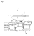
- Fig 1 is a side diagram showing the electronic balance according to one embodiment of the present invention
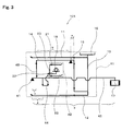
- Fig 2 is a diagram schematically showing the configuration of the electronic balance shown in Fig 1 .
- the connection mechanism is formed of only a connection member for linking the first beam and the second beam.
- An electronic balance 1 is provided with: a first beam 14 which is formed of a main Roberval mechanism R1 for conveying the load of the object to be scaled W in the vertical direction and a first pole which is supported by a first fulcrum 15 so as to be able to sway, and where the main Roberval mechanism R1 is connected to one end portion on the side close to the first fulcrum of the first pole (near distance point) and a second beam (beam at the final stage) 42 is connected to the other end portion on the side far away from the first fulcrum (far distance point) via the connection member 43; a second beam 42 which is formed of a second pole supported by the second fulcrum 41 so as to be able to sway, and where the first beam 14 is connected to one end portion on the side close to the second fulcrum 41 of the second pole (near distance point) via the connection member 43 as described above, and the electromagnetic force generating apparatus 17 is connected to the other end portion on the side far away from the second fulc
- the main Roberval mechanism R1 conveys the load of the object to be scaled W in the vertical direction and has an upper beam 11, a lower beam 12 and a movable portion 13 for linking the upper beam 11 and the lower beam 12. Furthermore, a scale 16 on which the object to be scaled W is placed is provided in an upper portion of the movable portion 13.
- the first beam 14 is formed of a pole which is able to sway with the first fulcrum 15 at the center.
- the movable portion 13 in the main Roberval mechanism R1 is connected to one end portion (near distance point) of the first beam 14, and at the same time, the second beam is connected to the other end portion (far distance point) of the first beam 14 via the connection member 43. Therefore, the load of the object to be scaled W placed on the scale 16 is conveyed to the first beam 14 via the main Roberval mechanism R1, and thus, the displacement of the first beam 14 is conveyed to the second beam 42 via the connection member 43.
- the ratio (a:b) of the length (a) of the first beam 14 on the movable portion 13 side to the length (b) of the first beam 14 on the connection member 43 side with the first fulcrum 15 of the first beam 14 as a reference is a lever ratio.
- the second beam 42 is provided so as to be able to sway with the second fulcrum 41 at the center.
- the first beam 14 is connected to one end portion of the second beam 42 (near distance point) via the connection member 43, and at the same time, the electromagnetic force generating apparatus 17 is provided to the other end portion of the second beam 42 (far distance point). Therefore, the displacement of the first beam 14 is conveyed to the second beam 42 via the connection member 43, and thus, the second beam 42 is displaced.
- the first beam 14 is connected to the second beam 42 on the side opposite to the electromagnetic force generating apparatus 17 side relative to the second fulcrum 41.
- the load of the object to be scaled W placed on the scale 16 is conveyed for the downward displacement on the electromagnetic force generating apparatus 17 side of the second beam 42 relative to the second fulcrum 41. That is to say, the direction in which the load of the object to be scaled W placed on the scale 16 is conveyed to the electromagnetic force generating apparatus 17 and the direction in which the load of the below described incorporated weight 18 is conveyed to the electromagnetic force generating apparatus 17 can be made the same when the load is conveyed to the electromagnetic force generating apparatus 17.
- the ratio (c:e) of the length (c) of the second beam 42 on the connection member 43 side to the length (e) of the second beam 42 on the electromagnetic force generating apparatus 17 side with the second fulcrum 41 of the second beam 42 as a reference is a lever ratio.
- the electromagnetic force generating apparatus 17 generates electromagnetic force which is balance with the applied load.
- An example is a force coil provided in a static magnetic field created by a magnetic circuit so as to be movable, and thus, electromagnetic force for balancing the second beam 42 can be generated by making a current flow through the force coil. Therefore, the load of the object to be scaled W can be measured as an electrical amount by measuring the current value required to balance the second beam.
- the sub-Roberval mechanism R2 conveys the load of the incorporated weight 18 in the vertical direction and has an upper beam 21, a lower beam 22 and a movable portion 23 for linking the upper beam and the lower beam 22. Furthermore, the movable portion 23 is provided with an engaging portion 32 for carrying the incorporated weight 18.
- the incorporated weight 18 is supported by a hoisting apparatus (not shown) at the time of conventional weighing, and thus, the load of the incorporated weight 18 is prevented from being applied to the engaging portion 32. Meanwhile, the incorporated weight 18 is not supported by the hoisting apparatus (not shown) at the time of correction, and thus, the load of the incorporated weight 18 is applied to the engaging portion 32.
- the movable portion 23 of the sub-Roberval mechanism R2 is connected to one end portion of the linking member 44, and at the same time, the second beam 42 is connected to the other end portion of the linking member 44. Therefore, the load of the incorporated weight 18 is conveyed to the second beam 42 via the sub-Roberval mechanism R2.
- the linking member 44 is connected to the second beam 42 on the electromagnetic force generating apparatus 17 side of the second fulcrum 41. That is to say, the ratio (d:e) of the point (d) where the second beam 42 and the linking member 44 are connected to the length (e) of the second beam 42 on the electromagnetic force generating apparatus 17 side with the second fulcrum 41 of the second beam 42 as a reference is a lever ratio.
- the linking member 44 for conveying the load of the incorporated weight 18 is connected between the second fulcrum 41 and the electromagnetic force generating apparatus 17, and therefore, the incorporated weight 18 can be provided without an extending portion, which is an extension of the first beam 14 on the movable portion 13 side, being provided.
- precise correction can be carried out using the incorporated weight 18 which has a load as light as W ⁇ (a/b) ⁇ (c/d). That is to say, a reduction in weight and in size of the electronic balance 1 can both be achieved.
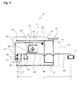
- Fig 3 is a diagram schematically showing the configuration of the electronic balance according to another embodiment of the present invention.
- the present embodiment is different from the above described first embodiment and has a configuration where the load of the incorporated weight is conveyed to the sub-Roberval mechanism when the load of the object to be measured is scaled, and at the same time, the load of the incorporated weight is not conveyed to the sub-Roberval mechanism at the time of correction.
- the same symbols are attached to the same components as in the above described first embodiment, and the descriptions are not repeated.
- the electronic balance 101 is provided with: a main Roberval mechanism R1 for conveying the load of an object to be scaled W in the vertical direction; a first beam 14 which is formed of a first pole supported by the first fulcrum 15 so as to be able to sway and where the main Roberval mechanism R1 is connected to one end portion of the first pole on the side close to the first fulcrum 15 (near distance point), and at the same time, the second beam 42 is connected to the other end portion on the side far away from the first fulcrum 15 (far distance point) via the connection member 43; a second beam 42 which is formed of a second pole supported by the second fulcrum 41 so as to be able to sway and where the first beam 14 is connected to one point on the side close to the second fulcrum 41 (near distance point) via the connection member 43 as described above, and at the same time, the electromagnetic force generating apparatus 17 is connected to one point on the side far away from the second fulcrum 41 (far distance point); an electromagnetic
- the second beam 42 is provided so as to be able to sway with the second fulcrum 41 located in an end portion at the center.
- the first beam 14 is connected to the second beam 42 via the connection member 43, and at the same time, an electromagnetic force generating apparatus 17 is provided in the other end portion of the second beam 42.
- the first beam 14 is connected to the second beam 42 on the electromagnetic force generating apparatus 17 side of the second fulcrum 41.
- the sub-Roberval mechanism R2 conveys the load of the incorporated weigh 18 in the vertical direction and has an upper beam 21, a lower beam 22 and a movable portion 23 for linking the upper beam 21 and the lower beam 22.
- the incorporated weight 18 is supported by a hoisting apparatus (not shown) at the time of correction, and thus, the load of the incorporated weight 18 is not applied to the engaging portion 32.
- the incorporated weight 18 is not supported by the hoisting apparatus (not shown), and thus, the load of the incorporated weight 18 is applied to the engaging portion 32.
- the direction in which the load of the object to be scaled W placed on the scale 16 is conveyed to the electromagnetic force generating apparatus 17 and the direction in which the load of the incorporated weight 18 is not conveyed to the electromagnetic force generating apparatus 17 can be made the same when the load is conveyed to the electromagnetic force generating apparatus 17. Therefore, in comparison with the case where the load is conveyed to the electromagnetic force generating apparatus so that the directions of force become opposite, the width of the intensity of the electromagnetic force which is required to maintain the balance of the second beam 42 in the electromagnetic force generating apparatus 17 can be narrowed.
- the linking member 44 for conveying the load of the incorporated weight 18 is connected between the second fulcrum 41 and the electromagnetic force generating apparatus 17, and therefore, the incorporated weight 18 can be provided without an extending portion, which is the extension of the first beam 14 on the movable portion 13 side, being provided.
- precise correction can be carried out using the incorporated weight 18 having a load as light as W ⁇ (a/b) ⁇ (c/d). That is to say, a reduction in the weight and in the scale of the electronic balance 101 can both be achieved.
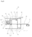
- Fig 4 is a diagram schematically showing the configuration of the electronic balance according to still another embodiment of the present invention.
- a middle beam 46 is added between the first beam and the second beam in series with the structure shown in Fig 2 being a base. That is to say, an electronic balance 2 is provided with: a main Roberval mechanism R1 for conveying the load of an object to be scaled W in the vertical direction; a first beam 14 which is supported by the first fulcrum 15 so as to be able to sway and where the main Roberval mechanism R1 is connected to one end portion on the side close to the first fulcrum (near distance point), and at the same time, the middle beam 46 is connected to the other end portion on the side far away from the first fulcrum (far distance point) via a connection member 43; a middle beam 46 which is formed so as to be able to sway due to a middle fulcrum 47 and where the first beam 14 is connected to one end portion on the side close to the middle fulcrum 47 (n
- the main Roberval mechanism R1 conveys the load of the object to be scaled W in the vertical direction and has an upper beam 11, a lower beam 12 and a movable portion 13 for linking the upper beam 11 and the lower beam 12. Furthermore, a scale 16 on which an object to be scaled W is places is provided in the upper portion of the movable portion 13.
- the first beam 14 is provided so as to be able to sway with the first fulcrum 15 at the center.
- the movable portion 13 of the main Roberval mechanism R1 is connected to one end portion of the first beam 14, and at the same time, the middle beam 46 is connected to the other end portion of the first beam 14 via the connection member 43. Therefore, the load of the object to be scaled W placed on the scale 16 is conveyed to the first beam 14 via the main Roberval mechanism R1, and thus, the displacement of the first beam 14 is conveyed to the middle beam 46 via the connection member 43.
- the ratio (a:b) of the length (a) of the first beam 14 on the movable portion 13 side to the length (b) of the first beam 14 on the connection member 43 side with the first fulcrum 15 of the first beam 14 as a reference is a lever ratio.
- the middle beam 46 is provided so as to be able to sway with the middle fulcrum 47 at the center.
- the first beam 14 is connected to one end portion of the middle beam 46 via the connection member 43, and at the same time, the second beam 42 is connected to the other end portion of the middle beam 46 via the connection member 48.
- the ratio (f:g) of the length (f) of the middle beam 46 on the near distance point side to the length (g) on the far distance point side with the middle fulcrum 47 of the middle beam 46 as a reference is a lever ratio.
- the second beam 42 is provided so as to be able to sway with the second fulcrum 41 located in an end portion of the pole at the center.
- the middle beam 46 is connected to one point on the second beam 42 (near distance point) via the connection member 48, and at the same time, the electromagnetic force generating apparatus 17 is provided at a point on the second beam 42 (far distance point). Therefore, the displacement of the first beam 14 is conveyed to the second beam 42 via the connection member 43 and the middle beam 46, and thus, the second beam 42 is displaced.
- the second fulcrum 41 is located in an end portion, and therefore, the middle beam 46 is connected to the second beam 42 on the same side as the electromagnetic force generating apparatus 17 side relative to the second fulcrum 41.
- the load of the object to be scaled W placed on the scale 16 is conveyed as the downward displacement on the electromagnetic force generating apparatus 17 side of the second fulcrum 41 of the second beam 42. That is to say, the direction in which the load of the object to be scaled W placed on the scale 16 is conveyed to the electromagnetic force generating apparatus 17 and the direction in which the load of the below described incorporated weight 18 is conveyed to the electromagnetic force generating apparatus 17 can be made the same when the load is conveyed to the electromagnetic force generating apparatus 17.
- the ratio (c:e) of the length (c) of the second beam 42 on the connection member 43 side to the length (e) of the second beam 42 on the electromagnetic force generating apparatus 17 side with the second fulcrum 41 of the second beam 42 as a reference is a lever ration.
- the sub-Roberval mechanism R2 conveys the load of the incorporated weight 18 in the vertical direction and has an upper beam 21, a lower beam 22 and a movable portion 23 for linking the upper beam 21 and the lower beam 22. Furthermore, an engaging portion 32 for carrying the incorporated weight 18 is provided in the movable portion 23.
- the incorporated weight 18 is supported by a hoisting apparatus (not shown), and thus, the load of the incorporated weight 18 is not applied to the engaging portion 32. Meanwhile, at the time of correction, the incorporated weight 18 is not supported by a hoisting apparatus (not shown), and thus, the load of the incorporated weight 18 is applied to the engaging portion 32.
- the movable portion 23 of the sub-Roberval mechanism R2 is connected to one end portion of the linking member 44, and at the same time, the second beam 42 is connected to the other end portion of the linking member 44. Therefore, the load of the incorporated weight 18 is conveyed to the second beam 42 via the sub-Roberval mechanism R2.
- the linking member 44 is connected to the second beam 42 on the electromagnetic force generating apparatus 17 side of the second fulcrum 41. That is to say, the ratio (d:e) of the point (d) where the second beam 42 and the linking member 44 are connected to the length (e) of the second beam 42 on the electromagnetic force generating apparatus 17 side with the second fulcrum 41 of the second beam 42 as a reference is a lever ratio.
- the linking member 44 for conveying the load of the incorporated weight 18 is connected between the second fulcrum 41 and the electromagnetic force generating apparatus 17, and therefore, the incorporated weight 18 can be provided without an extending portion, which is an extension of the first beam 14 on the movable portion 13 side, being provided.
- precise correction can be carried out using the incorporated weight 18 which has a load of W ⁇ (a/b) ⁇ (f/g) ⁇ (c/d) and is lighter than that in Fig 2 . That is to say, a reduction in the weight and in the scale of the electronic balance 1 can further be achieved.
- one middle beam 46 is provided between the first beam 14 and the second beam 42
- an additional middle beam may be connected in series between the middle beam 46 and the second beam 42 so that the attenuation ratio can further be increased.
- the electronic balance according to the present invention can be formed for use so that precise correction can be carried out by using incorporated weight, for example.
Landscapes
- Physics & Mathematics (AREA)
- General Physics & Mathematics (AREA)
- Measurement Of Force In General (AREA)
- Weight Measurement For Supplying Or Discharging Of Specified Amounts Of Material (AREA)
Abstract
Description
- The present invention relates to an electronic balance, and in particular, to an electronic balance which is formed so that precise correction can be carried out with an incorporated weight.
- Analytical balances with which an extremely light object of approximately 1 µg can be measured have been proposed as electronic balances, and large scale balances with which an extremely heavy object of several tens of kg can be measured have also been proposed. In these electronic balances, a change in the temperature, for example, causes a change in the electromagnetic force, which is scaled with the load of the object to be weighed, or a slight expansion or contraction of the load conveying mechanism. As a result, there is an error in the results of the measurement of the load of the object to be weighed. Therefore, it is necessary to correct the electronic balance using weight for correction in order to prevent errors from being caused in the results of measurement of the load of the object to be weighed.
- Thus, in the case where correction is carried out using weight for correction, it is necessary to pay attention to the handling and maintenance of the weight for correction, and therefore, there are weight incorporated type electronic balances where weight for correction has been installed in advance within an electronic balance (for example, see Patent Document 1). In these weight incorporated type electronic balances, appropriate correction is carried out through the operation of the buttons by the operator, or automatic correction is carried out through signals from a timer, a temperature sensor and the like.
-
Fig 5 is a diagram schematically showing the configuration of a conventional weight incorporated type electronic balance. In anelectronic balance 60, anupper beam 50, alower bean 51 and amovable portion 52 for connecting theupper beam 50 and thelower beam 51 form a main Roberval mechanism R1 for conveying the load of the object to be weighed W which is applied to ascale 56 in the vertical direction, and abeam 54 which is connected to themovable portion 52 of the main Roberval mechanism R1 is provided so as to be able to sway with afulcrum 55 at the center. Furthermore, an electromagneticforce generating apparatus 57 is provided to thebeam 54 on the side opposite to themovable portion 52 side. As a result, the load of the object to be weighed W which is applied to thescale 56 is conveyed to thebeam 54 via the main Roberval mechanism R1, and thus, an electromagnetic force required to keep thebeam 54 balanced is generated in the electromagneticforce generating apparatus 57. Accordingly, the current value which is required to generate the electromagnetic force at this time is measured so that the load of the object to be weighed W can be measured as the amount of electricity. At this time, the ratio of the length (g) of thebeam 54 on themovable portion 52 side to the length (f) of thebeam 54 on the electromagneticforce generating apparatus 57 side with thefulcrum 55 of thebeam 54 as a reference becomes the leverage.
In thiselectronic balance 60, correction is carried out using incorporatedweight 58, and therefore, anengaging portion 62a is provided in themovable portion 52 and the load of the incorporatedweight 58 can be conveyed to theengaging portion 62a in the configuration. -
Fig 6 shows an example of a conventional electronic balance where the size of incorporated weight is reduced, and in theelectronic balance 160, correction is carried out using light incorporatedweight 58, and therefore, anextension portion 54a which extends from themovable portion 52 side of thebeam 54 is provided, and at the same time, themovable portion 61 of a sub-Roberval mechanism R2 is connected to theextension portion 54a. Here, the same symbols are attached to the same components as in the above describedelectronic balance 60, and the descriptions thereof are omitted.
Anupper beam 63 and alower beam 64 are connected to the top and the bottom of themovable portion 61, and thus, the sub-Roberval mechanism R2 is formed. In addition, anengaging portion 62b on which incorporatedweight 58 is placed is provided in themovable portion 61. At this time, the ration (h:f) of the length (h) of thebeam 54 on themovable portion 61 side and the length (f) of thebeam 54 on the electromagneticforce generating apparatus 57 side with thefulcrum 55 of thebeam 54 as a reference becomes the leverage. Accordingly, the point where themovable portion 61 to which the load of the incorporatedweight 58 is applied and thebeam 54 are connected is moved away from thefulcrum 55 of thebeam 54, that is to say, the length (h) of thebeam 54 on themovable portion 61 side is increased, and thus, correction can be carried out with a relatively light incorporatedweight 58. - Here, in order to carry out precise correction, it is desirable for the electromagnetic force to be generated in the electromagnetic
force generating apparatus 57 so that the object to be weighed W is in a state which is actually measured using incorporatedweight 58. However, in large scale balances with which an extremely heavy object to be weighed W of several tens of kg is measured, in the case where incorporatedweight 58, which is sufficient for the object to be weighed W, is contained, it increases the weight of theelectronic balance beam 54 on themovable portion 61 side is increased in order to use the relatively light incorporatedweight 58, various problems arise such that the volume of theelectronic balance 160 increases. - Thus, incorporated weight type electronic balances having first and second beams are disclosed.
Fig 7 is a side diagram showing another conventional weight incorporated type electronic balance, andFig 8 is a diagram schematically showing the configuration of the electronic balance shown inFig 7 . Theelectronic balance 80 is provided with a main Roberval mechanism R1 for conveying the load of the object to be weighed W which is applied to ascale 76 in the vertical direction, afirst beam 74, which is formed so as to be able to sway by means of afulcrum 75 and of which one end is connected to a movable portion of the main Roberval mechanism R1 and of which the other end is connected to asecond beam 92 via aconnection member 93, an electromagneticforce generating apparatus 77, incorporatedweight 78 for correction, a sub-Roberval mechanism R2 for conveying the load of the incorporatedweight 78 in the vertical direction and asecond beam 92 of which one end is connected to amovable portion 81 of the sub-Roberval mechanism R2 and of which the other end is connected to the electromagneticforce generating apparatus 77. As a result, the ratio (j:i) of the length (j) of thefirst beam 74 on the movable portion side to the length (i) of thefirst beam 74 on theconnection member 93 side with afulcrum 75 of thefirst beam 74 as a reference becomes the leverage, and at the same time, the ratio (k:m) of the point (k) at which theconnection member 93 and thesecond beam 92 are connected to the length (m) of thesecond beam 92 on the electromagneticforce generating apparatus 77 side with afulcrum 91 of thesecond beam 92 as a reference becomes the leverage. - In this
electronic balance 80 also, correction is carried out using incorporatedweight 78, and therefore, anextension portion 92a which extends from thesecond beam 92 on the side opposite to the electromagneticforce generating apparatus 77 side is provided, and at the same time, amovable portion 81 of the sub-Roberval mechanism R2 is connected to theextension section 92a. Here, anupper beam 83 and alower beam 84 are connected to the top and the bottom of themovable portion 81, and thus, a sub-Roberval mechanism R2 for conveying the load of the incorporatedweight 78 in the vertical direction is formed. At this time, the ratio (1:m) of the length (1) of thesecond beam 92 on themovable portion 81 side to the length (m) of thesecond beam 92 on the electromagneticforce generating apparatus 77 side with afulcrum 91 of thesecond beam 92 as a reference becomes the leverage. Accordingly, the point where themovable portion 81 to which the load of the incorporatedweight 78 is applied and thesecond beam 92 are connected is moved away from thefulcrum 91 of thesecond beam 92, that is to say, the length (1) of thesecond beam 92 on themovable portion 81 side is increased so that correction can be carried out with a relatively light incorporatedweight 78. - Patent Document 1: Japanese Patent No.
3645372 - The further the point where the
movable portion weight beam 54 or thesecond beam 92 are connected is away from thefulcrum beam 54 or thesecond beam 92, the lighter the incorporatedweight beam 54 or thesecond beam 92 becomes. Meanwhile, the shorter the length of thebeam 54 or thesecond beam 92 is, the closer the point where themovable portion weight beam 54 or thesecond beam 92 are connected becomes to thefulcrum beam 54 or thesecond beam 92, and therefore, the weight of the incorporatedweight - Thus, an object of the present invention is to provide an electronic balance where precise correction can be carried out by using incorporated weight and the weight and the size can both be reduced.
- In order to solve the above described problem, the electronic balance according to the present invention is provided with: a scale; a main Roberval mechanism for conveying the load of an object to be measured which is mounted on the scale in the vertical direction; a first beam made up of a first pole which is supported by a first fulcrum so as to be able to sway, where the main Roberval mechanism is connected to the near distance point and a connection means for conveying the load of the object to be measured is connected to the far distance point, the near distance point being a distance point close to the first fulcrum on the first pole and the far distance point being a distance point far away from the first fulcrum; a second beam made up of a second pole which is supported by a second fulcrum so as to be able to sway, where the first beam is connected to a near distance point via a connection means and an electromagnetic force generating apparatus for generating an electromagnetic force that is balanced with the load of the object to be measured which is conveyed from the first beam is connected to a far distance point, the near distance point being a distance point close to the second fulcrum on the second pole and the far distance point being a distance point far away from the second fulcrum; incorporated weight for correction; a sub-Roberval mechanism for conveying the load of the above described incorporated weight in the vertical direction; a linking member for conveying the load of the above described incorporated weight to the second beam via the above described sub-Roberval mechanism; and an electromagnetic force generating apparatus for generating an electromagnetic force that is balanced with the load of the object to be measured, and the above described linking member is connected to the above described second beam on the electromagnetic force generating apparatus side relative to the second fulcrum.
- Here, "connection means" links the first beam to the second beam and conveys the load of the object to be measured that is conveyed from the scale through the first beam (here, the size of the load attenuates in accordance with the leverage of the first beam) to the second beam, and concretely, may be formed of only one connection member which can convey the load of the object to be measured at the far distance point in the first beam as it is, or may make the load of the object to be measured at the far distance point in the first beam attenuate by intervening a more mechanical load conveying mechanism (for example, middle beams) and then convey the load of the object to be measured to the second beam.
- In the electronic balance according to the present invention, the linking member for conveying the load of the incorporated weight is connected between the second fulcrum of the second beam and the electromagnetic force generating apparatus, and therefore, the incorporated weight can be provided without an extending portion being provided where the first beam is extended. In addition, correction can be carried out with a small and lightweight incorporated weight. That is to say, a reduction in the weight and a miniaturization of the electronic balance can both be achieved.
- In the above invention, the connection means may include at least one middle beam made up of a pole of which the two ends are connected to the first beam and the second beam via connection members in series, each middle beam is supported by a middle fulcrum in the middle beam so as to be able to sway, and a near distance point of each middle beam is connected to the connection member on the first beam side and a far distance point of each middle beam is connected to the connection member on the second beam side, the near distance point being a distance point close to the middle fulcrum of the middle beam and the far distance point being a distance point far away from the middle fulcrum.
As a result, the load of the object to be measured which is conveyed from the first beam is reduced before being conveyed to the second beam in accordance with the lever ratio of the middle beam provided between the first beam and the second beam (in the case where a number of middle beams are connected in series, the product of the lever ratios), and therefore, the incorporated weight for correction can be further reduced. - In addition, in the above respective inventions, the load of the above described incorporated weight may be conveyed to the above described sub-Roberval mechanism when the load of the above described object to be measured is weighed, and at the same time, the load of the above described incorporated weight need not to be conveyed to the above described sub-Roberval mechanism at the time of correction.
As a result, in the case of a structure where the direction of the force when the load of the object to be scaled mounted on the scale is conveyed to the electromagnetic force generating apparatus and the direction in which the force is conveyed to the electromagnetic force generating apparatus by the load when the incorporated weight is mounted on the sub-Roberval mechanism (that is to say, increased load on the sub-Roberval mechanism) are in opposite directions, the load is removed from the sub-Roberval mechanism (that is to say, the load applied to the sub-Roberval mechanism in advance is reduced) at the time of correction, and thus, the direction of the force can be made the same so that the force can be conveyed to the electromagnetic force generating apparatus. Therefore, compared to the case where the direction of the force becomes a different direction when the force is conveyed to the electromagnetic force generating apparatus, the width of the intensity of the electromagnetic force which is required to maintain the balance of the second beam in the electromagnetic force generating apparatus can be narrowed in the configuration. -
-
Fig 1 is a side diagram showing the electronic balance according to one embodiment of the present invention; -
Fig 2 is a diagram schematically showing the configuration of the electronic balance shown inFig 1 ; -
Fig 3 is a diagram schematically showing the configuration of the electronic balance according to another embodiment of the present invention; -
Fig 4 is a diagram schematically showing the configuration of the electronic balance according to still another embodiment of the present invention; -
Fig 5 is a diagram schematically showing the configuration of a conventional incorporated weight type electronic balance; -
Fig 6 is a diagram schematically showing the configuration of another conventional incorporated weight type electronic balance; -
Fig 7 is a side diagram showing another conventional incorporated weight type electronic balance; and -
Fig 8 is a diagram schematically showing the configuration of the electronic balance shown inFig 7 . -
- 1, 2, 101
- electronic balance
- 14
- first beam
- 15
- first fulcrum
- 41
- second fulcrum
- 17
- electromagnetic force generating apparatus
- 18
- incorporated weight
- 42
- second beam
- 43
- connection member
- 44
- linking member
- 46
- middle beam
- 47
- middle fulcrum
- 48
- connection member
- In the following, the embodiments of the present invention are described in reference to the drawings. Here, the present invention is not limited to the below described embodiments, and, of course, includes various embodiments in a range without deviating from the gist of the present invention.
-
Fig 1 is a side diagram showing the electronic balance according to one embodiment of the present invention, andFig 2 is a diagram schematically showing the configuration of the electronic balance shown inFig 1 . In the present embodiment, the connection mechanism is formed of only a connection member for linking the first beam and the second beam.
An electronic balance 1 is provided with: a first beam 14 which is formed of a main Roberval mechanism R1 for conveying the load of the object to be scaled W in the vertical direction and a first pole which is supported by a first fulcrum 15 so as to be able to sway, and where the main Roberval mechanism R1 is connected to one end portion on the side close to the first fulcrum of the first pole (near distance point) and a second beam (beam at the final stage) 42 is connected to the other end portion on the side far away from the first fulcrum (far distance point) via the connection member 43; a second beam 42 which is formed of a second pole supported by the second fulcrum 41 so as to be able to sway, and where the first beam 14 is connected to one end portion on the side close to the second fulcrum 41 of the second pole (near distance point) via the connection member 43 as described above, and the electromagnetic force generating apparatus 17 is connected to the other end portion on the side far away from the second fulcrum 41 (far distance point); an electromagnetic force generating apparatus 17 for generating electromagnetic force which is balanced with the upright load; incorporated weight 18 for correction; a sub-Roberval mechanism R2 for conveying the load of the incorporated weight 18 in the vertical direction; and a linking member 44 where the sub-Roberval mechanism R2 is connected to one end portion and the second beam 42 is connected to the other end portion. - The main Roberval mechanism R1 conveys the load of the object to be scaled W in the vertical direction and has an
upper beam 11, alower beam 12 and amovable portion 13 for linking theupper beam 11 and thelower beam 12. Furthermore, ascale 16 on which the object to be scaled W is placed is provided in an upper portion of themovable portion 13. - The
first beam 14 is formed of a pole which is able to sway with thefirst fulcrum 15 at the center. In addition, themovable portion 13 in the main Roberval mechanism R1 is connected to one end portion (near distance point) of thefirst beam 14, and at the same time, the second beam is connected to the other end portion (far distance point) of thefirst beam 14 via theconnection member 43. Therefore, the load of the object to be scaled W placed on thescale 16 is conveyed to thefirst beam 14 via the main Roberval mechanism R1, and thus, the displacement of thefirst beam 14 is conveyed to thesecond beam 42 via theconnection member 43. At this time, the ratio (a:b) of the length (a) of thefirst beam 14 on themovable portion 13 side to the length (b) of thefirst beam 14 on theconnection member 43 side with thefirst fulcrum 15 of thefirst beam 14 as a reference is a lever ratio. - The
second beam 42 is provided so as to be able to sway with thesecond fulcrum 41 at the center. In addition, thefirst beam 14 is connected to one end portion of the second beam 42 (near distance point) via theconnection member 43, and at the same time, the electromagneticforce generating apparatus 17 is provided to the other end portion of the second beam 42 (far distance point). Therefore, the displacement of thefirst beam 14 is conveyed to thesecond beam 42 via theconnection member 43, and thus, thesecond beam 42 is displaced. Here, thefirst beam 14 is connected to thesecond beam 42 on the side opposite to the electromagneticforce generating apparatus 17 side relative to thesecond fulcrum 41. As a result, the load of the object to be scaled W placed on thescale 16 is conveyed for the downward displacement on the electromagneticforce generating apparatus 17 side of thesecond beam 42 relative to thesecond fulcrum 41. That is to say, the direction in which the load of the object to be scaled W placed on thescale 16 is conveyed to the electromagneticforce generating apparatus 17 and the direction in which the load of the below described incorporatedweight 18 is conveyed to the electromagneticforce generating apparatus 17 can be made the same when the load is conveyed to the electromagneticforce generating apparatus 17. Therefore, as for the electromagnetic force required to maintain the balance of thesecond beam 42 in the electromagneticforce generating apparatus 17, only the electromagnetic force in the direction toward one side needs to be taken into consideration, and thus, the width of the intensity of the electromagnetic force can be narrowed.
Here, the ratio (c:e) of the length (c) of thesecond beam 42 on theconnection member 43 side to the length (e) of thesecond beam 42 on the electromagneticforce generating apparatus 17 side with thesecond fulcrum 41 of thesecond beam 42 as a reference is a lever ratio. - The electromagnetic
force generating apparatus 17 generates electromagnetic force which is balance with the applied load. An example is a force coil provided in a static magnetic field created by a magnetic circuit so as to be movable, and thus, electromagnetic force for balancing thesecond beam 42 can be generated by making a current flow through the force coil. Therefore, the load of the object to be scaled W can be measured as an electrical amount by measuring the current value required to balance the second beam. - The sub-Roberval mechanism R2 conveys the load of the incorporated
weight 18 in the vertical direction and has anupper beam 21, alower beam 22 and amovable portion 23 for linking the upper beam and thelower beam 22. Furthermore, themovable portion 23 is provided with an engagingportion 32 for carrying the incorporatedweight 18. Here, the incorporatedweight 18 is supported by a hoisting apparatus (not shown) at the time of conventional weighing, and thus, the load of the incorporatedweight 18 is prevented from being applied to the engagingportion 32. Meanwhile, the incorporatedweight 18 is not supported by the hoisting apparatus (not shown) at the time of correction, and thus, the load of the incorporatedweight 18 is applied to the engagingportion 32. - The
movable portion 23 of the sub-Roberval mechanism R2 is connected to one end portion of the linkingmember 44, and at the same time, thesecond beam 42 is connected to the other end portion of the linkingmember 44. Therefore, the load of the incorporatedweight 18 is conveyed to thesecond beam 42 via the sub-Roberval mechanism R2. At this time, the linkingmember 44 is connected to thesecond beam 42 on the electromagneticforce generating apparatus 17 side of thesecond fulcrum 41. That is to say, the ratio (d:e) of the point (d) where thesecond beam 42 and the linkingmember 44 are connected to the length (e) of thesecond beam 42 on the electromagneticforce generating apparatus 17 side with thesecond fulcrum 41 of thesecond beam 42 as a reference is a lever ratio. - As described above, in the
electronic balance 1, the linkingmember 44 for conveying the load of the incorporatedweight 18 is connected between thesecond fulcrum 41 and the electromagneticforce generating apparatus 17, and therefore, the incorporatedweight 18 can be provided without an extending portion, which is an extension of thefirst beam 14 on themovable portion 13 side, being provided. In addition, precise correction can be carried out using the incorporatedweight 18 which has a load as light as W × (a/b) × (c/d). That is to say, a reduction in weight and in size of theelectronic balance 1 can both be achieved. -
Fig 3 is a diagram schematically showing the configuration of the electronic balance according to another embodiment of the present invention. The present embodiment is different from the above described first embodiment and has a configuration where the load of the incorporated weight is conveyed to the sub-Roberval mechanism when the load of the object to be measured is scaled, and at the same time, the load of the incorporated weight is not conveyed to the sub-Roberval mechanism at the time of correction. Here, the same symbols are attached to the same components as in the above described first embodiment, and the descriptions are not repeated. - The electronic balance 101 is provided with: a main Roberval mechanism R1 for conveying the load of an object to be scaled W in the vertical direction; a first beam 14 which is formed of a first pole supported by the first fulcrum 15 so as to be able to sway and where the main Roberval mechanism R1 is connected to one end portion of the first pole on the side close to the first fulcrum 15 (near distance point), and at the same time, the second beam 42 is connected to the other end portion on the side far away from the first fulcrum 15 (far distance point) via the connection member 43; a second beam 42 which is formed of a second pole supported by the second fulcrum 41 so as to be able to sway and where the first beam 14 is connected to one point on the side close to the second fulcrum 41 (near distance point) via the connection member 43 as described above, and at the same time, the electromagnetic force generating apparatus 17 is connected to one point on the side far away from the second fulcrum 41 (far distance point); an electromagnetic force generating apparatus 17 for generating electromagnetic force which is balanced with the applied load; incorporated weight 18 for correction; a sub-Roberval mechanism R2 for conveying the load of the incorporated weight 18 in the vertical direction; and a linking member 44 where the sub-Roberval mechanism R2 is connected to one end portion, and at the same time, the second beam 42 is connected to the other end portion.
- The
second beam 42 is provided so as to be able to sway with thesecond fulcrum 41 located in an end portion at the center. In addition, thefirst beam 14 is connected to thesecond beam 42 via theconnection member 43, and at the same time, an electromagneticforce generating apparatus 17 is provided in the other end portion of thesecond beam 42. At this time, unlike the above described first embodiment, thefirst beam 14 is connected to thesecond beam 42 on the electromagneticforce generating apparatus 17 side of thesecond fulcrum 41. - The sub-Roberval mechanism R2 conveys the load of the incorporated weigh 18 in the vertical direction and has an
upper beam 21, alower beam 22 and amovable portion 23 for linking theupper beam 21 and thelower beam 22. Here, unlike the above described first embodiment, the incorporatedweight 18 is supported by a hoisting apparatus (not shown) at the time of correction, and thus, the load of the incorporatedweight 18 is not applied to the engagingportion 32. Meanwhile, at the time of conventional weighing, the incorporatedweight 18 is not supported by the hoisting apparatus (not shown), and thus, the load of the incorporatedweight 18 is applied to the engagingportion 32. That is to say, the direction in which the load of the object to be scaled W placed on thescale 16 is conveyed to the electromagneticforce generating apparatus 17 and the direction in which the load of the incorporatedweight 18 is not conveyed to the electromagneticforce generating apparatus 17 can be made the same when the load is conveyed to the electromagneticforce generating apparatus 17. Therefore, in comparison with the case where the load is conveyed to the electromagnetic force generating apparatus so that the directions of force become opposite, the width of the intensity of the electromagnetic force which is required to maintain the balance of thesecond beam 42 in the electromagneticforce generating apparatus 17 can be narrowed. - As described above, in the
electronic balance 101, the linkingmember 44 for conveying the load of the incorporatedweight 18 is connected between thesecond fulcrum 41 and the electromagneticforce generating apparatus 17, and therefore, the incorporatedweight 18 can be provided without an extending portion, which is the extension of thefirst beam 14 on themovable portion 13 side, being provided. In addition, precise correction can be carried out using the incorporatedweight 18 having a load as light as W × (a/b) × (c/d). That is to say, a reduction in the weight and in the scale of theelectronic balance 101 can both be achieved. -
Fig 4 is a diagram schematically showing the configuration of the electronic balance according to still another embodiment of the present invention.
In the present embodiment, amiddle beam 46 is added between the first beam and the second beam in series with the structure shown inFig 2 being a base.
That is to say, an electronic balance 2 is provided with: a main Roberval mechanism R1 for conveying the load of an object to be scaled W in the vertical direction; a first beam 14 which is supported by the first fulcrum 15 so as to be able to sway and where the main Roberval mechanism R1 is connected to one end portion on the side close to the first fulcrum (near distance point), and at the same time, the middle beam 46 is connected to the other end portion on the side far away from the first fulcrum (far distance point) via a connection member 43; a middle beam 46 which is formed so as to be able to sway due to a middle fulcrum 47 and where the first beam 14 is connected to one end portion on the side close to the middle fulcrum 47 (near distance point) via the connection member 43 as described above and the second beam 42 is connected to the other end portion on the side far away from the middle fulcrum 47 (far distance point) via the connection member 48; a second beam 42 which is formed so as to be able to sway due to a second fulcrum 41 located in an end portion and where the middle beam 46 is connected to one point on the side close to the second fulcrum 41 (near distance point) via the connection member 48 as described above and an electromagnetic force generating apparatus 17 is connected to one point on the side far away from the second fulcrum 41 (far distance point); an electromagnetic force generating apparatus 17 for generating electromagnetic force which is balanced with the applied load; incorporated weight 18 for correction; a sub-Roberval mechanism R2 for conveying the load of the incorporated weight 18 in the vertical direction; and a linking member 44 where the sub-Roberval mechanism R2 is connected to one end portion, and at the same time, the second beam 42 is connected to the other end portion. - The main Roberval mechanism R1 conveys the load of the object to be scaled W in the vertical direction and has an
upper beam 11, alower beam 12 and amovable portion 13 for linking theupper beam 11 and thelower beam 12. Furthermore, ascale 16 on which an object to be scaled W is places is provided in the upper portion of themovable portion 13. - The
first beam 14 is provided so as to be able to sway with thefirst fulcrum 15 at the center. In addition, themovable portion 13 of the main Roberval mechanism R1 is connected to one end portion of thefirst beam 14, and at the same time, themiddle beam 46 is connected to the other end portion of thefirst beam 14 via theconnection member 43. Therefore, the load of the object to be scaled W placed on thescale 16 is conveyed to thefirst beam 14 via the main Roberval mechanism R1, and thus, the displacement of thefirst beam 14 is conveyed to themiddle beam 46 via theconnection member 43. At this time, the ratio (a:b) of the length (a) of thefirst beam 14 on themovable portion 13 side to the length (b) of thefirst beam 14 on theconnection member 43 side with thefirst fulcrum 15 of thefirst beam 14 as a reference is a lever ratio. - The
middle beam 46 is provided so as to be able to sway with themiddle fulcrum 47 at the center. In addition, thefirst beam 14 is connected to one end portion of themiddle beam 46 via theconnection member 43, and at the same time, thesecond beam 42 is connected to the other end portion of themiddle beam 46 via theconnection member 48. At this time, the ratio (f:g) of the length (f) of themiddle beam 46 on the near distance point side to the length (g) on the far distance point side with themiddle fulcrum 47 of themiddle beam 46 as a reference is a lever ratio. - The
second beam 42 is provided so as to be able to sway with thesecond fulcrum 41 located in an end portion of the pole at the center. In addition, themiddle beam 46 is connected to one point on the second beam 42 (near distance point) via theconnection member 48, and at the same time, the electromagneticforce generating apparatus 17 is provided at a point on the second beam 42 (far distance point). Therefore, the displacement of thefirst beam 14 is conveyed to thesecond beam 42 via theconnection member 43 and themiddle beam 46, and thus, thesecond beam 42 is displaced.
Here, thesecond fulcrum 41 is located in an end portion, and therefore, themiddle beam 46 is connected to thesecond beam 42 on the same side as the electromagneticforce generating apparatus 17 side relative to thesecond fulcrum 41. As a result, the load of the object to be scaled W placed on thescale 16 is conveyed as the downward displacement on the electromagneticforce generating apparatus 17 side of thesecond fulcrum 41 of thesecond beam 42. That is to say, the direction in which the load of the object to be scaled W placed on thescale 16 is conveyed to the electromagneticforce generating apparatus 17 and the direction in which the load of the below described incorporatedweight 18 is conveyed to the electromagneticforce generating apparatus 17 can be made the same when the load is conveyed to the electromagneticforce generating apparatus 17. Therefore, as for the electromagnetic force required to maintain the balance of thesecond beam 42 in the electromagneticforce generating apparatus 17, only the force in the direction toward one side needs to be taken into consideration, and therefore, the width of the intensity of the electromagnetic force can be narrowed.
Here, the ratio (c:e) of the length (c) of thesecond beam 42 on theconnection member 43 side to the length (e) of thesecond beam 42 on the electromagneticforce generating apparatus 17 side with thesecond fulcrum 41 of thesecond beam 42 as a reference is a lever ration. - The sub-Roberval mechanism R2 conveys the load of the incorporated
weight 18 in the vertical direction and has anupper beam 21, alower beam 22 and amovable portion 23 for linking theupper beam 21 and thelower beam 22. Furthermore, an engagingportion 32 for carrying the incorporatedweight 18 is provided in themovable portion 23. Here, at the time of conventional weighing, the incorporatedweight 18 is supported by a hoisting apparatus (not shown), and thus, the load of the incorporatedweight 18 is not applied to the engagingportion 32. Meanwhile, at the time of correction, the incorporatedweight 18 is not supported by a hoisting apparatus (not shown), and thus, the load of the incorporatedweight 18 is applied to the engagingportion 32. - The
movable portion 23 of the sub-Roberval mechanism R2 is connected to one end portion of the linkingmember 44, and at the same time, thesecond beam 42 is connected to the other end portion of the linkingmember 44. Therefore, the load of the incorporatedweight 18 is conveyed to thesecond beam 42 via the sub-Roberval mechanism R2. At this time, the linkingmember 44 is connected to thesecond beam 42 on the electromagneticforce generating apparatus 17 side of thesecond fulcrum 41. That is to say, the ratio (d:e) of the point (d) where thesecond beam 42 and the linkingmember 44 are connected to the length (e) of thesecond beam 42 on the electromagneticforce generating apparatus 17 side with thesecond fulcrum 41 of thesecond beam 42 as a reference is a lever ratio. - As described above, in the
electronic balance 2, the linkingmember 44 for conveying the load of the incorporatedweight 18 is connected between thesecond fulcrum 41 and the electromagneticforce generating apparatus 17, and therefore, the incorporatedweight 18 can be provided without an extending portion, which is an extension of thefirst beam 14 on themovable portion 13 side, being provided. In addition, precise correction can be carried out using the incorporatedweight 18 which has a load of W × (a/b) × (f/g) × (c/d) and is lighter than that inFig 2 . That is to say, a reduction in the weight and in the scale of theelectronic balance 1 can further be achieved. - Though in the present embodiment one
middle beam 46 is provided between thefirst beam 14 and thesecond beam 42, an additional middle beam may be connected in series between themiddle beam 46 and thesecond beam 42 so that the attenuation ratio can further be increased. - The electronic balance according to the present invention can be formed for use so that precise correction can be carried out by using incorporated weight, for example.
Claims (6)
- An electronic balance, comprising:a scale;a main Roberval mechanism for conveying the load of an object to be measured which is mounted on the scale in the vertical direction;a first beam made up of a first pole which is supported by a first fulcrum so as to be able to sway, where the main Roberval mechanism is connected to the near distance point and a connection means for conveying the load of the object to be measured is connected to the far distance point, the near distance point being a distance point close to the first fulcrum on the first pole and the far distance point being a distance point far away from the first fulcrum;a second beam made up of a second pole which is supported by a second fulcrum so as to be able to sway, where the first beam is connected to a near distance point via a connection means and an electromagnetic force generating apparatus for generating an electromagnetic force that is balanced with the load of the object to be measured which is conveyed from the first beam is connected to a far distance point, the near distance point being a distance point close to the second fulcrum on the second pole and the far distance point being a distance point far away from the second fulcrum;incorporated weight for correction;a sub-Roberval mechanism for conveying the load of said incorporated weight in the vertical direction;a linking member for conveying the load of said incorporated weight to the second beam via said sub-Roberval mechanism; andan electromagnetic force generating apparatus for generating an electromagnetic force that is balanced with the load of the object to be measured,characterized in that
said linking member is connected to said second beam on the electromagnetic force generating apparatus side relative to the second fulcrum. - The electronic balance according to Claim 1, characterized in that said connection means includes at least one middle beam made up of a pole of which the two ends are connected to the first beam and the second beam via connection members in series, each middle beam is supported by a middle fulcrum in the middle beam so as to be able to sway, and a near distance point of each middle beam is connected to the connection member on the first beam side and a far distance point of each middle beam is connected to the connection member on the second beam side, the near distance point being a distance point close to the middle fulcrum of the middle beam and the far distance point being a distance point far away from the middle fulcrum.
- The electronic balance according to Claim 1, characterized in that the load of said incorporated weight is conveyed to said sub-Roberval mechanism when the load of said object to be measured is weighed, and at the same time, the load of said incorporated weight is not conveyed to said sub-Roberval mechanism at the time of correction.
- The electronic balance according to Claim 1, characterized in that said connection means is formed of only one connection member.
- The electronic balance according to Claim 4, characterized in that
said second fulcrum is provided between the near distance point and the far distance point in said second beam, a lifting apparatus for not conveying the load of said incorporated weight to said sub-Roberval mechanism when the load of said object to be measured is weighed, and at the same time, conveying the load of said incorporated weight to said sub-Roberval mechanism at the time of correction is provided, and
the direction in which the load of the weight to be weighed mounted on said scale is conveyed to the electromagnetic force generating apparatus, and the direction in which the load of the incorporated weight is conveyed to the electromagnetic force generating apparatus at the time of correction are the same. - The electronic balance according to Claim 4, characterized in that
said near distance point is provided between the second fulcrum and the far distance point in said second beam,
a lifting apparatus for conveying the load of said incorporated weight to said sub-Roberval mechanism when the load of said object to be measured is weighed and not conveying the load of said incorporated weight to said sub-Roberval mechanism at the time of correction is provided, and
the direction in which the load of the object to be measured mounted on said scale is conveyed to the electromagnetic force generating apparatus, and the direction in which the load of the object to be weighed is conveyed to the electromagnetic force generating apparatus at the time of correction due to the load of said incorporated weight not being conveyed are the same.
Applications Claiming Priority (2)
| Application Number | Priority Date | Filing Date | Title |
|---|---|---|---|
| JP2006231423 | 2006-08-29 | ||
| PCT/JP2007/063473 WO2008026378A1 (en) | 2006-08-29 | 2007-07-05 | Electronic balance |
Publications (2)
| Publication Number | Publication Date |
|---|---|
| EP2058635A1 true EP2058635A1 (en) | 2009-05-13 |
| EP2058635A4 EP2058635A4 (en) | 2011-08-31 |
Family
ID=39135665
Family Applications (1)
| Application Number | Title | Priority Date | Filing Date |
|---|---|---|---|
| EP07768222A Withdrawn EP2058635A4 (en) | 2006-08-29 | 2007-07-05 | Electronic balance |
Country Status (5)
| Country | Link |
|---|---|
| US (1) | US8044308B2 (en) |
| EP (1) | EP2058635A4 (en) |
| JP (1) | JP4952717B2 (en) |
| CN (1) | CN101501463B (en) |
| WO (1) | WO2008026378A1 (en) |
Families Citing this family (12)
| Publication number | Priority date | Publication date | Assignee | Title |
|---|---|---|---|---|
| DE102006002711C5 (en) * | 2006-01-19 | 2009-11-12 | Wipotec Wiege- Und Positioniersysteme Gmbh | weighing sensor |
| US8766113B2 (en) * | 2009-02-10 | 2014-07-01 | Shimadzu Corporation | Sensor mechanism body comprising two roberval mechanisms and electronic balance using the same |
| EP2336736B1 (en) * | 2009-12-21 | 2015-04-15 | Mettler-Toledo AG | Power transmission device with attachable calibration weight |
| PL2533024T3 (en) * | 2011-06-09 | 2014-08-29 | Mettler Toledo Gmbh | Force transferring device with attachable calibration weight |
| EP3208583B1 (en) * | 2016-02-19 | 2019-05-08 | Mettler-Toledo GmbH | Force transmission device with separate position sensor lever arm |
| US10347434B2 (en) * | 2016-05-02 | 2019-07-09 | The Regents Of The University Of California | Enhanced cycle lifetime with gel electrolyte for MNO2 nanowire capacitors |
| JP6802462B2 (en) * | 2017-03-30 | 2020-12-16 | 株式会社DSi | Electronic scales |
| CN109632057B (en) * | 2019-02-27 | 2020-07-31 | 北京航空航天大学 | A quality measuring device based on flexible mechanism |
| CN110274672A (en) * | 2019-07-16 | 2019-09-24 | 深圳市杰曼科技股份有限公司 | A kind of wide range weighing device and its method based on electromagnetic force equilibrium principle |
| CN116007732B (en) * | 2021-10-21 | 2025-06-13 | 梅特勒-托利多仪器(上海)有限公司 | Self-calibration sensor and weighing device including the same |
| CN113916344B (en) * | 2021-11-10 | 2025-03-25 | 中煤科工智能储装技术有限公司 | A non-continuous cumulative weighing instrument large tonnage weightless calibration system and method |
| CN119178497B (en) * | 2024-11-26 | 2025-01-24 | 常州市幸运电子设备有限公司 | A high-precision intelligent electronic balance |
Family Cites Families (15)
| Publication number | Priority date | Publication date | Assignee | Title |
|---|---|---|---|---|
| DE2621483C2 (en) * | 1976-05-14 | 1978-02-16 | Sartorius-Werke GmbH (und vormals Göttinger Präzisionswaagenfabrik GmbH), 3400 Göttingen | Electromagnetically compensating beam balance |
| CH609455A5 (en) * | 1976-10-08 | 1979-02-28 | Mettler Instrumente Ag | |
| DE3012344A1 (en) * | 1980-03-29 | 1981-10-15 | Sartorius GmbH, 3400 Göttingen | ELECTRONIC SCALE WITH CALIBRATION DEVICE |
| CH645463A5 (en) * | 1980-06-06 | 1984-09-28 | Mettler Instrumente Ag | SCALE WITH ELECTROMAGNETIC POWER COMPENSATION. |
| DE3815626A1 (en) * | 1988-05-07 | 1989-11-16 | Sartorius Gmbh | ELECTRONIC SCALE WITH CALIBRATION WEIGHT CONTROL |
| JP3279052B2 (en) * | 1994-04-22 | 2002-04-30 | 株式会社島津製作所 | Electronic balance |
| US5866854A (en) | 1996-02-12 | 1999-02-02 | Mettler-Toledo Ag | Calibrating device for a balance |
| JP3645372B2 (en) | 1996-09-18 | 2005-05-11 | 株式会社エー・アンド・デイ | electronic balance |
| DE19923207C1 (en) | 1999-05-20 | 2000-10-12 | Sartorius Gmbh | Weight sensor for electronic scale, having force transmission elements arranged symmetrically to vertical, centre axis plane proceeding through coil carrier and load reception |
| DE10054847C2 (en) * | 2000-11-04 | 2002-10-17 | Sartorius Gmbh | Weighing sensor with adjustment weight |
| CN1224828C (en) * | 2003-07-31 | 2005-10-26 | 上海精密科学仪器有限公司 | Weighing sensor for electronic balance |
| DE202004011793U1 (en) * | 2004-07-27 | 2005-09-01 | Sartorius Ag | Weighing system according to the principle of electromagnetic force compensation |
| EP1674842B1 (en) * | 2004-12-23 | 2008-01-23 | Mettler-Toledo AG | Mechanical coupling for a calibration weight in an electronic balance |
| EP1674841B1 (en) * | 2004-12-23 | 2007-10-17 | Mettler-Toledo AG | Calibrating apparatus for an electronic balance |
| PL1898193T3 (en) * | 2006-09-05 | 2016-11-30 | Force measuring device and reference unit |
-
2007
- 2007-07-05 WO PCT/JP2007/063473 patent/WO2008026378A1/en not_active Ceased
- 2007-07-05 US US12/377,924 patent/US8044308B2/en not_active Expired - Fee Related
- 2007-07-05 EP EP07768222A patent/EP2058635A4/en not_active Withdrawn
- 2007-07-05 JP JP2008531989A patent/JP4952717B2/en active Active
- 2007-07-05 CN CN200780029197XA patent/CN101501463B/en not_active Expired - Fee Related
Also Published As
| Publication number | Publication date |
|---|---|
| EP2058635A4 (en) | 2011-08-31 |
| US20100236841A1 (en) | 2010-09-23 |
| CN101501463A (en) | 2009-08-05 |
| JPWO2008026378A1 (en) | 2010-01-14 |
| US8044308B2 (en) | 2011-10-25 |
| JP4952717B2 (en) | 2012-06-13 |
| CN101501463B (en) | 2010-12-15 |
| WO2008026378A1 (en) | 2008-03-06 |
Similar Documents
| Publication | Publication Date | Title |
|---|---|---|
| US8044308B2 (en) | Electronic balance including linking member connected between fulcrum and electromagnetic force generating apparatus | |
| CN101140182B (en) | Force measuring device and reference unit | |
| CN101371112B (en) | Weighing sensor | |
| CN105074397B (en) | Diagnostic method for weighing unit | |
| US5866854A (en) | Calibrating device for a balance | |
| US9612149B2 (en) | Weighing cell with a device for correcting eccentric loading errors and a method for correcting eccentric loading errors | |
| US9027380B2 (en) | Force-transmitting mechanism with a calibration weight that can be coupled and uncoupled | |
| US6693245B2 (en) | Electronic balance which is easily assembled, maintained, downsized and improved with respect to weighing performance, and method for manufacturing the same | |
| CN201045587Y (en) | Device for improving weighing precision of weightless balance | |
| US10401211B2 (en) | Electronic balance | |
| US11231314B2 (en) | Calibration weight assembly for a gravimetric measuring device | |
| GB1588000A (en) | Electric balances | |
| JP4855082B2 (en) | Module type calibration weight | |
| JP6403508B2 (en) | Load amplification load device and load amplification load method | |
| CN208672130U (en) | A kind of Standard Machine | |
| US9116032B2 (en) | Weighing device measuring sum forces coupled together from two or more weighbridges | |
| CN116007732B (en) | Self-calibration sensor and weighing device including the same | |
| JP4180198B2 (en) | Electronic balance with double insulator | |
| JPH07294317A (en) | Electronic balance | |
| JP5568997B2 (en) | electronic balance | |
| JP2019090631A (en) | Load machine of weighing type particulate matter flowmeter | |
| US833922A (en) | Balance or weighing apparatus of the pendulum type. | |
| CN116571452A (en) | A static weighing sorting equipment | |
| US2328935A (en) | Weighing apparatus | |
| JPS58162818A (en) | Electronic scale of electromagnetic force balance |
Legal Events
| Date | Code | Title | Description |
|---|---|---|---|
| PUAI | Public reference made under article 153(3) epc to a published international application that has entered the european phase |
Free format text: ORIGINAL CODE: 0009012 |
|
| 17P | Request for examination filed |
Effective date: 20090205 |
|
| AK | Designated contracting states |
Kind code of ref document: A1 Designated state(s): AT BE BG CH CY CZ DE DK EE ES FI FR GB GR HU IE IS IT LI LT LU LV MC MT NL PL PT RO SE SI SK TR |
|
| AX | Request for extension of the european patent |
Extension state: AL BA HR MK RS |
|
| A4 | Supplementary search report drawn up and despatched |
Effective date: 20110729 |
|
| RIC1 | Information provided on ipc code assigned before grant |
Ipc: G01G 7/02 20060101ALI20110725BHEP Ipc: G01G 23/01 20060101AFI20110725BHEP |
|
| DAX | Request for extension of the european patent (deleted) | ||
| STAA | Information on the status of an ep patent application or granted ep patent |
Free format text: STATUS: THE APPLICATION HAS BEEN WITHDRAWN |
|
| 18W | Application withdrawn |
Effective date: 20150728 |