EP2058569B1 - Shut-off unit for a fluid, such as gas, with double trigger - Google Patents
Shut-off unit for a fluid, such as gas, with double trigger Download PDFInfo
- Publication number
- EP2058569B1 EP2058569B1 EP07425839A EP07425839A EP2058569B1 EP 2058569 B1 EP2058569 B1 EP 2058569B1 EP 07425839 A EP07425839 A EP 07425839A EP 07425839 A EP07425839 A EP 07425839A EP 2058569 B1 EP2058569 B1 EP 2058569B1
- Authority
- EP
- European Patent Office
- Prior art keywords
- trigger
- shaft
- lever
- engaged
- unit according
- Prior art date
- Legal status (The legal status is an assumption and is not a legal conclusion. Google has not performed a legal analysis and makes no representation as to the accuracy of the status listed.)
- Active
Links
Images


Classifications
-
- F—MECHANICAL ENGINEERING; LIGHTING; HEATING; WEAPONS; BLASTING
- F16—ENGINEERING ELEMENTS AND UNITS; GENERAL MEASURES FOR PRODUCING AND MAINTAINING EFFECTIVE FUNCTIONING OF MACHINES OR INSTALLATIONS; THERMAL INSULATION IN GENERAL
- F16K—VALVES; TAPS; COCKS; ACTUATING-FLOATS; DEVICES FOR VENTING OR AERATING
- F16K17/00—Safety valves; Equalising valves, e.g. pressure relief valves
- F16K17/36—Safety valves; Equalising valves, e.g. pressure relief valves actuated in consequence of extraneous circumstances, e.g. shock, change of position
-
- F—MECHANICAL ENGINEERING; LIGHTING; HEATING; WEAPONS; BLASTING
- F16—ENGINEERING ELEMENTS AND UNITS; GENERAL MEASURES FOR PRODUCING AND MAINTAINING EFFECTIVE FUNCTIONING OF MACHINES OR INSTALLATIONS; THERMAL INSULATION IN GENERAL
- F16K—VALVES; TAPS; COCKS; ACTUATING-FLOATS; DEVICES FOR VENTING OR AERATING
- F16K31/00—Actuating devices; Operating means; Releasing devices
- F16K31/44—Mechanical actuating means
- F16K31/56—Mechanical actuating means without stable intermediate position, e.g. with snap action
Definitions
- the present invention relates to a shut-off unit with double trigger, that is a shut-off unit able to intervene to prevent the transit of a fluid in a distribution line following occurrence of a terrestrial movement, on the basis of independent triggering circumstances.
- the obturator device comprises activators able to act on the shaft 8 so as to move it from the open position to the closed position; for example, the activators comprise an elastic element 14, placed in compression between the shaft 8 and the main body 2a to push the shaft from the open position to the closed position.
- the means of retention comprise a cam element 24, able to pass from an engaged position, in which it influences the lever keeping it in its engaged position, to a release position, in which it does not retain the lever, thus free to pass to the release position.
- the shut-off unit comprises a second trigger device 40, able to act on said obturator device, to move it from the open configuration to the closed configuration.
- the second trigger device different from the first, is also chosen from the group comprising inertial, remote-control, and pressure switch devices.
- the remotely-controlled trigger device comprises an actuator 60 which moves on receipt of an electric or radio signal and a second trigger shaft 62, which may be influenced by the actuator, engaged with the obturator device to keep it in the open position.
- the second trigger shaft 62 is joined to the cam element 24.
- the pressure-switch trigger device comprises a flexible membrane 70 which defines a pressure chamber 72 inside the body of the device in fluidic communication with the distribution line L so as to be sensitive to the pressure of the fluid, and a third trigger shaft 74, engaged with the obturator device to keep it in the open configuration.
- the third trigger shaft 74 can engage with the means of retention, for example with the supporting body 16 of it, to disactivate it.
- the shaft is disengaged from the means of retention and shuts off the transit of fluid both when the entity of the oscillations is such as to activate the inertial device, and when such tremors are detected by an accelerometer, connected to the actuator.
- a shut-off unit comprising an inertial trigger device and a pressure switch trigger device
- the shaft is disengaged and shuts off the transit of fluid both when the entity of the oscillations is such as to activate the inertial device, and when an excessive reduction or excessive increase in the pressure of the fluid occurs, for example as a result of damage to the distribution line.
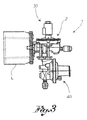
- a shut-off unit comprising a remotely-controlled trigger device and a pressure-switch trigger device
- the shaft is disengaged and shuts off the transit of fluid both when the entity of the oscillations is detected by an accelerometer connected to the actuator, and when an excessive reduction or excessive increase in the pressure of the fluid occurs, for example as a result of damage to the distribution line.
- the shut-off unit according to the present invention is extremely reliable, in that the shutting-off of the line follows the occurrence of causes independent of each other.
Landscapes
- Engineering & Computer Science (AREA)
- General Engineering & Computer Science (AREA)
- Mechanical Engineering (AREA)
- Feeding And Controlling Fuel (AREA)
- Gas Separation By Absorption (AREA)
- Regulation And Control Of Combustion (AREA)
- Control Of Combustion (AREA)
- Catching Or Destruction (AREA)
- Filling Or Discharging Of Gas Storage Vessels (AREA)
Abstract
Description
- The present invention relates to a shut-off unit with double trigger, that is a shut-off unit able to intervene to prevent the transit of a fluid in a distribution line following occurrence of a terrestrial movement, on the basis of independent triggering circumstances.
- In the sector of safety devices for seismic risk, inertially-activated shut-off devices which are subsequently reset manually are known of, which shut off the distribution line they are mounted on when a terrestrial movement exceeds the intensity of a predefined, minimum threshold. One solution known of, for example is that referred to in the Italian patent application for invention
BS2006A000099 BS2006A000103 - Remotely-controlled, shut-off devices with manual reset are also known of, in other words such as to be remotely activated by a sensor connected to an accelerometer. One solution is known of from the Italian patent application for the Utility Model
MI2006U000217 - Pressure switch operated shut-off devices are also known of, such as to cut in when the value of the pressure in the line is below a minimum threshold (or above a maximum threshold). An example is shown in the Italian invention patent
IT 1303464 DE-A-199 52 610 ) in the Applicant's name. - However an increasing need is felt to ensure the intervention of a shut-off device in the event of a telluric event occurring, whilst preventing false alarms. Such false alarms are often due to the device being overly sensitive and interrupting the transit of fluid even when a telluric situation has not arisen.
- The purpose of the present invention is to produce a shut-off group for a fluid, especially for anti-seismic use, with particularly well-developed safety and reliability characteristics, in that the actuation of such occurs on the basis of the occurrence of various and different external circumstances.
- Such purpose is achieved by a shut-off unit produced according to
claim 1 below. The claims dependent on this describe embodiment variations. - The characteristics and advantages of the shut-off unit according to the present invention will be evident from the description given below, by way of example and not limited to such, according to the attached figures, wherein:
- -
figure 1 shows a shut-off unit comprising an inertial trigger device and a remote control trigger device; - -
figure 2 shows a shut-off unit comprising an inertial trigger device and a pressure-switch trigger device; - -
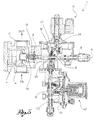
figure 3 shows a shut-off unit comprising a remote-control trigger device and a pressure-switch trigger device; - -
figure 4 shows a cross-section of the shut-off unit offigure 1 , comprising an inertial trigger device and a remote-control trigger device; and - -
figure 5 shows a cross-section of the shut-off unit offigure 3 , comprising a remote-control trigger device and a pressure-switch trigger device. - With reference to the attached figures,
reference numeral 1 globally denotes a shut-off unit according to the present invention. -
Unit 1 comprises an obturator device able to move from an open configuration in which the transit of fluid from the input pipe to the output pipe is allowed, to a closed configuration in which said transit is impeded. - The obturator device comprises a main body 2a, able to be joined to the input pipe 4 and the
output pipe 6 of a distribution line L of a fluid, for example of gas. - The obturator device also comprises a shaft 8 extending mainly along a shaft axis X, supported in a translatable manner inside the main body. Specifically, the shaft can be translated from a closed position, in which the obturator device is in the closed configuration, to an open position, in which the obturator device is in the open configuration.
- The obturator device comprises, in addition, an
obturator 10, for example discoid and fitted with seals, positioned at the head of the shaft, so as to close off the fluidic communication between the input pipe and the output pipe when the device is in the closed configuration. - Furthermore, the obturator device comprises activators able to act on the shaft 8 so as to move it from the open position to the closed position; for example, the activators comprise an
elastic element 14, placed in compression between the shaft 8 and the main body 2a to push the shaft from the open position to the closed position. - In addition, the obturator device comprises means of retention able to keep the shaft 8 in the open position, in contrast with said activators.
- Preferably, the means of retention comprise a supporting
body 16, moving in translation, and a lever 18, hinged to the supportingbody 16, suitable for rotation from an engaged position, in which it is engaged with the shaft 8 so as to retain it, to a release position, in which it does not retain the shaft 8. - The means of retention comprise, moreover, a
pin 20, mobile in translation in the lever 18, directly engaged on the shaft 8 in the engaged position of the lever, and aspring 22, compressed between thepin 20 and the lever 18, able to constantly influence the lever to move it from the engaged position to the release position. - In addition, the means of retention comprise a
cam element 24, able to pass from an engaged position, in which it influences the lever keeping it in its engaged position, to a release position, in which it does not retain the lever, thus free to pass to the release position. - The shut-off unit also comprises a
first trigger device 30, able to act on said obturator device, to move it from the open configuration to the closed configuration. The first trigger device is chosen from the group comprising inertial, remote-control, and pressure switch devices. - In addition, the shut-off unit comprises a
second trigger device 40, able to act on said obturator device, to move it from the open configuration to the closed configuration. The second trigger device, different from the first, is also chosen from the group comprising inertial, remote-control, and pressure switch devices. - The first and second trigger devices are both mounted on the main body 2a of the obturator device and, specifically, are able to co-operate with the shaft 8 to enable the obturator device to pass from the open to the closed configuration.
- Specifically, the
first trigger device 30 can engage with the lever 18 of the means of retention and thesecond trigger device 40 can engage with the supportingbody 16, to disactivate the means of retention. - In addition, the
first trigger device 30 is joined to thecam element 24. - According to a preferred form of embodiment, the inertial trigger device comprises a rocker arm 50 able to oscillate and a
first trigger shaft 52, able to be t influenced by the oscillating rocker arm and engaged with the obturator device to keep it in the open configuration, as well as to disengage from it by means of the rocker arm. - For example the
first trigger shaft 52 is joined to thecam element 24, positioned at the head of it. - According to a further example, the first trigger shaft can engage with the supporting
body 16 of the means of retention so as to disactivate it. - According to a further form of embodiment, the remotely-controlled trigger device comprises an
actuator 60 which moves on receipt of an electric or radio signal and a second trigger shaft 62, which may be influenced by the actuator, engaged with the obturator device to keep it in the open position. - For example, the second trigger shaft 62 may be engaged with the means of retention, for example, to the supporting
body 16 of it, so as to disactivate it and allow the movement of the shaft 8 to the closed position. - According to a further example (not shown), the second trigger shaft 62 is joined to the
cam element 24. - According to yet a further form of embodiment (
figure 5 ), the pressure-switch trigger device comprises aflexible membrane 70 which defines apressure chamber 72 inside the body of the device in fluidic communication with the distribution line L so as to be sensitive to the pressure of the fluid, and athird trigger shaft 74, engaged with the obturator device to keep it in the open configuration. For example thethird trigger shaft 74 can engage with the means of retention, for example with the supportingbody 16 of it, to disactivate it. - According to a further example of embodiment (not shown), the
third trigger shaft 74 is joined to thecam element 24 situated at the head of the same. - During normal functioning of a shut-off unit comprising an inertial trigger device and a remotely-controlled trigger device, the shaft is disengaged from the means of retention and shuts off the transit of fluid both when the entity of the oscillations is such as to activate the inertial device, and when such tremors are detected by an accelerometer, connected to the actuator.
- During normal functioning of a shut-off unit comprising an inertial trigger device and a pressure switch trigger device, the shaft is disengaged and shuts off the transit of fluid both when the entity of the oscillations is such as to activate the inertial device, and when an excessive reduction or excessive increase in the pressure of the fluid occurs, for example as a result of damage to the distribution line.
- During normal functioning of a shut-off unit comprising a remotely-controlled trigger device and a pressure-switch trigger device, the shaft is disengaged and shuts off the transit of fluid both when the entity of the oscillations is detected by an accelerometer connected to the actuator, and when an excessive reduction or excessive increase in the pressure of the fluid occurs, for example as a result of damage to the distribution line.
- lnnovatively, the shut-off unit according to the present invention is extremely reliable, in that the shutting-off of the line follows the occurrence of causes independent of each other.
- It is clear that a technician skilled in this sector may make modifications to the functional unit described above so as to satisfy contingent and specific requirements, all moreover contained within the scope of protection as defined by the following claims.
Claims (10)
- Shut-off unit (1) which can be joined to an input pipe (4) and an output pipe (6) of a distribution line of a fluid, comprising:an obturator device (2) able to pass from an open configuration, in which the transit of fluid from the input pipe to the output pipe is allowed, to a closed configuration, in which said transit is impeded: comprising activators able to act said closed configuration and means of retention able to retain said open configuration;- a first trigger device (30) able to act on said obturator device to change it from the open configuration to the closed configuration, said first trigger device being chosen from a group comprising inertial-activated, remotely-controlled by a sensor connected to an accelerometer, and pressure-switch operated devices;- a second trigger device (40) able to act on said obturator device to change it from the open configuration to the closed configuration, said second trigger device, different from the first device, being chosen from the group comprising inertial-activated, remotely-controlled by a sensor connected to an accelerometer, and pressure-switchoperated devices;
wherein said means of retention comprise- a supporting body (16);- a lever (18); andwherein the first trigger device can engage with the lever (18) and the second trigger device can engage with the supporting body (16), to deactivate the means of retention. - Unit according to claim 1, wherein the obturator device comprises a main body (2a), said first and second trigger devices being mounted on said body.
- Unit according to claim 2, wherein- the obturator device comprises a shaft (8) able to translate from a closed position, in which the obturator device is in the closed configuration, to an open position, wherein the obturator device is in the open configuration; and- the first and second trigger devices are able to co-operate with said shaft so as to allow the passage from the open to the closed configuration.
- Unit according to claim 3, comprising- said activators able to act on the shaft to move it from the open position to the closed position;- said means of retention which are able to keep the shaft in the open position, in contrast with said activators;wherein the first and second trigger devices are able to co-operate with said means of retention.
- Unit according to claim 4, wherein the activators comprise an elastic element (14).
- Unit according to claims 4 or 5, wherein the means of retention comprise- the supporting body (16), mobile in translation;- the lever (18), hinged to the supporting body, able to be rotated from an engaged position, in which it is engaged with the shaft so as to retain it, to a release position, in which it does not retain the shaft.
- Unit according to claim 6, wherein the means cf retention comprise, in addition:- a pin (20), mobile in translation in the lever, directly engaged to the shaft in the engaged position of the lever;- a spring (22), compressed between the pin and the lever, able to constantly influence the lever so as to move it from the engaged to the release position;- a cam element (24), able to move from an engaged position, in which it influences the lever by holding it in the engaged position, to a release position, in which it does not hold the lever, thus free to move to the release position;wherein the first trigger device is joined to the cam element.
- Unit according to any of the previous claims, wherein the inertial trigger device comprises:- a rocker arm (50) able to oscillate;- a first trigger shaft (52), able to be influenced by the oscillating rocker arm, engaged with the obturator device to keep it in the open configuration and which may be disengaged from it by the action of the rocker arm.
- Unit according to any of the previous claims, wherein the remotely-controlled trigger device comprises:- an actuator (60) moving on receipt of an electric or radio signal;- a second trigger shaft (62), which can be influenced by the actuator, engaged with the obturator device so as to keep it in the open configuration.
- Unit according to any of the previous claims, wherein the pressure-switch trigger device comprises- a flexible membrane (70) defining a pressure chamber (72) inside the body, in fluidic communication with the input and output pipes;- a third trigger shaft (74), joined to the membrane, engaged with the obturator device to keep it in the open configuration.
Applications Claiming Priority (1)
| Application Number | Priority Date | Filing Date | Title |
|---|---|---|---|
| IT000172A ITBS20070172A1 (en) | 2007-11-08 | 2007-11-08 | INTERCEPTING GROUP OF A FLUID, FOR EXAMPLE GAS, WITH DUPLICATE INNESCO |
Related Parent Applications (1)
| Application Number | Title | Priority Date | Filing Date |
|---|---|---|---|
| ITBS20070172 Previously-Filed-Application | 2007-11-08 |
Publications (3)
| Publication Number | Publication Date |
|---|---|
| EP2058569A2 EP2058569A2 (en) | 2009-05-13 |
| EP2058569A3 EP2058569A3 (en) | 2010-01-20 |
| EP2058569B1 true EP2058569B1 (en) | 2011-10-19 |
Family
ID=40314555
Family Applications (1)
| Application Number | Title | Priority Date | Filing Date |
|---|---|---|---|
| EP07425839A Active EP2058569B1 (en) | 2007-11-08 | 2007-12-31 | Shut-off unit for a fluid, such as gas, with double trigger |
Country Status (4)
| Country | Link |
|---|---|
| EP (1) | EP2058569B1 (en) |
| AT (1) | ATE529678T1 (en) |
| ES (1) | ES2373924T3 (en) |
| IT (1) | ITBS20070172A1 (en) |
Cited By (1)
| Publication number | Priority date | Publication date | Assignee | Title |
|---|---|---|---|---|
| DE102011005260B3 (en) * | 2011-03-08 | 2012-06-14 | Tyczka Totalgaz Gmbh | Safety shut-off valve and method for shutting off a gas line |
Families Citing this family (1)
| Publication number | Priority date | Publication date | Assignee | Title |
|---|---|---|---|---|
| ITUB20152323A1 (en) * | 2015-07-20 | 2017-01-20 | Pietro Fiorentini Spa | BLOCK VALVE FOR GAS AND METHOD OF CONSTRUCTION OF SUCH BLOCKING VALVE |
Family Cites Families (2)
| Publication number | Priority date | Publication date | Assignee | Title |
|---|---|---|---|---|
| US5960807A (en) * | 1998-05-05 | 1999-10-05 | Reyman; Mark | Vibration and flow actuated valve shutoff system |
| IT1303464B1 (en) | 1998-11-24 | 2000-11-06 | Fiorentini Minireg S P A | LOW AND HIGH PRESSURE BLOCK VALVE |
-
2007
- 2007-11-08 IT IT000172A patent/ITBS20070172A1/en unknown
- 2007-12-31 AT AT07425839T patent/ATE529678T1/en not_active IP Right Cessation
- 2007-12-31 ES ES07425839T patent/ES2373924T3/en active Active
- 2007-12-31 EP EP07425839A patent/EP2058569B1/en active Active
Cited By (1)
| Publication number | Priority date | Publication date | Assignee | Title |
|---|---|---|---|---|
| DE102011005260B3 (en) * | 2011-03-08 | 2012-06-14 | Tyczka Totalgaz Gmbh | Safety shut-off valve and method for shutting off a gas line |
Also Published As
| Publication number | Publication date |
|---|---|
| ATE529678T1 (en) | 2011-11-15 |
| EP2058569A2 (en) | 2009-05-13 |
| ITBS20070172A1 (en) | 2009-05-09 |
| ES2373924T3 (en) | 2012-02-10 |
| EP2058569A3 (en) | 2010-01-20 |
Similar Documents
| Publication | Publication Date | Title |
|---|---|---|
| WO2008131153A3 (en) | Slam shut safety device | |
| EP0275155B1 (en) | Fluid leak detector | |
| MY167547A (en) | A safety mechanism for a well, a well comprising the safety mechanism, and related methods | |
| RU2012144285A (en) | UNDERGROUND WELL VALVE, ACTIVATED BY DIFFERENTIAL PRESSURE | |
| WO2010009488A3 (en) | Method for operating a mobile hand-operated device for the giving or triggering of potentially dangerous control commands and corresponding hand-operated device | |
| WO2007019038A3 (en) | Wound irrigation device pressure monitoring and control system | |
| DE502005003985D1 (en) | PNEUMATIC PRESSURE CONTROL VALVE | |
| CN205371730U (en) | By automatic valve of depression bar unstability trigger action during superpressure | |
| KR20120091574A (en) | Door-closer for prevention of fire | |
| EP2058569A2 (en) | Shut-off unit for a fluid, such as gas, with double trigger | |
| US6789566B1 (en) | Safety contrivance for gas-using device | |
| CN214171436U (en) | Cut-off valve | |
| WO2021056613A1 (en) | Device capable of quickly and automatically closing and emergency shutoff device at natural gas wellhead | |
| US3892258A (en) | High pressure safety valve | |
| CN108825833A (en) | A kind of valve system with isolating device | |
| WO2008116595A3 (en) | Hand-held robot-programming device | |
| RU16024U1 (en) | EMERGENCY CLOSING AUTOMATIC GAS PIPELINE | |
| KR200472437Y1 (en) | Alarm valve | |
| JP2007327584A (en) | Flowing water detector | |
| GB2363330A (en) | Air pressure stabilising device | |
| ATE494256T1 (en) | RADIO REMOTE CONTROL DEVICE FOR A WORKING DEVICE | |
| JP4796898B2 (en) | Flowing water detector | |
| US3262323A (en) | Control device | |
| CN107940071A (en) | It is emergent to automatically control Electric Actuator | |
| CA2078055A1 (en) | A safety and automatic stop device, in particular for gas expansion stations |
Legal Events
| Date | Code | Title | Description |
|---|---|---|---|
| PUAI | Public reference made under article 153(3) epc to a published international application that has entered the european phase |
Free format text: ORIGINAL CODE: 0009012 |
|
| AK | Designated contracting states |
Kind code of ref document: A2 Designated state(s): AT BE BG CH CY CZ DE DK EE ES FI FR GB GR HU IE IS IT LI LT LU LV MC MT NL PL PT RO SE SI SK TR |
|
| AX | Request for extension of the european patent |
Extension state: AL BA HR MK RS |
|
| PUAL | Search report despatched |
Free format text: ORIGINAL CODE: 0009013 |
|
| AK | Designated contracting states |
Kind code of ref document: A3 Designated state(s): AT BE BG CH CY CZ DE DK EE ES FI FR GB GR HU IE IS IT LI LT LU LV MC MT NL PL PT RO SE SI SK TR |
|
| AX | Request for extension of the european patent |
Extension state: AL BA HR MK RS |
|
| 17P | Request for examination filed |
Effective date: 20100218 |
|
| 17Q | First examination report despatched |
Effective date: 20100317 |
|
| RAP1 | Party data changed (applicant data changed or rights of an application transferred) |
Owner name: PIETRO FIORENTINI S.P.A. |
|
| AKX | Designation fees paid |
Designated state(s): AT BE BG CH CY CZ DE DK EE ES FI FR GB GR HU IE IS IT LI LT LU LV MC MT NL PL PT RO SE SI SK TR |
|
| GRAP | Despatch of communication of intention to grant a patent |
Free format text: ORIGINAL CODE: EPIDOSNIGR1 |
|
| GRAS | Grant fee paid |
Free format text: ORIGINAL CODE: EPIDOSNIGR3 |
|
| GRAA | (expected) grant |
Free format text: ORIGINAL CODE: 0009210 |
|
| AK | Designated contracting states |
Kind code of ref document: B1 Designated state(s): AT BE BG CH CY CZ DE DK EE ES FI FR GB GR HU IE IS IT LI LT LU LV MC MT NL PL PT RO SE SI SK TR |
|
| REG | Reference to a national code |
Ref country code: GB Ref legal event code: FG4D |
|
| REG | Reference to a national code |
Ref country code: CH Ref legal event code: EP |
|
| REG | Reference to a national code |
Ref country code: IE Ref legal event code: FG4D |
|
| REG | Reference to a national code |
Ref country code: DE Ref legal event code: R096 Ref document number: 602007018020 Country of ref document: DE Effective date: 20120112 |
|
| REG | Reference to a national code |
Ref country code: NL Ref legal event code: VDEP Effective date: 20111019 |
|
| REG | Reference to a national code |
Ref country code: ES Ref legal event code: FG2A Ref document number: 2373924 Country of ref document: ES Kind code of ref document: T3 Effective date: 20120210 |
|
| LTIE | Lt: invalidation of european patent or patent extension |
Effective date: 20111019 |
|
| REG | Reference to a national code |
Ref country code: AT Ref legal event code: MK05 Ref document number: 529678 Country of ref document: AT Kind code of ref document: T Effective date: 20111019 |
|
| PG25 | Lapsed in a contracting state [announced via postgrant information from national office to epo] |
Ref country code: LT Free format text: LAPSE BECAUSE OF FAILURE TO SUBMIT A TRANSLATION OF THE DESCRIPTION OR TO PAY THE FEE WITHIN THE PRESCRIBED TIME-LIMIT Effective date: 20111019 Ref country code: IS Free format text: LAPSE BECAUSE OF FAILURE TO SUBMIT A TRANSLATION OF THE DESCRIPTION OR TO PAY THE FEE WITHIN THE PRESCRIBED TIME-LIMIT Effective date: 20120219 Ref country code: BE Free format text: LAPSE BECAUSE OF FAILURE TO SUBMIT A TRANSLATION OF THE DESCRIPTION OR TO PAY THE FEE WITHIN THE PRESCRIBED TIME-LIMIT Effective date: 20111019 |
|
| PG25 | Lapsed in a contracting state [announced via postgrant information from national office to epo] |
Ref country code: NL Free format text: LAPSE BECAUSE OF FAILURE TO SUBMIT A TRANSLATION OF THE DESCRIPTION OR TO PAY THE FEE WITHIN THE PRESCRIBED TIME-LIMIT Effective date: 20111019 Ref country code: PT Free format text: LAPSE BECAUSE OF FAILURE TO SUBMIT A TRANSLATION OF THE DESCRIPTION OR TO PAY THE FEE WITHIN THE PRESCRIBED TIME-LIMIT Effective date: 20120220 Ref country code: GR Free format text: LAPSE BECAUSE OF FAILURE TO SUBMIT A TRANSLATION OF THE DESCRIPTION OR TO PAY THE FEE WITHIN THE PRESCRIBED TIME-LIMIT Effective date: 20120120 Ref country code: SE Free format text: LAPSE BECAUSE OF FAILURE TO SUBMIT A TRANSLATION OF THE DESCRIPTION OR TO PAY THE FEE WITHIN THE PRESCRIBED TIME-LIMIT Effective date: 20111019 Ref country code: LV Free format text: LAPSE BECAUSE OF FAILURE TO SUBMIT A TRANSLATION OF THE DESCRIPTION OR TO PAY THE FEE WITHIN THE PRESCRIBED TIME-LIMIT Effective date: 20111019 Ref country code: SI Free format text: LAPSE BECAUSE OF FAILURE TO SUBMIT A TRANSLATION OF THE DESCRIPTION OR TO PAY THE FEE WITHIN THE PRESCRIBED TIME-LIMIT Effective date: 20111019 |
|
| PG25 | Lapsed in a contracting state [announced via postgrant information from national office to epo] |
Ref country code: CY Free format text: LAPSE BECAUSE OF FAILURE TO SUBMIT A TRANSLATION OF THE DESCRIPTION OR TO PAY THE FEE WITHIN THE PRESCRIBED TIME-LIMIT Effective date: 20111019 |
|
| PG25 | Lapsed in a contracting state [announced via postgrant information from national office to epo] |
Ref country code: BG Free format text: LAPSE BECAUSE OF FAILURE TO SUBMIT A TRANSLATION OF THE DESCRIPTION OR TO PAY THE FEE WITHIN THE PRESCRIBED TIME-LIMIT Effective date: 20120119 Ref country code: EE Free format text: LAPSE BECAUSE OF FAILURE TO SUBMIT A TRANSLATION OF THE DESCRIPTION OR TO PAY THE FEE WITHIN THE PRESCRIBED TIME-LIMIT Effective date: 20111019 Ref country code: MC Free format text: LAPSE BECAUSE OF NON-PAYMENT OF DUE FEES Effective date: 20111231 Ref country code: SK Free format text: LAPSE BECAUSE OF FAILURE TO SUBMIT A TRANSLATION OF THE DESCRIPTION OR TO PAY THE FEE WITHIN THE PRESCRIBED TIME-LIMIT Effective date: 20111019 Ref country code: CZ Free format text: LAPSE BECAUSE OF FAILURE TO SUBMIT A TRANSLATION OF THE DESCRIPTION OR TO PAY THE FEE WITHIN THE PRESCRIBED TIME-LIMIT Effective date: 20111019 Ref country code: DK Free format text: LAPSE BECAUSE OF FAILURE TO SUBMIT A TRANSLATION OF THE DESCRIPTION OR TO PAY THE FEE WITHIN THE PRESCRIBED TIME-LIMIT Effective date: 20111019 |
|
| REG | Reference to a national code |
Ref country code: CH Ref legal event code: PL |
|
| PLBE | No opposition filed within time limit |
Free format text: ORIGINAL CODE: 0009261 |
|
| STAA | Information on the status of an ep patent application or granted ep patent |
Free format text: STATUS: NO OPPOSITION FILED WITHIN TIME LIMIT |
|
| PG25 | Lapsed in a contracting state [announced via postgrant information from national office to epo] |
Ref country code: RO Free format text: LAPSE BECAUSE OF FAILURE TO SUBMIT A TRANSLATION OF THE DESCRIPTION OR TO PAY THE FEE WITHIN THE PRESCRIBED TIME-LIMIT Effective date: 20111019 Ref country code: IT Free format text: LAPSE BECAUSE OF FAILURE TO SUBMIT A TRANSLATION OF THE DESCRIPTION OR TO PAY THE FEE WITHIN THE PRESCRIBED TIME-LIMIT Effective date: 20111019 Ref country code: PL Free format text: LAPSE BECAUSE OF FAILURE TO SUBMIT A TRANSLATION OF THE DESCRIPTION OR TO PAY THE FEE WITHIN THE PRESCRIBED TIME-LIMIT Effective date: 20111019 |
|
| REG | Reference to a national code |
Ref country code: FR Ref legal event code: ST Effective date: 20120831 |
|
| 26N | No opposition filed |
Effective date: 20120720 |
|
| GBPC | Gb: european patent ceased through non-payment of renewal fee |
Effective date: 20120119 |
|
| REG | Reference to a national code |
Ref country code: IE Ref legal event code: MM4A |
|
| REG | Reference to a national code |
Ref country code: DE Ref legal event code: R119 Ref document number: 602007018020 Country of ref document: DE Effective date: 20120703 |
|
| PG25 | Lapsed in a contracting state [announced via postgrant information from national office to epo] |
Ref country code: CH Free format text: LAPSE BECAUSE OF NON-PAYMENT OF DUE FEES Effective date: 20111231 Ref country code: DE Free format text: LAPSE BECAUSE OF NON-PAYMENT OF DUE FEES Effective date: 20120703 Ref country code: GB Free format text: LAPSE BECAUSE OF NON-PAYMENT OF DUE FEES Effective date: 20120119 Ref country code: LI Free format text: LAPSE BECAUSE OF NON-PAYMENT OF DUE FEES Effective date: 20111231 Ref country code: IE Free format text: LAPSE BECAUSE OF NON-PAYMENT OF DUE FEES Effective date: 20111231 |
|
| PG25 | Lapsed in a contracting state [announced via postgrant information from national office to epo] |
Ref country code: AT Free format text: LAPSE BECAUSE OF FAILURE TO SUBMIT A TRANSLATION OF THE DESCRIPTION OR TO PAY THE FEE WITHIN THE PRESCRIBED TIME-LIMIT Effective date: 20111019 |
|
| PG25 | Lapsed in a contracting state [announced via postgrant information from national office to epo] |
Ref country code: MT Free format text: LAPSE BECAUSE OF FAILURE TO SUBMIT A TRANSLATION OF THE DESCRIPTION OR TO PAY THE FEE WITHIN THE PRESCRIBED TIME-LIMIT Effective date: 20111019 |
|
| PG25 | Lapsed in a contracting state [announced via postgrant information from national office to epo] |
Ref country code: FR Free format text: LAPSE BECAUSE OF NON-PAYMENT OF DUE FEES Effective date: 20120102 |
|
| PG25 | Lapsed in a contracting state [announced via postgrant information from national office to epo] |
Ref country code: LU Free format text: LAPSE BECAUSE OF NON-PAYMENT OF DUE FEES Effective date: 20111231 |
|
| PG25 | Lapsed in a contracting state [announced via postgrant information from national office to epo] |
Ref country code: FI Free format text: LAPSE BECAUSE OF FAILURE TO SUBMIT A TRANSLATION OF THE DESCRIPTION OR TO PAY THE FEE WITHIN THE PRESCRIBED TIME-LIMIT Effective date: 20111019 |
|
| PG25 | Lapsed in a contracting state [announced via postgrant information from national office to epo] |
Ref country code: HU Free format text: LAPSE BECAUSE OF FAILURE TO SUBMIT A TRANSLATION OF THE DESCRIPTION OR TO PAY THE FEE WITHIN THE PRESCRIBED TIME-LIMIT Effective date: 20111019 |
|
| PGFP | Annual fee paid to national office [announced via postgrant information from national office to epo] |
Ref country code: TR Payment date: 20221226 Year of fee payment: 16 Ref country code: ES Payment date: 20230224 Year of fee payment: 16 |
|
| REG | Reference to a national code |
Ref country code: ES Ref legal event code: FD2A Effective date: 20250204 |
|
| PG25 | Lapsed in a contracting state [announced via postgrant information from national office to epo] |
Ref country code: ES Free format text: LAPSE BECAUSE OF NON-PAYMENT OF DUE FEES Effective date: 20240101 |