EP2058530A2 - Intelligent fastener installation system - Google Patents
Intelligent fastener installation system Download PDFInfo
- Publication number
- EP2058530A2 EP2058530A2 EP08253538A EP08253538A EP2058530A2 EP 2058530 A2 EP2058530 A2 EP 2058530A2 EP 08253538 A EP08253538 A EP 08253538A EP 08253538 A EP08253538 A EP 08253538A EP 2058530 A2 EP2058530 A2 EP 2058530A2
- Authority
- EP
- European Patent Office
- Prior art keywords
- information
- fastener
- collar
- code
- computer
- Prior art date
- Legal status (The legal status is an assumption and is not a legal conclusion. Google has not performed a legal analysis and makes no representation as to the accuracy of the status listed.)
- Granted
Links
Images





Classifications
-
- B—PERFORMING OPERATIONS; TRANSPORTING
- B21—MECHANICAL METAL-WORKING WITHOUT ESSENTIALLY REMOVING MATERIAL; PUNCHING METAL
- B21J—FORGING; HAMMERING; PRESSING METAL; RIVETING; FORGE FURNACES
- B21J15/00—Riveting
- B21J15/10—Riveting machines
- B21J15/28—Control devices specially adapted to riveting machines not restricted to one of the preceding subgroups
-
- B—PERFORMING OPERATIONS; TRANSPORTING
- B21—MECHANICAL METAL-WORKING WITHOUT ESSENTIALLY REMOVING MATERIAL; PUNCHING METAL
- B21J—FORGING; HAMMERING; PRESSING METAL; RIVETING; FORGE FURNACES
- B21J15/00—Riveting
- B21J15/02—Riveting procedures
- B21J15/022—Setting rivets by means of swaged-on locking collars, e.g. lockbolts
-
- B—PERFORMING OPERATIONS; TRANSPORTING
- B25—HAND TOOLS; PORTABLE POWER-DRIVEN TOOLS; MANIPULATORS
- B25B—TOOLS OR BENCH DEVICES NOT OTHERWISE PROVIDED FOR, FOR FASTENING, CONNECTING, DISENGAGING, OR HOLDING
- B25B13/00—Spanners; Wrenches
- B25B13/56—Spanner sets
-
- B—PERFORMING OPERATIONS; TRANSPORTING
- B25—HAND TOOLS; PORTABLE POWER-DRIVEN TOOLS; MANIPULATORS
- B25B—TOOLS OR BENCH DEVICES NOT OTHERWISE PROVIDED FOR, FOR FASTENING, CONNECTING, DISENGAGING, OR HOLDING
- B25B27/00—Hand tools, specially adapted for fitting together or separating parts or objects whether or not involving some deformation, not otherwise provided for
- B25B27/0007—Tools for fixing internally screw-threaded tubular fasteners
- B25B27/0014—Tools for fixing internally screw-threaded tubular fasteners motor-driven
-
- F—MECHANICAL ENGINEERING; LIGHTING; HEATING; WEAPONS; BLASTING
- F16—ENGINEERING ELEMENTS AND UNITS; GENERAL MEASURES FOR PRODUCING AND MAINTAINING EFFECTIVE FUNCTIONING OF MACHINES OR INSTALLATIONS; THERMAL INSULATION IN GENERAL
- F16B—DEVICES FOR FASTENING OR SECURING CONSTRUCTIONAL ELEMENTS OR MACHINE PARTS TOGETHER, e.g. NAILS, BOLTS, CIRCLIPS, CLAMPS, CLIPS OR WEDGES; JOINTS OR JOINTING
- F16B2200/00—Constructional details of connections not covered for in other groups of this subclass
- F16B2200/95—Constructional details of connections not covered for in other groups of this subclass with markings, colours, indicators or the like
-
- G—PHYSICS
- G05—CONTROLLING; REGULATING
- G05B—CONTROL OR REGULATING SYSTEMS IN GENERAL; FUNCTIONAL ELEMENTS OF SUCH SYSTEMS; MONITORING OR TESTING ARRANGEMENTS FOR SUCH SYSTEMS OR ELEMENTS
- G05B2219/00—Program-control systems
- G05B2219/30—Nc systems
- G05B2219/49—Nc machine tool, till multiple
- G05B2219/49302—Part, workpiece, code, tool identification
Definitions
- a fastening apparatus, and/or method of installing, locating, tracking, and/or monitoring a fastener is needed to decrease one or more problems associated with one or more of the existing fastening apparatus and/or methods.
- a method of installing a fastener comprises: (1) providing at least one of a fastener and a collar having a code; (2) scanning the code and retrieving first information regarding the at least one fastener and collar; (3) communicating the first information to a computer, the computer accessible to at least one database; (4) storing the first information in the at least one database; (5) communicating second information using the computer to a tool based on the first information; and (6) fastening the at least one fastener and collar using the second information and the tool.
- a method of tracking and monitoring a fastener in an apparatus In one step, at least one of a fastener and a collar is provided attached at a location of the apparatus. The at least one fastener and collar has a code. In another step, the code is scanned and at least one of first information, second information, third information, and fourth information regarding the at least one fastener and collar is retrieved using a computer.
- a method of locating a fastener in an apparatus comprises: (1) providing at least one of a fastener and a collar having a code attached at a location of the apparatus; (2) providing a computer having cross-linked to the code at least one of first information, second information, third information, and fourth information regarding the at least one fastener and collar; and (3) determining a location of the at least one of fastener and collar using the computer.
- a fastening apparatus in still another aspect of the disclosure, includes at least one of a fastener and a collar having a code.
- the code is cross-linked in at least one database of a computer to at least one of first information, second information, third information, and fourth information regarding the at least one fastener and collar.
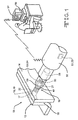
- FIG. 1 shows a perspective view, with dashed lines showing hidden elements, of one embodiment of a fastening apparatus 10 being attached to two components 12 and 14 of an apparatus 16.
- the fastening apparatus 10 may comprise at least one of a fastener 18 and collar 21.
- the fastener 18 may comprise a one-piece fastener which may be attached without the use of collar 21, or may comprise a two-piece fastener which may be attached using collar 21.
- the fastener 18 may comprise an externally threaded bolt 19 which is inserted at a location 17 of the apparatus 16 through a hole 22 extending through the two components 12 and 14.
- the collar 21 may comprise an internally threaded nut 40 which screws onto the fastener 18 to lock the components 12 and 14 of the apparatus 10 together.
- the apparatus 16, including its components 12 and 14, may comprise a portion of an aircraft. In other embodiments, the apparatus 16 may comprise varying non-aircraft applications.
- Figure 2 shows a side-view of the fastener 18 of the embodiment of Figure 1 .
- Figure 2A shows a top view of the fastener 18 of the embodiment of Figure 1 .
- the fastener 18 may comprise a bolt 19 having a head 22, external threads 24, and an end surface 26.
- One or more portions 28 of the end surface 26 may be marked with a code 30.
- the code 30 may comprise laser reader markings 32 or other types of markings.
- Figure 2B shows a block diagram showing the types of information the code 30 of the fastener 18 may provide.
- the code 30 may provide first information 32 regarding the fastener 18 such as supplier identification 33, part number 34, lot number 35, batch number 36, material 37, type 38 (which may include size), date 39, and other types of information regarding the fastener 18.
- the fastener 18 may be in varying shapes, sizes, orientations, and configurations, and the code 30 may be on or in a varying portion of the fastener 18.
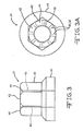
- Figure 3 shows a side-view of the collar 21 of the embodiment of Figure 1 , with the dashed lines depicting hidden elements.
- Figure 3A shows a top view of the collar 21 of the embodiment of Figure 1 .
- the collar 21 may comprise a nut 40 having a flange 41, internal threads 42, and an end surface 43.
- One or more portions 44 of the end surface 43 may be marked with a code 30.
- the code 30 may comprise laser reading markings 32 or other types of markings.
- the code 30 may provide the various types of first information 32 shown in Figure 2B regarding the collar 21.
- the code 30 may provide first information 32 regarding the collar 21 such as supplier identification 33, part number 34, lot number 35, batch number 36, material 37, type 38 (which may include size), date 39, and other types of information regarding the collar 21.
- the collar 21 may be in varying shapes, sizes, orientations, and configurations, and the code 30 may be on or in a varying portion of the collar 21.
- Figure 4 shows a side-view, with dashed lines depicting hidden elements, of another embodiment of a collar 21 comprising a sleeve 45 which may be attached to the fastener 18 of Figure 1 instead of the nut 40.
- Figure 4A shows a top view of the sleeve 45 of the embodiment of Figure 4 .
- the sleeve 45 may comprise a flange 46, internal threads 47 (which are shown in hidden lines), and an end surface 48.
- One or more portions 49 of the end surface 48 may be marked with a code 30.
- the code 30 may comprise laser reading markings 32 or other types of markings.
- the code 30 may provide the various types of first information 32 shown in Figure 2B regarding the sleeve 45.
- the code 30 may provide first information 32 regarding the sleeve 45 such as supplier identification 33, part number 34, lot number 35, batch number 36, material 37, type 38 (which may include size), date 39, and other types of information regarding the sleeve 45.
- the collar 21 may be in varying shapes, sizes, orientations, and configurations, and the code 30 may be on or in a varying portion of the collar 21.
- the collar 21 may be screwed onto the fastener 18 using a tool 50 such as a ratchet or other type of tool 50 which is adapted to screw the collar 21 onto the fastener 18 to lock the components 12 and 14 together.
- the fastener 18 may be fastened without the use of collar 21.
- the tool 50 may have a smart chip 51 embedded within an outer surface 52 of the tool 50.
- An inner surface 53 defining a hole 54 may extend linearly from an end 59 of the tool 50.
- the inner surface 53 may be adapted to latch onto the collar 21 to screw the collar 21 onto the fastener 18.
- a laser reader 55 such as an optical laser reader, may be disposed within the hole 54.
- the laser reader 55 may be adapted to scan and read the code 30 of the fastener 18 and/or the collar 21 in order to retrieve the first information 32 regarding the fastener 18 and/or the collar 21.
- the first information 32 may be stored in the smart chip 51.
- the smart chip 51 may be in wireless contact with a computer 56 which has access and is in communication with one or more databases 57.
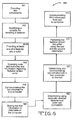
- FIG. 5 shows a flowchart of one embodiment of a method 160 of installing a fastener 18.
- two components 12 and 14 may be provided.
- the components 12 and 14 may be parts of an aircraft.
- a location 17 may be identified for installing a fastener 18 to assemble the components.
- at least one of a fastener 18 and a collar 21 may be provided.
- a one-piece fastener 18 may be used without a collar 21, or a two-piece fastener 18 may be used with a collar 18.
- the fastener 18 may be a bolt 19.
- the collar 21 may be a nut 40 or a sleeve 45.
- One or more of the fastener 18 and/or the collar 21 may have a code 30 which may be one or more laser markings 32.
- the code 30 may be scanned and first information 32 may be retrieved regarding at least one of the fastener 18 and/or the collar 21.
- the code 30 may be scanned using a laser reader 55 of a tool 50.
- the first information 32 may comprise supplier identification 33, part number 34, lot number 35, batch number 36, material 37, type 38 (which may include size), date 39, and other types of information regarding the fastener 18 and/or the collar 21.
- the first information 32 scanned by the laser reader 55 may be transferred to the smart chip 51 of the tool 50.
- the first information 32 may be communicated from the smart chip 51 of the tool 50 to a computer 56.
- the computer 56 may have access to one or more databases 57.
- the first information 32 may be stored in the one or more databases 57 of the computer 56.
- step 166 if a two-piece fastener 18 is used with a collar 21, the computer 56 may determine based on the first information 32 whether the fastener 18 and the collar 21 are compatible with one another. If the fastener 18 and the collar 21 are not compatible, the computer 56 may send a signal to the tool 50 to not install the fastener 18 to the collar 21. If the fastener 18 and the collar 21 are compatible, the computer 56 may proceed to step 167. In other embodiments, step 166 may be skipped, and a determination may not be made as to compatibility.
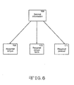
- the computer 56 may determine and communicate second information 168 to the tool 50 based on the first information 32.
- the second information 168 may comprise at least one of required torque 169, required swage force 170, required preload 171, or other types of information.
- the computer may determine, by accessing database 57, the appropriate torque 169, swage force 170, and/or preload 171 to apply to the fastener 18 and/or the collar, and may communicate that second information 168 to the tool 50.
- the fastener 18 and/or collar 21 may be fastened using the tool 50 based on the communicated second information 168. In such manner, the fastener 18 and/or collar 21 may be fastened with the appropriate torque 169, swage force 170, and/or preload 171 for that type of fastener 18 and/or collar 21.
- the tool 50 may communicate third information 174 to the computer 56. As shown in Figure 7 , which shows a block diagram showing the types of third information 174, the third information 174 may comprise an amount of at least one of torque 169A, preload 171A, and swage force 170A which the tool 50 actually applied to the fastener 18 and/or the collar 21 during installation.
- the computer 56 may store the third information 174 in database 57.
- Figure 8 shows a flowchart of an embodiment of one embodiment of a method 175 of tracking and monitoring a fastener 18 in an apparatus 16.
- a fastener 18 and a collar 21 may be provided attached at a location 17 of the apparatus 16.
- At least one of the fastener 18 and/or the collar 21 may have a code 30.
- the code 30 may be scanned and at least one of first information 32, second information 168, third information 174, and fourth information 178 regarding at least one of the fastener 18 and/or the collar 21 may be retrieved using a computer 56.
- Figure 9 which shows a block diagram showing the fourth information 178
- the fourth information 178 may comprise the location 17 of at least one of the fastener 18 and/or the collar 21.
- Figure 10 shows one embodiment of a method 179 of locating a fastener 18 in an apparatus 16.
- a fastener 18 and a collar 21 are provided attached at a location 17 of the apparatus 16.
- At least one of the fastener 18 and/or the collar 21 have a code 30.
- a computer 56 is provided having cross-linked to the code 30 at least one of first information 32, second information 168, third information 174, and fourth information 178 regarding at least one of the fastener 18 and/or the collar 21.
- at least two of the first information 32, second information 168, third information 174, and fourth information 178 are cross-linked in the computer 56.
- a location 17 of at least one of the fastener 18 and/or the collar 21 is determined using the computer 56.
- a fastening apparatus 10 may include at least one of a fastener 18 and/or a collar 21 having a code 30.
- the code 30 may be cross-linked in a database 57 of a computer 56 to at least one of first information 32, second information 168, third information 174, and fourth information 178 regarding the at least one fastener 18 and/or collar 21.
- One or more embodiments of the disclosure may reduce and/or eliminate one or more problems of one or more of the existing fastening apparatus and/or methods of installation, location, tracking, and/or monitoring.
- One or more embodiments of the disclosure may save time, may increase reliability, may decrease error, may improve efficiency, may reduce cost, and/or may reduce one or more other types of problems of one or more of the existing fastening apparatus and/or methods of installation, location, tracking, and/or monitoring.
Landscapes
- Engineering & Computer Science (AREA)
- Mechanical Engineering (AREA)
- Automatic Assembly (AREA)
- Connection Of Plates (AREA)
- Gasket Seals (AREA)
- Insertion Pins And Rivets (AREA)
Abstract
Description
- Many of the existing fasteners and/or fastener collars are not marked with any manufacture information such as part number, lot number, and manufacturer, and are often only marked with a supplier name. The manufacture information is often only carried by the package containing the batch of fasteners. When the package is opened, this information is often lost or has to be manually transferred to a manufacturing record. Many of the existing methods of verifying compatibility of fastener elements rely on the manual checking of a table to verify compatibility. Similarly, many of the existing methods of ensuring that the fasteners are installed correctly rely on manually checking tables to determine proper loading settings. Likewise, many of the existing methods of locating, tracking, and/or monitoring fasteners rely on the use of manual tables. However, manually entering and checking tables may be time-consuming, unreliable, expensive, prone to error, and/or may experience other types of problems.
- A fastening apparatus, and/or method of installing, locating, tracking, and/or monitoring a fastener is needed to decrease one or more problems associated with one or more of the existing fastening apparatus and/or methods.
- In one aspect of the disclosure, a method of installing a fastener comprises: (1) providing at least one of a fastener and a collar having a code; (2) scanning the code and retrieving first information regarding the at least one fastener and collar; (3) communicating the first information to a computer, the computer accessible to at least one database; (4) storing the first information in the at least one database; (5) communicating second information using the computer to a tool based on the first information; and (6) fastening the at least one fastener and collar using the second information and the tool.
- In another aspect of the disclosure, a method of tracking and monitoring a fastener in an apparatus is disclosed. In one step, at least one of a fastener and a collar is provided attached at a location of the apparatus. The at least one fastener and collar has a code. In another step, the code is scanned and at least one of first information, second information, third information, and fourth information regarding the at least one fastener and collar is retrieved using a computer.
- In still another aspect of the disclosure, a method of locating a fastener in an apparatus comprises: (1) providing at least one of a fastener and a collar having a code attached at a location of the apparatus; (2) providing a computer having cross-linked to the code at least one of first information, second information, third information, and fourth information regarding the at least one fastener and collar; and (3) determining a location of the at least one of fastener and collar using the computer.
- In still another aspect of the disclosure, a fastening apparatus is disclosed. The fastening apparatus includes at least one of a fastener and a collar having a code. The code is cross-linked in at least one database of a computer to at least one of first information, second information, third information, and fourth information regarding the at least one fastener and collar.
- These and other features, aspects and advantages of the disclosure will become better understood with reference to the following drawings, description and claims.
-
-
Figure 1 shows a perspective view, with dashed lines showing hidden elements, of one embodiment of a fastening apparatus being attached with a tool to two components of an apparatus; -
Figure 2 shows a side view of the fastener of the embodiment ofFigure 1 ; -
Figure 2A shows a top view of the fastener of the embodiment ofFigure 1 ; -
Figure 2B shows a block diagram showing various embodiments of the first information a code of the fastener may provide to a computer; -
Figure 3 shows a side view of the collar of the embodiment ofFigure 1 , with the dashed lines depicting hidden elements; -
Figure 3A shows a top view of the collar of the embodiment ofFigure 1 ; -
Figure 4 shows a side view of another embodiment of a collar which may be attached to the fastener of the embodiment ofFigure 1 , with the dashed lines depicting hidden elements; -
Figure 4A shows a top view of the collar of the embodiment ofFigure 4 ; -
Figure 5 shows a flowchart of one embodiment of a method of installing a fastener; -
Figure 6 shows a block diagram disclosing various embodiments of second information regarding the fastener and/or the collar which may be communicated from a computer to a tool; -
Figure 7 shows a block diagram disclosing various embodiments of third information regarding the fastener and/or the collar which may be communicated to a computer from a tool; -
Figure 8 shows a flowchart of an embodiment of one embodiment of a method of tracking and monitoring a fastener in an apparatus; -
Figure 9 shows a block diagram disclosing one embodiment of fourth information which a computer may contain regarding a fastener and/or a collar; and -
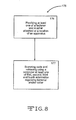
Figure 10 shows one embodiment of a method of locating a fastener in an apparatus. - The following detailed description is of the best currently contemplated modes of carrying out the disclosure. The description is not to be taken in a limiting sense, but is made merely for the purpose of illustrating the general principles of the disclosure, since the scope of the disclosure is best defined by the appended claims.
-
Figure 1 shows a perspective view, with dashed lines showing hidden elements, of one embodiment of afastening apparatus 10 being attached to twocomponents apparatus 16. Thefastening apparatus 10 may comprise at least one of afastener 18 andcollar 21. Thefastener 18 may comprise a one-piece fastener which may be attached without the use ofcollar 21, or may comprise a two-piece fastener which may be attached usingcollar 21. Thefastener 18 may comprise an externally threadedbolt 19 which is inserted at alocation 17 of theapparatus 16 through ahole 22 extending through the twocomponents collar 21 may comprise an internally threadednut 40 which screws onto thefastener 18 to lock thecomponents apparatus 10 together. Theapparatus 16, including itscomponents apparatus 16 may comprise varying non-aircraft applications. -
Figure 2 shows a side-view of thefastener 18 of the embodiment ofFigure 1 .Figure 2A shows a top view of thefastener 18 of the embodiment ofFigure 1 . As shown inFigures 2 and 2A , thefastener 18 may comprise abolt 19 having ahead 22,external threads 24, and anend surface 26. One ormore portions 28 of theend surface 26 may be marked with acode 30. Thecode 30 may compriselaser reader markings 32 or other types of markings.Figure 2B shows a block diagram showing the types of information thecode 30 of thefastener 18 may provide. As shown, thecode 30 may providefirst information 32 regarding thefastener 18 such assupplier identification 33,part number 34,lot number 35,batch number 36,material 37, type 38 (which may include size),date 39, and other types of information regarding thefastener 18. In other embodiments, thefastener 18 may be in varying shapes, sizes, orientations, and configurations, and thecode 30 may be on or in a varying portion of thefastener 18. -
Figure 3 shows a side-view of thecollar 21 of the embodiment ofFigure 1 , with the dashed lines depicting hidden elements.Figure 3A shows a top view of thecollar 21 of the embodiment ofFigure 1 . As shown inFigures 3 and 3A , thecollar 21 may comprise anut 40 having aflange 41,internal threads 42, and anend surface 43. One ormore portions 44 of theend surface 43 may be marked with acode 30. Thecode 30 may compriselaser reading markings 32 or other types of markings. Thecode 30 may provide the various types offirst information 32 shown inFigure 2B regarding thecollar 21. For instance, thecode 30 may providefirst information 32 regarding thecollar 21 such assupplier identification 33,part number 34,lot number 35,batch number 36,material 37, type 38 (which may include size),date 39, and other types of information regarding thecollar 21. In other embodiments, thecollar 21 may be in varying shapes, sizes, orientations, and configurations, and thecode 30 may be on or in a varying portion of thecollar 21. -
Figure 4 shows a side-view, with dashed lines depicting hidden elements, of another embodiment of acollar 21 comprising asleeve 45 which may be attached to thefastener 18 ofFigure 1 instead of thenut 40.Figure 4A shows a top view of thesleeve 45 of the embodiment ofFigure 4 . As shown inFigures 4 and 4A , thesleeve 45 may comprise aflange 46, internal threads 47 (which are shown in hidden lines), and anend surface 48. One ormore portions 49 of theend surface 48 may be marked with acode 30. Thecode 30 may compriselaser reading markings 32 or other types of markings. Thecode 30 may provide the various types offirst information 32 shown inFigure 2B regarding thesleeve 45. For instance, thecode 30 may providefirst information 32 regarding thesleeve 45 such assupplier identification 33,part number 34,lot number 35,batch number 36,material 37, type 38 (which may include size),date 39, and other types of information regarding thesleeve 45. In still other embodiments, thecollar 21 may be in varying shapes, sizes, orientations, and configurations, and thecode 30 may be on or in a varying portion of thecollar 21. - As shown in
Figure 1 , thecollar 21 may be screwed onto thefastener 18 using atool 50 such as a ratchet or other type oftool 50 which is adapted to screw thecollar 21 onto thefastener 18 to lock thecomponents fastener 18 may be fastened without the use ofcollar 21. Thetool 50 may have a smart chip 51 embedded within an outer surface 52 of thetool 50. An inner surface 53 defining a hole 54 may extend linearly from anend 59 of thetool 50. The inner surface 53 may be adapted to latch onto thecollar 21 to screw thecollar 21 onto thefastener 18. Alaser reader 55, such as an optical laser reader, may be disposed within the hole 54. Thelaser reader 55 may be adapted to scan and read thecode 30 of thefastener 18 and/or thecollar 21 in order to retrieve thefirst information 32 regarding thefastener 18 and/or thecollar 21. Thefirst information 32 may be stored in the smart chip 51. The smart chip 51 may be in wireless contact with acomputer 56 which has access and is in communication with one ormore databases 57. -
Figure 5 shows a flowchart of one embodiment of amethod 160 of installing afastener 18. In onestep 161, twocomponents components step 162, alocation 17 may be identified for installing afastener 18 to assemble the components. In anadditional step 162A, at least one of afastener 18 and acollar 21 may be provided. A one-piece fastener 18 may be used without acollar 21, or a two-piece fastener 18 may be used with acollar 18. Thefastener 18 may be abolt 19. Thecollar 21 may be anut 40 or asleeve 45. One or more of thefastener 18 and/or thecollar 21 may have acode 30 which may be one ormore laser markings 32. - In yet another
step 163, thecode 30 may be scanned andfirst information 32 may be retrieved regarding at least one of thefastener 18 and/or thecollar 21. Thecode 30 may be scanned using alaser reader 55 of atool 50. Thefirst information 32 may comprisesupplier identification 33,part number 34,lot number 35,batch number 36,material 37, type 38 (which may include size),date 39, and other types of information regarding thefastener 18 and/or thecollar 21. Thefirst information 32 scanned by thelaser reader 55 may be transferred to the smart chip 51 of thetool 50. - In an
additional step 164, thefirst information 32 may be communicated from the smart chip 51 of thetool 50 to acomputer 56. Thecomputer 56 may have access to one ormore databases 57. In yet anotherstep 165, thefirst information 32 may be stored in the one ormore databases 57 of thecomputer 56. Instep 166, if a two-piece fastener 18 is used with acollar 21, thecomputer 56 may determine based on thefirst information 32 whether thefastener 18 and thecollar 21 are compatible with one another. If thefastener 18 and thecollar 21 are not compatible, thecomputer 56 may send a signal to thetool 50 to not install thefastener 18 to thecollar 21. If thefastener 18 and thecollar 21 are compatible, thecomputer 56 may proceed to step 167. In other embodiments,step 166 may be skipped, and a determination may not be made as to compatibility. - In
step 167, thecomputer 56 may determine and communicatesecond information 168 to thetool 50 based on thefirst information 32. As shown inFigure 6 , which shows a block diagram showing the types ofsecond information 168, thesecond information 168 may comprise at least one of requiredtorque 169, requiredswage force 170, requiredpreload 171, or other types of information. In such manner, based on thefirst information 32 regarding thefastener 18 and/or thecollar 21, the computer may determine, by accessingdatabase 57, theappropriate torque 169,swage force 170, and/or preload 171 to apply to thefastener 18 and/or the collar, and may communicate thatsecond information 168 to thetool 50. - In still another
step 172, thefastener 18 and/orcollar 21 may be fastened using thetool 50 based on the communicatedsecond information 168. In such manner, thefastener 18 and/orcollar 21 may be fastened with theappropriate torque 169,swage force 170, and/or preload 171 for that type offastener 18 and/orcollar 21. In anadditional step 173, thetool 50 may communicatethird information 174 to thecomputer 56. As shown inFigure 7 , which shows a block diagram showing the types ofthird information 174, thethird information 174 may comprise an amount of at least one oftorque 169A, preload 171A, andswage force 170A which thetool 50 actually applied to thefastener 18 and/or thecollar 21 during installation. Thecomputer 56 may store thethird information 174 indatabase 57. -
Figure 8 shows a flowchart of an embodiment of one embodiment of amethod 175 of tracking and monitoring afastener 18 in anapparatus 16. In onestep 176, at least one of afastener 18 and acollar 21 may be provided attached at alocation 17 of theapparatus 16. At least one of thefastener 18 and/or thecollar 21 may have acode 30. In anotherstep 177, thecode 30 may be scanned and at least one offirst information 32,second information 168,third information 174, andfourth information 178 regarding at least one of thefastener 18 and/or thecollar 21 may be retrieved using acomputer 56. As shown inFigure 9 , which shows a block diagram showing thefourth information 178, thefourth information 178 may comprise thelocation 17 of at least one of thefastener 18 and/or thecollar 21. -
Figure 10 shows one embodiment of amethod 179 of locating afastener 18 in anapparatus 16. In onestep 180, at least one of afastener 18 and acollar 21 are provided attached at alocation 17 of theapparatus 16. At least one of thefastener 18 and/or thecollar 21 have acode 30. Instep 181, acomputer 56 is provided having cross-linked to thecode 30 at least one offirst information 32,second information 168,third information 174, andfourth information 178 regarding at least one of thefastener 18 and/or thecollar 21. In one embodiment, at least two of thefirst information 32,second information 168,third information 174, andfourth information 178 are cross-linked in thecomputer 56. Instep 182, alocation 17 of at least one of thefastener 18 and/or thecollar 21 is determined using thecomputer 56. - In another embodiment, as shown in
Figure 1 , afastening apparatus 10 may include at least one of afastener 18 and/or acollar 21 having acode 30. Thecode 30 may be cross-linked in adatabase 57 of acomputer 56 to at least one offirst information 32,second information 168,third information 174, andfourth information 178 regarding the at least onefastener 18 and/orcollar 21. - One or more embodiments of the disclosure may reduce and/or eliminate one or more problems of one or more of the existing fastening apparatus and/or methods of installation, location, tracking, and/or monitoring. One or more embodiments of the disclosure may save time, may increase reliability, may decrease error, may improve efficiency, may reduce cost, and/or may reduce one or more other types of problems of one or more of the existing fastening apparatus and/or methods of installation, location, tracking, and/or monitoring.
It should be understood, of course, that the foregoing relates to exemplary embodiments of the disclosure and that modifications may be made without departing from the spirit and scope of the disclosure as set forth in the following claims.
Claims (13)
- A method of installing a fastener comprising:providing at least one of a fastener and a collar having a code;scanning the code and retrieving first information regarding said at least one fastener and collar;communicating the first information to a computer, the computer accessible to at least one database;storing the first information in the at least one database;communicating second information using the computer to a tool based on the first information; andfastening said at least one fastener and collar using the second information and the tool.
- The method of claim 1 further comprising at least one of the steps of providing two components, identifying a location for installing the fastener to assemble the two components, and inserting the fastener through a hole extending within the two components.
- The method of claim 1 wherein the code is a laser marking.
- The method of claim 1 wherein the first information is at least one of supplier identification, part number, lot number, batch number, material, type, size, and date.
- The method of claim 1 wherein the second information is at least one of required torque, required swage force, and required preload.
- The method of claim 1 further comprising the tool communicating third information to the computer, wherein the third information comprises an amount of at least one of torque, preload, and swage force which the tool applied to the at least one fastener and collar, and the computer storing said at least one applied torque, preload, and swage force in the at least one database.
- A method of tracking and monitoring a fastener in an apparatus comprising:providing at least one of a fastener and a collar having a code attached at a location of the apparatus; andscanning the code and retrieving using a computer at least one of first information, second information, third information, and fourth information regarding the at least one fastener and collar.
- The method of claim 7 wherein the code is a laser marking.
- The method of claim 7 wherein the first information is at least one of supplier identification, part number, lot number, batch number, material, type, and date.
- A method of locating a fastener in an apparatus comprising:providing at least one of a fastener and a collar having a code attached at a location of the apparatus;providing a computer having cross-linked to the code at least one of first information, second information, third information, and fourth information regarding the at least one fastener and collar; anddetermining a location of the at least one fastener and collar using the computer.
- The method of claim 10 wherein the first information is at least one of supplier identification, part number, lot number, batch number, material, type, and date, the second information is at least one of torque, swage force, and preload which should have been applied to the at least one fastener and collar, the third information is at least one of torque, swage force, and preload which was applied to the at least one fastener and collar, and the fourth information is the location of the at least one fastener and collar.
- A fastening apparatus comprising:at least one of a fastener and a collar having a code, wherein the code is cross-linked in at least one database of a computer to at least one of first information, second information, third information, and fourth information regarding the at least one fastener and collar.
- The fastening apparatus of claim 12 wherein the first information is at least one of supplier identification, part number, lot number, batch number, material, type, and date, the second information is at least one of torque, swage force, and preload which should have been applied to the at least one fastener and collar, the third information is at least one of torque, swage force, and preload which was applied to the at least one fastener and collar, and the fourth information is the location of the at least one fastener and collar.
Applications Claiming Priority (1)
| Application Number | Priority Date | Filing Date | Title |
|---|---|---|---|
| US11/931,628 US7703669B2 (en) | 2007-10-31 | 2007-10-31 | Intelligent fastener installation system |
Publications (3)
| Publication Number | Publication Date |
|---|---|
| EP2058530A2 true EP2058530A2 (en) | 2009-05-13 |
| EP2058530A3 EP2058530A3 (en) | 2009-05-20 |
| EP2058530B1 EP2058530B1 (en) | 2018-05-23 |
Family
ID=40509552
Family Applications (1)
| Application Number | Title | Priority Date | Filing Date |
|---|---|---|---|
| EP08253538.6A Active EP2058530B1 (en) | 2007-10-31 | 2008-10-29 | Intelligent fastener installation system |
Country Status (6)
| Country | Link |
|---|---|
| US (1) | US7703669B2 (en) |
| EP (1) | EP2058530B1 (en) |
| JP (1) | JP5366501B2 (en) |
| CN (1) | CN101425240B (en) |
| CA (1) | CA2641780C (en) |
| ES (1) | ES2684383T3 (en) |
Cited By (5)
| Publication number | Priority date | Publication date | Assignee | Title |
|---|---|---|---|---|
| CN102114717A (en) * | 2011-01-24 | 2011-07-06 | 奇瑞汽车股份有限公司 | Fixed detection device and method for upper die of pressing machine |
| GB2511591A (en) * | 2013-03-05 | 2014-09-10 | Hitachi Ltd | Operation management system and operation management method |
| TWI490070B (en) * | 2013-02-01 | 2015-07-01 | ||
| EP2908014A1 (en) * | 2014-02-13 | 2015-08-19 | HALFEN GmbH | Screw |
| EP3760883A1 (en) | 2019-07-03 | 2021-01-06 | Hilti Aktiengesellschaft | Screw nut with barcode pattern segments |
Families Citing this family (44)
| Publication number | Priority date | Publication date | Assignee | Title |
|---|---|---|---|---|
| US8978967B2 (en) * | 2007-10-31 | 2015-03-17 | The Boeing Campany | Intelligent fastener system |
| US8521448B1 (en) | 2009-10-21 | 2013-08-27 | The Boeing Company | Structural analysis using measurement of fastener parameters |
| US8810370B2 (en) | 2010-01-22 | 2014-08-19 | The Boeing Company | Wireless collection of fastener data |
| US8683869B2 (en) * | 2008-09-04 | 2014-04-01 | The Boeing Company | Monitoring fastener preload |
| CN101890472B (en) * | 2009-05-22 | 2012-11-28 | 中国气动工业股份有限公司 | Digital display module device for nail puller and cap puller gun |
| US8255070B2 (en) * | 2009-10-07 | 2012-08-28 | The Boeing Company | Method and apparatus for establishing a camera focal length for installing fasteners |
| JP2011230254A (en) * | 2010-04-28 | 2011-11-17 | Asahi Electric Works Ltd | Bolt axial force control system |
| JP5559338B2 (en) * | 2010-09-16 | 2014-07-23 | 株式会社東芝 | Light emitting device and LED bulb |
| KR101833407B1 (en) * | 2010-11-15 | 2018-02-28 | 하이토크 디비젼 유넥스 코포레이션 | Drive unit for a power operated tool |
| US9026242B2 (en) | 2011-05-19 | 2015-05-05 | Taktia Llc | Automatically guided tools |
| US8448520B1 (en) | 2011-12-06 | 2013-05-28 | King Fahd University Of Petroleum And Minerals | Bolt tension monitoring system |
| JP5930708B2 (en) * | 2011-12-27 | 2016-06-08 | 三菱電機エンジニアリング株式会社 | Work management device and work management system |
| US8584957B2 (en) * | 2012-01-23 | 2013-11-19 | Silicon Valley Microe Corp. | Intelligent fastener |
| US10556356B2 (en) | 2012-04-26 | 2020-02-11 | Sharper Tools, Inc. | Systems and methods for performing a task on a material, or locating the position of a device relative to the surface of the material |
| US9862077B2 (en) | 2012-04-30 | 2018-01-09 | The Boeing Company | System, an apparatus and a method for laser projection-assisted fastener installation |
| DE102012105654A1 (en) * | 2012-06-28 | 2014-01-02 | Jörg Hohmann | Clamping device for stretching a threaded bolt |
| DE102012106503B4 (en) * | 2012-07-18 | 2023-03-16 | Jörg Hohmann | Clamping device for stretching a threaded bolt |
| US20150316919A1 (en) * | 2013-05-16 | 2015-11-05 | HYTORC Division Unex Corporation | Multifunctional Hydraulic Drive Unit |
| TWI551783B (en) * | 2013-05-16 | 2016-10-01 | 矽谷微電子股份有限公司 | Intelligent fastener, and fastener installation and inspection system |
| CN104179771B (en) * | 2013-05-23 | 2017-08-29 | 硅谷微E股份有限公司 | Intelligent fastener and fastener are installed and inspection system |
| US9915574B2 (en) | 2014-03-11 | 2018-03-13 | The Boeing Company | Method and apparatus for measuring a preload of a fastener |
| FR3029818B1 (en) * | 2014-12-11 | 2017-01-13 | Aerolia | METHOD FOR CRIMPING A RING ON A FASTENING ROD BY AN AUTOMATE |
| US10592772B2 (en) | 2015-03-27 | 2020-03-17 | Nec Corporation | Image capturing attachment tool, work management method, system, comparison device, and program |
| EP3294503B1 (en) | 2015-05-13 | 2020-01-29 | Shaper Tools, Inc. | Systems, methods and apparatus for guided tools |
| CN105171397A (en) * | 2015-08-28 | 2015-12-23 | 芜湖天海电装有限公司 | Bolt tightening and torque forced verification mechanism for vehicle wire harnesses and parts thereof |
| CN109643098B (en) | 2016-08-19 | 2022-06-03 | 整形工具股份有限公司 | System, method and medium for tracking use of a drilling rig |
| EP3563946B1 (en) * | 2016-12-28 | 2021-11-03 | Makita Corporation | Fastening tool |
| US11560015B2 (en) | 2017-09-22 | 2023-01-24 | Consolidated Metco, Inc. | Wheel hub |
| SG11202005033UA (en) * | 2017-12-08 | 2020-06-29 | Connectec Japan Corp | Tool, task management device, task management method, and task management system |
| CN108131374A (en) * | 2017-12-18 | 2018-06-08 | 河南航天精工制造有限公司 | Fastener and bolt are installed in mistake proofing |
| WO2019152689A2 (en) | 2018-01-31 | 2019-08-08 | Abb Schweiz Ag | Crimping tool with wireless communication system |
| DE102018111652A1 (en) * | 2018-05-15 | 2019-11-21 | STAHLWILLE Eduard Wille GmbH & Co. KG | Tool and method for operating a tool |
| WO2020106942A1 (en) | 2018-11-21 | 2020-05-28 | Consolidated Metco, Inc. | Wheel end apparatus with electric generator |
| CN109909927B (en) * | 2019-03-03 | 2021-03-23 | 陕西理工大学 | High-safety self-separating intelligent torque wrench and using method thereof |
| GB2582940B (en) * | 2019-04-09 | 2021-04-07 | Star Fasteners Uk Ltd | Swaged fasteners |
| US10938447B1 (en) * | 2019-08-08 | 2021-03-02 | The Boeing Company | Radio-frequency-identification-based smart fastener |
| WO2021072110A1 (en) | 2019-10-09 | 2021-04-15 | Consolidated Metco, Inc. | Wheel end monitoring apparatus, fastener, and method |
| US11491533B2 (en) * | 2019-12-18 | 2022-11-08 | Spirit Aerosystems, Inc. | Fastener insertion gun for installing fasteners in vehicle structures |
| US11370073B2 (en) * | 2019-12-18 | 2022-06-28 | Spirit Aerosystems, Inc. | System and method for drilling holes and installing fasteners in vehicle structures |
| US12420330B2 (en) | 2019-12-18 | 2025-09-23 | Spirit Aerosystems, Inc. | System and method for drilling holes and installing fasteners in vehicle structures |
| WO2021126733A1 (en) * | 2019-12-18 | 2021-06-24 | Spirit Aerosystems, Inc. | System and method for drilling holes and installing fasteners in vehicle structures |
| CN114571400A (en) * | 2020-12-01 | 2022-06-03 | 宝能汽车集团有限公司 | Integrated system of torque wrench and torque wrench |
| CN114559244B (en) * | 2021-12-03 | 2026-01-13 | 陕西优耐特机械有限公司 | Screw assembly system for reprocessing circumferential screw holes |
| CN115070661B (en) * | 2022-07-19 | 2024-07-16 | 重庆大学 | Intelligent control and monitoring system for bolt tightening load and its application method |
Citations (2)
| Publication number | Priority date | Publication date | Assignee | Title |
|---|---|---|---|---|
| DE19917222A1 (en) | 1999-04-16 | 2000-11-02 | Schrauben Betzer Gmbh & Co Kg | Screw and device for handling such a screw |
| EP1188521A2 (en) | 2000-09-16 | 2002-03-20 | HILTI Aktiengesellschaft | Powered tool with torque control |
Family Cites Families (10)
| Publication number | Priority date | Publication date | Assignee | Title |
|---|---|---|---|---|
| US5448846A (en) * | 1992-04-09 | 1995-09-12 | Precision Dynamics Corporation | Identification device for machine imprinting |
| JPH0899238A (en) * | 1994-09-30 | 1996-04-16 | Hino Motors Ltd | Nut washer feeder, bolt nut combination work robot and bolt nut assembly work robot |
| US6095739A (en) * | 1998-07-02 | 2000-08-01 | Albertson; Stephen H. | Categorizing fasteners and construction connectors using visual identifiers |
| US6073552A (en) * | 1998-03-16 | 2000-06-13 | Sps Technologies | Method of fastener identification by impressing characters into a surface |
| US20040067120A1 (en) * | 2002-10-07 | 2004-04-08 | Speer Brian William | Mechanical fasteners with individual indicia of their size and/or other characteristics |
| JP2005177919A (en) * | 2003-12-19 | 2005-07-07 | Yamaha Motor Co Ltd | Work tool and work system using the same |
| JP4271679B2 (en) * | 2005-09-26 | 2009-06-03 | 本田技研工業株式会社 | Assembly management system and program |
| US7412898B1 (en) * | 2006-07-28 | 2008-08-19 | Disney Enterprises, Inc. | Load sensing system including RFID tagged fasteners |
| US20080178713A1 (en) * | 2007-01-31 | 2008-07-31 | Robert Earl Long | Fastener tightening system utilizing identification technology |
| JP5065851B2 (en) * | 2007-10-19 | 2012-11-07 | 株式会社日立製作所 | Work management system |
-
2007
- 2007-10-31 US US11/931,628 patent/US7703669B2/en active Active
-
2008
- 2008-10-23 CA CA2641780A patent/CA2641780C/en active Active
- 2008-10-29 ES ES08253538.6T patent/ES2684383T3/en active Active
- 2008-10-29 EP EP08253538.6A patent/EP2058530B1/en active Active
- 2008-10-31 CN CN200810171018.2A patent/CN101425240B/en active Active
- 2008-10-31 JP JP2008281205A patent/JP5366501B2/en active Active
Patent Citations (2)
| Publication number | Priority date | Publication date | Assignee | Title |
|---|---|---|---|---|
| DE19917222A1 (en) | 1999-04-16 | 2000-11-02 | Schrauben Betzer Gmbh & Co Kg | Screw and device for handling such a screw |
| EP1188521A2 (en) | 2000-09-16 | 2002-03-20 | HILTI Aktiengesellschaft | Powered tool with torque control |
Cited By (8)
| Publication number | Priority date | Publication date | Assignee | Title |
|---|---|---|---|---|
| CN102114717A (en) * | 2011-01-24 | 2011-07-06 | 奇瑞汽车股份有限公司 | Fixed detection device and method for upper die of pressing machine |
| CN102114717B (en) * | 2011-01-24 | 2013-07-17 | 奇瑞汽车股份有限公司 | Fixed detection device and method for upper die of pressing machine |
| TWI490070B (en) * | 2013-02-01 | 2015-07-01 | ||
| GB2511591A (en) * | 2013-03-05 | 2014-09-10 | Hitachi Ltd | Operation management system and operation management method |
| GB2511591B (en) * | 2013-03-05 | 2015-02-11 | Hitachi Ltd | Operation management system for displaying position information of target components |
| EP2908014A1 (en) * | 2014-02-13 | 2015-08-19 | HALFEN GmbH | Screw |
| EP3760883A1 (en) | 2019-07-03 | 2021-01-06 | Hilti Aktiengesellschaft | Screw nut with barcode pattern segments |
| WO2021001214A1 (en) * | 2019-07-03 | 2021-01-07 | Hilti Aktiengesellschaft | Screw nut with barcode pattern segments |
Also Published As
| Publication number | Publication date |
|---|---|
| JP2009107114A (en) | 2009-05-21 |
| CA2641780C (en) | 2012-12-18 |
| US20090112925A1 (en) | 2009-04-30 |
| ES2684383T3 (en) | 2018-10-02 |
| EP2058530B1 (en) | 2018-05-23 |
| US7703669B2 (en) | 2010-04-27 |
| CN101425240B (en) | 2014-03-19 |
| CA2641780A1 (en) | 2009-04-30 |
| JP5366501B2 (en) | 2013-12-11 |
| CN101425240A (en) | 2009-05-06 |
| EP2058530A3 (en) | 2009-05-20 |
Similar Documents
| Publication | Publication Date | Title |
|---|---|---|
| US7703669B2 (en) | Intelligent fastener installation system | |
| US8978967B2 (en) | Intelligent fastener system | |
| JP2014225075A (en) | Intelligent fastener | |
| US10596985B2 (en) | Operating method for a filter system and filter system | |
| US6499714B1 (en) | System for and method of mounting compressors | |
| US20140345110A1 (en) | Anchor system, in particular undercut anchor system | |
| US7080461B2 (en) | Installation tool for aerospace fastening system | |
| CN101005920B (en) | Method and apparatus for locating and aligning fasteners | |
| US20220063068A1 (en) | Rfid/nfc enabled fittings, smart torque tool system, and torque sensing fitting | |
| US6074147A (en) | Tamper-proof set screw | |
| CN113643252B (en) | Screw torque force determining method and torque wrench for vehicle | |
| US8348570B2 (en) | Mounting apparatus for heat sink and fastening assembly of the mounting apparatus | |
| US20180169844A1 (en) | Fastener labeling device and method | |
| US6988314B2 (en) | Assembly, tolerance matching and post-manufacturing quality assurance method | |
| US20050159856A1 (en) | Method and system for exchanging data between control devices | |
| TWI551783B (en) | Intelligent fastener, and fastener installation and inspection system | |
| US7152139B1 (en) | Techniques for generating serial presence detect contents | |
| US11845569B2 (en) | Eddie-bolt inspection tool | |
| US20050177990A1 (en) | Swage collar inspection tool and method | |
| HK40114448A (en) | Rail system and method for testing same | |
| CN112099811B (en) | Method and device for installing rpm package | |
| US20080183795A1 (en) | Automated fastener data management system | |
| CN118401950A (en) | Guide rail system and method for checking a guide rail system | |
| DK201970786A1 (en) | Bolt tag system | |
| JP2004151852A (en) | Quality control method and apparatus for thin steel products |
Legal Events
| Date | Code | Title | Description |
|---|---|---|---|
| PUAI | Public reference made under article 153(3) epc to a published international application that has entered the european phase |
Free format text: ORIGINAL CODE: 0009012 |
|
| PUAL | Search report despatched |
Free format text: ORIGINAL CODE: 0009013 |
|
| 17P | Request for examination filed |
Effective date: 20081114 |
|
| AK | Designated contracting states |
Kind code of ref document: A2 Designated state(s): AT BE BG CH CY CZ DE DK EE ES FI FR GB GR HR HU IE IS IT LI LT LU LV MC MT NL NO PL PT RO SE SI SK TR |
|
| AX | Request for extension of the european patent |
Extension state: AL BA MK RS |
|
| AK | Designated contracting states |
Kind code of ref document: A3 Designated state(s): AT BE BG CH CY CZ DE DK EE ES FI FR GB GR HR HU IE IS IT LI LT LU LV MC MT NL NO PL PT RO SE SI SK TR |
|
| AX | Request for extension of the european patent |
Extension state: AL BA MK RS |
|
| 17Q | First examination report despatched |
Effective date: 20091210 |
|
| AKX | Designation fees paid |
Designated state(s): AT BE BG CH CY CZ DE DK EE ES FI FR GB GR HR HU IE IS IT LI LT LU LV MC MT NL NO PL PT RO SE SI SK TR |
|
| GRAP | Despatch of communication of intention to grant a patent |
Free format text: ORIGINAL CODE: EPIDOSNIGR1 |
|
| INTG | Intention to grant announced |
Effective date: 20171206 |
|
| RIN1 | Information on inventor provided before grant (corrected) |
Inventor name: SARH, BRANKO Inventor name: AMIREHTESHAMI, DAVID H. Inventor name: ZANTESON, WILLIAM P |
|
| GRAS | Grant fee paid |
Free format text: ORIGINAL CODE: EPIDOSNIGR3 |
|
| GRAA | (expected) grant |
Free format text: ORIGINAL CODE: 0009210 |
|
| AK | Designated contracting states |
Kind code of ref document: B1 Designated state(s): AT BE BG CH CY CZ DE DK EE ES FI FR GB GR HR HU IE IS IT LI LT LU LV MC MT NL NO PL PT RO SE SI SK TR |
|
| REG | Reference to a national code |
Ref country code: GB Ref legal event code: FG4D |
|
| REG | Reference to a national code |
Ref country code: CH Ref legal event code: EP |
|
| REG | Reference to a national code |
Ref country code: IE Ref legal event code: FG4D |
|
| REG | Reference to a national code |
Ref country code: DE Ref legal event code: R096 Ref document number: 602008055338 Country of ref document: DE |
|
| REG | Reference to a national code |
Ref country code: AT Ref legal event code: REF Ref document number: 1001748 Country of ref document: AT Kind code of ref document: T Effective date: 20180615 |
|
| REG | Reference to a national code |
Ref country code: NL Ref legal event code: MP Effective date: 20180523 |
|
| REG | Reference to a national code |
Ref country code: ES Ref legal event code: FG2A Ref document number: 2684383 Country of ref document: ES Kind code of ref document: T3 Effective date: 20181002 |
|
| REG | Reference to a national code |
Ref country code: LT Ref legal event code: MG4D |
|
| REG | Reference to a national code |
Ref country code: FR Ref legal event code: PLFP Year of fee payment: 11 |
|
| PG25 | Lapsed in a contracting state [announced via postgrant information from national office to epo] |
Ref country code: FI Free format text: LAPSE BECAUSE OF FAILURE TO SUBMIT A TRANSLATION OF THE DESCRIPTION OR TO PAY THE FEE WITHIN THE PRESCRIBED TIME-LIMIT Effective date: 20180523 Ref country code: BG Free format text: LAPSE BECAUSE OF FAILURE TO SUBMIT A TRANSLATION OF THE DESCRIPTION OR TO PAY THE FEE WITHIN THE PRESCRIBED TIME-LIMIT Effective date: 20180823 Ref country code: NO Free format text: LAPSE BECAUSE OF FAILURE TO SUBMIT A TRANSLATION OF THE DESCRIPTION OR TO PAY THE FEE WITHIN THE PRESCRIBED TIME-LIMIT Effective date: 20180823 Ref country code: SE Free format text: LAPSE BECAUSE OF FAILURE TO SUBMIT A TRANSLATION OF THE DESCRIPTION OR TO PAY THE FEE WITHIN THE PRESCRIBED TIME-LIMIT Effective date: 20180523 Ref country code: LT Free format text: LAPSE BECAUSE OF FAILURE TO SUBMIT A TRANSLATION OF THE DESCRIPTION OR TO PAY THE FEE WITHIN THE PRESCRIBED TIME-LIMIT Effective date: 20180523 |
|
| PG25 | Lapsed in a contracting state [announced via postgrant information from national office to epo] |
Ref country code: LV Free format text: LAPSE BECAUSE OF FAILURE TO SUBMIT A TRANSLATION OF THE DESCRIPTION OR TO PAY THE FEE WITHIN THE PRESCRIBED TIME-LIMIT Effective date: 20180523 Ref country code: HR Free format text: LAPSE BECAUSE OF FAILURE TO SUBMIT A TRANSLATION OF THE DESCRIPTION OR TO PAY THE FEE WITHIN THE PRESCRIBED TIME-LIMIT Effective date: 20180523 Ref country code: NL Free format text: LAPSE BECAUSE OF FAILURE TO SUBMIT A TRANSLATION OF THE DESCRIPTION OR TO PAY THE FEE WITHIN THE PRESCRIBED TIME-LIMIT Effective date: 20180523 Ref country code: GR Free format text: LAPSE BECAUSE OF FAILURE TO SUBMIT A TRANSLATION OF THE DESCRIPTION OR TO PAY THE FEE WITHIN THE PRESCRIBED TIME-LIMIT Effective date: 20180824 |
|
| REG | Reference to a national code |
Ref country code: AT Ref legal event code: MK05 Ref document number: 1001748 Country of ref document: AT Kind code of ref document: T Effective date: 20180523 |
|
| PG25 | Lapsed in a contracting state [announced via postgrant information from national office to epo] |
Ref country code: PL Free format text: LAPSE BECAUSE OF FAILURE TO SUBMIT A TRANSLATION OF THE DESCRIPTION OR TO PAY THE FEE WITHIN THE PRESCRIBED TIME-LIMIT Effective date: 20180523 Ref country code: EE Free format text: LAPSE BECAUSE OF FAILURE TO SUBMIT A TRANSLATION OF THE DESCRIPTION OR TO PAY THE FEE WITHIN THE PRESCRIBED TIME-LIMIT Effective date: 20180523 Ref country code: DK Free format text: LAPSE BECAUSE OF FAILURE TO SUBMIT A TRANSLATION OF THE DESCRIPTION OR TO PAY THE FEE WITHIN THE PRESCRIBED TIME-LIMIT Effective date: 20180523 Ref country code: RO Free format text: LAPSE BECAUSE OF FAILURE TO SUBMIT A TRANSLATION OF THE DESCRIPTION OR TO PAY THE FEE WITHIN THE PRESCRIBED TIME-LIMIT Effective date: 20180523 Ref country code: AT Free format text: LAPSE BECAUSE OF FAILURE TO SUBMIT A TRANSLATION OF THE DESCRIPTION OR TO PAY THE FEE WITHIN THE PRESCRIBED TIME-LIMIT Effective date: 20180523 Ref country code: CZ Free format text: LAPSE BECAUSE OF FAILURE TO SUBMIT A TRANSLATION OF THE DESCRIPTION OR TO PAY THE FEE WITHIN THE PRESCRIBED TIME-LIMIT Effective date: 20180523 Ref country code: SK Free format text: LAPSE BECAUSE OF FAILURE TO SUBMIT A TRANSLATION OF THE DESCRIPTION OR TO PAY THE FEE WITHIN THE PRESCRIBED TIME-LIMIT Effective date: 20180523 |
|
| REG | Reference to a national code |
Ref country code: DE Ref legal event code: R097 Ref document number: 602008055338 Country of ref document: DE |
|
| PLBE | No opposition filed within time limit |
Free format text: ORIGINAL CODE: 0009261 |
|
| STAA | Information on the status of an ep patent application or granted ep patent |
Free format text: STATUS: NO OPPOSITION FILED WITHIN TIME LIMIT |
|
| 26N | No opposition filed |
Effective date: 20190226 |
|
| PG25 | Lapsed in a contracting state [announced via postgrant information from national office to epo] |
Ref country code: SI Free format text: LAPSE BECAUSE OF FAILURE TO SUBMIT A TRANSLATION OF THE DESCRIPTION OR TO PAY THE FEE WITHIN THE PRESCRIBED TIME-LIMIT Effective date: 20180523 |
|
| REG | Reference to a national code |
Ref country code: CH Ref legal event code: PL |
|
| REG | Reference to a national code |
Ref country code: BE Ref legal event code: MM Effective date: 20181031 |
|
| PG25 | Lapsed in a contracting state [announced via postgrant information from national office to epo] |
Ref country code: MC Free format text: LAPSE BECAUSE OF FAILURE TO SUBMIT A TRANSLATION OF THE DESCRIPTION OR TO PAY THE FEE WITHIN THE PRESCRIBED TIME-LIMIT Effective date: 20180523 Ref country code: LU Free format text: LAPSE BECAUSE OF NON-PAYMENT OF DUE FEES Effective date: 20181029 |
|
| REG | Reference to a national code |
Ref country code: IE Ref legal event code: MM4A |
|
| PG25 | Lapsed in a contracting state [announced via postgrant information from national office to epo] |
Ref country code: BE Free format text: LAPSE BECAUSE OF NON-PAYMENT OF DUE FEES Effective date: 20181031 Ref country code: LI Free format text: LAPSE BECAUSE OF NON-PAYMENT OF DUE FEES Effective date: 20181031 Ref country code: CH Free format text: LAPSE BECAUSE OF NON-PAYMENT OF DUE FEES Effective date: 20181031 |
|
| PG25 | Lapsed in a contracting state [announced via postgrant information from national office to epo] |
Ref country code: IE Free format text: LAPSE BECAUSE OF NON-PAYMENT OF DUE FEES Effective date: 20181029 |
|
| REG | Reference to a national code |
Ref country code: DE Ref legal event code: R082 Ref document number: 602008055338 Country of ref document: DE Representative=s name: MAIER, LL.M., MICHAEL C., DE Ref country code: DE Ref legal event code: R082 Ref document number: 602008055338 Country of ref document: DE Representative=s name: BOULT WADE TENNANT LLP, DE |
|
| PG25 | Lapsed in a contracting state [announced via postgrant information from national office to epo] |
Ref country code: MT Free format text: LAPSE BECAUSE OF NON-PAYMENT OF DUE FEES Effective date: 20181029 |
|
| REG | Reference to a national code |
Ref country code: DE Ref legal event code: R082 Ref document number: 602008055338 Country of ref document: DE Representative=s name: BOULT WADE TENNANT LLP, DE |
|
| PG25 | Lapsed in a contracting state [announced via postgrant information from national office to epo] |
Ref country code: TR Free format text: LAPSE BECAUSE OF FAILURE TO SUBMIT A TRANSLATION OF THE DESCRIPTION OR TO PAY THE FEE WITHIN THE PRESCRIBED TIME-LIMIT Effective date: 20180523 |
|
| PG25 | Lapsed in a contracting state [announced via postgrant information from national office to epo] |
Ref country code: PT Free format text: LAPSE BECAUSE OF FAILURE TO SUBMIT A TRANSLATION OF THE DESCRIPTION OR TO PAY THE FEE WITHIN THE PRESCRIBED TIME-LIMIT Effective date: 20180523 |
|
| PG25 | Lapsed in a contracting state [announced via postgrant information from national office to epo] |
Ref country code: HU Free format text: LAPSE BECAUSE OF FAILURE TO SUBMIT A TRANSLATION OF THE DESCRIPTION OR TO PAY THE FEE WITHIN THE PRESCRIBED TIME-LIMIT; INVALID AB INITIO Effective date: 20081029 Ref country code: CY Free format text: LAPSE BECAUSE OF FAILURE TO SUBMIT A TRANSLATION OF THE DESCRIPTION OR TO PAY THE FEE WITHIN THE PRESCRIBED TIME-LIMIT Effective date: 20180523 |
|
| PG25 | Lapsed in a contracting state [announced via postgrant information from national office to epo] |
Ref country code: IS Free format text: LAPSE BECAUSE OF FAILURE TO SUBMIT A TRANSLATION OF THE DESCRIPTION OR TO PAY THE FEE WITHIN THE PRESCRIBED TIME-LIMIT Effective date: 20180923 |
|
| P01 | Opt-out of the competence of the unified patent court (upc) registered |
Effective date: 20230516 |
|
| PGFP | Annual fee paid to national office [announced via postgrant information from national office to epo] |
Ref country code: DE Payment date: 20251029 Year of fee payment: 18 |
|
| PGFP | Annual fee paid to national office [announced via postgrant information from national office to epo] |
Ref country code: GB Payment date: 20251027 Year of fee payment: 18 |
|
| PGFP | Annual fee paid to national office [announced via postgrant information from national office to epo] |
Ref country code: IT Payment date: 20251021 Year of fee payment: 18 |
|
| PGFP | Annual fee paid to national office [announced via postgrant information from national office to epo] |
Ref country code: FR Payment date: 20251027 Year of fee payment: 18 |
|
| PGFP | Annual fee paid to national office [announced via postgrant information from national office to epo] |
Ref country code: ES Payment date: 20251103 Year of fee payment: 18 |