EP2058511A1 - Fuel injector with fuel pressure sensor - Google Patents
Fuel injector with fuel pressure sensor Download PDFInfo
- Publication number
- EP2058511A1 EP2058511A1 EP08168397A EP08168397A EP2058511A1 EP 2058511 A1 EP2058511 A1 EP 2058511A1 EP 08168397 A EP08168397 A EP 08168397A EP 08168397 A EP08168397 A EP 08168397A EP 2058511 A1 EP2058511 A1 EP 2058511A1
- Authority
- EP
- European Patent Office
- Prior art keywords
- fuel
- pressure
- injector
- circuit component
- pressure sensor
- Prior art date
- Legal status (The legal status is an assumption and is not a legal conclusion. Google has not performed a legal analysis and makes no representation as to the accuracy of the status listed.)
- Granted
Links
Images

Classifications
-
- F—MECHANICAL ENGINEERING; LIGHTING; HEATING; WEAPONS; BLASTING
- F02—COMBUSTION ENGINES; HOT-GAS OR COMBUSTION-PRODUCT ENGINE PLANTS
- F02M—SUPPLYING COMBUSTION ENGINES IN GENERAL WITH COMBUSTIBLE MIXTURES OR CONSTITUENTS THEREOF
- F02M65/00—Testing fuel-injection apparatus, e.g. testing injection timing ; Cleaning of fuel-injection apparatus
- F02M65/003—Measuring variation of fuel pressure in high pressure line
-
- F—MECHANICAL ENGINEERING; LIGHTING; HEATING; WEAPONS; BLASTING
- F02—COMBUSTION ENGINES; HOT-GAS OR COMBUSTION-PRODUCT ENGINE PLANTS
- F02M—SUPPLYING COMBUSTION ENGINES IN GENERAL WITH COMBUSTIBLE MIXTURES OR CONSTITUENTS THEREOF
- F02M47/00—Fuel-injection apparatus operated cyclically with fuel-injection valves actuated by fluid pressure
- F02M47/02—Fuel-injection apparatus operated cyclically with fuel-injection valves actuated by fluid pressure of accumulator-injector type, i.e. having fuel pressure of accumulator tending to open, and fuel pressure in other chamber tending to close, injection valves and having means for periodically releasing that closing pressure
- F02M47/027—Electrically actuated valves draining the chamber to release the closing pressure
-
- F—MECHANICAL ENGINEERING; LIGHTING; HEATING; WEAPONS; BLASTING
- F02—COMBUSTION ENGINES; HOT-GAS OR COMBUSTION-PRODUCT ENGINE PLANTS
- F02M—SUPPLYING COMBUSTION ENGINES IN GENERAL WITH COMBUSTIBLE MIXTURES OR CONSTITUENTS THEREOF
- F02M57/00—Fuel-injectors combined or associated with other devices
- F02M57/005—Fuel-injectors combined or associated with other devices the devices being sensors
-
- G—PHYSICS
- G01—MEASURING; TESTING
- G01L—MEASURING FORCE, STRESS, TORQUE, WORK, MECHANICAL POWER, MECHANICAL EFFICIENCY, OR FLUID PRESSURE
- G01L23/00—Devices or apparatus for measuring or indicating or recording rapid changes, such as oscillations, in the pressure of steam, gas, or liquid; Indicators for determining work or energy of steam, internal-combustion, or other fluid-pressure engines from the condition of the working fluid
- G01L23/22—Devices or apparatus for measuring or indicating or recording rapid changes, such as oscillations, in the pressure of steam, gas, or liquid; Indicators for determining work or energy of steam, internal-combustion, or other fluid-pressure engines from the condition of the working fluid for detecting or indicating knocks in internal-combustion engines; Units comprising pressure-sensitive members combined with ignitors for firing internal-combustion engines
-
- F—MECHANICAL ENGINEERING; LIGHTING; HEATING; WEAPONS; BLASTING
- F02—COMBUSTION ENGINES; HOT-GAS OR COMBUSTION-PRODUCT ENGINE PLANTS
- F02M—SUPPLYING COMBUSTION ENGINES IN GENERAL WITH COMBUSTIBLE MIXTURES OR CONSTITUENTS THEREOF
- F02M2200/00—Details of fuel-injection apparatus, not otherwise provided for
- F02M2200/24—Fuel-injection apparatus with sensors
Definitions
- the present invention relates generally to a fuel injector to be installed in an internal combustion engine to spray fuel thereinto, and more particularly to such a fuel injector which has installed therein a fuel pressure sensor working to measure a change in pressure of fuel arising from the spraying of the fuel into the engine accurately.
- a fuel injection mode such as the quantity of fuel to be sprayed from a fuel injector or the injection timing at which the fuel injector starts to spray the fuel.
- a fuel injection mode there have been proposed techniques for monitoring a change in pressure of the fuel upon spraying thereof from the fuel injector.
- the time when the pressure of the fuel begins to drop due to the spraying thereof from the fuel injector may be used to determine an actual injection timing at which the fuel has been sprayed actually.
- the amount of drop in pressure of the fuel arising from the spraying thereof may be used to determine the quantity of fuel actually sprayed from the fuel injector.
- Japanese Patent First Publication No. 2000-265892 teaches installation of the pressure sensor in a joint between the common rail and a high-pressure pipe through which the fuel is delivered from the common rail to the fuel injector to measure the fuel pressure change before it is absorbed within the common rail.
- the fuel pressure change as produced at a spray hole of the fuel injector through which the fuel has been sprayed, will, however, surely attenuate within the high-pressure pipe.
- the use of the pressure sensor installed in the joint between the common rail and the high-pressure pipe therefore, does not ensure the desired accuracy in determining the fuel pressure change.
- the inventors have study the installation of the pressure sensor in a portion of the fuel injector which is located downstream of the high-pressure pipe. Such installation, however, has been found to pose the problems, as discussed below.
- the pressure sensor is typically made up of a sensing device and an electric circuit.
- the sensing device is usually designed to be sensitive to the distortion (i.e., elastic deformation) of an elastic member deformable as a function of the pressure of the fuel exerted thereon and output an electric signal indicative thereof.
- the electric circuit works as an amplifier to amplify the signal outputted by the sensing device.
- the fuel injector typically has formed therein a high-pressure path through which the fuel is to be delivered to the spray hole under high pressures and a metallic body within which an open/ close mechanism working to open or close the spray hole is installed.
- the fuel injector is disposed near a combustion chamber of the engine, so that the metallic body will be subjected to high temperatures.
- the temperature of the body will be elevated up to as high as 140°C.
- the electric circuit disposed in the body of the fuel injector to damage thermally, so that the performance and reliability in operation thereof will decrease.
- the thermally damage results in a change in amplification of the output from the sensing device in the electric circuit.
- a fuel injector for an internal combustion engine such as an automotive diesel engines.
- the fuel injector comprises: (a) a metallic body in which a fuel flow path is formed which extends from a fuel inlet to a spray hole; (b) an actuator disposed within the metallic body, the actuator working to open the spray hole to spray fuel, as supplied to the fuel flow path through the fuel inlet, to an internal combustion engine; (c) a fuel pressure sensor installed in the metallic body, the fuel pressure sensor working to measure a pressure of the fuel in the fuel flow path and produce an electric signal indicative thereof; (d) a circuit component serving as an amplifier to amplify the electric signal, as produced by the fuel pressure sensor to output the electric signal; and (e) a thermal insulating member disposed between the the metallic body and the circuit component to shield the circuit component thermally.
- the thermal insulating member works as a thermal shield to shield the circuit component from the heat transferred from the metallic body, thus ensuring the accuracy of an output from the circuit component indicating the pressure of the fuel in the fuel flow path.
- the fuel pressure sensor includes a metallic deformable member and a sensing device.
- the metallic deformable member is secured to the metallic body to deform elastically when subjected to the pressure of the fuel.
- the sensing device is mounted on the metallic deformable member to produce the electric signal as a function of an amount of deformation of the metallic deformable member.
- the thermal insulating member is disposed between the deformable member and the circuit component.
- the deformable member is metallic, so that it elevates in temperature thereof, like the metallic body, when subjected to the heat, as produced by the engine.
- the thermal insulating member is disposed between the deformable member and the circuit component.
- the thermal insulating member has formed therein a through hole extending from one of opposed surfaces thereof which faces the metallic body to the other of the opposed surfaces on which the circuit component is mounted.
- the metallic deformable member is disposed inside the through hole.
- the circuit component is fabricated on an insulating substrate.
- the thermal insulating member has formed on the other of the opposed surfaces a mount area on which the sensing device of the fuel pressure sensor is mounted and which lies flush with the insulating substrate. This improves the efficiency of work to joining the sensing device to the circuit component.
- the thermal insulating member has the circuit component mounted thereon and also has retained therein connector terminals leading electrically to the circuit component.
- the thermal insulating member, the connector terminals, and the circuit component are united as an assembly.
- the thermal insulating member also serves as a holder to hold the circuit component and the connector terminal, thus resulting in a decrease in total number of parts of the fuel injector.
- the thermal insulating member is made of one of resin, rubber, and ceramic.
- a fuel injector according to the first embodiment of the invention which will be referred to herein as being used in, for example, automotive common rail fuel injection systems for diesel engines.
- the fuel injector works to inject the fuel, as stored in a common rail (not shown) at controlled high pressures, into a combustion chamber E1 in a cylinder of an internal combustion diesel engine.
- the fuel injector is equipped with a nozzle 1 from which the fuel is sprayed, a piezoelectric actuator 2 which serves as an open/close mechanism and expands when electrically charged and contracts when discharged, and a back-pressure control mechanism 3 which is operated by the piezoelectric actuator 2 to control the back pressure acting on the nozzle 1.
- the nozzle 1 is made up of a nozzle body 12 in which a spray hole(s) 11 is formed, a needle 13 which is moved into or out of abutment with an inner seat of the nozzle body 12 to close or open the spray hole 11, and a spring 14 urging the needle 13 in a valve-closing direction to close the spray hole 11.
- the piezoelectric actuator 2 includes a piezo stack made up of a plurality of piezoelectric devices.
- the piezoelectric actuator 2 is a capacitive load which expands when electrically charged and contracts when discharged and functions as an actuator to move the needle 13.
- the back-pressure control mechanism 3 includes a valve body 31 within which a piston 32, a disc spring 33, and a ball valve 34 are disposed.
- the piston 32 is moved following the stroke of the piezoelectric actuator 2.
- the disc spring 33 urges the piston 32 into constant abutment with the piezoelectric actuator 2.
- the ball valve 34 is moved by the piston 32.
- the valve body 31 is illustrated as being made by a one-piece member, but is actually formed by a plurality of blocks.
- the fuel injector also includes a cylindrical injector body 4 in which a cylindrical mount chamber 41 is formed which extends along a longitudinal center line of the fuel injector.
- the mount chamber 41 has an inner shoulder to define a small-diameter housing (i.e., an upper housing, as viewed in Fig. 1 ) in which the piezoelectric actuator 2 is mounted and a large-diameter housing (i.e., a lower housing, as viewed in Fig. 1 ) in which the back-pressure control mechanism 3 is mounted.
- a hollow cylindrical retainer 5 is fit in the injector body 4 in a screw fashion to retain the nozzle 1 within the head of the injector body 4.
- the nozzle body 12, the injector body 4, and the valve body 31 have formed therein a high-pressure path 6 through which the fuel is delivered at a controlled high pressure from the common rail to the spray hole 11.
- the injector body 4 and the valve body 31 have also formed therein a low-pressure path 7 which connects with a fuel tank (not shown).
- the nozzle body 12, the injector body 4, and the valve body 31 are made of metallic material and to be fit in a mount hole E3 formed in a cylinder head E2 of the engine.
- the injector body 4 has an outer shoulder 42 with which an end of a clamp K is to engage for securing the fuel injector in the mount hole E3 tightly Specifically, installation of the fuel injector in the mount hole E3 is achieved by fastening the other end of the clamp K to the cylinder head E2 through a bolt to press the outer shoulder 42 into the mount hole E3 .
- a high-pressure chamber 15 is formed which establishes a fluid communication between the high-pressure path 6 and the spray hole 11 when the needle 13 is lifted up in a valve-opening direction.
- the high-pressure chamber 15 is supplied with the high-pressure fuel through the high-pressure path 6 at all times.
- a back-pressure chamber 16 is formed by one of ends of the needle 13 which is opposite the spray hole 11. The spring 14 is disposed within the back-pressure chamber 16 to urge the needle 13 in the valve-closing direction.
- the valve body 31 has formed therein a high-pressure seat 35 exposed to a fluid path extending between the high-pressure path 6 and the back-pressure chamber 16.
- the valve body 31 has also formed therein a low-pressure seat 36 exposed to a path extending between the low-pressure path 7 and the back-pressure chamber 16 in the nozzle 1.
- the low-pressure seat 36 faces the high-pressure seat 35 to define a valve chamber within which the ball valve 34 is disposed.
- the injector body 4 has, as shown in Figs. 1 and 2 , a high-pressure port (i.e., a fuel inlet) 43 to which a high-pressure pipe HP is to be connected and a low-pressure port (i.e., a fuel outlet) 44 to which a low-pressure pipe LP (i.e., a drain pipe) is to be connected.
- the low-pressure port 44 may be located either below or above the clamp K , in other words, closer to or farther from the spray hole 11 than the claim K , as illustrated in Fig. 1 or 2 .
- the high-pressure port 43 may be located wither below or above the clamp K .
- the fuel injector of this embodiment is so designed that the fuel is delivered from the common rail to the high-pressure port 43 through the high-pressure pipe HP , in other words, the fuel enters the cylindrical injector body 4 at an outer circumferential wall thereof.
- the fuel as having entered the fuel injector, passes through portions 6a and 6b of the high-pressure path 6 within the high-pressure port 43, as clearly illustrated in Fig. 2 , which extend perpendicular to the axis (i.e., the longitudinal direction) of the fuel injector, flows through a portion 6c of the high-pressure path 6 extending parallel to the axis of the fuel injector, and then enters the high-pressure chamber 15 and the back-pressure chamber 16.
- the high-pressure paths 6c and 6b that are portions of the high-pressure path 6 intersect with each other at substantially right angles to in the form of an elbow.
- the high-pressure path 6 also includes a branch path 6e which extends from a joint or intersection 6d between the high-pressure paths 6c and 6b away from the spray hole 11 in parallel to the longitudinal axis of the injector body 4.
- the branch path 6c leads to a fuel pressure sensor 50, as will be described below in detail.
- the high-pressure path 6a is greater in diameter than the high-pressure path 6b within the high-pressure port 43.
- a filter 45 is, as can be seen in Fig. 2 , disposed inside the high-pressure path 6a to trap foreign matters contained in the fuel supplied from the common rail.
- the valve 34 When the piezoelectric actuator 2 is in a contracted state, the valve 34 is, as illustrated in Fig. 1 , urged into abutment with the low-pressure seat 36 to establish the fluid communication between the back-pressure chamber 16 and the high-pressure path 6, so that the high-pressure fuel is supplied to the back-pressure chamber 16.
- the pressure of the fuel in the back-pressure chamber 16 and the elastic pressure, as produced by the spring 14 act on the needle 13 to urge it in the valve-closing direction to close the spray hole 11.
- the valve 34 is pushed into abutment with the high-pressure seat 35 to establish the fluid communication between the back-pressure chamber 16 and the low-pressure path 7, so that the pressure in the back-pressure chamber 16 drops, thereby causing the needle 13 to be urged by the pressure of fuel in the high-pressure chamber 15 in the valve-opening direction to open the spray hole 11 to spray the fuel into the combustion chamber E1 of the engine.
- the spraying of the fuel from the spray hole 11 will result in a variation in pressure of the fuel in the high-pressure path 6.
- the fuel pressure sensor 50 installed in the injector body 4 works to measure such a fuel pressure variation.
- An ECU (electronic control unit) of a fuel injection system analyses the waveform of the output from the fuel pressure sensor 50 and finds the time when the pressure of the fuel began to drop due to the spraying of the fuel from the spray hole 11 to determine the injection timing of the fuel injector.
- the ECU also analyzes the waveform of the output and finds the time when the pressure of the fuel began to rise due to the termination of the spraying of the fuel from the spray hole 11 to calculate the end of the injection duration for which the fuel injector is kept opened.
- the ECU further calculates the amount of drop in pressure of the fuel to determine the quantity of fuel actually sprayed from the fuel injector.
- the fuel pressure sensor 50 is equipped with a stem 51 working as a pressure deformable member which is sensitive to the pressure of fuel in the branch path 6e to deform elastically and a strain gauge 52 working to convert the elastic deformation or distortion of the stem 51 into an electric signal.
- the stem 51 is made of metal which needs to have the mechanical strength great enough to withstand the pressure of the fuel in the branch path 6e and a coefficient of thermal expansion low enough to keep adverse effects on the operation of the strain gauge 52 within an allowable range.
- the stem 51 is preferably formed by machining (cutting) or cold-forging a material made of a mixture of main components of Fe, Ni, and Co or Fe and Ni and additives of Ti, Nb, and Al or Ti and Nb as precipitation strengthening materials.
- the stem 51 includes a hollow cylindrical body 51b, as illustrated in Fig. 2 , and a circular plate-made diaphragm 51c.
- the cylindrical body 51b has formed in an end thereof a fuel inlet 51a into which the fuel enters.
- the diaphragm 51c closes the other end of the cylindrical body 51b. The pressure of the fuel entering the cylindrical body 51b at the inlet 51a is exerted on the diaphragm 51c and an inner wall 51d of the cylindrical body 51b, so that the stem 51 is deformed elastically as a whole.
- the cylindrical body 51b and the diaphragm 51c are axial-symmetrical with respect to a longitudinal center line J1 (i.e., an axis), as indicated by a dashed-dotted line in Fig. 2 , of the fuel pressure sensor 50 (i.e., the stem 51), so that the stem 51 will deform axisymmetrically when subjected to the pressure of the fuel.
- the longitudinal center line J1 of the stem 51 is offset from the longitudinal center line J2 of the injector body 4 in parallel thereto. In other words, the fuel pressure sensor 50 is placed in misalignment with the injector body 4 in the longitudinal direction of the fuel injector.
- the injector body 4 has formed in the end (i.e., an upper end, as viewed in fig. 2 ) thereof a recess or mount chamber 46 in which the cylindrical body 51b of the stem 51 is mounted.
- the mount chamber 46 has an internal thread formed on an inner peripheral wall thereof.
- the cylindrical body 51b has an external thread 51e formed on an outer peripheral wall thereof.
- the installation of the stem 51 in the injector body 4 is achieved by inserting the stem 51 into the mount chamber 46 from outside the injector body 4 along the longitudinal center line J2 and fastening a chamfered surface 51f formed on the outer periphery of the cylindrical body 51b using a tool such as a spanner to engage the external thread 51e of the cylindrical body 51b with the internal thread of the mount chamber 46.
- the bottom of the mount chamber 46 of the injector body 4 has an annular sealing surface 46a extending around the circumference of the open end of the inlet 51a.
- the cylindrical body 51b of the stem 51 has formed on the top end (i.e., the lower end, as viewed in Fig. 2 ) thereof facing the spray hole 11 an annular sealing surface 51g which is to be placed in close abutment with the sealing surface 46a when the fuel pressure sensor 50 is fastened in the mount chamber 46 tightly.
- the tight engagement of the eternal thread 51e of the cylindrical body 51b with the internal thread of the mount chamber 46 urges the sealing surface 51g of the cylindrical body 51b into constant abutment with the sealing surface 46a of the mount chamber 46 to create a hermetical metal-touch-seal between the injector body 4 and the stem 51.
- Each of the sealing surfaces 46a and 51g extends perpendicular to the longitudinal center line J1 of the stem 51.
- the strain gauge 52 is affixed to a mount surface 51h of the diaphragm 51c through an insulating film (not shown).
- the mount surface 51h is one of opposed outer major surfaces of the diaphragm 51c which is far from the inlet 51a.
- the diaphragm 51c will deform. This causes the strain gauge 52 to produce an electrical output as a function of the amount of deformation of the diaphragm 51c.
- the diaphragm 51c and a portion of the cylindrical body 51b are located outside the mount chamber 46.
- the diaphragm 51c is disposed on the cylindrical body 51b so as to extend perpendicular to the longitudinal center line J1 of the stem 51.
- An insulating substrate 53 is placed flush with the mount surface 51h.
- circuit component parts 54 are fabricated which constitute a voltage applying circuit and an amplifier which are electrically connected to the strain gauge 52 through wires W using wire bonding techniques.
- the strain gauge 52 forms a bridge circuit along with resistors (not shown).
- the voltage applying circuit works to apply the voltage to the strain gauge 52. This causes the bridge circuit to change a resistance value thereof as a function of the degree of deformation of the diaphragm 51c, thus resulting in a change in output voltage from the bridge circuit.
- the bridge circuit produces the voltage as indicating the pressure of the fuel in the branch path 6e.
- the amplifier works to amplify the output from the strain gauge 52 (i.e., the voltage produced by the bridge circuit) and outputs it from one of four sensor terminals 55: one being a sensor output terminal, one being a voltage terminal, one being a circuit control terminal, and one being a ground terminal.
- Drive terminals 56 extend parallel to the sensor terminal s55 in connection with positive and negative power supply leads 21 extending from the piezoelectric actuator 2.
- the drive terminals 56 serve to supply electric power (e.g., 160 to 170V) to the piezoelectric actuator 2 to charge it.
- the sensor terminals 55 and the drive terminals 56 are united by a mold 60 made of resin (i.e., heat insulator material).
- the resin mold 60 is made up of a body 61, a boss 62, and a hollow cylindrical wall 63.
- the body 61 is placed on one of the ends of the cylindrical injector body 4 which is far from the spray hole 11.
- the boss 62 extends or projects downwardly, as viewed in Fig. 2 , from the body 61 toward the spray hole 11.
- the cylindrical wall 62 extends from the body 61 toward the spray hole 11 around the boss 62.
- the body 61 has formed therein a hole 61a within which the fuel pressure sensor 50 is disposed.
- the mount surface 51h of the diaphragm 51c on which the strain gauge 52 is secured is exposed to an open end of the hole 61a far from the spray hole 11.
- the insulating substrate 53 is affixed to one of opposed surfaces of the body 61 which is far from the spray hole 11, so that the mount surface 51h of the diaphragm 51c lies in the same plane as the insulating substrate 53.
- the strain gauge 52 on the mount surface 51h, the circuit component parts 54, and the insulating substrate 53 are disposed within a mount recess 61b formed in the surface of the body 61.
- the mount recess 61b is closed by a resinous cover 64.
- the boss 62 of the resin mold 60 is fitted in a lead wire hole 47 which is formed in the injector body 4 and through which the power supply leads 21 pass, thereby positioning the resin mold 60 radially of the injector body 4.
- the boss 62 has formed therein a through hole 62a which extends substantially parallel to the longitudinal center line J2 . Ends of the lead wires 21 and ends 56a of the drive terminals 56 are exposed outside the surface of the body 61 which is far from the spray hole 11.
- Each of the lead wires 21 is welded electrically to one of the ends 56a of the drive terminals 56.
- the hollow cylindrical wall 63 extends along the outer periphery of the injector body 4. Specifically, the cylindrical wall 63 is fit on the circumference of the injector body 4. An O-ring S1 is fit in an annular groove formed in the circumference of the injector body 4 to establish a hermetical seal between the injector body 4 and the cylindrical wall 63, which avoids the intrusion of water from outside the injector body 4 to the strain gauge 52 and the lead wires 21 through a contact between the injector body 4 and the resin mold 60. When adhered to the lead wires 21, drops of water may flow along the lead wires 21 to wet the drive terminals 56 and the circuit component parts 54 undesirably.
- the sensor terminals 55 and the drive terminals 56 disposed within the resin mold 60 are retained firmly inside a resinous connector housing 70.
- the sensor terminals 55, the drive terminals 56, and the connector housing 70 constitute a sensor electric connector assembly.
- the connector housing 70 includes a hollow cylindrical extension 71 for establishing a mechanical connection with external lead wires (not shown), a hollow body 72 in which the resin mold 60 is retained, and a hollow cylindrical wall 73 which extends toward the spray hole 11 and is fit on the cylindrical wall 63 of the resin mold 60.
- the body 72 and the cylindrical wall 73 are contoured as a whole to conform with the contours of the body 61, the cover 64, and the cylindrical wall 63 of the resin mold 60.
- the connector housing 70 and the resin mold 60 are assembled together using molding techniques.
- the body 72 has annular ridges 72a which create hermetical seals between the connector housing 70 and the resin mold 60 when the connector housing 70 is molded so as to cover the resin mold 60, as will be described later in detail.
- the hermetical seals avoid the intrusion of water from outside the injector body 4 into the connector housing 70 through a contact between the inner wall of the cylindrical wall 73 of the connector housing 70 and the outer wall of the cylindrical wall 73 of the resin mold 60 to wet the sensor terminals 55 and the drive terminals 56 exposed inside the cylindrical extension 71 undesirably.
- the cylindrical wall 73 of the connector housing 70 has an annular claw 72b which establishes a snap fit on a shoulder 48 formed on the injector body 4, thereby securing the orientation of an assembly of the connector housing 70 and the resin mold 60 to the longitudinal center line J1 of the stem 50.
- the piezoelectric actuator 2 and the fuel pressure sensor 50 are installed in the mount chambers 41 and 46 of the injector body 4, respectively.
- the installation of the fuel pressure sensor 50 is, as already described above, achieved by inserting the fuel pressure sensor 50 into the mount chamber 46 parallel to the longitudinal center line J2 of the injector body 4, and turning the chamfered surface 51f using the clamp K to press the sealing surface 51g of the stem 51 against the sealing surface 46a of the mount chamber 46 of the injector body 4 to establish the metal-touch-seal between the injector body 4 and the stem 51.
- the sensor terminals 55 and the drive terminals 56 which are united by the resin mold 60 is prepared.
- the insulating substrate 53 on which the circuit component parts 54 are fabricated is mounted on the resin mold 60.
- the resin mold 60 in and on which the sensor output terminal 55, the drive terminals 56, and the insulating substrate 53 are mounted is fitted in the injector body 4 in which the piezoelectric actuator 2 and the fuel pressure sensor 50 are already installed.
- the boss 60 of the resin mold 60 is fitted into the lead wire hole 47.
- the lead wires 21 are inserted into the through hole 62a, and the fuel pressure sensor 50 is fitted into the hole 61a of the body 61 of the resin mold 60, so that the mount surface 51h of the diaphragm 51c lies flush with the insulating substrate 53.
- strain gauge 52 placed on the mount surface 51h is joined electrically to lands on the insulating substrate 53 through the wires W using the wire bonding techniques.
- Each of the ends 21a of the lead wires 21 exposed inside the mount recess 61b is welded to one of the ends 56a of the drive terminals 56.
- the cover 54 is welded or glued to the resin mold 60 to cover the mount recess 61b hermetically.
- the connector housing 70 is formed by resin as to cover the resin mold 60. Specifically, resin is thermally melted over the resin mold 60 to mold the connector housing 70 so that the annular claw 72b is fit on the shoulder 48 of the injector body 48. During such a molding process, the annular ridges 72a formed on the resin mold 60 melt to create the hermetical seals between the connector housing 70 and the resin mold 60. This completes the installation of the fuel pressure sensor 50 and the connector housing 70 in and on the injector body 4.
- the resin mold 60 is located between the injector body 4 and the circuit component parts 54 and also between the stem 51 and the circuit component parts 54.
- the fuel injector is disposed in the mount hole E3 of the cylinder head E2 of the engine, so that it is exposed to a high-temperature of, for example, 140°C, which leads to a concern about the thermal breakage of the circuit component parts 54.
- the fuel injector of this embodiment is designed to have the resin mold 60 serving as a thermal shield to shield the circuit component parts 54 and the insulating substrate 53 thermally from the metallic injector body 4 and the metallic stem 51, thereby protecting the circuit component parts 54 from the heat transmitted from the combustion chamber E1 of the engine.
- the structure of the fuel injector of this embodiment offers the following advantages.
- Fig. 3 illustrates a fuel injector according to the second embodiment of the invention.
- the same reference numbers as used in the first embodiment will refer to the same parts, and explanation thereof in detail will be omitted here.
- the fuel injector of the first embodiment is so designed that the installation of the fuel pressure sensor 50 is achieved by fitting it into the injector body 4 along the longitudinal center line J2 of the injector body 4.
- the fuel injector of the second embodiment is so designed that the fuel pressure sensor 50 is inserted into the injector body 4 from a radius direction of the injector body 4.
- the injector body 4 has formed in an outer circumferential wall a mount chamber 461 into which the cylindrical body 51b of the stem 51 of the fuel pressure sensor 50 is to be fitted.
- the injector body 4 has formed on the inner wall of the mount chamber 461 a sealing surface 461a which extends parallel to the longitudinal center line J2 of the injector body 4 and creates a hermetical metal-touch-seal between itself and the outer wall of the stem 51.
- the fuel injector is also designed to have a high-pressure port 431 to which the high-pressure pipe HP is, unlike in the first embodiment, to be joined in the longitudinal center line J2 .
- the cylindrical injector body 4 has the high-pressure port 431 extending away from the spray hole 11 in the axial direction of the injector body 4.
- the branch path 6e is, as clearly illustrated in Fig. 3 , formed so as to diverge from the large-diameter path 6a which is located upstream of the small-diameter path 6b and within which the filter 45 is disposed. Specifically, the branch path 6e extends from the large-diameter path 6a substantially perpendicular thereto so that the diaphragm 51c of the fuel pressure sensor 50 is exposed to the pressure of fuel entering the fuel injector.
- the large-diameter path 6a functions as an accumulator to reduce the pulsation of the pressure of fuel, as having entered therein, thereby ensuring the accuracy in measuring a change in pressure of the fuel arising from the spraying thereof from the fuel injector.
- branch path 6e may alternatively be formed to connect directly with the small-diameter path 6b.
- the fuel injector may be designed to have a combination of the features as discussed above.
- the resin mode 60 may alternatively be made of rubber, ceramic material, or resin foam in order to improve the thermal resistance thereof.
- the sensor terminals 55 may alternatively be disposed only in a resin mold which is separate from the resin mold 60. These two resin molds are preferably fit within the connector housing 70 in order to minimize the number of electric connectors used in the fuel injector.
- the sensor output terminal 55 and the drive terminals 56 may alternatively be disposed in a holder separate from the resin mold 60.
- the strain gauge 52 may alternatively be affixed directly to a portion of the injector body 4 to which the pressure of fuel supplied to the fuel injector is exposed.
- the portion of the injector body 4 is machined to have a thin wall so as to function as a diaphragm.
- the strain gauge 52 is affixed to the thin wall.
- the surface of the thin wall to which the strain gauge 52 is to be affixed is preferably formed flush with the insulating substrate 53 on which the circuit component parts 54 are fabricated in order to improve the efficiency of work to joining the strain gauge 52 to the circuit component parts 54.
- the resin mold 60 may alternatively be disposed outside the connector housing 70.
- the connector housing 70 may be formed so as to partially cover or not to cover the resin mold 60.
- the fuel pressure sensor 50 may alternatively be equipped with a piezoelectric device or another type of pressure sensitive device instead of the strain gauge 52.
- the insulating substrate 53 and the strain gauge 52 may alternatively be arrayed to overlap each other along the longitudinal center line J1 .
- the fuel pressure sensor 50 may alternatively be installed in a portion of the injector body 4 which is retained inside the mount hole E3 of the cylinder head E2 .
- the fuel pressure sensor 50 may also be installed in a portion of the injector body 4 which is closer to the spray hole 11 than the clamp K .
- the invention may be used with fuel injectors designed to inject the fuel into direct injection gasoline engines as well as those for diesel engines.
- a fuel injector for an internal combustion engine is provided.
- the fuel injector is equipped with a fuel pressure sensor which is installed in a metallic injector body.
- the fuel injector also includes an amplifier working to amplify an output of the fuel pressure sensor and a thermal insulating member disposed between the metallic injector body and the amplifier to shield the amplifier thermally, thereby ensuring the accuracy in measuring the pressure of fuel within the fuel injector.
Landscapes
- Engineering & Computer Science (AREA)
- Chemical & Material Sciences (AREA)
- Combustion & Propulsion (AREA)
- Mechanical Engineering (AREA)
- General Engineering & Computer Science (AREA)
- Physics & Mathematics (AREA)
- Fluid Mechanics (AREA)
- Analytical Chemistry (AREA)
- General Physics & Mathematics (AREA)
- Fuel-Injection Apparatus (AREA)
Abstract
Description
- The present application claims the benefit of Japanese Patent Application No.
2007-289074 filed on November 6, 2007 - The present invention relates generally to a fuel injector to be installed in an internal combustion engine to spray fuel thereinto, and more particularly to such a fuel injector which has installed therein a fuel pressure sensor working to measure a change in pressure of fuel arising from the spraying of the fuel into the engine accurately.
- In order to ensure the accuracy in controlling output torque of internal combustion engines and the quantity of exhaust emissions therefrom, it is essential to control a fuel injection mode such as the quantity of fuel to be sprayed from a fuel injector or the injection timing at which the fuel injector starts to spray the fuel. For controlling such a fuel injection mode, there have been proposed techniques for monitoring a change in pressure of the fuel upon spraying thereof from the fuel injector.
- Specifically, the time when the pressure of the fuel begins to drop due to the spraying thereof from the fuel injector may be used to determine an actual injection timing at which the fuel has been sprayed actually. The amount of drop in pressure of the fuel arising from the spraying thereof may be used to determine the quantity of fuel actually sprayed from the fuel injector. Such actual observation of the fuel injection mode ensures the desired accuracy in controlling the fuel injection mode.
- For instance, in the case where a change in pressure of the fuel arising from the spraying of the fuel from the fuel injector (which will also be referred to as a fuel pressure change below) is measured using a pressure sensor installed directly in a common rail (i.e., a fuel accumulator), it will be somewhat absorbed within the common rail, thus resulting in a decrease in accuracy in determining such a pressure change. In order to alleviate this drawback, Japanese Patent First Publication No.
2000-265892 - The fuel pressure change, as produced at a spray hole of the fuel injector through which the fuel has been sprayed, will, however, surely attenuate within the high-pressure pipe. The use of the pressure sensor installed in the joint between the common rail and the high-pressure pipe, therefore, does not ensure the desired accuracy in determining the fuel pressure change. The inventors have study the installation of the pressure sensor in a portion of the fuel injector which is located downstream of the high-pressure pipe. Such installation, however, has been found to pose the problems, as discussed below.
- The pressure sensor is typically made up of a sensing device and an electric circuit. The sensing device is usually designed to be sensitive to the distortion (i.e., elastic deformation) of an elastic member deformable as a function of the pressure of the fuel exerted thereon and output an electric signal indicative thereof. The electric circuit works as an amplifier to amplify the signal outputted by the sensing device. The fuel injector typically has formed therein a high-pressure path through which the fuel is to be delivered to the spray hole under high pressures and a metallic body within which an open/ close mechanism working to open or close the spray hole is installed.
- In use, the fuel injector is disposed near a combustion chamber of the engine, so that the metallic body will be subjected to high temperatures. Particularly, in diesel engines or direct injection gasoline engines in which the body of the fuel injector is installed in the cylinder head, the temperature of the body will be elevated up to as high as 140°C. This causes the electric circuit disposed in the body of the fuel injector to damage thermally, so that the performance and reliability in operation thereof will decrease. Specifically, the thermally damage results in a change in amplification of the output from the sensing device in the electric circuit.
- It is therefore a principal object of the invention to avoid the disadvantages of the prior art.
- It is another object of the invention to provide a fuel injector for an internal combustion engine which may be employed in automotive diesel common rail injection system and which is equipped with a fuel pressure sensor, a circuit component, a thermal shield to shield the circuit component thermally.
- According to one aspect of the invention, there is provided a fuel injector for an internal combustion engine such as an automotive diesel engines. The fuel injector comprises: (a) a metallic body in which a fuel flow path is formed which extends from a fuel inlet to a spray hole; (b) an actuator disposed within the metallic body, the actuator working to open the spray hole to spray fuel, as supplied to the fuel flow path through the fuel inlet, to an internal combustion engine; (c) a fuel pressure sensor installed in the metallic body, the fuel pressure sensor working to measure a pressure of the fuel in the fuel flow path and produce an electric signal indicative thereof; (d) a circuit component serving as an amplifier to amplify the electric signal, as produced by the fuel pressure sensor to output the electric signal; and (e) a thermal insulating member disposed between the the metallic body and the circuit component to shield the circuit component thermally.
- Specifically, the thermal insulating member works as a thermal shield to shield the circuit component from the heat transferred from the metallic body, thus ensuring the accuracy of an output from the circuit component indicating the pressure of the fuel in the fuel flow path.
- In the preferred mode of the invention, the fuel pressure sensor includes a metallic deformable member and a sensing device. The metallic deformable member is secured to the metallic body to deform elastically when subjected to the pressure of the fuel. The sensing device is mounted on the metallic deformable member to produce the electric signal as a function of an amount of deformation of the metallic deformable member. The thermal insulating member is disposed between the deformable member and the circuit component.
- The deformable member is metallic, so that it elevates in temperature thereof, like the metallic body, when subjected to the heat, as produced by the engine. In order to minimize the transfer of the heat to the circuit component through the deformable member for ensuring the stability of operation of the fuel pressure sensor, the thermal insulating member is disposed between the deformable member and the circuit component.
- The thermal insulating member has formed therein a through hole extending from one of opposed surfaces thereof which faces the metallic body to the other of the opposed surfaces on which the circuit component is mounted. The metallic deformable member is disposed inside the through hole. The circuit component is fabricated on an insulating substrate. The thermal insulating member has formed on the other of the opposed surfaces a mount area on which the sensing device of the fuel pressure sensor is mounted and which lies flush with the insulating substrate. This improves the efficiency of work to joining the sensing device to the circuit component.
- The thermal insulating member has the circuit component mounted thereon and also has retained therein connector terminals leading electrically to the circuit component. The thermal insulating member, the connector terminals, and the circuit component are united as an assembly. The thermal insulating member also serves as a holder to hold the circuit component and the connector terminal, thus resulting in a decrease in total number of parts of the fuel injector.
- The thermal insulating member is made of one of resin, rubber, and ceramic.
- The present invention will be understood more fully from the detailed description given hereinbelow and from the accompanying drawings of the preferred embodiments of the invention, which, however, should not be taken to limit the invention to the specific embodiments but are for the purpose of explanation and understanding only. In the drawings:
-
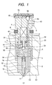
Fig. 1 is a longitudinal sectional view which shows an internal structure of a fuel injector according to the first embodiment of the invention; -
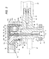
Fig. 2 is a partially enlarged sectional view ofFig. 1 ; and -
Fig. 3 is a partially longitudinal sectional view which shows an internal structure of a fuel injector according to the second embodiment of the invention. - Referring to the drawings, wherein like reference numbers refer to like parts in several views, particularly to
Figs. 1 and2 , there is shown a fuel injector according to the first embodiment of the invention which will be referred to herein as being used in, for example, automotive common rail fuel injection systems for diesel engines. - The fuel injector works to inject the fuel, as stored in a common rail (not shown) at controlled high pressures, into a combustion chamber E1 in a cylinder of an internal combustion diesel engine. The fuel injector is equipped with a
nozzle 1 from which the fuel is sprayed, apiezoelectric actuator 2 which serves as an open/close mechanism and expands when electrically charged and contracts when discharged, and a back-pressure control mechanism 3 which is operated by thepiezoelectric actuator 2 to control the back pressure acting on thenozzle 1. - The
nozzle 1 is made up of anozzle body 12 in which a spray hole(s) 11 is formed, aneedle 13 which is moved into or out of abutment with an inner seat of thenozzle body 12 to close or open thespray hole 11, and aspring 14 urging theneedle 13 in a valve-closing direction to close thespray hole 11. - The
piezoelectric actuator 2 includes a piezo stack made up of a plurality of piezoelectric devices. Thepiezoelectric actuator 2 is a capacitive load which expands when electrically charged and contracts when discharged and functions as an actuator to move theneedle 13. - The back-
pressure control mechanism 3 includes avalve body 31 within which apiston 32, a disc spring 33, and aball valve 34 are disposed. Thepiston 32 is moved following the stroke of thepiezoelectric actuator 2. The disc spring 33 urges thepiston 32 into constant abutment with thepiezoelectric actuator 2. Theball valve 34 is moved by thepiston 32. Thevalve body 31 is illustrated as being made by a one-piece member, but is actually formed by a plurality of blocks. - The fuel injector also includes a
cylindrical injector body 4 in which acylindrical mount chamber 41 is formed which extends along a longitudinal center line of the fuel injector. Themount chamber 41 has an inner shoulder to define a small-diameter housing (i.e., an upper housing, as viewed inFig. 1 ) in which thepiezoelectric actuator 2 is mounted and a large-diameter housing (i.e., a lower housing, as viewed inFig. 1 ) in which the back-pressure control mechanism 3 is mounted. A hollowcylindrical retainer 5 is fit in theinjector body 4 in a screw fashion to retain thenozzle 1 within the head of theinjector body 4. - The
nozzle body 12, theinjector body 4, and thevalve body 31 have formed therein a high-pressure path 6 through which the fuel is delivered at a controlled high pressure from the common rail to thespray hole 11. Theinjector body 4 and thevalve body 31 have also formed therein a low-pressure path 7 which connects with a fuel tank (not shown). Thenozzle body 12, theinjector body 4, and thevalve body 31 are made of metallic material and to be fit in a mount hole E3 formed in a cylinder head E2 of the engine. Theinjector body 4 has anouter shoulder 42 with which an end of a clamp K is to engage for securing the fuel injector in the mount hole E3 tightly Specifically, installation of the fuel injector in the mount hole E3 is achieved by fastening the other end of the clamp K to the cylinder head E2 through a bolt to press theouter shoulder 42 into the mount hole E3. - Between the outer periphery of a top portion of the
needle 13 close to thespray hole 11 and the inner periphery of thenozzle body 12, a high-pressure chamber 15 is formed which establishes a fluid communication between the high-pressure path 6 and thespray hole 11 when theneedle 13 is lifted up in a valve-opening direction. The high-pressure chamber 15 is supplied with the high-pressure fuel through the high-pressure path 6 at all times. A back-pressure chamber 16 is formed by one of ends of theneedle 13 which is opposite thespray hole 11. Thespring 14 is disposed within the back-pressure chamber 16 to urge theneedle 13 in the valve-closing direction. - The
valve body 31 has formed therein a high-pressure seat 35 exposed to a fluid path extending between the high-pressure path 6 and the back-pressure chamber 16. Thevalve body 31 has also formed therein a low-pressure seat 36 exposed to a path extending between the low-pressure path 7 and the back-pressure chamber 16 in thenozzle 1. The low-pressure seat 36 faces the high-pressure seat 35 to define a valve chamber within which theball valve 34 is disposed. - The
injector body 4 has, as shown inFigs. 1 and2 , a high-pressure port (i.e., a fuel inlet) 43 to which a high-pressure pipe HP is to be connected and a low-pressure port (i.e., a fuel outlet) 44 to which a low-pressure pipe LP (i.e., a drain pipe) is to be connected. The low-pressure port 44 may be located either below or above the clamp K, in other words, closer to or farther from thespray hole 11 than the claim K, as illustrated inFig. 1 or2 . Similarly, the high-pressure port 43 may be located wither below or above the clamp K. - The fuel injector of this embodiment is so designed that the fuel is delivered from the common rail to the high-
pressure port 43 through the high-pressure pipe HP, in other words, the fuel enters thecylindrical injector body 4 at an outer circumferential wall thereof. The fuel, as having entered the fuel injector, passes throughportions pressure path 6 within the high-pressure port 43, as clearly illustrated inFig. 2 , which extend perpendicular to the axis (i.e., the longitudinal direction) of the fuel injector, flows through aportion 6c of the high-pressure path 6 extending parallel to the axis of the fuel injector, and then enters the high-pressure chamber 15 and the back-pressure chamber 16. - The high-
pressure paths pressure path 6 intersect with each other at substantially right angles to in the form of an elbow. The high-pressure path 6 also includes abranch path 6e which extends from a joint orintersection 6d between the high-pressure paths spray hole 11 in parallel to the longitudinal axis of theinjector body 4. Thebranch path 6c leads to afuel pressure sensor 50, as will be described below in detail. - The high-
pressure path 6a is greater in diameter than the high-pressure path 6b within the high-pressure port 43. Afilter 45 is, as can be seen inFig. 2 , disposed inside the high-pressure path 6a to trap foreign matters contained in the fuel supplied from the common rail. - When the
piezoelectric actuator 2 is in a contracted state, thevalve 34 is, as illustrated inFig. 1 , urged into abutment with the low-pressure seat 36 to establish the fluid communication between the back-pressure chamber 16 and the high-pressure path 6, so that the high-pressure fuel is supplied to the back-pressure chamber 16. The pressure of the fuel in the back-pressure chamber 16 and the elastic pressure, as produced by thespring 14 act on theneedle 13 to urge it in the valve-closing direction to close thespray hole 11. - Alternatively, when the
piezoelectric actuator 2 is in an expanded state, thevalve 34 is pushed into abutment with the high-pressure seat 35 to establish the fluid communication between the back-pressure chamber 16 and the low-pressure path 7, so that the pressure in the back-pressure chamber 16 drops, thereby causing theneedle 13 to be urged by the pressure of fuel in the high-pressure chamber 15 in the valve-opening direction to open thespray hole 11 to spray the fuel into the combustion chamber E1 of the engine. - The spraying of the fuel from the
spray hole 11 will result in a variation in pressure of the fuel in the high-pressure path 6. Thefuel pressure sensor 50 installed in theinjector body 4 works to measure such a fuel pressure variation. An ECU (electronic control unit) of a fuel injection system (not shown) analyses the waveform of the output from thefuel pressure sensor 50 and finds the time when the pressure of the fuel began to drop due to the spraying of the fuel from thespray hole 11 to determine the injection timing of the fuel injector. The ECU also analyzes the waveform of the output and finds the time when the pressure of the fuel began to rise due to the termination of the spraying of the fuel from thespray hole 11 to calculate the end of the injection duration for which the fuel injector is kept opened. The ECU further calculates the amount of drop in pressure of the fuel to determine the quantity of fuel actually sprayed from the fuel injector. - The structure of the
fuel pressure sensor 50 and the installation thereof in theinjector body 4 will be described below. - The
fuel pressure sensor 50 is equipped with astem 51 working as a pressure deformable member which is sensitive to the pressure of fuel in thebranch path 6e to deform elastically and astrain gauge 52 working to convert the elastic deformation or distortion of thestem 51 into an electric signal. Thestem 51 is made of metal which needs to have the mechanical strength great enough to withstand the pressure of the fuel in thebranch path 6e and a coefficient of thermal expansion low enough to keep adverse effects on the operation of thestrain gauge 52 within an allowable range. For example, thestem 51 is preferably formed by machining (cutting) or cold-forging a material made of a mixture of main components of Fe, Ni, and Co or Fe and Ni and additives of Ti, Nb, and Al or Ti and Nb as precipitation strengthening materials. - The
stem 51 includes a hollowcylindrical body 51b, as illustrated inFig. 2 , and a circular plate-madediaphragm 51c. Thecylindrical body 51b has formed in an end thereof afuel inlet 51a into which the fuel enters. Thediaphragm 51c closes the other end of thecylindrical body 51b. The pressure of the fuel entering thecylindrical body 51b at theinlet 51a is exerted on thediaphragm 51c and aninner wall 51d of thecylindrical body 51b, so that thestem 51 is deformed elastically as a whole. - The
cylindrical body 51b and thediaphragm 51c are axial-symmetrical with respect to a longitudinal center line J1 (i.e., an axis), as indicated by a dashed-dotted line inFig. 2 , of the fuel pressure sensor 50 (i.e., the stem 51), so that thestem 51 will deform axisymmetrically when subjected to the pressure of the fuel. The longitudinal center line J1 of thestem 51 is offset from the longitudinal center line J2 of theinjector body 4 in parallel thereto. In other words, thefuel pressure sensor 50 is placed in misalignment with theinjector body 4 in the longitudinal direction of the fuel injector. - The
injector body 4 has formed in the end (i.e., an upper end, as viewed infig. 2 ) thereof a recess or mountchamber 46 in which thecylindrical body 51b of thestem 51 is mounted. Themount chamber 46 has an internal thread formed on an inner peripheral wall thereof. Thecylindrical body 51b has anexternal thread 51e formed on an outer peripheral wall thereof. The installation of thestem 51 in theinjector body 4 is achieved by inserting thestem 51 into themount chamber 46 from outside theinjector body 4 along the longitudinal center line J2 and fastening achamfered surface 51f formed on the outer periphery of thecylindrical body 51b using a tool such as a spanner to engage theexternal thread 51e of thecylindrical body 51b with the internal thread of themount chamber 46. - The bottom of the
mount chamber 46 of theinjector body 4 has anannular sealing surface 46a extending around the circumference of the open end of theinlet 51a. Similarly, thecylindrical body 51b of thestem 51 has formed on the top end (i.e., the lower end, as viewed inFig. 2 ) thereof facing thespray hole 11 anannular sealing surface 51g which is to be placed in close abutment with the sealingsurface 46a when thefuel pressure sensor 50 is fastened in themount chamber 46 tightly. Specifically, the tight engagement of theeternal thread 51e of thecylindrical body 51b with the internal thread of themount chamber 46 urges the sealingsurface 51g of thecylindrical body 51b into constant abutment with the sealingsurface 46a of themount chamber 46 to create a hermetical metal-touch-seal between theinjector body 4 and thestem 51. This avoids the leakage of the fuel from thebranch path 6e to outside theinjector body 4 through a contact between theinjector body 4 and thestem 51. Each of the sealing surfaces 46a and 51g extends perpendicular to the longitudinal center line J1 of thestem 51. - The
strain gauge 52 is affixed to amount surface 51h of thediaphragm 51c through an insulating film (not shown). Themount surface 51h is one of opposed outer major surfaces of thediaphragm 51c which is far from theinlet 51a. When the pressure of the fuel enters thecylindrical body 51b, so that thestem 51 elastically expands, thediaphragm 51c will deform. This causes thestrain gauge 52 to produce an electrical output as a function of the amount of deformation of thediaphragm 51c. Thediaphragm 51c and a portion of thecylindrical body 51b are located outside themount chamber 46. Thediaphragm 51c is disposed on thecylindrical body 51b so as to extend perpendicular to the longitudinal center line J1 of thestem 51. - An insulating
substrate 53 is placed flush with themount surface 51h. On the insulatingsubstrate 53,circuit component parts 54 are fabricated which constitute a voltage applying circuit and an amplifier which are electrically connected to thestrain gauge 52 through wires W using wire bonding techniques. Thestrain gauge 52 forms a bridge circuit along with resistors (not shown). The voltage applying circuit works to apply the voltage to thestrain gauge 52. This causes the bridge circuit to change a resistance value thereof as a function of the degree of deformation of thediaphragm 51c, thus resulting in a change in output voltage from the bridge circuit. Specifically, the bridge circuit produces the voltage as indicating the pressure of the fuel in thebranch path 6e. The amplifier works to amplify the output from the strain gauge 52 (i.e., the voltage produced by the bridge circuit) and outputs it from one of four sensor terminals 55: one being a sensor output terminal, one being a voltage terminal, one being a circuit control terminal, and one being a ground terminal. Driveterminals 56 extend parallel to the sensor terminal s55 in connection with positive and negative power supply leads 21 extending from thepiezoelectric actuator 2. Thedrive terminals 56 serve to supply electric power (e.g., 160 to 170V) to thepiezoelectric actuator 2 to charge it. - The
sensor terminals 55 and thedrive terminals 56 are united by amold 60 made of resin (i.e., heat insulator material). Theresin mold 60 is made up of abody 61, aboss 62, and a hollowcylindrical wall 63. Thebody 61 is placed on one of the ends of thecylindrical injector body 4 which is far from thespray hole 11. Theboss 62 extends or projects downwardly, as viewed inFig. 2 , from thebody 61 toward thespray hole 11. Thecylindrical wall 62 extends from thebody 61 toward thespray hole 11 around theboss 62. - The
body 61 has formed therein ahole 61a within which thefuel pressure sensor 50 is disposed. Themount surface 51h of thediaphragm 51c on which thestrain gauge 52 is secured is exposed to an open end of thehole 61a far from thespray hole 11. The insulatingsubstrate 53 is affixed to one of opposed surfaces of thebody 61 which is far from thespray hole 11, so that themount surface 51h of thediaphragm 51c lies in the same plane as the insulatingsubstrate 53. Thestrain gauge 52 on themount surface 51h, thecircuit component parts 54, and the insulatingsubstrate 53 are disposed within amount recess 61b formed in the surface of thebody 61. Themount recess 61b is closed by aresinous cover 64. - The
boss 62 of theresin mold 60 is fitted in alead wire hole 47 which is formed in theinjector body 4 and through which the power supply leads 21 pass, thereby positioning theresin mold 60 radially of theinjector body 4. Theboss 62 has formed therein a throughhole 62a which extends substantially parallel to the longitudinal center line J2. Ends of thelead wires 21 and ends 56a of thedrive terminals 56 are exposed outside the surface of thebody 61 which is far from thespray hole 11. Each of thelead wires 21 is welded electrically to one of theends 56a of thedrive terminals 56. - The hollow
cylindrical wall 63 extends along the outer periphery of theinjector body 4. Specifically, thecylindrical wall 63 is fit on the circumference of theinjector body 4. An O-ring S1 is fit in an annular groove formed in the circumference of theinjector body 4 to establish a hermetical seal between theinjector body 4 and thecylindrical wall 63, which avoids the intrusion of water from outside theinjector body 4 to thestrain gauge 52 and thelead wires 21 through a contact between theinjector body 4 and theresin mold 60. When adhered to thelead wires 21, drops of water may flow along thelead wires 21 to wet thedrive terminals 56 and thecircuit component parts 54 undesirably. - The
sensor terminals 55 and thedrive terminals 56 disposed within theresin mold 60 are retained firmly inside aresinous connector housing 70. Specifically, thesensor terminals 55, thedrive terminals 56, and theconnector housing 70 constitute a sensor electric connector assembly. Theconnector housing 70 includes a hollowcylindrical extension 71 for establishing a mechanical connection with external lead wires (not shown), ahollow body 72 in which theresin mold 60 is retained, and a hollowcylindrical wall 73 which extends toward thespray hole 11 and is fit on thecylindrical wall 63 of theresin mold 60. - The
body 72 and thecylindrical wall 73 are contoured as a whole to conform with the contours of thebody 61, thecover 64, and thecylindrical wall 63 of theresin mold 60. Theconnector housing 70 and theresin mold 60 are assembled together using molding techniques. Specifically, thebody 72 hasannular ridges 72a which create hermetical seals between theconnector housing 70 and theresin mold 60 when theconnector housing 70 is molded so as to cover theresin mold 60, as will be described later in detail. The hermetical seals avoid the intrusion of water from outside theinjector body 4 into theconnector housing 70 through a contact between the inner wall of thecylindrical wall 73 of theconnector housing 70 and the outer wall of thecylindrical wall 73 of theresin mold 60 to wet thesensor terminals 55 and thedrive terminals 56 exposed inside thecylindrical extension 71 undesirably. - The
cylindrical wall 73 of theconnector housing 70 has anannular claw 72b which establishes a snap fit on ashoulder 48 formed on theinjector body 4, thereby securing the orientation of an assembly of theconnector housing 70 and theresin mold 60 to the longitudinal center line J1 of thestem 50. - A sequence of steps of installing the
fuel pressure sensor 50 and theconnector housing 70 in and on theinjector body 4 will be described below. - First, the
piezoelectric actuator 2 and thefuel pressure sensor 50 are installed in themount chambers injector body 4, respectively. The installation of thefuel pressure sensor 50 is, as already described above, achieved by inserting thefuel pressure sensor 50 into themount chamber 46 parallel to the longitudinal center line J2 of theinjector body 4, and turning the chamferedsurface 51f using the clamp K to press the sealingsurface 51g of thestem 51 against the sealingsurface 46a of themount chamber 46 of theinjector body 4 to establish the metal-touch-seal between theinjector body 4 and thestem 51. Thesensor terminals 55 and thedrive terminals 56 which are united by theresin mold 60 is prepared. The insulatingsubstrate 53 on which thecircuit component parts 54 are fabricated is mounted on theresin mold 60. - Next, the
resin mold 60 in and on which thesensor output terminal 55, thedrive terminals 56, and the insulatingsubstrate 53 are mounted is fitted in theinjector body 4 in which thepiezoelectric actuator 2 and thefuel pressure sensor 50 are already installed. Specifically, theboss 60 of theresin mold 60 is fitted into thelead wire hole 47. Simultaneously, thelead wires 21 are inserted into the throughhole 62a, and thefuel pressure sensor 50 is fitted into thehole 61a of thebody 61 of theresin mold 60, so that themount surface 51h of thediaphragm 51c lies flush with the insulatingsubstrate 53. - Subsequently, the
strain gauge 52 placed on themount surface 51h is joined electrically to lands on the insulatingsubstrate 53 through the wires W using the wire bonding techniques. Each of theends 21a of thelead wires 21 exposed inside themount recess 61b is welded to one of theends 56a of thedrive terminals 56. - The
cover 54 is welded or glued to theresin mold 60 to cover themount recess 61b hermetically. Finally, theconnector housing 70 is formed by resin as to cover theresin mold 60. Specifically, resin is thermally melted over theresin mold 60 to mold theconnector housing 70 so that theannular claw 72b is fit on theshoulder 48 of theinjector body 48. During such a molding process, theannular ridges 72a formed on theresin mold 60 melt to create the hermetical seals between theconnector housing 70 and theresin mold 60. This completes the installation of thefuel pressure sensor 50 and theconnector housing 70 in and on theinjector body 4. - In the complete assembly of the fuel injector, the
resin mold 60 is located between theinjector body 4 and thecircuit component parts 54 and also between thestem 51 and thecircuit component parts 54. In use, the fuel injector is disposed in the mount hole E3 of the cylinder head E2 of the engine, so that it is exposed to a high-temperature of, for example, 140°C, which leads to a concern about the thermal breakage of thecircuit component parts 54. - In order to avoid the above problem, the fuel injector of this embodiment is designed to have the
resin mold 60 serving as a thermal shield to shield thecircuit component parts 54 and the insulatingsubstrate 53 thermally from themetallic injector body 4 and themetallic stem 51, thereby protecting thecircuit component parts 54 from the heat transmitted from the combustion chamber E1 of the engine. - The structure of the fuel injector of this embodiment offers the following advantages.
- 1) The
resin mold 60 functioning as a heat insulator or thermal shield is fit on theinjector body 4 to minimize the transfer of thermal energy from the engine to the insulating substrate 53 (i.e., the circuit component parts 54) through theinjector body 4 and thestem 51 of thefuel pressure sensor 50, thereby ensuring the accuracy in measuring a change in pressure of the fuel in the fuel supply system (including the fuel injector) which will arise from the spraying of the fuel from the fuel injector into the engine. This enables the ECU (not shown) to calculate the quantity of the fuel actually sprayed from the fuel injector, the injection timing, and the injection termination time. - 2) The
fuel pressure sensor 50 is made up of thestain gauge 52 and thestem 51. Thestem 51 is fit in theinjector body 4. Thestrain gauge 52 is affixed to thestem 51. Thestem 51 is made independently from theinjector body 4, thus permitting a loss of propagation of inner stress in theinjector body 4 resulting from thermal expansion/ contraction to thestem 51 to be increased. Specifically, thestem 51 is made to be separate from theinjector body 4, thus reducing the adverse effects of the distortion of theinjector body 4 on thestem 51 on which thestrain gauge 52 is disposed as compared with when thestrain gauge 52 is attached directly to theinjector body 4. This results in improved accuracy in measuring a change in pressure of the fuel arising from the spraying of the fuel into the engine. - 3) The
stem 51 is made to be separate from theinjector body 4, thus permitting it to be made of material at low costs whose coefficient of thermal expansion is small. This results in a decrease in thermal distortion of thestem 51 to ensure the accuracy of output from thestain gauge 52. - 4) The
stem 51 is axisymmetrical in configuration thereof, thus resulting in axisymmetrical deformation thereof when thediaphragm 51c is subjected to the pressure of the fuel, thus causing thediaphragm 51c to deform elastically as a function of the pressure of the fuel exerted thereon accurately. This ensures the accuracy in determining the pressure of the fuel. - 5) The
diaphragm 51c is located outside themount recess 46 of theinjector body 4, so that it will be insensitive to the thermal distortion of theinjector body 4. This results in improved sensitivity of thediaphragm 51c to the pressure of the fuel supplied to the fuel injector. - 6) The
mount surface 51h on which thestrain gauge 52 is mounted is placed flush with the insulatingsubstrate 53 on which thecircuit component parts 54 are fabricated, thus facilitating ease of bonding thestrain gauge 52 electrically to thecircuit component parts 54 through the wires W. - 7) The installation of the
stem 51 in theinjector body 4 is achieved by screwing thestem 51 to establish the engagement of theexternal thread 51e of thestem 51 with the internal thread of theinjector body 4 to urge the sealingsurface 51g into constant abutment with the sealingsurface 46a of theinjector body 4, thereby creating the metal-touch-seal between thestem 51 and theinjector body 4 to avoid the intrusion of the fuel thereinto. - 8) The high-
pressure path 6 in theinjector body 4 has thebranch path 6e which diverges from the inlet (i.e., the high-pressure paths injector body 4, so that the fuel hardly flows or moves within thebranch path 6e as compared with within the high-pressure paths fuel pressure sensor 50 without been affected by the flow of the fuel entering the fuel injector. - 9) The
branch path 6e diverges from the high-pressure path 6, thus causing great stress to concentrate around the intersection between thepaths injector body 4 will result in an increase in stress concentrating within theinjector body 4. In order to alleviate such a drawback, thebranch path 6e is formed to extend in alignment with the high-pressure path 6c diverging from the inlet of the fuel injector (i.e., the high-pressure path 6b) to minimize the intersections in theinjector body 4. - 10) The
injector body 4 undergoes the mechanical pressure, as produced by or transmitted from the clamp K, the high- and low-pressure pipes HP and LP. Specifically, the mechanical pressure is exerted by the clamp K on theshoulder 42 of theinjector body 4 to push it into the mount hole E3 of the cylinder head E2. If the high-pressure pipe HP is joined to the high-pressure port 43 in misalignment therewith, it will cause the mechanical pressure, as produced to bring the high-pressure pipe HP into alignment with the high-pressure port 43, to be exerted on the high-pressure port 43. The same is true for the low-pressure pipe LP. The exertion of such pressure on theinjector body 4 will cause the internal stress to increase between a portion of theinjector body 4 retained in the cylinder head E2 and theshoulder 42, the high-pressure port 43, or the low-pressure port 44 on which the pressure acts directly, which is, in turn, exerted on thefuel pressure sensor 50 undesirably. In order to alleviate this problem, thefuel pressure sensor 50 is mounted at a location opposite the cylinder head E2 across theshoulder 42, the high-pressure port 43, and the low-pressure port 44. In other words, thefuel pressure sensor 50 is away from where the internal stress increases (i.e., between the portion of theinjector body 4 retained within the cylinder head E2 and theshoulder 42, the high-pressure port 43, or the low-pressure port 44), thereby minimizing the adverse effects of the internal stress on thefuel pressure sensor 50. -
Fig. 3 illustrates a fuel injector according to the second embodiment of the invention. The same reference numbers as used in the first embodiment will refer to the same parts, and explanation thereof in detail will be omitted here. - The fuel injector of the first embodiment is so designed that the installation of the
fuel pressure sensor 50 is achieved by fitting it into theinjector body 4 along the longitudinal center line J2 of theinjector body 4. The fuel injector of the second embodiment is so designed that thefuel pressure sensor 50 is inserted into theinjector body 4 from a radius direction of theinjector body 4. - Specifically, the
injector body 4 has formed in an outer circumferential wall amount chamber 461 into which thecylindrical body 51b of thestem 51 of thefuel pressure sensor 50 is to be fitted. Theinjector body 4 has formed on the inner wall of themount chamber 461 asealing surface 461a which extends parallel to the longitudinal center line J2 of theinjector body 4 and creates a hermetical metal-touch-seal between itself and the outer wall of thestem 51. - The fuel injector is also designed to have a high-
pressure port 431 to which the high-pressure pipe HP is, unlike in the first embodiment, to be joined in the longitudinal center line J2. Specifically, thecylindrical injector body 4 has the high-pressure port 431 extending away from thespray hole 11 in the axial direction of theinjector body 4. - The
branch path 6e is, as clearly illustrated inFig. 3 , formed so as to diverge from the large-diameter path 6a which is located upstream of the small-diameter path 6b and within which thefilter 45 is disposed. Specifically, thebranch path 6e extends from the large-diameter path 6a substantially perpendicular thereto so that thediaphragm 51c of thefuel pressure sensor 50 is exposed to the pressure of fuel entering the fuel injector. The large-diameter path 6a functions as an accumulator to reduce the pulsation of the pressure of fuel, as having entered therein, thereby ensuring the accuracy in measuring a change in pressure of the fuel arising from the spraying thereof from the fuel injector. - In order to decrease the number of intersections between fuel flow paths in the
injector body 4 which will result in an increase in stress concentrating within theinjector body 4 in terms of the mechanical strength of theinjector body 4, thebranch path 6e may alternatively be formed to connect directly with the small-diameter path 6b. - While the present invention has been disclosed in terms of the preferred embodiments in order to facilitate better understanding thereof, it should be appreciated that the invention can be embodied in various ways without departing from the principle of the invention. Therefore, the invention should be understood to include all possible embodiments and modifications to the shown embodiments witch can be embodied without departing from the principle of the invention as set forth in the appended claims.
- The fuel injector may be designed to have a combination of the features as discussed above.
- The
resin mode 60 may alternatively be made of rubber, ceramic material, or resin foam in order to improve the thermal resistance thereof. - The
sensor terminals 55 may alternatively be disposed only in a resin mold which is separate from theresin mold 60. These two resin molds are preferably fit within theconnector housing 70 in order to minimize the number of electric connectors used in the fuel injector. - The
sensor output terminal 55 and thedrive terminals 56 may alternatively be disposed in a holder separate from theresin mold 60. - The
strain gauge 52 may alternatively be affixed directly to a portion of theinjector body 4 to which the pressure of fuel supplied to the fuel injector is exposed. For instance, the portion of theinjector body 4 is machined to have a thin wall so as to function as a diaphragm. Thestrain gauge 52 is affixed to the thin wall. The surface of the thin wall to which thestrain gauge 52 is to be affixed is preferably formed flush with the insulatingsubstrate 53 on which thecircuit component parts 54 are fabricated in order to improve the efficiency of work to joining thestrain gauge 52 to thecircuit component parts 54. - The
resin mold 60 may alternatively be disposed outside theconnector housing 70. For instance, theconnector housing 70 may be formed so as to partially cover or not to cover theresin mold 60. - The
fuel pressure sensor 50 may alternatively be equipped with a piezoelectric device or another type of pressure sensitive device instead of thestrain gauge 52. - The insulating
substrate 53 and thestrain gauge 52 may alternatively be arrayed to overlap each other along the longitudinal center line J1. - The
fuel pressure sensor 50 may alternatively be installed in a portion of theinjector body 4 which is retained inside the mount hole E3 of the cylinder head E2. Thefuel pressure sensor 50 may also be installed in a portion of theinjector body 4 which is closer to thespray hole 11 than the clamp K. - The invention may be used with fuel injectors designed to inject the fuel into direct injection gasoline engines as well as those for diesel engines.
- A fuel injector for an internal combustion engine is provided. The fuel injector is equipped with a fuel pressure sensor which is installed in a metallic injector body. The fuel injector also includes an amplifier working to amplify an output of the fuel pressure sensor and a thermal insulating member disposed between the metallic injector body and the amplifier to shield the amplifier thermally, thereby ensuring the accuracy in measuring the pressure of fuel within the fuel injector.
Claims (5)
- A fuel injector for an internal combustion engine comprising:a metallic body in which a fuel flow path is formed which extends from a fuel inlet to a spray hole;an actuator disposed within said metallic body, said actuator working to open the spray hole to spray fuel, as supplied to the fuel flow path through the fuel inlet, to an internal combustion engine;a fuel pressure sensor installed in said metallic body, said fuel pressure sensor working to measure a pressure of the fuel in the fuel flow path and produce an electric signal indicative thereof;a circuit component serving as an amplifier to amplify the electric signal, as produced by said fuel pressure sensor to output the electric signal; anda thermal insulating member disposed between the said metallic body and the circuit component to shield said circuit component thermally.
- A fuel injector as set forth in claim 1, wherein said fuel pressure sensor includes a metallic deformable member and a sensing device, the metallic deformable member being secured to said metallic body to deform elastically when subjected to the pressure of the fuel, the sensing device being mounted on the metallic deformable member to produce the electric signal as a function of an amount of deformation of the metallic deformable member, and wherein said thermal insulating member is disposed between the deformable member and the circuit component.
- A fuel injector as set forth in claim 2, wherein said thermal insulating member has formed therein a through hole extending from one of opposed surfaces thereof which faces said metallic body to the other of the opposed surfaces on which the circuit component is mounted, wherein said metallic deformable member is disposed inside the through hole, wherein the circuit component is fabricated on an insulating substrate, and wherein the thermal insulating member has formed on the other of the opposed surfaces a mount area on which the sensing device of said fuel pressure sensor is mounted and which lies flush with the insulating substrate.
- A fuel injector as set forth in claim 1, wherein said thermal insulating member has the circuit component mounted thereon and also has retained therein connector terminals leading electrically to the circuit component, and wherein said thermal insulating member, the connector terminals, and the circuit component are united as an assembly.
- A fuel injector as set forth in claim 1, wherein said thermal insulating member is made of one of resin, rubber, and ceramic.
Applications Claiming Priority (1)
| Application Number | Priority Date | Filing Date | Title |
|---|---|---|---|
| JP2007289074A JP4959509B2 (en) | 2007-11-06 | 2007-11-06 | Fuel injection valve |
Publications (2)
| Publication Number | Publication Date |
|---|---|
| EP2058511A1 true EP2058511A1 (en) | 2009-05-13 |
| EP2058511B1 EP2058511B1 (en) | 2011-02-16 |
Family
ID=40418976
Family Applications (1)
| Application Number | Title | Priority Date | Filing Date |
|---|---|---|---|
| EP08168397A Not-in-force EP2058511B1 (en) | 2007-11-06 | 2008-11-05 | Fuel injector with fuel pressure sensor |
Country Status (5)
| Country | Link |
|---|---|
| US (1) | US8402949B2 (en) |
| EP (1) | EP2058511B1 (en) |
| JP (1) | JP4959509B2 (en) |
| CN (1) | CN101429912B (en) |
| DE (1) | DE602008004965D1 (en) |
Cited By (1)
| Publication number | Priority date | Publication date | Assignee | Title |
|---|---|---|---|---|
| DE102010016231B4 (en) | 2009-04-03 | 2021-08-26 | Denso Corporation | Fuel injection device |
Families Citing this family (19)
| Publication number | Priority date | Publication date | Assignee | Title |
|---|---|---|---|---|
| JP5079650B2 (en) * | 2007-11-02 | 2012-11-21 | 株式会社デンソー | Fuel injection valve and fuel injection device |
| JP5064341B2 (en) * | 2007-11-02 | 2012-10-31 | 株式会社デンソー | Fuel injection valve and fuel injection device |
| JP5383132B2 (en) * | 2008-03-28 | 2014-01-08 | 株式会社デンソー | Fuel pressure sensor mounting structure, fuel pressure detection system, fuel injection device, pressure detection device and pressure accumulation fuel injection device system used therefor |
| JP5195451B2 (en) * | 2008-04-15 | 2013-05-08 | 株式会社デンソー | FUEL INJECTION DEVICE AND PRESSURE ACCUMULATION FUEL INJECTION SYSTEM USED FOR THE SAME |
| JP5154495B2 (en) * | 2009-04-03 | 2013-02-27 | 株式会社日本自動車部品総合研究所 | Fuel injection valve and internal electric connection method of fuel injection valve |
| JP5169950B2 (en) * | 2009-04-03 | 2013-03-27 | 株式会社デンソー | Fuel injection valve |
| JP5169951B2 (en) * | 2009-04-03 | 2013-03-27 | 株式会社デンソー | Fuel injection valve |
| JP5265439B2 (en) * | 2009-04-03 | 2013-08-14 | 株式会社デンソー | Fuel injection valve |
| JP2011047280A (en) * | 2009-08-25 | 2011-03-10 | Denso Corp | Fuel injection valve |
| CN102235932B (en) * | 2010-04-28 | 2012-12-05 | 雷彼得 | Internal combustion engine cylinder pressure sensor with metal ceramic electric heating body |
| JP2012215153A (en) * | 2011-04-01 | 2012-11-08 | Denso Corp | Electronic component device |
| JP5447491B2 (en) * | 2011-11-23 | 2014-03-19 | 株式会社デンソー | Fuel pressure sensor abnormality diagnosis device |
| JP6175059B2 (en) * | 2012-06-08 | 2017-08-02 | 本田技研工業株式会社 | Fuel injection device |
| US9429120B2 (en) * | 2012-10-29 | 2016-08-30 | Woodward, Inc. | Detecting leaks in a feedthrough device |
| US9590164B2 (en) | 2013-05-03 | 2017-03-07 | Parker-Hannifin Corporation | Encapsulated piezoelectric valve |
| JP6348573B2 (en) * | 2014-03-27 | 2018-06-27 | シチズンファインデバイス株式会社 | Pressure detection device |
| US20190362115A1 (en) * | 2018-05-22 | 2019-11-28 | Hamilton Sundstrand Corporation | Calibration system based on encoded images |
| EP3587791B1 (en) * | 2018-06-21 | 2021-03-24 | Claverham Limited | Flow control nozzle |
| JP7293959B2 (en) * | 2019-08-06 | 2023-06-20 | 株式会社デンソー | fuel injector |
Citations (5)
| Publication number | Priority date | Publication date | Assignee | Title |
|---|---|---|---|---|
| EP0316257A2 (en) * | 1987-11-09 | 1989-05-17 | Stanadyne Automotive Corp. | Piezoelectric sensor |
| DE19945673A1 (en) * | 1999-09-24 | 2001-04-05 | Daimler Chrysler Ag | Injection nozzle for internal combustion engines |
| EP1321660A2 (en) * | 2001-12-18 | 2003-06-25 | Caterpillar Inc. | Measuring check motion through pressure sensing |
| DE10336816A1 (en) * | 2003-08-11 | 2005-03-10 | Bosch Gmbh Robert | Method for measuring pressure in a control chamber of a fuel injector of an internal combustion engine especially common rail injectors whereby pressure is measured indirectly via deformation of the valve piston |
| DE102005024194A1 (en) | 2005-05-25 | 2006-11-30 | Siemens Ag | Fuel injector, for an internal combustion motor, has a pressure sensor at the high pressure feed for a control zone to set the valve and jet needle positions |
Family Cites Families (31)
| Publication number | Priority date | Publication date | Assignee | Title |
|---|---|---|---|---|
| US3883715A (en) * | 1973-12-03 | 1975-05-13 | Sybron Corp | Controlled environment module |
| GB2019581B (en) * | 1978-02-08 | 1982-10-13 | Scotus Patentverwalt | Pressure sensing apparatus |
| JPS575526A (en) * | 1980-06-11 | 1982-01-12 | Diesel Kiki Co Ltd | Method of detecting injection flow in fuel injection valve |
| JPH0612101B2 (en) * | 1985-07-02 | 1994-02-16 | トヨタ自動車株式会社 | Fuel injection control device for internal combustion engine |
| US4858073A (en) * | 1986-12-10 | 1989-08-15 | Akzo America Inc. | Metal substrated printed circuit |
| US5789673A (en) * | 1993-09-14 | 1998-08-04 | Hitachi, Ltd. | Thermal type air flow measuring instrument for internal combustion engine |
| US5700526A (en) * | 1995-05-04 | 1997-12-23 | Schlumberger Technologies Inc. | Insulator deposition using focused ion beam |
| US5631417A (en) * | 1995-09-06 | 1997-05-20 | General Motors Corporation | Mass air flow sensor structure with bi-directional airflow incident on a sensing device at an angle |
| US5712422A (en) * | 1995-09-20 | 1998-01-27 | Sanshin Kogyo Kabushiki Kaisha | Engine sensor |
| US5918275A (en) * | 1996-03-26 | 1999-06-29 | Sanshin Kogyo Kabushiki Kaisha | Sensor for engine control |
| DE69733279T2 (en) * | 1997-02-06 | 2006-01-19 | Optrand, Inc., Plymouth | FUEL INJECTION UNITS WITH INTEGRATED FIBER OPTICAL PRESSURE SENSORS AND ASSOCIATED COMPENSATION AND MONITORING DEVICES |
| US6622549B1 (en) * | 1997-02-06 | 2003-09-23 | Marek T. Wlodarczyk | Fuel injectors with integral fiber optic pressure sensors and associated compensation and status monitoring devices |
| JP3695207B2 (en) | 1999-03-18 | 2005-09-14 | いすゞ自動車株式会社 | Engine fuel injector |
| JP4623776B2 (en) * | 1999-03-25 | 2011-02-02 | 株式会社デンソー | Manufacturing method of pressure sensor |
| JP4194007B2 (en) * | 1999-05-26 | 2008-12-10 | ヤマハマリン株式会社 | 2-cycle engine |
| JP4003363B2 (en) * | 1999-12-24 | 2007-11-07 | 株式会社デンソー | Combustion pressure sensor structure |
| EP1118849B1 (en) | 2000-01-18 | 2002-08-14 | Denso Corporation | High-pressure sensor with one or two threaded stems bearing multi-pad sensor chips |
| JP4407038B2 (en) * | 2000-01-18 | 2010-02-03 | 株式会社デンソー | Pressure sensor |
| EP1128168A3 (en) * | 2000-02-23 | 2002-07-03 | Hitachi, Ltd. | Measurement apparatus for measuring physical quantity such as fluid flow |
| DE10014737A1 (en) * | 2000-03-24 | 2001-10-11 | Bosch Gmbh Robert | Method for determining the rail pressure of an injection valve with a piezoelectric actuator |
| DE10127932A1 (en) * | 2001-06-08 | 2002-12-19 | Bosch Gmbh Robert | Motor vehicle combustion engine fuel injector has an integral pressure sensor in the combustion chamber that supplies pressure information to a valve member so that its behavior is controlled accordingly |
| GB2386470B (en) * | 2002-03-11 | 2004-06-16 | Toshiba Res Europ Ltd | A photon source and method of operating a photon source |
| EP1365216B1 (en) * | 2002-05-10 | 2018-01-17 | Azbil Corporation | Flow sensor and method of manufacturing the same |
| FR2870082B1 (en) * | 2004-05-07 | 2006-07-07 | Valitec Soc Par Actions Simpli | STATIC ELECTRICITY ELIMINATOR, IN PARTICULAR FOR THE TREATMENT OF POLYMERS |
| US7337768B2 (en) * | 2004-05-07 | 2008-03-04 | Philip Morris Usa Inc. | Multiple capillary fuel injector for an internal combustion engine |
| JP5204488B2 (en) * | 2004-11-03 | 2013-06-05 | フィリップ・モリス・ユーエスエイ・インコーポレイテッド | High frequency evaporative fuel injection device |
| DE102005009644B4 (en) * | 2005-03-03 | 2013-09-12 | Schott Ag | Ignition device for a pyrotechnic protection device, method for producing such an ignition device and gas generator with such an ignition device |
| TWI290012B (en) * | 2005-03-03 | 2007-11-11 | Mitac Technology Corp | Printed circuit board structure and manufacturing method thereof |
| DK1951110T3 (en) * | 2005-10-24 | 2013-01-21 | Marcio Marc Aurelio Martins Abreu | Apparatus for measuring biological parameters |
| JP4840288B2 (en) * | 2006-11-14 | 2011-12-21 | 株式会社デンソー | Fuel injection apparatus and adjustment method thereof |
| US7552717B2 (en) * | 2007-08-07 | 2009-06-30 | Delphi Technologies, Inc. | Fuel injector and method for controlling fuel injectors |
-
2007
- 2007-11-06 JP JP2007289074A patent/JP4959509B2/en not_active Expired - Fee Related
-
2008
- 2008-11-05 DE DE602008004965T patent/DE602008004965D1/en active Active
- 2008-11-05 EP EP08168397A patent/EP2058511B1/en not_active Not-in-force
- 2008-11-06 US US12/265,743 patent/US8402949B2/en not_active Expired - Fee Related
- 2008-11-06 CN CN2008101704529A patent/CN101429912B/en not_active Expired - Fee Related
Patent Citations (5)
| Publication number | Priority date | Publication date | Assignee | Title |
|---|---|---|---|---|
| EP0316257A2 (en) * | 1987-11-09 | 1989-05-17 | Stanadyne Automotive Corp. | Piezoelectric sensor |
| DE19945673A1 (en) * | 1999-09-24 | 2001-04-05 | Daimler Chrysler Ag | Injection nozzle for internal combustion engines |
| EP1321660A2 (en) * | 2001-12-18 | 2003-06-25 | Caterpillar Inc. | Measuring check motion through pressure sensing |
| DE10336816A1 (en) * | 2003-08-11 | 2005-03-10 | Bosch Gmbh Robert | Method for measuring pressure in a control chamber of a fuel injector of an internal combustion engine especially common rail injectors whereby pressure is measured indirectly via deformation of the valve piston |
| DE102005024194A1 (en) | 2005-05-25 | 2006-11-30 | Siemens Ag | Fuel injector, for an internal combustion motor, has a pressure sensor at the high pressure feed for a control zone to set the valve and jet needle positions |
Cited By (1)
| Publication number | Priority date | Publication date | Assignee | Title |
|---|---|---|---|---|
| DE102010016231B4 (en) | 2009-04-03 | 2021-08-26 | Denso Corporation | Fuel injection device |
Also Published As
| Publication number | Publication date |
|---|---|
| JP4959509B2 (en) | 2012-06-27 |
| EP2058511B1 (en) | 2011-02-16 |
| CN101429912A (en) | 2009-05-13 |
| US8402949B2 (en) | 2013-03-26 |
| DE602008004965D1 (en) | 2011-03-31 |
| JP2009114970A (en) | 2009-05-28 |
| US20090118981A1 (en) | 2009-05-07 |
| CN101429912B (en) | 2011-11-16 |
Similar Documents
| Publication | Publication Date | Title |
|---|---|---|
| EP2058511B1 (en) | Fuel injector with fuel pressure sensor | |
| EP2058508B1 (en) | Fuel injector with electric shield | |
| EP2058510B1 (en) | Internal combustion engine having a fuel injector designed to minimize mechanical stress on fuel pressure sensor installed therein | |
| EP2105607B1 (en) | Fuel injector with built-in fuel pressure sensor | |
| US8590513B2 (en) | Fuel injection valve and fuel injection device | |
| EP2105602B1 (en) | Fuel pressure sensor/sensor mount assembly | |
| EP2105605B1 (en) | Fuel pressure sensor/sensor mount assembly | |
| US20100263633A1 (en) | Fuel injection valve and fuel injection apparatus | |
| EP2110540B1 (en) | Fuel injector with fuel pressure sensor | |
| US20100313850A1 (en) | Fuel injection valve and fuel injection device | |
| US20100251999A1 (en) | Fuel injection valve | |
| US20100252002A1 (en) | Fuel injector with fuel pressure sensor and electrical interconnection method of the same | |
| US20100252651A1 (en) | Fuel injection apparatus | |
| US7913929B2 (en) | Modular outward opening piezo direct fuel injector | |
| EP1876349A1 (en) | Injector assembly for an injector |
Legal Events
| Date | Code | Title | Description |
|---|---|---|---|
| PUAI | Public reference made under article 153(3) epc to a published international application that has entered the european phase |
Free format text: ORIGINAL CODE: 0009012 |
|
| AK | Designated contracting states |
Kind code of ref document: A1 Designated state(s): AT BE BG CH CY CZ DE DK EE ES FI FR GB GR HR HU IE IS IT LI LT LU LV MC MT NL NO PL PT RO SE SI SK TR |
|
| AX | Request for extension of the european patent |
Extension state: AL BA MK RS |
|
| 17P | Request for examination filed |
Effective date: 20090819 |
|
| 17Q | First examination report despatched |
Effective date: 20090923 |
|
| AKX | Designation fees paid |
Designated state(s): DE FR GB IT |
|
| GRAP | Despatch of communication of intention to grant a patent |
Free format text: ORIGINAL CODE: EPIDOSNIGR1 |
|
| GRAS | Grant fee paid |
Free format text: ORIGINAL CODE: EPIDOSNIGR3 |
|
| GRAA | (expected) grant |
Free format text: ORIGINAL CODE: 0009210 |
|
| AK | Designated contracting states |
Kind code of ref document: B1 Designated state(s): DE FR GB IT |
|
| REG | Reference to a national code |
Ref country code: GB Ref legal event code: FG4D |
|
| REF | Corresponds to: |
Ref document number: 602008004965 Country of ref document: DE Date of ref document: 20110331 Kind code of ref document: P |
|
| REG | Reference to a national code |
Ref country code: DE Ref legal event code: R096 Ref document number: 602008004965 Country of ref document: DE Effective date: 20110331 |
|
| PLBE | No opposition filed within time limit |
Free format text: ORIGINAL CODE: 0009261 |
|
| STAA | Information on the status of an ep patent application or granted ep patent |
Free format text: STATUS: NO OPPOSITION FILED WITHIN TIME LIMIT |
|
| 26N | No opposition filed |
Effective date: 20111117 |
|
| REG | Reference to a national code |
Ref country code: DE Ref legal event code: R097 Ref document number: 602008004965 Country of ref document: DE Effective date: 20111117 |
|
| REG | Reference to a national code |
Ref country code: FR Ref legal event code: PLFP Year of fee payment: 8 |
|
| REG | Reference to a national code |
Ref country code: FR Ref legal event code: PLFP Year of fee payment: 9 |
|
| REG | Reference to a national code |
Ref country code: FR Ref legal event code: PLFP Year of fee payment: 10 |
|
| PGFP | Annual fee paid to national office [announced via postgrant information from national office to epo] |
Ref country code: IT Payment date: 20191128 Year of fee payment: 12 Ref country code: FR Payment date: 20191120 Year of fee payment: 12 |
|
| PGFP | Annual fee paid to national office [announced via postgrant information from national office to epo] |
Ref country code: GB Payment date: 20191120 Year of fee payment: 12 |
|
| GBPC | Gb: european patent ceased through non-payment of renewal fee |
Effective date: 20201105 |
|
| PG25 | Lapsed in a contracting state [announced via postgrant information from national office to epo] |
Ref country code: FR Free format text: LAPSE BECAUSE OF NON-PAYMENT OF DUE FEES Effective date: 20201130 Ref country code: IT Free format text: LAPSE BECAUSE OF NON-PAYMENT OF DUE FEES Effective date: 20201105 |
|
| PG25 | Lapsed in a contracting state [announced via postgrant information from national office to epo] |
Ref country code: GB Free format text: LAPSE BECAUSE OF NON-PAYMENT OF DUE FEES Effective date: 20201105 |
|
| PGFP | Annual fee paid to national office [announced via postgrant information from national office to epo] |
Ref country code: DE Payment date: 20231121 Year of fee payment: 16 |
|
| REG | Reference to a national code |
Ref country code: DE Ref legal event code: R119 Ref document number: 602008004965 Country of ref document: DE |
|
| PG25 | Lapsed in a contracting state [announced via postgrant information from national office to epo] |
Ref country code: DE Free format text: LAPSE BECAUSE OF NON-PAYMENT OF DUE FEES Effective date: 20250603 |