EP2058175A2 - Cargo box - Google Patents
Cargo box Download PDFInfo
- Publication number
- EP2058175A2 EP2058175A2 EP08168364A EP08168364A EP2058175A2 EP 2058175 A2 EP2058175 A2 EP 2058175A2 EP 08168364 A EP08168364 A EP 08168364A EP 08168364 A EP08168364 A EP 08168364A EP 2058175 A2 EP2058175 A2 EP 2058175A2
- Authority
- EP
- European Patent Office
- Prior art keywords
- cargo box
- floor
- utility vehicle
- side panels
- accessory
- Prior art date
- Legal status (The legal status is an assumption and is not a legal conclusion. Google has not performed a legal analysis and makes no representation as to the accuracy of the status listed.)
- Withdrawn
Links
- 239000002184 metal Substances 0.000 claims abstract description 15
- 239000002131 composite material Substances 0.000 claims abstract description 11
- 229920000642 polymer Polymers 0.000 claims abstract description 9
- 239000004743 Polypropylene Substances 0.000 claims description 4
- -1 polypropylene Polymers 0.000 claims description 4
- 229920001155 polypropylene Polymers 0.000 claims description 4
- 239000000835 fiber Substances 0.000 claims 1
- 239000000463 material Substances 0.000 description 6
- 230000003014 reinforcing effect Effects 0.000 description 6
- 229910000831 Steel Inorganic materials 0.000 description 4
- 239000010959 steel Substances 0.000 description 4
- 239000003562 lightweight material Substances 0.000 description 3
- 238000005286 illumination Methods 0.000 description 2
- 239000002991 molded plastic Substances 0.000 description 2
- 239000002861 polymer material Substances 0.000 description 2
- 229920002396 Polyurea Polymers 0.000 description 1
- 239000000853 adhesive Substances 0.000 description 1
- 230000001070 adhesive effect Effects 0.000 description 1
- 230000000712 assembly Effects 0.000 description 1
- 238000000429 assembly Methods 0.000 description 1
- 230000004888 barrier function Effects 0.000 description 1
- 238000005452 bending Methods 0.000 description 1
- 230000015572 biosynthetic process Effects 0.000 description 1
- 239000011248 coating agent Substances 0.000 description 1
- 238000000576 coating method Methods 0.000 description 1
- 239000002537 cosmetic Substances 0.000 description 1
- 238000004519 manufacturing process Methods 0.000 description 1
- 230000004048 modification Effects 0.000 description 1
- 238000012986 modification Methods 0.000 description 1
- 239000006223 plastic coating Substances 0.000 description 1
- 210000001364 upper extremity Anatomy 0.000 description 1
Images




Classifications
-
- B—PERFORMING OPERATIONS; TRANSPORTING
- B60—VEHICLES IN GENERAL
- B60R—VEHICLES, VEHICLE FITTINGS, OR VEHICLE PARTS, NOT OTHERWISE PROVIDED FOR
- B60R5/00—Compartments within vehicle body primarily intended or sufficiently spacious for trunks, suit-cases, or the like
- B60R5/04—Compartments within vehicle body primarily intended or sufficiently spacious for trunks, suit-cases, or the like arranged at rear of vehicle
-
- B—PERFORMING OPERATIONS; TRANSPORTING
- B60—VEHICLES IN GENERAL
- B60Q—ARRANGEMENT OF SIGNALLING OR LIGHTING DEVICES, THE MOUNTING OR SUPPORTING THEREOF OR CIRCUITS THEREFOR, FOR VEHICLES IN GENERAL
- B60Q1/00—Arrangement of optical signalling or lighting devices, the mounting or supporting thereof or circuits therefor
- B60Q1/26—Arrangement of optical signalling or lighting devices, the mounting or supporting thereof or circuits therefor the devices being primarily intended to indicate the vehicle, or parts thereof, or to give signals, to other traffic
- B60Q1/30—Arrangement of optical signalling or lighting devices, the mounting or supporting thereof or circuits therefor the devices being primarily intended to indicate the vehicle, or parts thereof, or to give signals, to other traffic for indicating rear of vehicle, e.g. by means of reflecting surfaces
-
- B—PERFORMING OPERATIONS; TRANSPORTING
- B60—VEHICLES IN GENERAL
- B60Q—ARRANGEMENT OF SIGNALLING OR LIGHTING DEVICES, THE MOUNTING OR SUPPORTING THEREOF OR CIRCUITS THEREFOR, FOR VEHICLES IN GENERAL
- B60Q3/00—Arrangement of lighting devices for vehicle interiors; Lighting devices specially adapted for vehicle interiors
- B60Q3/30—Arrangement of lighting devices for vehicle interiors; Lighting devices specially adapted for vehicle interiors for compartments other than passenger or driving compartments, e.g. luggage or engine compartments
-
- B—PERFORMING OPERATIONS; TRANSPORTING
- B62—LAND VEHICLES FOR TRAVELLING OTHERWISE THAN ON RAILS
- B62D—MOTOR VEHICLES; TRAILERS
- B62D29/00—Superstructures, understructures, or sub-units thereof, characterised by the material thereof
- B62D29/04—Superstructures, understructures, or sub-units thereof, characterised by the material thereof predominantly of synthetic material
- B62D29/043—Superstructures
-
- B—PERFORMING OPERATIONS; TRANSPORTING
- B62—LAND VEHICLES FOR TRAVELLING OTHERWISE THAN ON RAILS
- B62D—MOTOR VEHICLES; TRAILERS
- B62D33/00—Superstructures for load-carrying vehicles
- B62D33/02—Platforms; Open load compartments
- B62D33/023—Sideboard or tailgate structures
- B62D33/027—Sideboard or tailgate structures movable
Definitions
- This invention relates to cargo boxes for off-road utility vehicles used for agricultural, industrial or recreational purposes.
- Utility vehicle cargo boxes are typically constructed of steel panels with a supporting frame under the floor.
- Composite materials, or other light weight materials such as blow-molded plastics, are not used because they are subject to high thermal expansion that can reduce the rigidity, and integrity of the cargo box.
- a cargo box for a utility vehicle is needed that utilizes light weight materials and provides high strength and durability.
- utility vehicle cargo boxes are relatively small, making it difficult to carry long items, they lack illumination of the cargo box interior, and lack adequate and easily accessible tie down straps or clamps, both in the cargo box interior and overhead.
- a cargo box for a utility vehicle is needed that can carry large or long items, provide illumination of the cargo box interior, and provides sufficient easily accessible tie down straps and clamps for cargo to be stored conveniently.
- a cargo box for a utility vehicle may include removable light weight polymer side panels fastened to a metal floor.
- the side panels may move fore and aft relative to the floor.
- Stiffening members may hold the rear of each side panel in a stationary position at the rear of the cargo box bed.
- Attachments may be mounted to the side panels using dovetail mounting attachments or accessory bars.
- a utility vehicle cargo box may comprise a pair of composite polymer side panels attached to a metal floor with a plurality of threaded fasteners that allow relative movement of the side panels with respect to the floor; a plurality of accessory fasteners on the side panels for mounting an accessory at a plurality of different locations in the cargo box.
- a utility vehicle cargo box comprising a floor including a metal plate having slots in a rear surface thereof; a pair of composite polymer side panels fastened to the floor by a plurality of fasteners that allow relative movement of the side panels fore and aft with respect to the floor; and a stiffening member attached to each side panel and inserted into the slots; each stiffening member resisting rearward movement of the side panel.
- the utility vehicle cargo box may further comprise a composite polymer tail gate hinged to the side panels as well as a load guard, the side panels fastened to the load guard by a plurality of fasteners that allow relative movement of the side panels fore and aft with respect to the load guard and an opening may be provided in the load guard and a pass-through door hinged to the opening.
- the utility vehicle cargo box may further comprise a tail light mounting recess on each side panel; a tail light mounted in each recess; and an opening behind each tail light for light to pass through the side panel.
- the floor may include a top plate and a bottom plate.
- the utility vehicle cargo box may further comprise a plurality of lateral frame members intersecting a plurality of longitudinal frame members supporting the floor; the lateral or longitudinal frame members having slots for positioning the other frame members and/or a release lever for tilting and dumping the cargo box, the release lever being parallel to the load guard and under the cargo box, the release lever being actuated by horizontal movement and/or U-bolts attached to each side panel and having threaded ends inserted through slots in the cargo box floor.
- a utility vehicle cargo box may comprise a metal floor and load guard, each having a plurality of slots; a pair of composite polymer side panels fastened to the metal floor and load guard using threaded fasteners extending through the slots such that the side panel can move relative to the metal floor and load guard; each side panel having a rear end with a stiffening member attached thereto; and the stiffening member removably connected to the metal floor.
- the utility vehicle cargo box may further comprise a plurality of accessory mounting structures removably attached to each side panel and/or a tail light mounting recess at the end of each side panel, a tail light mounted in each recess, and an aperture behind each tail light for light to pass through.
- the floor may further comprise a top sheet metal panel having first reinforcing structures overlaying a bottom sheet metal panel having second reinforcing structures oriented perpendicular to the first reinforcing structures.
- An accessory bar may be mounted to each composite polymer side panel.
- the utility vehicle cargo box may further comprising a top cover mounted on the cargo box laterally inwardly from the accessory bars.
- At least one accessory may be mountable to the accessory bars with clamps tightenable at a plurality of positions along the accessory bars, wherein the accessory is a load divider.
- cargo box 100 for a utility vehicle may have a floor 102, left and right side panels 104, 106, load guard 108, and tailgate 110.
- the left and right side panels, and the tailgate may be molded from a light weight material such as fiber-reinforced polypropylene, blow-molded plastic or another reinforced polymer.
- the floor of the cargo box and the load guard may be sheet steel.
- each stiffening member 112, 114 may be a steel L-shaped bracket attached using a fastener 116 to the side panel adjacent the rear edge of the side panel.
- the lower leg 118, 120 of each L-shaped bracket may be slip-fit through slots 122, 124 in the rear edge 126 of the cargo box floor.
- each side panel also may be fastened to the cargo box floor by inserting threaded fasteners 128 through slots 130 in the left and right edges of the floor that allow movement of the side panels fore and aft relative to the floor.
- each side panel may be fastened to the left and right edges 194, 196 of the load guard by inserting threaded fasteners 129 through slots 132 in the left and right edge of the load guard.
- Each of the slots may be oriented fore and aft.
- Thhreaded fastener 129 may be a U-bolt that is press fit into a side panel and held firmly in place. Barrel nuts may be tightened onto the threaded ends of the threaded fasteners.
- stiffening members 112, 114 may resist rearward movement of the side panels that could result in formation of a gap between the cargo box and tail gate, and thereby prevent material leakage from the box through the gap.
- each side panel may be easily detached and removed from the cargo box. This may be done by removing the barrel nuts from the threaded fasteners and sliding the stiffening members out from the slots at the rear of the cargo box floor.
- the cargo box may be provided with release lever 134 that an operator may used to tilt and/or dump the cargo box.
- release lever 134 may be attached to wire form 136 that engages latch mechanism 138.
- Release lever 134 may extend through a channel in one of the lateral frame members 140 under the cargo box and parallel to load guard 108.
- To disengage the latch release lever 134 may be pulled horizontally, or laterally outwardly, in a direction parallel to the load guard.
- the release lever and latch may be biased to the engaged position.
- Piston assemblies such as hydraulic cylinders or pneumatic dampers 137 may be fastened to braces 139 that are attached between adjacent lateral frame members 140 under cargo box floor, to help facilitate raising, tilting and/or dumping of the cargo box.
- lateral frame members 140 intersect and pass through notches 143 in a pair of longitudinal frame members 141, to provide structural support over the full width of the cargo box floor.
- the longitudinal frame members also may be channel shaped, and have a plurality of notches to self-locate the lateral frame members and thereby simplify manufacturing of the cargo box.
- each side panel facing the interior of the cargo box may have one or more raised horizontal load volume indicating stripes or ribs 142 that may be used to measure the volume of material required to fill the cargo box to its rated load capacity, and/or one or more levels below that capacity.
- Each horizontal stripe or rib 142 also may provide stiffening characteristics.
- An outer cosmetic or appearance panel also may be attached to the exterior surface of each side panel.
- accessory bars 144, 146 may be fastened to the left and right side panels.
- Each accessory bar may be tubular metal with a plastic coating.
- the ends of each accessory bar may be inserted into recesses near the front and rear near the upper surface of each side panel.
- the upper surfaces of each side panel also may include one or more reinforcing projections 148 to help support the accessory bar.
- Various accessories may be mounted to the accessory bars by clamps that are tightened to either or both accessory bars.
- the accessories may include tool mounts, tool boxes, bed wall extensions, or working lights, for example.
- Each clamp may slide along an accessory bar or rack member, and tightened at any position along the length of the bar. For example, the clamps may be hand tightened by over-center latches or threaded tighteners.
- accessory fasteners 152 may be removably attached to each of the side panels, and may be used for mounting various accessories in the cargo box.
- Each accessory fastener 152 may slide into a tapered slot 154 on the surface of the side panel facing inside the cargo box.
- Each accessory fastener 152 may have a dovetail intefit into the slot.
- a clip 156 may be connected to each accessory fastener to releasably hold it in place in the slot.
- the threaded fasteners that secure the side panels to the cargo box floor also may be used to secure tie down straps 158 to the floor.
- the lower edge of each side panel facing the cargo box interior may have a recess 160 where each tie down strap 158 may be positioned to allow an operator easy access to the strap.
- Each strap may be below the plane of the cargo box floor and within the inwardly facing surface of the side panel, so that the material in the cargo box will not interfere with the strap.
- a tail light mounting recess 162 may be provided in the rear of each side panel.
- the tail light mounting recess may include an aperture or opening 164 behind the tail light for light to pass from each tail light 165, 166 to the interior of the cargo box, thereby illuminating the cargo box interior.
- Each tail light may be a sealed unit having a clear lens so that light can pass from the tail light through the opening into the cargo box.
- the edges of the cargo box floor may be folded to provide vertically oriented surfaces.
- the cargo box floor may have a non-skid texture applied to its surface, such as a poly urea coating.
- the floor also may have a plurality of parallel reinforcing structures oriented between the front and back of the floor, such as ribs stamped into the surface.
- the cargo box floor may include a top sheet metal plate 190 overlaying a bottom sheet metal plate 192.
- the pair of plates may be attached to each other by spot welds, tape or adhesive.
- Portions of the cargo box floor may include a gap between the top and bottom plates, and a barrier layer optionally may be provided in the gap.
- the bottom plate may have reinforcing structures perpendicular to those of the top plate, extending between the left and right edges of the bottom plate.
- a pair of corner posts or uprights 170, 172 may be fastened by welds or other means at or near the front corners of the cargo box floor.
- the uprights may be hollow steel tubes.
- overhead rack 174 may be removably attached to the cargo box.
- the overhead rack may be a structure constructed from tubular members that are welded together.
- the overhead rack may include front and rear inverted U-shaped members, front legs and rear legs, and a pair of generally horizontal bars.
- Various accessories may be mounted to the overhead rack.
- tail gate 176 may be a composite polymer material such as fiber-reinforced polypropylene.
- the tail gate may be blow molded and may have multiple stiffening members.
- the tailgate may be hinged at each side to the side panels.
- a pair of lanyards 178, 180 may be fastened to the top left and right edges of the tail gate.
- the end of each lanyard may be fastened to a slot in latch plate 182 at the rear of each side panel.
- the lanyard may be fastened to a lower positioning slot 184 in the latch plate to hold the tailgate in a dropped position, or to upper positioning slot 186 to hold the tail gate horizontal.
- load guard 188 may be a composite polymer material such as fiber-reinforced polypropylene.
- the load guard may have an opening 200 covered by pass-through door 202.
- the pass-through door may be hinged to the load guard to allow access through the opening between the cargo box interior and operator station of the vehicle. The opening increases the capacity of the cargo box to carry lengthy objects exceeding the length of the cargo box itself.
- one or more load dividers 204 may be positioned in the cargo box at desired positions, with each load divider fastened to accessory bars on the left and right side of the cargo box with clamps 205.
- the load divider may be used to separate different materials that are unsecured to the cargo box.
- top cover 206 is shown mounted on the cargo box so that the accessory bars on each side of the cargo box are accessible with the top cover in place. This placement of the top cover so that its left and right sides are laterally inward from the accessory bars allows the accessory bars to be used for tying down material or objects that may be placed on the upper surface of the top cover.
Landscapes
- Engineering & Computer Science (AREA)
- Mechanical Engineering (AREA)
- Chemical & Material Sciences (AREA)
- Combustion & Propulsion (AREA)
- Transportation (AREA)
- Architecture (AREA)
- Structural Engineering (AREA)
- Body Structure For Vehicles (AREA)
- Vehicle Step Arrangements And Article Storage (AREA)
Abstract
A cargo box (100) for a utility vehicle has a metal floor (102) and composite polymer side panels (104, 106). The side panels (104, 106) may be fastened to the floor (102) such that relative movement may occur. Stiffening members (112, 114) resist rearward movement of the side panels (104, 106) that could result in a gap between the cargo box (100) and tail gate (176).
Description
- This invention relates to cargo boxes for off-road utility vehicles used for agricultural, industrial or recreational purposes.
- Off-road utility vehicles are often equipped with cargo boxes for carrying various items including tools, supplies, or material. Utility vehicle cargo boxes are typically constructed of steel panels with a supporting frame under the floor. Composite materials, or other light weight materials such as blow-molded plastics, are not used because they are subject to high thermal expansion that can reduce the rigidity, and integrity of the cargo box. A cargo box for a utility vehicle is needed that utilizes light weight materials and provides high strength and durability.
- Additionally, utility vehicle cargo boxes are relatively small, making it difficult to carry long items, they lack illumination of the cargo box interior, and lack adequate and easily accessible tie down straps or clamps, both in the cargo box interior and overhead. A cargo box for a utility vehicle is needed that can carry large or long items, provide illumination of the cargo box interior, and provides sufficient easily accessible tie down straps and clamps for cargo to be stored conveniently.
- It is therefore the object of the present invention to comply with one or all of these needs respectively.
- This object is met according to the invention by the teaching of claim, while features developing the solution in an advantageous manner are set forth in the further claims.
- A cargo box for a utility vehicle may include removable light weight polymer side panels fastened to a metal floor. The side panels may move fore and aft relative to the floor. Stiffening members may hold the rear of each side panel in a stationary position at the rear of the cargo box bed. Attachments may be mounted to the side panels using dovetail mounting attachments or accessory bars.
- In a first embodiment of the invention a utility vehicle cargo box may comprise a pair of composite polymer side panels attached to a metal floor with a plurality of threaded fasteners that allow relative movement of the side panels with respect to the floor; a plurality of accessory fasteners on the side panels for mounting an accessory at a plurality of different locations in the cargo box.
- In a second embodiment a utility vehicle cargo box comprising a floor including a metal plate having slots in a rear surface thereof; a pair of composite polymer side panels fastened to the floor by a plurality of fasteners that allow relative movement of the side panels fore and aft with respect to the floor; and a stiffening member attached to each side panel and inserted into the slots; each stiffening member resisting rearward movement of the side panel.
- The utility vehicle cargo box may further comprise a composite polymer tail gate hinged to the side panels as well as a load guard, the side panels fastened to the load guard by a plurality of fasteners that allow relative movement of the side panels fore and aft with respect to the load guard and an opening may be provided in the load guard and a pass-through door hinged to the opening.
- The utility vehicle cargo box may further comprise a tail light mounting recess on each side panel; a tail light mounted in each recess; and an opening behind each tail light for light to pass through the side panel.
- The floor may include a top plate and a bottom plate.
- The utility vehicle cargo box may further comprise a plurality of lateral frame members intersecting a plurality of longitudinal frame members supporting the floor; the lateral or longitudinal frame members having slots for positioning the other frame members and/or a release lever for tilting and dumping the cargo box, the release lever being parallel to the load guard and under the cargo box, the release lever being actuated by horizontal movement and/or U-bolts attached to each side panel and having threaded ends inserted through slots in the cargo box floor.
- According to another embodiment of the invention a utility vehicle cargo box may comprise a metal floor and load guard, each having a plurality of slots; a pair of composite polymer side panels fastened to the metal floor and load guard using threaded fasteners extending through the slots such that the side panel can move relative to the metal floor and load guard; each side panel having a rear end with a stiffening member attached thereto; and the stiffening member removably connected to the metal floor.
- The utility vehicle cargo box may further comprise a plurality of accessory mounting structures removably attached to each side panel and/or a tail light mounting recess at the end of each side panel, a tail light mounted in each recess, and an aperture behind each tail light for light to pass through.
- The floor may further comprise a top sheet metal panel having first reinforcing structures overlaying a bottom sheet metal panel having second reinforcing structures oriented perpendicular to the first reinforcing structures.
- An accessory bar may be mounted to each composite polymer side panel.
- The utility vehicle cargo box may further comprising a top cover mounted on the cargo box laterally inwardly from the accessory bars.
- At least one accessory may be mountable to the accessory bars with clamps tightenable at a plurality of positions along the accessory bars, wherein the accessory is a load divider.
- Embodiments of the invention described below are shown in the drawings, in which
- Fig. 1
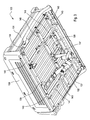
- is a rear perspective view of a first embodiment of a cargo box for a utility vehicle.
- Fig. 2
- is a front perspective view of a first embodiment of a cargo box for a utility vehicle.
- Fig. 3
- is a bottom perspective view of a first embodiment of a cargo box for a utility vehicle.
- Fig. 4
- is a view of a release latch for the cargo box of
Fig. 2 , partially in section, according to a first embodiment. - Fig. 5
- is a rear perspective view of a second embodiment of a cargo box for a utility vehicle.
- Fig. 6
- is an exploded rear perspective view of the second embodiment.
- Fig. 7
- is a rear perspective view of the second embodiment having a load divider in the cargo box.
- Fig. 8
- is a rear perspective view of the second embodiment with a top cover mounted over the cargo box.
- In a first embodiment of the invention shown in
Figs. 1-4 ,cargo box 100 for a utility vehicle may have afloor 102, left andright side panels load guard 108, andtailgate 110. The left and right side panels, and the tailgate, may be molded from a light weight material such as fiber-reinforced polypropylene, blow-molded plastic or another reinforced polymer. In the first embodiment, the floor of the cargo box and the load guard may be sheet steel. - In the embodiment of
Figs. 1-4 , the left and right side panels are provided withstiffening members stiffening member fastener 116 to the side panel adjacent the rear edge of the side panel. Thelower leg slots rear edge 126 of the cargo box floor. - In a first embodiment shown in
Figs. 1-4 , each side panel also may be fastened to the cargo box floor by inserting threadedfasteners 128 throughslots 130 in the left and right edges of the floor that allow movement of the side panels fore and aft relative to the floor. Additionally, each side panel may be fastened to the left andright edges fasteners 129 throughslots 132 in the left and right edge of the load guard. Each of the slots may be oriented fore and aft. Thhreadedfastener 129 may be a U-bolt that is press fit into a side panel and held firmly in place. Barrel nuts may be tightened onto the threaded ends of the threaded fasteners. Although the slots allow fore and aft movement of the side panels relative to the floor, stiffeningmembers - In one embodiment, each side panel may be easily detached and removed from the cargo box. This may be done by removing the barrel nuts from the threaded fasteners and sliding the stiffening members out from the slots at the rear of the cargo box floor.
- In one embodiment, the cargo box may be provided with
release lever 134 that an operator may used to tilt and/or dump the cargo box. As shown in detail inFig. 4 ,release lever 134 may be attached towire form 136 that engageslatch mechanism 138.Release lever 134 may extend through a channel in one of thelateral frame members 140 under the cargo box and parallel to loadguard 108. To disengage the latch,release lever 134 may be pulled horizontally, or laterally outwardly, in a direction parallel to the load guard. The release lever and latch may be biased to the engaged position. Piston assemblies such as hydraulic cylinders orpneumatic dampers 137 may be fastened tobraces 139 that are attached between adjacentlateral frame members 140 under cargo box floor, to help facilitate raising, tilting and/or dumping of the cargo box. - In one embodiment,
lateral frame members 140 intersect and pass throughnotches 143 in a pair oflongitudinal frame members 141, to provide structural support over the full width of the cargo box floor. The longitudinal frame members also may be channel shaped, and have a plurality of notches to self-locate the lateral frame members and thereby simplify manufacturing of the cargo box. - In one embodiment, the surface of each side panel facing the interior of the cargo box may have one or more raised horizontal load volume indicating stripes or
ribs 142 that may be used to measure the volume of material required to fill the cargo box to its rated load capacity, and/or one or more levels below that capacity. Each horizontal stripe orrib 142 also may provide stiffening characteristics. An outer cosmetic or appearance panel also may be attached to the exterior surface of each side panel. - In one embodiment, accessory bars 144, 146 may be fastened to the left and right side panels. Each accessory bar may be tubular metal with a plastic coating. The ends of each accessory bar may be inserted into recesses near the front and rear near the upper surface of each side panel. The upper surfaces of each side panel also may include one or more reinforcing
projections 148 to help support the accessory bar. Various accessories may be mounted to the accessory bars by clamps that are tightened to either or both accessory bars. The accessories may include tool mounts, tool boxes, bed wall extensions, or working lights, for example. Each clamp may slide along an accessory bar or rack member, and tightened at any position along the length of the bar. For example, the clamps may be hand tightened by over-center latches or threaded tighteners. - In one embodiment, several
accessory fasteners 152 may be removably attached to each of the side panels, and may be used for mounting various accessories in the cargo box. Eachaccessory fastener 152 may slide into a taperedslot 154 on the surface of the side panel facing inside the cargo box. Eachaccessory fastener 152 may have a dovetail intefit into the slot. Additionally, aclip 156 may be connected to each accessory fastener to releasably hold it in place in the slot. - In a second embodiment shown in
Figs. 5-8 , the threaded fasteners that secure the side panels to the cargo box floor also may be used to secure tie downstraps 158 to the floor. The lower edge of each side panel facing the cargo box interior may have arecess 160 where each tie downstrap 158 may be positioned to allow an operator easy access to the strap. Each strap may be below the plane of the cargo box floor and within the inwardly facing surface of the side panel, so that the material in the cargo box will not interfere with the strap. - In a second embodiment shown in
Figs. 5-8 , a tail light mounting recess 162 may be provided in the rear of each side panel. The tail light mounting recess may include an aperture oropening 164 behind the tail light for light to pass from eachtail light - In one embodiment, the edges of the cargo box floor may be folded to provide vertically oriented surfaces. Additionally, the cargo box floor may have a non-skid texture applied to its surface, such as a poly urea coating. The floor also may have a plurality of parallel reinforcing structures oriented between the front and back of the floor, such as ribs stamped into the surface.
- In the second embodiment, the cargo box floor may include a top
sheet metal plate 190 overlaying a bottomsheet metal plate 192. The pair of plates may be attached to each other by spot welds, tape or adhesive. Portions of the cargo box floor may include a gap between the top and bottom plates, and a barrier layer optionally may be provided in the gap. The bottom plate may have reinforcing structures perpendicular to those of the top plate, extending between the left and right edges of the bottom plate. In one embodiment, a pair of corner posts oruprights - In the embodiment shown in
Figs. 5-8 ,overhead rack 174 may be removably attached to the cargo box. The overhead rack may be a structure constructed from tubular members that are welded together. For example, the overhead rack may include front and rear inverted U-shaped members, front legs and rear legs, and a pair of generally horizontal bars. Various accessories may be mounted to the overhead rack. - In the embodiment of
Figs. 5-8 ,tail gate 176 may be a composite polymer material such as fiber-reinforced polypropylene. The tail gate may be blow molded and may have multiple stiffening members. The tailgate may be hinged at each side to the side panels. A pair oflanyards latch plate 182 at the rear of each side panel. For example, the lanyard may be fastened to alower positioning slot 184 in the latch plate to hold the tailgate in a dropped position, or toupper positioning slot 186 to hold the tail gate horizontal. - In the embodiment of
Figs. 5-8 ,load guard 188 may be a composite polymer material such as fiber-reinforced polypropylene. The load guard may have anopening 200 covered by pass-throughdoor 202. The pass-through door may be hinged to the load guard to allow access through the opening between the cargo box interior and operator station of the vehicle. The opening increases the capacity of the cargo box to carry lengthy objects exceeding the length of the cargo box itself. - In the embodiment of
Fig. 7 , one ormore load dividers 204 may be positioned in the cargo box at desired positions, with each load divider fastened to accessory bars on the left and right side of the cargo box withclamps 205. The load divider may be used to separate different materials that are unsecured to the cargo box. - In the embodiment of
Fig. 8 ,top cover 206 is shown mounted on the cargo box so that the accessory bars on each side of the cargo box are accessible with the top cover in place. This placement of the top cover so that its left and right sides are laterally inward from the accessory bars allows the accessory bars to be used for tying down material or objects that may be placed on the upper surface of the top cover. - Having described a preferred embodiment, it will become apparent that various modifications can be made without departing from the scope of the invention as defined in the accompanying claims.
Claims (6)
- A utility vehicle cargo box (100), characterized by a pair of composite polymer side panels (104, 106) attached to a metal floor (102) with a plurality of threaded fasteners (128, 129) that allow relative movement of the side panels (104, 106) with respect to the floor; a plurality of accessory fasteners (144, 146, 152) on the side panels for mounting an accessory at a plurality of different locations in the cargo box (100)
- The utility vehicle cargo box according to claim 1, characterized by a stiffening member (112, 144) between each side panel (104, 106) and the metal floor (102).
- The utility vehicle cargo box according to claim 1 or 2, characterized in that the accessory is a load divider (204).
- The utility vehicle cargo box according to one or several of the previous claims, characterized by a load guard (108, 188) preferably having a pass-through opening (200) and a hinged door (202) attached thereto.
- The utility vehicle cargo box according to one or several of the previous claims, characterized in that the composite side panels (104, 106) are fiber reinforced polypropylene.
- The utility vehicle cargo box according to one or several of the previous claims, characterized by a tail light (165, 166) mounted to each side panel (104, 106); and an opening behind each tail light (165, 166) for light to pass from the tail light (165, 166) into the cargo box (100).
Applications Claiming Priority (1)
| Application Number | Priority Date | Filing Date | Title |
|---|---|---|---|
| US11/935,709 US20090115222A1 (en) | 2007-11-06 | 2007-11-06 | Cargo box for utility vehicle |
Publications (1)
| Publication Number | Publication Date |
|---|---|
| EP2058175A2 true EP2058175A2 (en) | 2009-05-13 |
Family
ID=40379060
Family Applications (1)
| Application Number | Title | Priority Date | Filing Date |
|---|---|---|---|
| EP08168364A Withdrawn EP2058175A2 (en) | 2007-11-06 | 2008-11-05 | Cargo box |
Country Status (2)
| Country | Link |
|---|---|
| US (1) | US20090115222A1 (en) |
| EP (1) | EP2058175A2 (en) |
Cited By (2)
| Publication number | Priority date | Publication date | Assignee | Title |
|---|---|---|---|---|
| WO2021195690A1 (en) * | 2020-04-01 | 2021-10-07 | WarpForge Limited | Vehicle body improvements |
| WO2024006447A1 (en) * | 2022-06-30 | 2024-01-04 | Polaris Industries Inc. | Cargo area for utility vehicle |
Families Citing this family (17)
| Publication number | Priority date | Publication date | Assignee | Title |
|---|---|---|---|---|
| US8939490B2 (en) * | 2011-08-04 | 2015-01-27 | Centro, Inc. | Reconfigurable cargo bed |
| US20130062909A1 (en) * | 2011-09-09 | 2013-03-14 | Chris B. Harris | Multifunctional flatbed system for all-terrain vehicles |
| US8939674B2 (en) | 2011-12-28 | 2015-01-27 | Custom-Pak, Inc. | System and method for assembling blow molded parts without use of fasteners |
| US8925670B2 (en) * | 2013-02-14 | 2015-01-06 | Yamaha Hatsudoki Kabushiki Kaisha | Vehicle |
| US9227675B1 (en) * | 2014-03-21 | 2016-01-05 | Jason Elquest | Convertible pickup truck cargo box system |
| US11208156B2 (en) * | 2014-06-13 | 2021-12-28 | Altec Industries, Inc. | Sidepack floor and methods of making and using same |
| US10940899B2 (en) | 2014-06-13 | 2021-03-09 | Altec Industries, Inc. | Truck body assembly and methods of making and using same |
| US11305823B2 (en) | 2014-06-13 | 2022-04-19 | Altec Industries, Inc. | Sidepack storage compartment and methods of making and using same |
| US9499033B1 (en) * | 2015-07-13 | 2016-11-22 | Textron Inc. | Modular top for a vehicle |
| US9731775B1 (en) * | 2016-05-13 | 2017-08-15 | Kawasaki Jukogyo Kabushiki Kaisha | Cargo bed for utility vehicle |
| AU2018271148A1 (en) * | 2017-05-17 | 2020-01-02 | Aluminium Industries Investments Pty Ltd | Utility vehicle tray deck surface apparatus, system, and method |
| US10046810B1 (en) * | 2017-06-14 | 2018-08-14 | Ford Global Technologies, Llc | Truck cargo bed |
| KR101939165B1 (en) * | 2018-06-20 | 2019-01-16 | 코오롱글로텍주식회사 | Truck, Deck gate for truck and Method for manufacturing the same |
| US10787118B2 (en) * | 2018-09-21 | 2020-09-29 | Ford Global Technologies, Llc | Rear tail lamp with integrated window for lighting a deployed tailgate |
| US11136071B2 (en) * | 2019-04-10 | 2021-10-05 | Toyota Motor Engineering & Manufacturing North America, Inc. | Vehicular body structural arrangements |
| US11878742B2 (en) * | 2020-04-22 | 2024-01-23 | Kawasaki Motors, Ltd. | Utility vehicle |
| TWM619765U (en) * | 2020-12-23 | 2021-11-21 | 光陽工業股份有限公司 | Rear loading platform structure of utility vehicle |
Family Cites Families (18)
| Publication number | Priority date | Publication date | Assignee | Title |
|---|---|---|---|---|
| US4998769A (en) * | 1990-05-04 | 1991-03-12 | General Motors Corporation | Cargo box for truck |
| US5249834A (en) * | 1992-09-21 | 1993-10-05 | General Motors Corporation | Apparatus for connecting a polymeric composite pickup truck cargo box to a metallic vehicle frame |
| US6089639A (en) * | 1998-02-20 | 2000-07-18 | United Plastic Fabricating, Inc. | Vehicle utility body |
| US6478355B1 (en) * | 1998-02-24 | 2002-11-12 | General Motors Corporation | Adaptable pick up truck configuration |
| US6109684A (en) * | 1998-03-16 | 2000-08-29 | Reitnouer; Miles A. | Unitized flatbed trailer structure and container truck floor structure |
| US6178895B1 (en) * | 1999-04-19 | 2001-01-30 | Gunderson, Inc. | Flat-surfaced floor structure for boxcars |
| US6659566B2 (en) * | 2000-09-13 | 2003-12-09 | Bombardier Inc. | Cargo carrying compartments of an all terrain vehicle |
| US6543975B2 (en) * | 2001-04-19 | 2003-04-08 | Loading Zone, Llc | Height adjustment system for truck bed divider |
| US6626624B1 (en) * | 2001-04-19 | 2003-09-30 | Loading Zone Llc | Latch mechanism for truck bed divider |
| US6641191B1 (en) * | 2002-02-07 | 2003-11-04 | General Motors Corporation | Method and apparatus for attaching cosmetic body panels to a composite truck cargo box |
| US6991694B2 (en) * | 2002-02-19 | 2006-01-31 | Claus Peter Roehr | Tailgate manufacturing process |
| CA2424766C (en) * | 2002-04-05 | 2011-06-14 | Decoma International Inc. | Hybrid pick up box |
| US6786623B2 (en) * | 2003-01-03 | 2004-09-07 | Nissan Technical Center North America, Inc. | Vehicle combination light with integrated accessory light for illumination |
| US6796600B1 (en) * | 2003-05-22 | 2004-09-28 | General Motors Corporation | Vehicle body with pre-hung midgate panel |
| US6923507B1 (en) * | 2003-06-11 | 2005-08-02 | Polaris Industries Inc. | Utility vehicle dump box |
| US6871904B2 (en) * | 2003-06-27 | 2005-03-29 | Ford Global Technologies, Llc | Composite pickup box for automotive vehicle |
| US7070227B2 (en) * | 2003-09-12 | 2006-07-04 | General Motors Corporation | Modular base for pickup truck and method of assembly |
| US7128356B2 (en) * | 2005-03-01 | 2006-10-31 | Bassett Brenda J | Cargo box assembly and method of use thereof |
-
2007
- 2007-11-06 US US11/935,709 patent/US20090115222A1/en not_active Abandoned
-
2008
- 2008-11-05 EP EP08168364A patent/EP2058175A2/en not_active Withdrawn
Cited By (2)
| Publication number | Priority date | Publication date | Assignee | Title |
|---|---|---|---|---|
| WO2021195690A1 (en) * | 2020-04-01 | 2021-10-07 | WarpForge Limited | Vehicle body improvements |
| WO2024006447A1 (en) * | 2022-06-30 | 2024-01-04 | Polaris Industries Inc. | Cargo area for utility vehicle |
Also Published As
| Publication number | Publication date |
|---|---|
| US20090115222A1 (en) | 2009-05-07 |
Similar Documents
| Publication | Publication Date | Title |
|---|---|---|
| US20090115222A1 (en) | Cargo box for utility vehicle | |
| CA2074131C (en) | Utility rack | |
| US5238280A (en) | Utility rack with enhanced rails | |
| US8020911B2 (en) | Sliding cargo carrier for vehicle | |
| CA2719592C (en) | Variable width headache rack and assembly with interchangeable screens | |
| US12187178B2 (en) | Multi-application vehicular retention system | |
| US7731026B2 (en) | Insert for truck box | |
| US7641253B2 (en) | Adjustable shelving system for vehicles | |
| US7052067B2 (en) | Combination bed-liner and toolbox for pick-up truck | |
| US20110260488A1 (en) | Universal Modular Storage For A Vehicle | |
| US20220324391A1 (en) | Modular mounting system with removable cross-bars and side panels for truck beds and the like | |
| US8029219B2 (en) | Interlocking load dividers for utility vehicle cargo box | |
| US20120080901A1 (en) | Vehicular storage system | |
| US20120267404A1 (en) | Modular Vehicle-Mounted Storage System | |
| US11807195B2 (en) | Truck bed system | |
| US20120104062A1 (en) | Vehicle utility deck and storage | |
| US20130136556A1 (en) | Rack For Load Bars | |
| US20100013257A1 (en) | Trailer utility box | |
| US20090127305A1 (en) | Pick-up truck tool box with slide-up doors | |
| US20140191527A1 (en) | Modular load support and attachment apparatus and system for a vehicle | |
| US20070222246A1 (en) | Holding rack for mounting on truck tailgates | |
| WO2001008854A1 (en) | Workstation and spring-assisted door therefor | |
| US20190308560A1 (en) | Cargo hold assembly for a pickup truck cargo bed | |
| CA3259876A1 (en) | Cargo box frame assembly | |
| US20200086800A1 (en) | Side mount cargo holder for truck beds |
Legal Events
| Date | Code | Title | Description |
|---|---|---|---|
| PUAI | Public reference made under article 153(3) epc to a published international application that has entered the european phase |
Free format text: ORIGINAL CODE: 0009012 |
|
| AK | Designated contracting states |
Kind code of ref document: A2 Designated state(s): AT BE BG CH CY CZ DE DK EE ES FI FR GB GR HR HU IE IS IT LI LT LU LV MC MT NL NO PL PT RO SE SI SK TR |
|
| AX | Request for extension of the european patent |
Extension state: AL BA MK RS |
|
| STAA | Information on the status of an ep patent application or granted ep patent |
Free format text: STATUS: THE APPLICATION HAS BEEN WITHDRAWN |
|
| 18W | Application withdrawn |
Effective date: 20100826 |