EP2058137A1 - Drive device - Google Patents
Drive device Download PDFInfo
- Publication number
- EP2058137A1 EP2058137A1 EP07291343A EP07291343A EP2058137A1 EP 2058137 A1 EP2058137 A1 EP 2058137A1 EP 07291343 A EP07291343 A EP 07291343A EP 07291343 A EP07291343 A EP 07291343A EP 2058137 A1 EP2058137 A1 EP 2058137A1
- Authority
- EP
- European Patent Office
- Prior art keywords
- functional unit
- transmission mechanism
- rotation
- motor
- motor pinion
- Prior art date
- Legal status (The legal status is an assumption and is not a legal conclusion. Google has not performed a legal analysis and makes no representation as to the accuracy of the status listed.)
- Granted
Links
- 230000001105 regulatory effect Effects 0.000 claims abstract description 4
- 230000007246 mechanism Effects 0.000 claims description 80
- 230000005540 biological transmission Effects 0.000 claims description 73
- 238000000034 method Methods 0.000 claims description 12
- 230000000903 blocking effect Effects 0.000 description 8
- 125000000524 functional group Chemical group 0.000 description 7
- 230000015572 biosynthetic process Effects 0.000 description 2
- 230000004913 activation Effects 0.000 description 1
- 239000012190 activator Substances 0.000 description 1
- 238000010276 construction Methods 0.000 description 1
- 230000001276 controlling effect Effects 0.000 description 1
- 230000000694 effects Effects 0.000 description 1
- 238000004519 manufacturing process Methods 0.000 description 1
- 239000000463 material Substances 0.000 description 1
- 229920003023 plastic Polymers 0.000 description 1
- 239000004033 plastic Substances 0.000 description 1
- 238000000859 sublimation Methods 0.000 description 1
- 230000008022 sublimation Effects 0.000 description 1
Images

Classifications
-
- B—PERFORMING OPERATIONS; TRANSPORTING
- B41—PRINTING; LINING MACHINES; TYPEWRITERS; STAMPS
- B41J—TYPEWRITERS; SELECTIVE PRINTING MECHANISMS, i.e. MECHANISMS PRINTING OTHERWISE THAN FROM A FORME; CORRECTION OF TYPOGRAPHICAL ERRORS
- B41J29/00—Details of, or accessories for, typewriters or selective printing mechanisms not otherwise provided for
- B41J29/38—Drives, motors, controls or automatic cut-off devices for the entire printing mechanism
Definitions
- the invention relates to a drive device according to the preamble of claim 1.
- Drive devices are known in printing units, for example in printers, fax devices and/or copiers.
- the drive devices drive differing functional units, a first functional unit comprising a toner, a printer cartridge and an output means, a second functional unit comprising a receiving roll and a third functional unit comprising a conveyor means, the various functional units being required at differing moments in the printing process and thus having to be driven in differing directions of rotation and at differing speed.
- a drawback of this is that the known printing units are heavy and take up a lot of space for the required drive.
- the object of the invention is therefore to specify a drive device of the type mentioned at the outset that allows the aforementioned drawbacks to be avoided, that is simple and reliable in its construction, is light and can be manufactured cost-effectively.
- the quality of the motor can be improved while the manufacturing costs are lowered, as a result of which the formation of heat, the formation of noise and the amount of energy required can be especially low. Furthermore, a long service life and high reliability of the drive device are easily ensured.
- the invention further relates to a method according to the preamble of claim 5.
- a further object of the invention is to specify a method with which the advantages of the drive device described at the outset can be provided simply and cost-effectively.
- Fig. 1 to 3 show a drive device 1 according to a preferred embodiment for a printing unit comprising a first functional unit 11, a second functional unit 12 and a third functional unit 13, the first functional unit 11 comprising a toner, a printer cartridge and an output means, the second functional unit 12 comprising a receiving roll and the third functional unit 13 comprising a conveyor means, a common motor 2 being configured for regulated driving of the first functional unit 11, the second functional unit 12 and the third functional unit 13.
- the drive device 1 facilitates a method for operating a printing unit in which the first functional unit 11, the second functional unit 12 and the third functional unit 13 are driven, the first functional unit 11 comprising a toner, a printer cartridge and an output means, the second functional unit 12 comprising a receiving roll and a third functional unit 13 comprising a conveyor means, and the first functional unit 11, the second functional unit 12 and the third functional unit 13 being driven by means of a common motor 2.
- the drive device 1 may advantageously drive all of the components to be driven, in particular the first functional unit 11, the second functional unit 12 and the third functional unit 13 and also the associated transmission mechanisms and gear-wheels, of the printing unit.
- the illustrated preferred drive device 1 and the method facilitated by the drive device 1 give rise to the advantages and advantageous effects mentioned in the introductory part of the description.
- Fig. 1 to 3 show the first functional unit 11, the second functional unit 12 and the third functional unit 13, merely the gear-wheels which are coupleable to the first transmission mechanism 3 or the second transmission mechanism 4, the first gear-wheel 16, the second gear-wheel 17 and the third gear-wheel 18 of these functional units being shown.
- the first gear-wheel 16 is operatively connected to movable parts of the first functional unit 11
- the second gear-wheel 17 is operatively connected to movable parts of the second functional unit 12
- the third gear-wheel 18 is operatively connected to movable parts of the third functional unit 13.
- the printing unit may, for example, be configured as a laser printer, as an ink-jet printer, as a fax machine, as a copier and/or as a thermal sublimation printer and also as a black-and-white printer or as a colour printer.
- the printing unit is provided for the imprinting of received media, preferably of sheets.
- the sheets which are preferably used can advantageously comprise paper and/or plastics material film and can advantageously have standard sizes, for example the size of "A6" to "A2", in particular "A4", "US legal” and/or "US letter".
- the printing device can be divided into functional groups, the division preferably being made into the functional group for imprinting, which is referred to as the first functional unit 11, into the functional group for receiving the received medium, preferably the sheet, which is referred to as the second functional unit 12, and into the functional group for conveying the received medium, preferably the sheet, along a path of conveyance through the printing unit, which is referred to as the third functional unit 12.
- the differing functional units place differing requirements on the direction of rotation and/or the rotational speed of the movable parts in the functional units, the various functional units being required at differing moments in the printing process and thus having to be driven in differing directions of rotation and at differing speed.
- Fig. 1 shows the drive device 1 in a position in which merely the first functional unit 11 is operatively connected in a driveable manner to the motor 2.
- Fig. 2 shows the drive device 1 in a position in which the first functional unit 11 and the second functional unit 12 are operatively connected in a driveable manner to the motor 2.
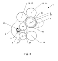
- Fig. 3 shows the drive device 1 in a position in which the first functional unit 11 and the third functional unit 13 are operatively connected in a driveable manner to the motor 2.
- the motor 2 is configured as a rotary motor for regulated driving of the three functional units, the first functional unit 11, the second functional unit 12 and/or the third functional unit 13, and can be configured, for example, as a DC motor, as an AC motor, as a servomotor and/or as a universal motor.
- a motor pinion 23 of the motor 2 may be operatively connected merely to the first functional unit 11, by means of a first transmission mechanism 3 in a first direction of rotation 21, and for the motor pinion 23 to be operatively connected to the first functional unit 11 and a second transmission mechanism 4, which is selectively coupleable to the second functional unit 12 or to the third functional unit 13 by means of an adjustment mechanism 5, by means of the first transmission mechanism 3 in a second direction of rotation 22 opposing the first direction of rotation 21.
- the first functional unit 11 can be driven by means of a first transmission mechanism 13 on rotation of the motor pinion 23 of the motor 2 in a first direction of rotation 21, and the first functional unit 11 and also a second transmission mechanism 4, which is selectively coupleable to the second functional unit 12 or to the third functional unit 13 by means of an adjustment mechanism 5, are driven on rotation of the motor pinion 23 in a second direction of rotation 22 opposing the first direction of rotation 21.
- An advantage of this is that merely the one motor 2 can drive either merely the first functional unit 11, or the first functional unit 11 and the second functional unit 12 or the third functional unit 13, thus allowing all of the operating states of the printing unit to be provided by means of the first motor.
- the printing unit can be configured in a simple, low-weight and cost-effective manner.
- the fact that the motor pinion 23 of the motor 2 is operatively connected merely to the first functional unit 11 in the first direction of rotation 21 can be controlled, for example by an actuator (not shown in the figure).
- the actuator can form, as a function of a direction of the flow of current through the actuator, a first position - for operative connection of the motor pinion 23 to merely the first functional unit 11 - or a second position which differs from the first position - for operative connection of the motor pinion 23 to the first functional unit 11 and the second transmission mechanism 4.
- the motor pinion 23 is rotatable in both directions of rotation, i.e. in the first direction of rotation 21 and in the second direction of rotation 22 opposing the first direction of rotation 21, in particular at a predefinable variable rotational speed, the direction of rotation and the rotational speed of the motor pinion 23 of the motor 2 being, in particular, regulable by means of a control unit.
- the motor pinion 23 is operatively connected to the first transmission mechanism 3 at all times, wherein the motor pinion 23 of the motor 2 and/or of the transmission mechanism 3 can be detachably configured, for example, for replacing the motor and/or for replacing the transmission mechanism.
- the first transmission mechanism 3 may be arranged so as to be pivotable about the motor pinion 23. This ensures that when the direction of rotation of the motor pinion 23 changes, the first transmission mechanism 3 is pivoted about the motor pinion 23, the engagement of the first drive wheel 31 and/or the second drive wheel 32 being changed.
- the operative connection of the motor pinion 23 to the first functional unit 11 or to the first functional unit 11 and the second transmission mechanism 4 can in this case be self-controlling, the first transmission mechanism 3 also rotating up to a predefinable stop in the respective direction with the direction of rotation of the motor pinion 23.
- the first transmission mechanism 3 assumes in this case two preferred positions, the first transmission position of the first transmission mechanism 3 - which is shown in Fig.
- the gear-wheels of the first transmission mechanism 3 are operatively connected either merely to the first gear-wheel 16 of the first functional unit 11 or to the first gear-wheel 16 and to gear-wheels of the second transmission mechanism 4.
- the first transmission mechanism 3 may comprise a first drive wheel 31 and a second drive wheel 32 and for the first drive wheel 31 and the second drive wheel 32 to be configured for rotation in opposite directions. This ensures that both in the first direction of rotation 21 and in the second direction of rotation 22 of the motor pinion 23, the first functional unit 11 is driven in the same direction of rotation.
- this will be described again in greater detail based on the example of the preferred embodiment illustrated in Fig. 1 to 3 .
- the motor pinion 23 rotates in the first direction of rotation 21, as a result of which the first drive wheel 31 rotates in the second direction of rotation 22 and the first gear-wheel 16 rotates in the first direction of rotation 21.
- the second drive wheel 32 can be arranged without engagement to the functional units.
- the motor pinion 23 then rotates in the direction of rotation 22, as a result of which the first drive wheel 31 - which, in the second transmission position of the first transmission mechanism 3, is not operatively connected to the first functional unit 11 - rotates in the first direction of rotation 21.
- the intermediate wheel 33 causes the second drive wheel 32 - which is then operatively connected to the first functional unit 11 - to rotate in the second direction of rotation 22, as a result of which the first gear-wheel 16 rotates, in turn, in the first direction of rotation 21.
- the preferred embodiment of the drive device 1 thus ensures that the first gear-wheel 16 of the first functional unit 11 is rotated, both in the first direction of rotation 21 and in the second direction of rotation 22 of the motor pinion 23, in the first direction of rotation 21, and thus always in the same direction of rotation, thus ensuring reliable driving of the first functional group 11.
- the adjustment mechanism 5 is provided for adjusting the second transmission mechanism 4.
- the position of the adjustment mechanism 5, which preferably has a first adjusted position - shown in Fig. 1 and 3 - and a second adjusted position - shown in Fig. 2 - is provided for controlling the operative connection between the second transmission mechanism 4 and the second functional unit 12 or the third functional unit 13.
- the second transmission mechanism 4 is operatively connected to the third functional unit 13, thus allowing the second transmission mechanism 4 to drive the third functional unit 13.
- the second transmission mechanism 4 is operatively connected to the second functional unit 13, thus allowing the second transmission mechanism 4 to drive the third functional unit 13.
- the adjustment mechanism 5 may preferably be configured - as shown in Fig. 1 to 3 - in the form of a clamp having two blocking teeth, wherein a first blocking tooth 51 can block in the first adjusted position a portion of the second transmission mechanism 4 and wherein a second blocking tooth 52 can block in the second adjusted position another portion of the second transmission mechanism 4.
- the drive of the second functional unit 12 or the third functional unit 13 can thus easily be blocked, as a result of which it is easy to select - provided that the motor pinion 23 is operatively connected to the second transmission mechanism 4 - between the drive of the third functional unit 13 and the drive of the second functional unit 12.
- the second transmission mechanism 4 may be a planetary transmission mechanism 41.
- the first portion of the second transmission mechanism 4 is operatively connected substantially permanently to the second gear-wheel 17 of the second functional means 12 and the second portion of the second transmission mechanism 4 is operatively connected substantially permanently to the third gear-wheel 18 of the third functional means 13.
- the second transmission mechanism 4 in the first adjusted position the second transmission mechanism 4 is operatively connected to the third functional unit 13 and in the second adjusted position the second transmission mechanism 4 is operatively connected to the second functional unit 13.
- the adjustment mechanism 5 in a further embodiment (not shown) of the adjustment mechanism 5, provision is made for the adjustment mechanism 5 to be configured as an actuator and for the actuator preferably to bring a connecting gear-wheel (not shown) into a first position, for driving the second functional unit 12, or into a second position, for driving the second functional unit 12.
- a connecting gear-wheel not shown
- the adjustment mechanism 5 may be actuated by means of the motor 2, the adjustment mechanism 5 being actuable by means of the motor 2. This allows the operating state of the printing unit to be controlled in an especially simple manner and the number of movable parts of the printing unit to be kept low.
- the second functional unit 12 and the third functional unit 13 can also be driven simultaneously, at least from time to time.
- additional elements of the printing unit can also be allocated to the functional units 11, 12, 13 and be driven therewith.
Landscapes
- Transmission Devices (AREA)
- Electrophotography Configuration And Component (AREA)
Abstract
Description
- The invention relates to a drive device according to the preamble of
claim 1. - Drive devices are known in printing units, for example in printers, fax devices and/or copiers. The drive devices drive differing functional units, a first functional unit comprising a toner, a printer cartridge and an output means, a second functional unit comprising a receiving roll and a third functional unit comprising a conveyor means, the various functional units being required at differing moments in the printing process and thus having to be driven in differing directions of rotation and at differing speed. A drawback of this is that the known printing units are heavy and take up a lot of space for the required drive.
- The object of the invention is therefore to specify a drive device of the type mentioned at the outset that allows the aforementioned drawbacks to be avoided, that is simple and reliable in its construction, is light and can be manufactured cost-effectively.
- According to the invention, this is achieved by the features of
claim 1. - This gives rise to the advantage that there is configured in the drive unit merely one drive motor which can drive all the differing functional groups. In this case, three functional groups can be driven differently with merely one motor. This motor can ensure a short switching time, coordination of the start-up and shut-down times of a plurality of motors not being required. Furthermore, the number of adjusting units required can be kept low, so the probability of failure is low.
- The fact that further motors are not used for the purposes of driving gives rise, in particular, to the advantages, that the drive device takes up little space, that the activator and the activation electronics can be manufactured simply and cost-effectively, that the power consumed by the drive device can be kept low and that the noise of the drive device is reduced.
- As a result of the provision of just one motor for the purposes of driving, compared to a plurality of motors, the quality of the motor can be improved while the manufacturing costs are lowered, as a result of which the formation of heat, the formation of noise and the amount of energy required can be especially low. Furthermore, a long service life and high reliability of the drive device are easily ensured.
- The invention further relates to a method according to the preamble of
claim 5. - A further object of the invention is to specify a method with which the advantages of the drive device described at the outset can be provided simply and cost-effectively.
- According to the invention, this is achieved by the features of
claim 5. - The sub-claims, which at the same time, like
claim 1 and claim 5, form part of the description, relate to further advantageous configurations of the invention. - The invention will be described in greater detail with reference to the appended drawings which show, by way of example, merely preferred embodiments and in which:
-
Fig. 1 is a schematic side view of a drive device according to a first embodiment in a first transmission position of a first transmission mechanism and in a first adjusted position of an adjustment mechanism; -
Fig. 2 is a schematic side view of the drive device according toFig. 1 in a second transmission position of the first transmission mechanism and in a second adjusted position of the adjustment mechanism; and -
Fig. 3 is a schematic side view of the drive device according toFig. 1 in the second transmission position of the first transmission mechanism and in the first adjusted position of the adjustment mechanism. -
Fig. 1 to 3 show adrive device 1 according to a preferred embodiment for a printing unit comprising a first functional unit 11, a second functional unit 12 and a third functional unit 13, the first functional unit 11 comprising a toner, a printer cartridge and an output means, the second functional unit 12 comprising a receiving roll and the third functional unit 13 comprising a conveyor means, acommon motor 2 being configured for regulated driving of the first functional unit 11, the second functional unit 12 and the third functional unit 13. - The
drive device 1 facilitates a method for operating a printing unit in which the first functional unit 11, the second functional unit 12 and the third functional unit 13 are driven, the first functional unit 11 comprising a toner, a printer cartridge and an output means, the second functional unit 12 comprising a receiving roll and a third functional unit 13 comprising a conveyor means, and the first functional unit 11, the second functional unit 12 and the third functional unit 13 being driven by means of acommon motor 2. - The
drive device 1 may advantageously drive all of the components to be driven, in particular the first functional unit 11, the second functional unit 12 and the third functional unit 13 and also the associated transmission mechanisms and gear-wheels, of the printing unit. - The illustrated
preferred drive device 1 and the method facilitated by thedrive device 1 give rise to the advantages and advantageous effects mentioned in the introductory part of the description. -
Fig. 1 to 3 show the first functional unit 11, the second functional unit 12 and the third functional unit 13, merely the gear-wheels which are coupleable to thefirst transmission mechanism 3 or thesecond transmission mechanism 4, the first gear-wheel 16, the second gear-wheel 17 and the third gear-wheel 18 of these functional units being shown. In this case, the first gear-wheel 16 is operatively connected to movable parts of the first functional unit 11, the second gear-wheel 17 is operatively connected to movable parts of the second functional unit 12 and the third gear-wheel 18 is operatively connected to movable parts of the third functional unit 13. - The printing unit may, for example, be configured as a laser printer, as an ink-jet printer, as a fax machine, as a copier and/or as a thermal sublimation printer and also as a black-and-white printer or as a colour printer. The printing unit is provided for the imprinting of received media, preferably of sheets. The sheets which are preferably used can advantageously comprise paper and/or plastics material film and can advantageously have standard sizes, for example the size of "A6" to "A2", in particular "A4", "US legal" and/or "US letter".
- The printing device can be divided into functional groups, the division preferably being made into the functional group for imprinting, which is referred to as the first functional unit 11, into the functional group for receiving the received medium, preferably the sheet, which is referred to as the second functional unit 12, and into the functional group for conveying the received medium, preferably the sheet, along a path of conveyance through the printing unit, which is referred to as the third functional unit 12.
- Over the course of a printing process, i.e. in the sequence of the process from receiving via imprinting up to ejection of the received medium, preferably the sheet, the differing functional units place differing requirements on the direction of rotation and/or the rotational speed of the movable parts in the functional units, the various functional units being required at differing moments in the printing process and thus having to be driven in differing directions of rotation and at differing speed.
-
Fig. 1 shows thedrive device 1 in a position in which merely the first functional unit 11 is operatively connected in a driveable manner to themotor 2. -
Fig. 2 shows thedrive device 1 in a position in which the first functional unit 11 and the second functional unit 12 are operatively connected in a driveable manner to themotor 2. -
Fig. 3 shows thedrive device 1 in a position in which the first functional unit 11 and the third functional unit 13 are operatively connected in a driveable manner to themotor 2. - The
motor 2 is configured as a rotary motor for regulated driving of the three functional units, the first functional unit 11, the second functional unit 12 and/or the third functional unit 13, and can be configured, for example, as a DC motor, as an AC motor, as a servomotor and/or as a universal motor. - Preferably, provision may be made for a
motor pinion 23 of themotor 2 to be operatively connected merely to the first functional unit 11, by means of afirst transmission mechanism 3 in a first direction ofrotation 21, and for themotor pinion 23 to be operatively connected to the first functional unit 11 and asecond transmission mechanism 4, which is selectively coupleable to the second functional unit 12 or to the third functional unit 13 by means of anadjustment mechanism 5, by means of thefirst transmission mechanism 3 in a second direction ofrotation 22 opposing the first direction ofrotation 21. As a result, merely the first functional unit 11 can be driven by means of a first transmission mechanism 13 on rotation of themotor pinion 23 of themotor 2 in a first direction ofrotation 21, and the first functional unit 11 and also asecond transmission mechanism 4, which is selectively coupleable to the second functional unit 12 or to the third functional unit 13 by means of anadjustment mechanism 5, are driven on rotation of themotor pinion 23 in a second direction ofrotation 22 opposing the first direction ofrotation 21. An advantage of this is that merely the onemotor 2 can drive either merely the first functional unit 11, or the first functional unit 11 and the second functional unit 12 or the third functional unit 13, thus allowing all of the operating states of the printing unit to be provided by means of the first motor. As a result, the printing unit can be configured in a simple, low-weight and cost-effective manner. - The fact that the
motor pinion 23 of themotor 2 is operatively connected merely to the first functional unit 11 in the first direction ofrotation 21 can be controlled, for example by an actuator (not shown in the figure). For example, the actuator can form, as a function of a direction of the flow of current through the actuator, a first position - for operative connection of themotor pinion 23 to merely the first functional unit 11 - or a second position which differs from the first position - for operative connection of themotor pinion 23 to the first functional unit 11 and thesecond transmission mechanism 4. - The
motor pinion 23 is rotatable in both directions of rotation, i.e. in the first direction ofrotation 21 and in the second direction ofrotation 22 opposing the first direction ofrotation 21, in particular at a predefinable variable rotational speed, the direction of rotation and the rotational speed of themotor pinion 23 of themotor 2 being, in particular, regulable by means of a control unit. - According to the preferred embodiment, the
motor pinion 23 is operatively connected to thefirst transmission mechanism 3 at all times, wherein themotor pinion 23 of themotor 2 and/or of thetransmission mechanism 3 can be detachably configured, for example, for replacing the motor and/or for replacing the transmission mechanism. - In the preferred embodiment, provision may be made for the
first transmission mechanism 3 to be arranged so as to be pivotable about themotor pinion 23. This ensures that when the direction of rotation of themotor pinion 23 changes, thefirst transmission mechanism 3 is pivoted about themotor pinion 23, the engagement of thefirst drive wheel 31 and/or thesecond drive wheel 32 being changed. The operative connection of themotor pinion 23 to the first functional unit 11 or to the first functional unit 11 and thesecond transmission mechanism 4 can in this case be self-controlling, thefirst transmission mechanism 3 also rotating up to a predefinable stop in the respective direction with the direction of rotation of themotor pinion 23. Thefirst transmission mechanism 3 assumes in this case two preferred positions, the first transmission position of the first transmission mechanism 3 - which is shown inFig. 1 - being formed in the first direction ofrotation 21 of themotor pinion 23 and the second transmission position of the first transmission mechanism 3 - which is shown inFig. 2 and3 - being formed in the second direction ofrotation 22 of themotor pinion 23. As a result of the respective transmission position of thefirst transmission mechanism 3, the gear-wheels of thefirst transmission mechanism 3 are operatively connected either merely to the first gear-wheel 16 of the first functional unit 11 or to the first gear-wheel 16 and to gear-wheels of thesecond transmission mechanism 4. - In an advantageous development, provision may be made for the
first transmission mechanism 3 to comprise afirst drive wheel 31 and asecond drive wheel 32 and for thefirst drive wheel 31 and thesecond drive wheel 32 to be configured for rotation in opposite directions. This ensures that both in the first direction ofrotation 21 and in the second direction ofrotation 22 of themotor pinion 23, the first functional unit 11 is driven in the same direction of rotation. - According to the preferred embodiment, provision is made for when the
motor pinion 23 is driven in the first direction ofrotation 21, thefirst drive wheel 31 to be operatively connected to the first functional unit 11 and for when themotor pinion 23 is driven in the second direction ofrotation 22, thefirst drive wheel 31 to be operatively connected to thesecond transmission mechanism 4 and thesecond drive wheel 32 to be operatively connected to the first functional unit 11. In the following paragraph, this will be described again in greater detail based on the example of the preferred embodiment illustrated inFig. 1 to 3 . - In the preferred first transmission position - shown in
Fig. 1 - themotor pinion 23 rotates in the first direction ofrotation 21, as a result of which thefirst drive wheel 31 rotates in the second direction ofrotation 22 and the first gear-wheel 16 rotates in the first direction ofrotation 21. In the first transmission position, thesecond drive wheel 32 can be arranged without engagement to the functional units. After reversal of the direction of rotation of the motor pinion 23 - shown inFig. 2 and3 - into the second direction ofrotation 22, the entire transmission mechanism pivots about an, in particular, common axis of rotation with themotor pinion 23 into the preferred second transmission position of thefirst transmission mechanism 3. Themotor pinion 23 then rotates in the direction ofrotation 22, as a result of which the first drive wheel 31 - which, in the second transmission position of thefirst transmission mechanism 3, is not operatively connected to the first functional unit 11 - rotates in the first direction ofrotation 21. Theintermediate wheel 33 causes the second drive wheel 32 - which is then operatively connected to the first functional unit 11 - to rotate in the second direction ofrotation 22, as a result of which the first gear-wheel 16 rotates, in turn, in the first direction ofrotation 21. The preferred embodiment of thedrive device 1 thus ensures that the first gear-wheel 16 of the first functional unit 11 is rotated, both in the first direction ofrotation 21 and in the second direction ofrotation 22 of themotor pinion 23, in the first direction ofrotation 21, and thus always in the same direction of rotation, thus ensuring reliable driving of the first functional group 11. - In the preferred embodiment, the
adjustment mechanism 5 is provided for adjusting thesecond transmission mechanism 4. The position of theadjustment mechanism 5, which preferably has a first adjusted position - shown inFig. 1 and3 - and a second adjusted position - shown inFig. 2 - is provided for controlling the operative connection between thesecond transmission mechanism 4 and the second functional unit 12 or the third functional unit 13. - In the first adjusted position of the
adjustment mechanism 5, thesecond transmission mechanism 4 is operatively connected to the third functional unit 13, thus allowing thesecond transmission mechanism 4 to drive the third functional unit 13. - In the second adjusted position of the
adjustment mechanism 5, thesecond transmission mechanism 4 is operatively connected to the second functional unit 13, thus allowing thesecond transmission mechanism 4 to drive the third functional unit 13. - The
adjustment mechanism 5 may preferably be configured - as shown inFig. 1 to 3 - in the form of a clamp having two blocking teeth, wherein afirst blocking tooth 51 can block in the first adjusted position a portion of thesecond transmission mechanism 4 and wherein asecond blocking tooth 52 can block in the second adjusted position another portion of thesecond transmission mechanism 4. The drive of the second functional unit 12 or the third functional unit 13 can thus easily be blocked, as a result of which it is easy to select - provided that themotor pinion 23 is operatively connected to the second transmission mechanism 4 - between the drive of the third functional unit 13 and the drive of the second functional unit 12. - In an advantageous development, provision may be made for the
second transmission mechanism 4 to be aplanetary transmission mechanism 41. This allows thesecond transmission mechanism 4 to be particularly compact in its configuration. Also, this allows, by blocking of a first portion of the second transmission mechanism 4 (for example, by means of the first blocking tooth 51), a second portion of thesecond transmission mechanism 4 to be driven and, conversely, by blocking of the second portion of the second transmission mechanism 4 (for example, by means of the second blocking tooth 52), a first portion of thesecond transmission mechanism 4 to be driven. Advantageously, in this case, the first portion of thesecond transmission mechanism 4 is operatively connected substantially permanently to the second gear-wheel 17 of the second functional means 12 and the second portion of thesecond transmission mechanism 4 is operatively connected substantially permanently to the third gear-wheel 18 of the third functional means 13. Thus, in this case too, in the first adjusted position thesecond transmission mechanism 4 is operatively connected to the third functional unit 13 and in the second adjusted position thesecond transmission mechanism 4 is operatively connected to the second functional unit 13. - In a further embodiment (not shown) of the
adjustment mechanism 5, provision is made for theadjustment mechanism 5 to be configured as an actuator and for the actuator preferably to bring a connecting gear-wheel (not shown) into a first position, for driving the second functional unit 12, or into a second position, for driving the second functional unit 12. This allows - for forming the drive of the second functional unit 12 or the third functional unit 13 - merely a portion of thesecond transmission mechanism 4 to be driven instead of blocking of a portion of thesecond transmission mechanism 4. - In an advantageous development of the
drive unit 1, provision may be made for theadjustment mechanism 5 to be actuated by means of themotor 2, theadjustment mechanism 5 being actuable by means of themotor 2. This allows the operating state of the printing unit to be controlled in an especially simple manner and the number of movable parts of the printing unit to be kept low. - In a further embodiment, the second functional unit 12 and the third functional unit 13 can also be driven simultaneously, at least from time to time.
- In further embodiments, additional elements of the printing unit can also be allocated to the functional units 11, 12, 13 and be driven therewith.
- Further embodiments according to the invention display merely some of the described features, wherein any combination of features, especially a combination of various described embodiments, may be provided.
Claims (10)
- Drive device (1) for a printing unit comprising a first functional unit (11), a second functional unit (12) and a third functional unit (13), the first functional unit (11) comprising a toner, a printer cartridge and an output means, the second functional unit (12) comprising a receiving roll and the third functional unit (13) comprising a conveyor means, characterised in that a common motor (2) is configured for regulated driving of the first functional unit (11), the second functional unit (12) and the third functional unit (13).
- Drive device according to claim 1, characterised in that a motor pinion (23) of the motor (2) is operatively connected merely to the first functional unit (11), by means of a first transmission mechanism (3) in a first direction of rotation (21), and in that the motor pinion (23) is operatively connected to the first functional unit (11) and a second transmission mechanism (4), which is selectively coupleable to the second functional unit (12) or to the third functional unit (13) by means of an adjustment mechanism (5), by means of the first transmission mechanism (3) in a second direction of rotation (22) opposing the first direction of rotation (21).
- Drive device according to claim 2, characterised in that the first transmission mechanism (3) comprises a first drive wheel (31) and a second drive wheel (32) and in that the first drive wheel (31) and the second drive wheel (32) are configured for rotation in opposite directions.
- Drive device according to either claim 2 or claim 3, characterised in that the first transmission mechanism (3) is arranged so as to be pivotable about the motor pinion (23).
- Drive device according to either claim 2, 3 or claim 4, characterised in that when the motor pinion (23) is driven in the first direction of rotation (21), the first drive wheel (31) is operatively connected to the first functional unit (11) and in that when the motor pinion (23) is driven in the second direction of rotation (22), the first drive wheel (31) is operatively connected to the second transmission mechanism (4) and the second drive wheel (32) is operatively connected to the first functional unit (11).
- Drive device according to any one of claims 2 to 5, characterised in that the second transmission mechanism (4) is a planetary transmission mechanism (41).
- Method for operating a printing unit in which a first functional unit (11), a second functional unit (12) and a third functional unit (13) are driven, the first functional unit (11) comprising a toner, a printer cartridge and an output means, the second functional unit (12) comprising a receiving roll and a third functional unit (13) comprising a conveyor means, characterised in that the first functional unit (11), the second functional unit (12) and the third functional unit (13) are driven by means of a common motor (2).
- Method according to claim 7, characterised in that merely the first functional unit (11) is driven on rotation of a motor pinion (23) of the motor (2) in a first direction of rotation (21) by means of a first transmission mechanism (3) and in that on rotation of the motor pinion (23) in a second direction of rotation (22) opposing the first direction of rotation (21), the first functional unit (11) and a second transmission mechanism (4), which is selectively coupleable to the second functional unit (12) or to the third functional unit (13) by means of an adjustment mechanism (5), are driven.
- Method according to either claim 7 or claim 8, characterised in that when the direction of rotation of the motor pinion (23) is changed, the first transmission mechanism (3) is pivoted about the motor pinion (23), the engagement of the first drive wheel (31) and/or the second drive wheel (32) being changed.
- Method according to claims 8 or claim 9, characterised in that the adjustment mechanism (5) is actuated by means of the motor (2).
Priority Applications (3)
| Application Number | Priority Date | Filing Date | Title |
|---|---|---|---|
| ES07291343T ES2386736T3 (en) | 2007-11-07 | 2007-11-07 | Drive device |
| AT07291343T ATE554940T1 (en) | 2007-11-07 | 2007-11-07 | DRIVE DEVICE |
| EP07291343A EP2058137B1 (en) | 2007-11-07 | 2007-11-07 | Drive device |
Applications Claiming Priority (1)
| Application Number | Priority Date | Filing Date | Title |
|---|---|---|---|
| EP07291343A EP2058137B1 (en) | 2007-11-07 | 2007-11-07 | Drive device |
Publications (2)
| Publication Number | Publication Date |
|---|---|
| EP2058137A1 true EP2058137A1 (en) | 2009-05-13 |
| EP2058137B1 EP2058137B1 (en) | 2012-04-25 |
Family
ID=39155510
Family Applications (1)
| Application Number | Title | Priority Date | Filing Date |
|---|---|---|---|
| EP07291343A Not-in-force EP2058137B1 (en) | 2007-11-07 | 2007-11-07 | Drive device |
Country Status (3)
| Country | Link |
|---|---|
| EP (1) | EP2058137B1 (en) |
| AT (1) | ATE554940T1 (en) |
| ES (1) | ES2386736T3 (en) |
Cited By (1)
| Publication number | Priority date | Publication date | Assignee | Title |
|---|---|---|---|---|
| JP2015068470A (en) * | 2013-09-30 | 2015-04-13 | キヤノン株式会社 | Driving force switching mechanism and image forming apparatus |
Citations (3)
| Publication number | Priority date | Publication date | Assignee | Title |
|---|---|---|---|---|
| EP0186212A2 (en) * | 1984-12-28 | 1986-07-02 | Brother Kogyo Kabushiki Kaisha | Printer with a motor controlled by chopping means |
| US6082912A (en) * | 1999-01-29 | 2000-07-04 | Mitsubishi Denki Kabushiki Kaisha | Thermal printer with a mode changing gear |
| US20040251610A1 (en) * | 2001-08-31 | 2004-12-16 | Seiko Epson Corporation | Recording apparatus |
-
2007
- 2007-11-07 EP EP07291343A patent/EP2058137B1/en not_active Not-in-force
- 2007-11-07 ES ES07291343T patent/ES2386736T3/en active Active
- 2007-11-07 AT AT07291343T patent/ATE554940T1/en active
Patent Citations (3)
| Publication number | Priority date | Publication date | Assignee | Title |
|---|---|---|---|---|
| EP0186212A2 (en) * | 1984-12-28 | 1986-07-02 | Brother Kogyo Kabushiki Kaisha | Printer with a motor controlled by chopping means |
| US6082912A (en) * | 1999-01-29 | 2000-07-04 | Mitsubishi Denki Kabushiki Kaisha | Thermal printer with a mode changing gear |
| US20040251610A1 (en) * | 2001-08-31 | 2004-12-16 | Seiko Epson Corporation | Recording apparatus |
Cited By (1)
| Publication number | Priority date | Publication date | Assignee | Title |
|---|---|---|---|---|
| JP2015068470A (en) * | 2013-09-30 | 2015-04-13 | キヤノン株式会社 | Driving force switching mechanism and image forming apparatus |
Also Published As
| Publication number | Publication date |
|---|---|
| EP2058137B1 (en) | 2012-04-25 |
| ES2386736T3 (en) | 2012-08-28 |
| ATE554940T1 (en) | 2012-05-15 |
Similar Documents
| Publication | Publication Date | Title |
|---|---|---|
| JP5469327B2 (en) | Method for operating the printing unit of a printing press | |
| JP4820314B2 (en) | Paper feeder | |
| JP5817281B2 (en) | Image forming apparatus | |
| CN101279546A (en) | Feed drive device for printing machine and printing machine | |
| US8529018B2 (en) | Recording apparatus | |
| EP2347902B1 (en) | Intermediate transfer medium conveying device and thermal transfer line printer using the same | |
| US10081189B2 (en) | Recording apparatus | |
| EP1129969B1 (en) | Sheet material conveying apparatus and recording apparatus | |
| EP2058137B1 (en) | Drive device | |
| JP2011526234A (en) | Printed sheet processing machine, especially sheet discharge device for rotary printing machines | |
| JPH1035964A (en) | Paper transport mechanism, image recording apparatus provided with the same, and image reading and recording apparatus | |
| JPH11282224A (en) | Gear type power transmission device in image forming apparatus | |
| JP2000198599A (en) | Printing press folder feeding device | |
| CN111511564B (en) | Medium cutting device and method | |
| JP2011500364A (en) | Method for driving a printing press | |
| JP4548362B2 (en) | Recording medium feeding apparatus, recording apparatus, and liquid ejecting apparatus | |
| JP2008049677A (en) | Printer device | |
| JP3252908U (en) | Paper separation structure | |
| JP4343036B2 (en) | Printer | |
| JP2861436B2 (en) | Printer paper feed mechanism | |
| JP2004291603A (en) | Rotary cutter paper ejection device | |
| EP1661725A2 (en) | Image forming apparatus | |
| JP2000135774A (en) | Printer | |
| EP0446840B1 (en) | Automatic paper feed apparatus | |
| JPH03238242A (en) | Paper feeder |
Legal Events
| Date | Code | Title | Description |
|---|---|---|---|
| PUAI | Public reference made under article 153(3) epc to a published international application that has entered the european phase |
Free format text: ORIGINAL CODE: 0009012 |
|
| AK | Designated contracting states |
Kind code of ref document: A1 Designated state(s): AT BE BG CH CY CZ DE DK EE ES FI FR GB GR HU IE IS IT LI LT LU LV MC MT NL PL PT RO SE SI SK TR |
|
| AX | Request for extension of the european patent |
Extension state: AL BA HR MK RS |
|
| 17P | Request for examination filed |
Effective date: 20090703 |
|
| RAP1 | Party data changed (applicant data changed or rights of an application transferred) |
Owner name: SAGEM COMMUNICATIONS |
|
| AKX | Designation fees paid |
Designated state(s): AT BE BG CH CY CZ DE DK EE ES FI FR GB GR HU IE IS IT LI LT LU LV MC MT NL PL PT RO SE SI SK TR |
|
| RAP1 | Party data changed (applicant data changed or rights of an application transferred) |
Owner name: SAGECOM DOCUMENTS SAS |
|
| RAP1 | Party data changed (applicant data changed or rights of an application transferred) |
Owner name: SAGEMCOM DOCUMENTS SAS |
|
| GRAP | Despatch of communication of intention to grant a patent |
Free format text: ORIGINAL CODE: EPIDOSNIGR1 |
|
| GRAS | Grant fee paid |
Free format text: ORIGINAL CODE: EPIDOSNIGR3 |
|
| GRAA | (expected) grant |
Free format text: ORIGINAL CODE: 0009210 |
|
| AK | Designated contracting states |
Kind code of ref document: B1 Designated state(s): AT BE BG CH CY CZ DE DK EE ES FI FR GB GR HU IE IS IT LI LT LU LV MC MT NL PL PT RO SE SI SK TR |
|
| REG | Reference to a national code |
Ref country code: GB Ref legal event code: FG4D |
|
| REG | Reference to a national code |
Ref country code: CH Ref legal event code: EP |
|
| REG | Reference to a national code |
Ref country code: AT Ref legal event code: REF Ref document number: 554940 Country of ref document: AT Kind code of ref document: T Effective date: 20120515 |
|
| REG | Reference to a national code |
Ref country code: IE Ref legal event code: FG4D |
|
| REG | Reference to a national code |
Ref country code: DE Ref legal event code: R096 Ref document number: 602007022227 Country of ref document: DE Effective date: 20120621 |
|
| REG | Reference to a national code |
Ref country code: NL Ref legal event code: VDEP Effective date: 20120425 |
|
| REG | Reference to a national code |
Ref country code: ES Ref legal event code: FG2A Ref document number: 2386736 Country of ref document: ES Kind code of ref document: T3 Effective date: 20120828 |
|
| REG | Reference to a national code |
Ref country code: AT Ref legal event code: MK05 Ref document number: 554940 Country of ref document: AT Kind code of ref document: T Effective date: 20120425 |
|
| LTIE | Lt: invalidation of european patent or patent extension |
Effective date: 20120425 |
|
| PG25 | Lapsed in a contracting state [announced via postgrant information from national office to epo] |
Ref country code: IS Free format text: LAPSE BECAUSE OF FAILURE TO SUBMIT A TRANSLATION OF THE DESCRIPTION OR TO PAY THE FEE WITHIN THE PRESCRIBED TIME-LIMIT Effective date: 20120825 Ref country code: LT Free format text: LAPSE BECAUSE OF FAILURE TO SUBMIT A TRANSLATION OF THE DESCRIPTION OR TO PAY THE FEE WITHIN THE PRESCRIBED TIME-LIMIT Effective date: 20120425 Ref country code: FI Free format text: LAPSE BECAUSE OF FAILURE TO SUBMIT A TRANSLATION OF THE DESCRIPTION OR TO PAY THE FEE WITHIN THE PRESCRIBED TIME-LIMIT Effective date: 20120425 Ref country code: CY Free format text: LAPSE BECAUSE OF FAILURE TO SUBMIT A TRANSLATION OF THE DESCRIPTION OR TO PAY THE FEE WITHIN THE PRESCRIBED TIME-LIMIT Effective date: 20120425 Ref country code: PL Free format text: LAPSE BECAUSE OF FAILURE TO SUBMIT A TRANSLATION OF THE DESCRIPTION OR TO PAY THE FEE WITHIN THE PRESCRIBED TIME-LIMIT Effective date: 20120425 Ref country code: SE Free format text: LAPSE BECAUSE OF FAILURE TO SUBMIT A TRANSLATION OF THE DESCRIPTION OR TO PAY THE FEE WITHIN THE PRESCRIBED TIME-LIMIT Effective date: 20120425 |
|
| PG25 | Lapsed in a contracting state [announced via postgrant information from national office to epo] |
Ref country code: SI Free format text: LAPSE BECAUSE OF FAILURE TO SUBMIT A TRANSLATION OF THE DESCRIPTION OR TO PAY THE FEE WITHIN THE PRESCRIBED TIME-LIMIT Effective date: 20120425 Ref country code: PT Free format text: LAPSE BECAUSE OF FAILURE TO SUBMIT A TRANSLATION OF THE DESCRIPTION OR TO PAY THE FEE WITHIN THE PRESCRIBED TIME-LIMIT Effective date: 20120827 Ref country code: LV Free format text: LAPSE BECAUSE OF FAILURE TO SUBMIT A TRANSLATION OF THE DESCRIPTION OR TO PAY THE FEE WITHIN THE PRESCRIBED TIME-LIMIT Effective date: 20120425 Ref country code: GR Free format text: LAPSE BECAUSE OF FAILURE TO SUBMIT A TRANSLATION OF THE DESCRIPTION OR TO PAY THE FEE WITHIN THE PRESCRIBED TIME-LIMIT Effective date: 20120726 |
|
| PG25 | Lapsed in a contracting state [announced via postgrant information from national office to epo] |
Ref country code: BE Free format text: LAPSE BECAUSE OF FAILURE TO SUBMIT A TRANSLATION OF THE DESCRIPTION OR TO PAY THE FEE WITHIN THE PRESCRIBED TIME-LIMIT Effective date: 20120425 |
|
| PG25 | Lapsed in a contracting state [announced via postgrant information from national office to epo] |
Ref country code: AT Free format text: LAPSE BECAUSE OF FAILURE TO SUBMIT A TRANSLATION OF THE DESCRIPTION OR TO PAY THE FEE WITHIN THE PRESCRIBED TIME-LIMIT Effective date: 20120425 Ref country code: EE Free format text: LAPSE BECAUSE OF FAILURE TO SUBMIT A TRANSLATION OF THE DESCRIPTION OR TO PAY THE FEE WITHIN THE PRESCRIBED TIME-LIMIT Effective date: 20120425 Ref country code: NL Free format text: LAPSE BECAUSE OF FAILURE TO SUBMIT A TRANSLATION OF THE DESCRIPTION OR TO PAY THE FEE WITHIN THE PRESCRIBED TIME-LIMIT Effective date: 20120425 Ref country code: CZ Free format text: LAPSE BECAUSE OF FAILURE TO SUBMIT A TRANSLATION OF THE DESCRIPTION OR TO PAY THE FEE WITHIN THE PRESCRIBED TIME-LIMIT Effective date: 20120425 Ref country code: SK Free format text: LAPSE BECAUSE OF FAILURE TO SUBMIT A TRANSLATION OF THE DESCRIPTION OR TO PAY THE FEE WITHIN THE PRESCRIBED TIME-LIMIT Effective date: 20120425 Ref country code: DK Free format text: LAPSE BECAUSE OF FAILURE TO SUBMIT A TRANSLATION OF THE DESCRIPTION OR TO PAY THE FEE WITHIN THE PRESCRIBED TIME-LIMIT Effective date: 20120425 Ref country code: RO Free format text: LAPSE BECAUSE OF FAILURE TO SUBMIT A TRANSLATION OF THE DESCRIPTION OR TO PAY THE FEE WITHIN THE PRESCRIBED TIME-LIMIT Effective date: 20120425 |
|
| PLBE | No opposition filed within time limit |
Free format text: ORIGINAL CODE: 0009261 |
|
| STAA | Information on the status of an ep patent application or granted ep patent |
Free format text: STATUS: NO OPPOSITION FILED WITHIN TIME LIMIT |
|
| 26N | No opposition filed |
Effective date: 20130128 |
|
| REG | Reference to a national code |
Ref country code: DE Ref legal event code: R097 Ref document number: 602007022227 Country of ref document: DE Effective date: 20130128 |
|
| REG | Reference to a national code |
Ref country code: CH Ref legal event code: PL |
|
| PG25 | Lapsed in a contracting state [announced via postgrant information from national office to epo] |
Ref country code: CH Free format text: LAPSE BECAUSE OF NON-PAYMENT OF DUE FEES Effective date: 20121130 Ref country code: BG Free format text: LAPSE BECAUSE OF FAILURE TO SUBMIT A TRANSLATION OF THE DESCRIPTION OR TO PAY THE FEE WITHIN THE PRESCRIBED TIME-LIMIT Effective date: 20120725 Ref country code: LI Free format text: LAPSE BECAUSE OF NON-PAYMENT OF DUE FEES Effective date: 20121130 |
|
| REG | Reference to a national code |
Ref country code: IE Ref legal event code: MM4A |
|
| REG | Reference to a national code |
Ref country code: DE Ref legal event code: R082 Ref document number: 602007022227 Country of ref document: DE Representative=s name: LORENZ & KOLLEGEN PATENTANWAELTE PARTNERSCHAFT, DE |
|
| REG | Reference to a national code |
Ref country code: DE Ref legal event code: R082 Ref document number: 602007022227 Country of ref document: DE Representative=s name: LORENZ & KOLLEGEN PATENTANWAELTE PARTNERSCHAFT, DE Effective date: 20130823 Ref country code: DE Ref legal event code: R081 Ref document number: 602007022227 Country of ref document: DE Owner name: FUNAI ELECTRIC CO., LTD., DAITO-SHI, JP Free format text: FORMER OWNER: SAGEMCOM DOCUMENTS SAS, RUEIL MALMAISON, FR Effective date: 20130823 |
|
| PG25 | Lapsed in a contracting state [announced via postgrant information from national office to epo] |
Ref country code: IE Free format text: LAPSE BECAUSE OF NON-PAYMENT OF DUE FEES Effective date: 20121107 |
|
| REG | Reference to a national code |
Ref country code: FR Ref legal event code: TP Owner name: FUNAI ELECTRIC CO., LTD., JP Effective date: 20131001 |
|
| REG | Reference to a national code |
Ref country code: GB Ref legal event code: 732E Free format text: REGISTERED BETWEEN 20131017 AND 20131023 |
|
| PG25 | Lapsed in a contracting state [announced via postgrant information from national office to epo] |
Ref country code: MT Free format text: LAPSE BECAUSE OF FAILURE TO SUBMIT A TRANSLATION OF THE DESCRIPTION OR TO PAY THE FEE WITHIN THE PRESCRIBED TIME-LIMIT Effective date: 20120425 |
|
| PG25 | Lapsed in a contracting state [announced via postgrant information from national office to epo] |
Ref country code: TR Free format text: LAPSE BECAUSE OF FAILURE TO SUBMIT A TRANSLATION OF THE DESCRIPTION OR TO PAY THE FEE WITHIN THE PRESCRIBED TIME-LIMIT Effective date: 20120425 Ref country code: MC Free format text: LAPSE BECAUSE OF NON-PAYMENT OF DUE FEES Effective date: 20121130 |
|
| PG25 | Lapsed in a contracting state [announced via postgrant information from national office to epo] |
Ref country code: LU Free format text: LAPSE BECAUSE OF NON-PAYMENT OF DUE FEES Effective date: 20121107 |
|
| PG25 | Lapsed in a contracting state [announced via postgrant information from national office to epo] |
Ref country code: HU Free format text: LAPSE BECAUSE OF FAILURE TO SUBMIT A TRANSLATION OF THE DESCRIPTION OR TO PAY THE FEE WITHIN THE PRESCRIBED TIME-LIMIT Effective date: 20071107 |
|
| REG | Reference to a national code |
Ref country code: ES Ref legal event code: PC2A Owner name: FUNAI ELECTRIC CO.LTD Effective date: 20150116 |
|
| REG | Reference to a national code |
Ref country code: FR Ref legal event code: PLFP Year of fee payment: 9 |
|
| PGFP | Annual fee paid to national office [announced via postgrant information from national office to epo] |
Ref country code: GB Payment date: 20151104 Year of fee payment: 9 Ref country code: DE Payment date: 20151103 Year of fee payment: 9 Ref country code: IT Payment date: 20151124 Year of fee payment: 9 |
|
| PGFP | Annual fee paid to national office [announced via postgrant information from national office to epo] |
Ref country code: FR Payment date: 20151008 Year of fee payment: 9 Ref country code: ES Payment date: 20151014 Year of fee payment: 9 |
|
| REG | Reference to a national code |
Ref country code: DE Ref legal event code: R119 Ref document number: 602007022227 Country of ref document: DE |
|
| GBPC | Gb: european patent ceased through non-payment of renewal fee |
Effective date: 20161107 |
|
| REG | Reference to a national code |
Ref country code: FR Ref legal event code: ST Effective date: 20170731 |
|
| PG25 | Lapsed in a contracting state [announced via postgrant information from national office to epo] |
Ref country code: FR Free format text: LAPSE BECAUSE OF NON-PAYMENT OF DUE FEES Effective date: 20161130 Ref country code: IT Free format text: LAPSE BECAUSE OF NON-PAYMENT OF DUE FEES Effective date: 20161107 |
|
| PG25 | Lapsed in a contracting state [announced via postgrant information from national office to epo] |
Ref country code: GB Free format text: LAPSE BECAUSE OF NON-PAYMENT OF DUE FEES Effective date: 20161107 Ref country code: DE Free format text: LAPSE BECAUSE OF NON-PAYMENT OF DUE FEES Effective date: 20170601 |
|
| PG25 | Lapsed in a contracting state [announced via postgrant information from national office to epo] |
Ref country code: ES Free format text: LAPSE BECAUSE OF NON-PAYMENT OF DUE FEES Effective date: 20161108 |
|
| REG | Reference to a national code |
Ref country code: ES Ref legal event code: FD2A Effective date: 20181122 |