EP2057911B1 - Selectable Boot Articulation System - Google Patents
Selectable Boot Articulation System Download PDFInfo
- Publication number
- EP2057911B1 EP2057911B1 EP08168473A EP08168473A EP2057911B1 EP 2057911 B1 EP2057911 B1 EP 2057911B1 EP 08168473 A EP08168473 A EP 08168473A EP 08168473 A EP08168473 A EP 08168473A EP 2057911 B1 EP2057911 B1 EP 2057911B1
- Authority
- EP
- European Patent Office
- Prior art keywords
- lower shell
- coupler
- shell
- ski boot
- shell coupler
- Prior art date
- Legal status (The legal status is an assumption and is not a legal conclusion. Google has not performed a legal analysis and makes no representation as to the accuracy of the status listed.)
- Not-in-force
Links
- 230000008878 coupling Effects 0.000 claims description 35
- 238000010168 coupling process Methods 0.000 claims description 35
- 238000005859 coupling reaction Methods 0.000 claims description 35
- 230000007246 mechanism Effects 0.000 claims description 10
- 125000006850 spacer group Chemical group 0.000 claims description 9
- 210000002683 foot Anatomy 0.000 description 28
- 210000003423 ankle Anatomy 0.000 description 4
- 230000006835 compression Effects 0.000 description 3
- 238000007906 compression Methods 0.000 description 3
- 230000000694 effects Effects 0.000 description 3
- 239000000463 material Substances 0.000 description 1
- 238000000034 method Methods 0.000 description 1
- 230000007935 neutral effect Effects 0.000 description 1
- 239000000843 powder Substances 0.000 description 1
Images



Classifications
-
- A—HUMAN NECESSITIES
- A43—FOOTWEAR
- A43B—CHARACTERISTIC FEATURES OF FOOTWEAR; PARTS OF FOOTWEAR
- A43B5/00—Footwear for sporting purposes
- A43B5/04—Ski or like boots
- A43B5/0427—Ski or like boots characterised by type or construction details
- A43B5/0466—Adjustment of the side inclination of the boot leg; Canting
-
- A—HUMAN NECESSITIES
- A43—FOOTWEAR
- A43B—CHARACTERISTIC FEATURES OF FOOTWEAR; PARTS OF FOOTWEAR
- A43B5/00—Footwear for sporting purposes
- A43B5/04—Ski or like boots
- A43B5/0427—Ski or like boots characterised by type or construction details
- A43B5/0452—Adjustment of the forward inclination of the boot leg
-
- A—HUMAN NECESSITIES
- A43—FOOTWEAR
- A43B—CHARACTERISTIC FEATURES OF FOOTWEAR; PARTS OF FOOTWEAR
- A43B5/00—Footwear for sporting purposes
- A43B5/04—Ski or like boots
- A43B5/0427—Ski or like boots characterised by type or construction details
- A43B5/0452—Adjustment of the forward inclination of the boot leg
- A43B5/0454—Adjustment of the forward inclination of the boot leg including flex control; Dampening means
- A43B5/0456—Adjustment of the forward inclination of the boot leg including flex control; Dampening means with the actuator being disposed at the rear side of the boot
Definitions
- the invention generally relates to a selectable boot articulation system.
- the invention relates to a system for selectable articulation configurations between components of a boot.
- a boot is a type of footwear that encases both the foot and a portion of the lower leg of a user.
- Boots are generally manufactured for a particular purpose or activity and therefore are designed to include characteristics consistent with the intended purpose. For example, a hiking boot is designed to support the ankle of a user while minimizing the overall weight. Likewise, a ski boot is designed to maximize a user's performance at a particular skiing activity.
- Boots generally include a shell, a compression system, and a sole.
- the shell and compression system operate to encase and support the foot and lower leg of a user.
- Various well-known shell and compression systems are utilized to allow users to insert and remove their feet in an open boot configuration and compress the shell around the foot in a closed boot configuration.
- the sole of a boot is disposed on the bottom surface of the shell.
- the sole is generally composed of a rubber or plastic material.
- the sole may consist of a single piece or multiple blocks. The stiffness and/or weight characteristics of the sole have an effect on the overall performance of the boot.
- Existing boot systems often include some form of articulation system coupling portions of the shell together to allow for selectable articulation to facilitate sufficient walking/skinning performance in addition to optimal skiing performance.
- These articulation systems are generally switchable between a locked configuration and an unlocked configuration.
- the locked configuration corresponds to supporting the shell components to facilitate optimal skiing characteristics.
- the unlocked configuration corresponds to enabling desired movement between the shell components to facilitate optimal walking and/or skinning.
- these existing articulation systems often fail to properly provide support in the locked configuration and often cause undesirable vibrations due to the dimensional freedom necessary to provide the unlocked configuration.
- the generic document FR 2 682 571 A1 describes a ski boot comprising means for adjusting transverse inclination "canting" and longitudinal inclination of its upper shell, wherein a projecting element or stud includes combined means of abcissa and ordinate adjustment with respect to an articulation spindle of the upper so as to permit both, respectively, the adjustment of the angle of longitudinal advance and of the transverse inclination or "canting" of the upper with respect to the lower shell, the ordinate adjustment being performed in a substantially radial direction with respect to the said spindle between at least two distances, the abscissa adjustment being performed along a trajectory which is substantially perpendicular to the ordinate adjustment.
- the present invention relates to boot articulation systems that selectively affect the articulation freedom of user's foot within a boot.
- a ski boot system including an upper shell, lower shell, and an articulation system.
- the upper shell is encapsulated around a portion of the user's lower leg
- the lower shell is encapsulated around a user's foot.
- the upper and lower shells function to enable a user to move their encased foot in various dimensions/orientations corresponding to anatomical supination, pronation, dorsiflexion, and plantarflexion.
- the articulation system selectively affects the articulation freedom between the upper and lower shells in locked and unlocked configurations.
- the locked configuration of the articulation system corresponds to restricting a plurality of dimensional articulation freedom between the upper and lower shell.
- the articulation system includes a lower shell coupler and an upper shell coupler coupled to the lower and upper shells, respectively.
- the lower shell coupler may extend internally within the upper shell.
- the locked configuration of the articulation system includes engaging the upper and lower shell couplers to restrict freedom between the upper and lower shell.
- the lower shell coupler is coupled within a recess in the lower shell that substantially restricts movement to a single orientation corresponding to coronal rotation. Coronal rotation between the lower shell coupler and the lower shell corresponds to anatomical supination and pronation with respect to the manner in which a corresponding user's foot is oriented in the lower shell.
- the coupling between the lower shell coupler and the lower shell may enable more than one degree and less than five degrees of coronal rotational freedom in both the locked and unlocked configurations of the articulation system.
- Alternative embodiments may include incorporating a similar coupling between the upper shell and upper shell coupler that substantially restricts movement to coronal rotation.
- the upper shell coupler coupling to the upper shell may be used in conjunction with a lower shell coupler coupling or in the alternative.
- the articulation system may also include a switching mechanism that selectively switches between the locked and unlocked configuration.
- Embodiments of the present invention represent a significant advance in the field of ski boot articulation systems.
- Conventional articulation systems utilize an intentional loose rigid coupling between the lower shell coupler and the lower shell to allow the necessary articulation freedom between the lower and upper shell.
- the loose coupling allows a plurality of undesirable movement orientations/dimensions between the lower shell and lower shell coupler. Therefore, in both a locked and unlocked configuration, the upper and lower shells are able to articulate in plurality of orientations due to the loose coupling between the lower shell coupler and the lower shell. Undesirable vibrations occur as a result of the plurality of movement orientations between the upper and lower shell in a locked configuration.
- Embodiments of the present invention substantially restrict movement between the lower shell coupler and the lower shell to a single orientation, thereby eliminating undesirable movements and/or vibrations between the upper and lower shell in the locked configuration of the articulation system.
- Figure 1 illustrates a sagittal cross-sectional view of an articulation system on a boot system in accordance with one embodiment of the present invention
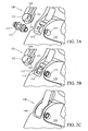
- FIGS 2A-2C illustrate detailed rear exploded perspective views of the lower shell coupler and lower shell in accordance with the embodiment illustrated in Figure 1 ;
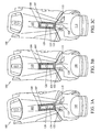
- Figures 3A-3C illustrate rear coronal rotational views of the lower shell coupler, lower shell, and upper shell in accordance with the embodiment illustrated in Figure 1 ;
- Figure 4A illustrates a perspective view of the upper shell, lower shell, upper shell coupler, and lower shell coupler in accordance with the embodiment illustrated in Figure 1 ;
- Figure 4B illustrates an exploded perspective view of the upper shell, upper shell coupler, and lean adjustment system in accordance with the embodiment illustrated in Figure 1 ;
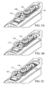
- Figures 5A-5C illustrate rear perspective views of the upper shell and upper shell coupler in various lean adjustment positions in accordance with the embodiment illustrated in Figure 1 ;
- Figures 6A-6C illustrate perspective views of the boot system in various lean adjustment positions in accordance with the embodiment illustrated in Figure 1 .
- the present invention relates to boot articulation systems that selectively affect the articulation freedom of user's foot within a boot.
- a ski boot system including an upper shell, lower shell, and an articulation system.
- the upper shell is encapsulated around a portion of the user's lower leg
- the lower shell is encapsulated around a user's foot.
- the upper and lower shells function to enable a user to move their encased foot in various dimensions/orientations corresponding to anatomical supination, pronation, dorsiflexion, and plantarflexion.
- the articulation system selectively affects the articulation freedom between the upper and lower shells in locked and unlocked configurations.
- the locked configuration of the articulation system corresponds to restricting a plurality of dimensional articulation freedom between the upper and lower shell.
- the articulation system includes a lower shell coupler and an upper shell coupler coupled to the lower and upper shells, respectively.
- the lower shell coupler may extend internally within the upper shell.
- the locked configuration of the articulation system includes engaging the upper and lower shell couplers to restrict freedom between the upper and lower shell.
- the lower shell coupler is coupled within a recess in the lower shell that substantially restricts movement to a single orientation corresponding to coronal rotation. Coronal rotation between the lower shell coupler and the lower shell corresponds to anatomical supination and pronation with respect to the manner in which a corresponding user's foot is oriented in the lower shell.
- the coupling between the lower shell coupler and the lower shell may enable more than one degree and less than five degrees of coronal rotational freedom in both the locked and unlocked configurations of the articulation system.
- Alternative embodiments may include incorporating a similar coupling between the upper shell and upper shell coupler that substantially restricts movement to coronal rotation.
- the upper shell coupler coupling to the upper shell may be used in conjunction with a lower shell coupler coupling or in the alternative.
- the articulation system may also include a switching mechanism that selectively switches between the locked and unlocked configuration.
- embodiments of the present invention are directed at selectable boot articulation systems, it will be appreciated that teachings of the present invention are applicable to other areas.
- Ski - Any type of skiing apparatus that allows a user to translate on a snow surface, including but not limited to cross country skis, alpine skis, powder skis, telemark skis, downhill skis, snowboards, splitboards, skiboards, etc.
- Ski Boot - A boot used for translating on a snow surface including but not limited to snow sport boots for any type of skiing, snowboarding, etc.
- Sagittal plane An anatomical plane oriented vertically so as to bisect the left and right portions of the body.
- the sagittal plane is used herein for orientation purposes with respect to a boot as it is related to a human foot and lower leg.
- a boot which is placed on a human foot is effectively oriented sagittally (parallel to the sagittal plane) in a profile perspective. Therefore, the bottom of the boot is sagittally below the top of the boot.
- the term "sagittally” may also refer to a position within the sagittal plane such as an elevation.
- Transverse plane An anatomical plane oriented horizontally so as to bisect the top and bottom portions of the body.
- the transverse plane is used herein for orientation purposes with respect to a boot as it is related to a human foot and lower leg.
- a boot which is placed on a human foot is oriented orthogonally to the transverse plane. Therefore, a transversely oriented member on the boot would extended horizontally or between the sides of the boot.
- the bottom surface of the boot may three dimensionally extend transversely.
- Coronal plane - An anatomical plane oriented vertically so as to bisect the front and rear portions of the body.
- the coronal plane is used herein for orientation purposes with respect to a boot as it is related to a human foot and lower leg. Therefore, the coronal plane vertically bisects a boot between the toe and the heel.
- the anatomical movements of supination and pronation are effectively coronal rotations of the foot about the ankle.
- corresponding movements of boot components such as shell portions may also be described in terms of movements corresponding to how a user's foot would move.
- Embodiments of the present invention relate to snow sport boot systems incorporating an articulation system that affect the freedom of movement of a user's foot within the boot system.
- the articulation system generally includes a locked configuration and an unlocked configuration which correspond to skiing and walking configurations respectively.
- the locked configuration generally restricts movement and supports the user's foot and lower leg for optimal ski performance characteristics.
- the unlocked configuration allows movement of the user's foot and lower leg for optimal walking and/or skinning performance and efficiency characteristics.
- FIG. 1 illustrates a sagittal cross-sectional view of an articulation system on a boot system, designated generally at 100.
- the illustrated view is located at the rear/heel region of the boot at the intersection between the lower and upper shell.
- the boot system 100 includes a lower shell 110, an upper shell 105, and an articulation system.
- the articulation system includes a lower shell coupler 120, an upper shell coupler 140, and a switching mechanism 150.
- the lower shell coupler 120 and upper shell coupler 140 are coupler to the lower and upper shell 110, 105 respectively.
- the lower shell coupler 120 includes an elongated upper member 124 that extends within a portion of the upper shell 105.
- the lower shell coupler 120 also includes a curved lower member 122 coupled within a recess 114 of the lower shell.
- the coupling between the curved lower member 122 within the recess 114 includes extending a transverse pin 112 through both the curved member 122 and the recess 114.
- the coupling substantially restricts movement between the lower shell coupler 120 and the lower shell 110 to a single orientation corresponding to coronal rotation, supination, and pronation.
- the coupling between the lower shell coupler 120 and the lower shell 110 will be further described and illustrated in more detail below.
- the lower shell coupler 120 also includes a switching recess 126 disposed on the elongated upper member 124.
- the switching recess 126 is utilized to provide a selective coupling between the upper and lower shell couplers 120, 140 via the selective engagement of the switching mechanism 150 for purposes of engaging the locked configuration of the articulation system.
- the upper shell coupler 140 includes an external plate member 142 and an internal plate member 144 sandwich coupled to the upper shell 105 via a plurality of couplers 146.
- the external plate member 142 is disposed on an external region of the upper shell 105 and the internal plate member 144 is aligned therewith and disposed on an internal region of the upper shell 105.
- the external plate member 142 and internal plate member 144 are coupled to one another through a channel in the upper shell 107.
- the upper shell 105 includes a ribbed region 109 across which the external plate member 142 is disposed. The ribbed region 109 prevents translational movement of the external plate member 142 with respect to the upper shell 105.
- the plurality of couplers 146 extend through the external plate member 142, upper shell 105, and the internal plate member 144 thereby creating the sandwich coupling between the upper shell coupler 140 and the upper shell 140.
- the plurality of couplers 146 may be any elongated couplers including but not limited to screws, pins, bolts, etc.
- the internal plate member 144 may include threaded recesses through which the plurality of couplers 146 extend.
- the coupling between the upper shell coupler 140 and the upper shell 105 will be further described and illustrated in more detail below.
- the upper shell coupler 140 further includes a housing 140 that provides a region within which the switching mechanism 150 may selectively couple the upper and lower shell couplers 140, 120 to engage the locked configuration.
- the switching mechanism 150 includes a toggle switch 154 and a pin 152 disposed within the housing 147 of the upper shell coupler 140. It will be appreciated that various switching mechanisms and operative switch positions may be utilized in accordance with embodiments of the present invention.
- the toggle switch 154 is a two-position 180 degree switch operatively coupled to the pin 152 such that a first position corresponds to the pin 152 being retracted and a second position corresponds to the pin 152 being extended.
- the pin 152 is illustrated in a retracted position that includes substantial containment within the housing 147.
- the extended position of the pin 152 corresponds to the pin 152 extending through the switching recess 126 of the lower shell coupler 120.
- the extended position of the pin 152 effectively rigidly couples the lower shell coupler 120 and the upper shell coupler 140 which thereby impedes sagittal and torsional translation between the upper and lower shell 105, 110 corresponding to the locked configuration.
- the coupling between the upper and lower shell couplers 140, 120 does not restrict all movement between the upper and lower shell 105, 110.
- the coupling between the lower shell coupler 120 and the lower shell 110 allows a restricted movement in the coronal rotation orientation. Therefore, even if the upper and lower shell couplers 140, 120 are intercoupled, the upper shell 105 will be able to articulate in a coronal rotation orientation as defined by the coupling between the curved lower member 122 and the recess 114.
- FIGS 2A-2C illustrate detailed rear exploded perspective views of the lower shell coupler 120 and lower shell 110.
- the curved lower member 122 is positioned within the recess 114 of the lower shell 110 to restrict movement to a single dimensional orientation.
- the curved lower member 122 includes two oppositely oriented convexly curved surfaces 123 (only one of which is visible) and two hooded regions 125 (only one of which is visible).
- the curved surfaces 123 are curved in a coronal rotational orientation consistent with the arrow 180 illustrated in Figure 2C .
- the curved surfaces 123 are also geometrically shaped to restrict the degree of rotation within particular parameters.
- the hooded regions 125 correspond with the curved surfaces 125 to restrict movement.
- the hooded regions 125 restrict the lower coupler 120 from rotating transversely within the recess 114 corresponding to a torsional type rotation.
- the lower shell 110 includes a transverse pin 112, two pin recesses 115, and two spacers 113.
- the transverse pin 112 may extend through the two pin recesses 115, the spacers 113, the lower shell coupler 120, and the lower shell 110 as illustrated to effectively maintain a movable coupling between the lower shell coupler 120 and the lower shell 110.
- the spacers 113 are disposed within the recess 114 of the lower shell 110 and on opposite sides of the lower curved member 122.
- the spacers 113 each include a concave curved surface facing inward corresponding to the curved surfaces 123 of the lower shell coupler 120.
- the spacers 113 and curved lower member 122 are shaped to tightly fit within the recess 114 as illustrated in Figure 2C .
- the illustrated coupling scheme between the lower shell coupler 120 and the lower shell 110 substantially restricts movement freedom between the lower shell coupler 120 and the lower shell 110 to coronal rotation (represented by arrow 180) corresponding to anatomical supination and pronation. It will be appreciated that a similar coupling that restricts movement to coronal rotation may be implemented between the upper shell coupler 140 and the upper shell 105 in accordance with alternative embodiments of the present invention.
- FIGS 3A-3C illustrate rear coronal rotational views of the lower shell coupler 120, lower shell 110, and upper shell 105.
- the upper shell coupler 140 has been removed from the illustrated boot systems 100.
- the coupling scheme between the lower shell coupler 120 and the lower shell 110 allow for coronal rotation between the lower shell coupler 120 and the lower shell 110.
- the elongated upper member 124 of the lower shell coupler 120 may be disposed within the channel 107 of the upper shell 105 thereby aligning the upper shell 105 with the elongated upper member 124 of the lower shell coupler 120.
- the elongated upper member 124 of the lower shell coupler 120 is further contained within the channel 107 of the upper shell 105 by the positioning of the upper shell coupler 140 (not shown) over the channel.
- the upper shell 105 is free to articulate or rotate to either side corresponding to supination and pronation of the user's foot.
- Figure 3A illustrates the upper shell 105 coronally rotating to the left with respect to the lower shell 110 in accordance with a pronation movement.
- Figure 3B illustrates a neutral positioning of the upper shell 105 with respect to the lower shell 110.
- Figure 3C illustrates the upper shell 105 coronally rotating to the right with respect to the lower shell 110 in accordance with a supination movement.
- the coupling of the upper shell coupler 140 (not shown) to the lower shell coupler 120 does not substantially affect the ability of the upper shell 105 to coronally rotate in the manner illustrated. Therefore, the upper shell 105 is able to coronally rotate in both the locked and unlocked configurations of the articulation system.
- Figures 4A-4B illustrate perspective views of the upper shell 105 and upper shell coupler 110.
- the upper shell coupler 140 is sandwich coupled to the upper shell 105 through the channel 107.
- Figure 4A specifically illustrates how the upper shell coupler 140 and upper shell 105 may sagittally rotate or lean with respect to the lower shell 110 and lower shell coupler 120.
- Figure 4B specifically illustrates the coupling scheme between the upper shell coupler 140 and the upper shell 105 including the sandwich coupling between the external plate member 142 and internal plate member 144 across the ribbed region 109 and within the channel 107 of the upper shell 105.
- the plurality of couplers 146 extend through the external plate member 142, upper shell 105, and the internal plate member 144.
- the internally oriented surface of the external plate member 142 may include a corresponding ribbed region (not visible) that interfaces with the ribbed region 109 of the upper shell 105 to prevent translation and allow adjustment.
- the housing 147 provides the structure for the switching mechanism 150 (not shown) that switches between the locked and unlocked configurations.
- FIGS 5A-5C illustrate rear perspective views of the upper shell 105 and upper shell coupler 140 in various adjusted coupling positions corresponding to a lean adjustment between the upper shell 105 and the lower shell 110 (not shown).
- the upper shell coupler 140 may be coupled at various translational positions on the upper shell 105 to adjust the sagittal position at which the upper shell 105 couples to the lower shell 110 in the locked configuration. Since the locked configuration corresponds to engaging the upper and lower shell couplers 140, 120, a translation of the upper shell coupler 140 with respect to the upper shell 105 will affect the sagittal position at which the locked configuration restricts movement between the upper shell 105 and lower shell 110.
- the lean This sagittal rotational positioning is commonly referred to as the lean because it corresponds to the dorsiflexion and plantarflexion articulation of the user's foot with respect to their lower leg.
- the plurality of couplers 146 may be loosened to enable the upper shell coupler 140 to translate within channel and adjust the lean angle.
- the plurality of couplers must be retightened to prevent inadvertent slippage after the lean angle adjustment is made.
- the ribbed region 109 of the upper shell 105 may geometrically engage with a corresponding ribbed surface on the internally oriented surface of the external plate member 142 so as to prevent movement when the plurality of couplers 146 are tightened, thereby engaging the sandwich coupling.
- Figures 6A-6C illustrate perspective views of the boot system in various lean adjustment positions in the locked configuration, designated generally at 100.
- the coupling between the upper shell coupler 140 and the upper shell 105 may be translationally adjusted to affect the lean angle (sagittal rotation) between the upper and lower shell 105, 110 in the locked configuration of the articulation system.
- Figure 6A illustrates the upper shell 105 sagittally rotating backward with respect to the lower shell 110 corresponding to plantarflexion of a user's foot.
- Figure 6B illustrates the upper shell 105 sagittally rotating forward with respect to the lower shell 110 corresponding to dorsiflexion of a user's foot.
- One non-illustrated alternative embodiment incorporates telescoping linkages rather than the type of upper and lower couplers 140, 120 illustrated in the embodiment described above.
- the telescoping linkages may similarly be moveably coupled to the upper and lower shell 105, 110 in a manner that restricts movement to coronal rotation between the upper and lower shell 105, 110.
- An alternative boot system incorporating the telescoping linkages may also be switched between a similar locked/unlocked configuration to selectively enable sagittal rotation between the upper and lower shells 105, 110.
- the coupling between the telescoping linkage and the upper and lower shells 105, 110 may be adjusted to select various default forward lean and coronal canting configurations.
Landscapes
- Health & Medical Sciences (AREA)
- General Health & Medical Sciences (AREA)
- Physical Education & Sports Medicine (AREA)
- Footwear And Its Accessory, Manufacturing Method And Apparatuses (AREA)
Description
- FIELD OF THE INVENTION
- The invention generally relates to a selectable boot articulation system. In particular, the invention relates to a system for selectable articulation configurations between components of a boot.
- BACKGROUND OF THE INVENTION
- A boot is a type of footwear that encases both the foot and a portion of the lower leg of a user. Boots are generally manufactured for a particular purpose or activity and therefore are designed to include characteristics consistent with the intended purpose. For example, a hiking boot is designed to support the ankle of a user while minimizing the overall weight. Likewise, a ski boot is designed to maximize a user's performance at a particular skiing activity.
- Boots generally include a shell, a compression system, and a sole. The shell and compression system operate to encase and support the foot and lower leg of a user. Various well-known shell and compression systems are utilized to allow users to insert and remove their feet in an open boot configuration and compress the shell around the foot in a closed boot configuration. The sole of a boot is disposed on the bottom surface of the shell. The sole is generally composed of a rubber or plastic material. The sole may consist of a single piece or multiple blocks. The stiffness and/or weight characteristics of the sole have an effect on the overall performance of the boot.
- Existing boot systems often include some form of articulation system coupling portions of the shell together to allow for selectable articulation to facilitate sufficient walking/skinning performance in addition to optimal skiing performance. These articulation systems are generally switchable between a locked configuration and an unlocked configuration. The locked configuration corresponds to supporting the shell components to facilitate optimal skiing characteristics. The unlocked configuration corresponds to enabling desired movement between the shell components to facilitate optimal walking and/or skinning. Unfortunately, these existing articulation systems often fail to properly provide support in the locked configuration and often cause undesirable vibrations due to the dimensional freedom necessary to provide the unlocked configuration.
- The generic document
FR 2 682 571 A1 - Therefore, there is a need in the industry for a boot articulation system that provides desired support characteristics in the locked configuration and provides the necessary articulation in the unlocked configuration.
- SUMMARY OF THE INVENTION
- The present invention relates to boot articulation systems that selectively affect the articulation freedom of user's foot within a boot. One embodiment of the present invention relates to a ski boot system including an upper shell, lower shell, and an articulation system. The upper shell is encapsulated around a portion of the user's lower leg, and the lower shell is encapsulated around a user's foot. The upper and lower shells function to enable a user to move their encased foot in various dimensions/orientations corresponding to anatomical supination, pronation, dorsiflexion, and plantarflexion. The articulation system selectively affects the articulation freedom between the upper and lower shells in locked and unlocked configurations. The locked configuration of the articulation system corresponds to restricting a plurality of dimensional articulation freedom between the upper and lower shell. The articulation system includes a lower shell coupler and an upper shell coupler coupled to the lower and upper shells, respectively. The lower shell coupler may extend internally within the upper shell. The locked configuration of the articulation system includes engaging the upper and lower shell couplers to restrict freedom between the upper and lower shell. The lower shell coupler is coupled within a recess in the lower shell that substantially restricts movement to a single orientation corresponding to coronal rotation. Coronal rotation between the lower shell coupler and the lower shell corresponds to anatomical supination and pronation with respect to the manner in which a corresponding user's foot is oriented in the lower shell. The coupling between the lower shell coupler and the lower shell may enable more than one degree and less than five degrees of coronal rotational freedom in both the locked and unlocked configurations of the articulation system. Alternative embodiments may include incorporating a similar coupling between the upper shell and upper shell coupler that substantially restricts movement to coronal rotation. The upper shell coupler coupling to the upper shell may be used in conjunction with a lower shell coupler coupling or in the alternative. The articulation system may also include a switching mechanism that selectively switches between the locked and unlocked configuration.
- Embodiments of the present invention represent a significant advance in the field of ski boot articulation systems. Conventional articulation systems utilize an intentional loose rigid coupling between the lower shell coupler and the lower shell to allow the necessary articulation freedom between the lower and upper shell. However, the loose coupling allows a plurality of undesirable movement orientations/dimensions between the lower shell and lower shell coupler. Therefore, in both a locked and unlocked configuration, the upper and lower shells are able to articulate in plurality of orientations due to the loose coupling between the lower shell coupler and the lower shell. Undesirable vibrations occur as a result of the plurality of movement orientations between the upper and lower shell in a locked configuration. Conventional articulation systems thereby fail to properly restrict movement between the lower shell coupler and the lower shell to a single orientation and rather allow a plurality of movements orientations commonly referred to as slop. Embodiments of the present invention substantially restrict movement between the lower shell coupler and the lower shell to a single orientation, thereby eliminating undesirable movements and/or vibrations between the upper and lower shell in the locked configuration of the articulation system.
- These and other features and advantages of the present invention will be set forth or will become more fully apparent in the description that follows and in the appended claims. The features and advantages may be realized and obtained by means of the instruments and combinations particularly pointed out in the appended claims. Furthermore, the features and advantages of the invention may be learned by the practice of the invention or will be obvious from the description, as set forth hereinafter.
- BRIEF DESCRIPTION OF THE DRAWINGS
- The following description of the invention can be understood in light of the Figures, which illustrate specific aspects of the invention and are a part of the specification. Together with the following description, the Figures demonstrate and explain the principles of the invention. The Figures presented in conjunction with this description are views of only particular-rather than complete-portions of the systems and methods of making and using the system according to the invention. In the Figures, the physical dimensions may be exaggerated for clarity.
-
Figure 1 illustrates a sagittal cross-sectional view of an articulation system on a boot system in accordance with one embodiment of the present invention; -
Figures 2A-2C illustrate detailed rear exploded perspective views of the lower shell coupler and lower shell in accordance with the embodiment illustrated inFigure 1 ; -
Figures 3A-3C illustrate rear coronal rotational views of the lower shell coupler, lower shell, and upper shell in accordance with the embodiment illustrated inFigure 1 ; -
Figure 4A illustrates a perspective view of the upper shell, lower shell, upper shell coupler, and lower shell coupler in accordance with the embodiment illustrated inFigure 1 ; -
Figure 4B illustrates an exploded perspective view of the upper shell, upper shell coupler, and lean adjustment system in accordance with the embodiment illustrated inFigure 1 ; -
Figures 5A-5C illustrate rear perspective views of the upper shell and upper shell coupler in various lean adjustment positions in accordance with the embodiment illustrated inFigure 1 ; and -
Figures 6A-6C illustrate perspective views of the boot system in various lean adjustment positions in accordance with the embodiment illustrated inFigure 1 . - DETAILED DESCRIPTION OF THE INVENTION
- The present invention relates to boot articulation systems that selectively affect the articulation freedom of user's foot within a boot. One embodiment of the present invention relates to a ski boot system including an upper shell, lower shell, and an articulation system. The upper shell is encapsulated around a portion of the user's lower leg, and the lower shell is encapsulated around a user's foot. The upper and lower shells function to enable a user to move their encased foot in various dimensions/orientations corresponding to anatomical supination, pronation, dorsiflexion, and plantarflexion. The articulation system selectively affects the articulation freedom between the upper and lower shells in locked and unlocked configurations. The locked configuration of the articulation system corresponds to restricting a plurality of dimensional articulation freedom between the upper and lower shell. The articulation system includes a lower shell coupler and an upper shell coupler coupled to the lower and upper shells, respectively. The lower shell coupler may extend internally within the upper shell. The locked configuration of the articulation system includes engaging the upper and lower shell couplers to restrict freedom between the upper and lower shell. The lower shell coupler is coupled within a recess in the lower shell that substantially restricts movement to a single orientation corresponding to coronal rotation. Coronal rotation between the lower shell coupler and the lower shell corresponds to anatomical supination and pronation with respect to the manner in which a corresponding user's foot is oriented in the lower shell. The coupling between the lower shell coupler and the lower shell may enable more than one degree and less than five degrees of coronal rotational freedom in both the locked and unlocked configurations of the articulation system. Alternative embodiments may include incorporating a similar coupling between the upper shell and upper shell coupler that substantially restricts movement to coronal rotation. The upper shell coupler coupling to the upper shell may be used in conjunction with a lower shell coupler coupling or in the alternative. The articulation system may also include a switching mechanism that selectively switches between the locked and unlocked configuration. Also while embodiments of the present invention are directed at selectable boot articulation systems, it will be appreciated that teachings of the present invention are applicable to other areas.
- The following terms are defined as follows:
- Ski - Any type of skiing apparatus that allows a user to translate on a snow surface, including but not limited to cross country skis, alpine skis, powder skis, telemark skis, downhill skis, snowboards, splitboards, skiboards, etc.
- Ski Boot - A boot used for translating on a snow surface including but not limited to snow sport boots for any type of skiing, snowboarding, etc.
- Sagittal plane - An anatomical plane oriented vertically so as to bisect the left and right portions of the body. The sagittal plane is used herein for orientation purposes with respect to a boot as it is related to a human foot and lower leg. A boot which is placed on a human foot is effectively oriented sagittally (parallel to the sagittal plane) in a profile perspective. Therefore, the bottom of the boot is sagittally below the top of the boot. The term "sagittally" may also refer to a position within the sagittal plane such as an elevation.
- Transverse plane - An anatomical plane oriented horizontally so as to bisect the top and bottom portions of the body. The transverse plane is used herein for orientation purposes with respect to a boot as it is related to a human foot and lower leg. A boot which is placed on a human foot is oriented orthogonally to the transverse plane. Therefore, a transversely oriented member on the boot would extended horizontally or between the sides of the boot. For example, the bottom surface of the boot may three dimensionally extend transversely.
- Coronal plane - An anatomical plane oriented vertically so as to bisect the front and rear portions of the body. The coronal plane is used herein for orientation purposes with respect to a boot as it is related to a human foot and lower leg. Therefore, the coronal plane vertically bisects a boot between the toe and the heel. The anatomical movements of supination and pronation are effectively coronal rotations of the foot about the ankle. Likewise, corresponding movements of boot components such as shell portions may also be described in terms of movements corresponding to how a user's foot would move.
- Supination and Pronation - Coronal movements of the foot about the ankle.
- Dorsiflexion and Plantarflexion -Sagittal movements of the foot about the ankle.
- Embodiments of the present invention relate to snow sport boot systems incorporating an articulation system that affect the freedom of movement of a user's foot within the boot system. The articulation system generally includes a locked configuration and an unlocked configuration which correspond to skiing and walking configurations respectively. The locked configuration generally restricts movement and supports the user's foot and lower leg for optimal ski performance characteristics. Likewise, the unlocked configuration allows movement of the user's foot and lower leg for optimal walking and/or skinning performance and efficiency characteristics. The discussion below relates to a single operational embodiment of a boot system and articulation system. This single embodiment is described and illustrated in detail to provide one example of a system that effectively restricts movement without introducing undesired movement orientations. It will be appreciated that numerous other embodiments have been contemplated and that nothing herein should be interpreted to limit the claims to the single embodiment discussed below.
- Reference is initially made to
Figure 1 , which illustrates a sagittal cross-sectional view of an articulation system on a boot system, designated generally at 100. The illustrated view is located at the rear/heel region of the boot at the intersection between the lower and upper shell. Theboot system 100 includes alower shell 110, anupper shell 105, and an articulation system. The articulation system includes alower shell coupler 120, anupper shell coupler 140, and aswitching mechanism 150. Thelower shell coupler 120 andupper shell coupler 140 are coupler to the lower andupper shell - The
lower shell coupler 120 includes an elongatedupper member 124 that extends within a portion of theupper shell 105. Thelower shell coupler 120 also includes a curvedlower member 122 coupled within arecess 114 of the lower shell. The coupling between the curvedlower member 122 within therecess 114 includes extending atransverse pin 112 through both thecurved member 122 and therecess 114. The coupling substantially restricts movement between thelower shell coupler 120 and thelower shell 110 to a single orientation corresponding to coronal rotation, supination, and pronation. The coupling between thelower shell coupler 120 and thelower shell 110 will be further described and illustrated in more detail below. Thelower shell coupler 120 also includes aswitching recess 126 disposed on the elongatedupper member 124. Theswitching recess 126 is utilized to provide a selective coupling between the upper andlower shell couplers switching mechanism 150 for purposes of engaging the locked configuration of the articulation system. - The
upper shell coupler 140 includes anexternal plate member 142 and aninternal plate member 144 sandwich coupled to theupper shell 105 via a plurality ofcouplers 146. Theexternal plate member 142 is disposed on an external region of theupper shell 105 and theinternal plate member 144 is aligned therewith and disposed on an internal region of theupper shell 105. Theexternal plate member 142 andinternal plate member 144 are coupled to one another through a channel in theupper shell 107. Theupper shell 105 includes aribbed region 109 across which theexternal plate member 142 is disposed. Theribbed region 109 prevents translational movement of theexternal plate member 142 with respect to theupper shell 105. The plurality ofcouplers 146 extend through theexternal plate member 142,upper shell 105, and theinternal plate member 144 thereby creating the sandwich coupling between theupper shell coupler 140 and theupper shell 140. The plurality ofcouplers 146 may be any elongated couplers including but not limited to screws, pins, bolts, etc. Theinternal plate member 144 may include threaded recesses through which the plurality ofcouplers 146 extend. The coupling between theupper shell coupler 140 and theupper shell 105 will be further described and illustrated in more detail below. Theupper shell coupler 140 further includes ahousing 140 that provides a region within which theswitching mechanism 150 may selectively couple the upper andlower shell couplers - The
switching mechanism 150 includes atoggle switch 154 and apin 152 disposed within thehousing 147 of theupper shell coupler 140. It will be appreciated that various switching mechanisms and operative switch positions may be utilized in accordance with embodiments of the present invention. Thetoggle switch 154 is a two-position 180 degree switch operatively coupled to thepin 152 such that a first position corresponds to thepin 152 being retracted and a second position corresponds to thepin 152 being extended. Thepin 152 is illustrated in a retracted position that includes substantial containment within thehousing 147. The extended position of thepin 152 corresponds to thepin 152 extending through theswitching recess 126 of thelower shell coupler 120. The extended position of thepin 152 effectively rigidly couples thelower shell coupler 120 and theupper shell coupler 140 which thereby impedes sagittal and torsional translation between the upper andlower shell lower shell couplers lower shell lower shell coupler 120 and thelower shell 110 allows a restricted movement in the coronal rotation orientation. Therefore, even if the upper andlower shell couplers upper shell 105 will be able to articulate in a coronal rotation orientation as defined by the coupling between the curvedlower member 122 and therecess 114. - Reference is next made to
Figures 2A-2C , which illustrate detailed rear exploded perspective views of thelower shell coupler 120 andlower shell 110. As described above, the curvedlower member 122 is positioned within therecess 114 of thelower shell 110 to restrict movement to a single dimensional orientation. The curvedlower member 122 includes two oppositely oriented convexly curved surfaces 123 (only one of which is visible) and two hooded regions 125 (only one of which is visible). Thecurved surfaces 123 are curved in a coronal rotational orientation consistent with thearrow 180 illustrated inFigure 2C . Thecurved surfaces 123 are also geometrically shaped to restrict the degree of rotation within particular parameters. Thehooded regions 125 correspond with thecurved surfaces 125 to restrict movement. For example, thehooded regions 125 restrict thelower coupler 120 from rotating transversely within therecess 114 corresponding to a torsional type rotation. Likewise, thelower shell 110 includes atransverse pin 112, twopin recesses 115, and twospacers 113. Thetransverse pin 112 may extend through the twopin recesses 115, thespacers 113, thelower shell coupler 120, and thelower shell 110 as illustrated to effectively maintain a movable coupling between thelower shell coupler 120 and thelower shell 110. Thespacers 113 are disposed within therecess 114 of thelower shell 110 and on opposite sides of the lowercurved member 122. Thespacers 113 each include a concave curved surface facing inward corresponding to thecurved surfaces 123 of thelower shell coupler 120. Thespacers 113 and curvedlower member 122 are shaped to tightly fit within therecess 114 as illustrated inFigure 2C . The illustrated coupling scheme between thelower shell coupler 120 and thelower shell 110 substantially restricts movement freedom between thelower shell coupler 120 and thelower shell 110 to coronal rotation (represented by arrow 180) corresponding to anatomical supination and pronation. It will be appreciated that a similar coupling that restricts movement to coronal rotation may be implemented between theupper shell coupler 140 and theupper shell 105 in accordance with alternative embodiments of the present invention. - Reference is next made to
Figures 3A-3C , which illustrate rear coronal rotational views of thelower shell coupler 120,lower shell 110, andupper shell 105. For explanatory purposes, theupper shell coupler 140 has been removed from the illustratedboot systems 100. As discussed above, the coupling scheme between thelower shell coupler 120 and thelower shell 110 allow for coronal rotation between thelower shell coupler 120 and thelower shell 110. In addition, the elongatedupper member 124 of thelower shell coupler 120 may be disposed within thechannel 107 of theupper shell 105 thereby aligning theupper shell 105 with the elongatedupper member 124 of thelower shell coupler 120. The elongatedupper member 124 of thelower shell coupler 120 is further contained within thechannel 107 of theupper shell 105 by the positioning of the upper shell coupler 140 (not shown) over the channel. Theupper shell 105 is free to articulate or rotate to either side corresponding to supination and pronation of the user's foot.Figure 3A illustrates theupper shell 105 coronally rotating to the left with respect to thelower shell 110 in accordance with a pronation movement.Figure 3B illustrates a neutral positioning of theupper shell 105 with respect to thelower shell 110.Figure 3C illustrates theupper shell 105 coronally rotating to the right with respect to thelower shell 110 in accordance with a supination movement. The coupling of the upper shell coupler 140 (not shown) to thelower shell coupler 120 does not substantially affect the ability of theupper shell 105 to coronally rotate in the manner illustrated. Therefore, theupper shell 105 is able to coronally rotate in both the locked and unlocked configurations of the articulation system. - Reference is next made to
Figures 4A-4B , which illustrate perspective views of theupper shell 105 andupper shell coupler 110. Theupper shell coupler 140 is sandwich coupled to theupper shell 105 through thechannel 107.Figure 4A specifically illustrates how theupper shell coupler 140 andupper shell 105 may sagittally rotate or lean with respect to thelower shell 110 andlower shell coupler 120.Figure 4B specifically illustrates the coupling scheme between theupper shell coupler 140 and theupper shell 105 including the sandwich coupling between theexternal plate member 142 andinternal plate member 144 across theribbed region 109 and within thechannel 107 of theupper shell 105. The plurality ofcouplers 146 extend through theexternal plate member 142,upper shell 105, and theinternal plate member 144. The internally oriented surface of theexternal plate member 142 may include a corresponding ribbed region (not visible) that interfaces with theribbed region 109 of theupper shell 105 to prevent translation and allow adjustment. Thehousing 147 provides the structure for the switching mechanism 150 (not shown) that switches between the locked and unlocked configurations. - Reference is next made to
Figures 5A-5C , which illustrate rear perspective views of theupper shell 105 andupper shell coupler 140 in various adjusted coupling positions corresponding to a lean adjustment between theupper shell 105 and the lower shell 110 (not shown). Theupper shell coupler 140 may be coupled at various translational positions on theupper shell 105 to adjust the sagittal position at which theupper shell 105 couples to thelower shell 110 in the locked configuration. Since the locked configuration corresponds to engaging the upper andlower shell couplers upper shell coupler 140 with respect to theupper shell 105 will affect the sagittal position at which the locked configuration restricts movement between theupper shell 105 andlower shell 110. This sagittal rotational positioning is commonly referred to as the lean because it corresponds to the dorsiflexion and plantarflexion articulation of the user's foot with respect to their lower leg. In operation, the plurality ofcouplers 146 may be loosened to enable theupper shell coupler 140 to translate within channel and adjust the lean angle. The plurality of couplers must be retightened to prevent inadvertent slippage after the lean angle adjustment is made. Theribbed region 109 of theupper shell 105 may geometrically engage with a corresponding ribbed surface on the internally oriented surface of theexternal plate member 142 so as to prevent movement when the plurality ofcouplers 146 are tightened, thereby engaging the sandwich coupling. - Reference is next made to
Figures 6A-6C , which illustrate perspective views of the boot system in various lean adjustment positions in the locked configuration, designated generally at 100. As described above, the coupling between theupper shell coupler 140 and theupper shell 105 may be translationally adjusted to affect the lean angle (sagittal rotation) between the upper andlower shell Figure 6A illustrates theupper shell 105 sagittally rotating backward with respect to thelower shell 110 corresponding to plantarflexion of a user's foot.Figure 6B illustrates theupper shell 105 sagittally rotating forward with respect to thelower shell 110 corresponding to dorsiflexion of a user's foot. - One non-illustrated alternative embodiment incorporates telescoping linkages rather than the type of upper and
lower couplers lower shell lower shell lower shells lower shells - Various other embodiments have been contemplated including combinations in whole or in part of the embodiments described above.
Claims (17)
- A ski boot system (100) comprising:an upper shell (105) configured to encase a portion of a user's lower leg;a lower shell (110) configured to encase a user's foot, wherein the lower shell is moveably coupled with the upper shell; andan articulation system (120, 140, 150) coupled to the upper and lower shell including a locked configucation and an unlocked configuration, wherein the locked configuration restricts movement between the upper and lower shell in a plurality of orientations, and wherein the unlocked configuration enables articulation freedom between the upper and lower shell in a plurality of orientations corresponding to anatomical supination, pronation, dorsiflexion, and plantarflexion between the upper and lower shell;wherein the articulation system includes an upper shell coupler (140) and a lower shell coupler (120) coupled to the upper and lower shell respectively, and wherein the locked configuration corresponds to an engagement between the upper shell coupler and the lower shell coupler, and wherein the lower shell coupler is coupled within a recess (114) of the lower shell so as to substantially restrict freedom between the lower shell coupler and the lower shell to coronal rotation corresponding to anatomical supination and pronation, characterized in that the recess of the lower shell is a three dimensional recess including a coronally oriented curvature corresponding to a supination and pronation mouvement between the lower shell coupler and the lower shell.
- The ski boot system of claim 1, wherein the coupling between the lower shell coupler and the lower shell includes extending a transverse pin (112) through the recess and the lower shell coupler.
- The ski boot system of claim 2, wherein the recess includes two spacers (113) disposed on the transverse pin and on opposite transverse sides of the lower shell coupler, and wherein the two spacers include opposite concave curvatures oriented toward the lower shell coupler, and wherein the lower shell coupler includes corresponding outward oriented convex curvatures (123).
- The ski boot system of claim 34, wherein the curvatures an the ferst spacer, second spacer, and lower shell coupler enable the lower shell coupler to coronally rotate about the transverse pin in a manner corresponding to supination and pronation.
- The ski boot system of claim 4, wherein the curvatures of the lower shell coupler are shaped to restrict the coronal rotation of the lower shell coupler to within five degrees in both coconal rotation directions corresponding to supination and pronation.
- The ski boot system of claim 4, wherein the lower shell coupler includes a hooded region (125) adjacent to the convex curvatures that restricts torsional movement between the lower shell coupler and the lower shell.
- The ski boot system of claim 4, wherein the shape of the lower shell coupler and the recess restrict movement between the lower shell coupler and the lower shell in all orientations other than coronal rotation corresponding to anatomical supination and pronation.
- The ski boot system of claim 4, wherein the shape of the lower shell coupler and the recess restrict torsional rotational movement between the lower shell coupler and the lower shell.
- The ski boot system of claim 1, wherein the articulation system includes a selectable switching mechanism (150) configured to selectably engage and release the coupling between the lower shell coupler and the upper shell coupler corresponding to the locked configuration and the unlocked configuration respectively.
- The ski boot system of claim 9, wherein the selectable switching mechanism includes a retractable pin (152) coupled to the to upper shell coupler and configured to selectably extend through a recess (126) in the lower shell coupler.
- The ski boot system of claim 10, wherein the retractable pin is moveably coupled with a toggle switch (154) such that a First position of the toggle switch corresponds to the pin being extended through the recess in the lower shell coupler and a second position of the toggle switch corresponds to the pin being retracted from the recess in the lower shell coupler.
- The ski boot system of claim 1, wherein the upper shell coupler includes a lean adjustment system configured to adjust the position at which the upper shell coupler engages with the lover shell coupler for the locked configuration, wherein the position corresponds to a forward or rearward lean angle in the locked configuration.
- The ski boot system of claim 11, wherein the lean adjustment system further includes a translationally adjustable sandwich coupling (142, 144) between the upper shell coupler and the upper shell.
- The ski boot system of claim 11, wherein the lean adjustment system enables an adjustment range between ten degrees of forward lean and ten degrees of rearward lean between the upper and lower shell in the locked configuration.
- The ski boot system of claim 1, wherein the lower shell coupler is disposed in part internally within the upper shell.
- The ski boot system of claim 1, wherein the upper shell coupler is externally disposed an the upper shell.
- The ski boot system of claim 1, wherein the locked and unlocked configurations enable more than one degree and less than five degrees of coronal rotational freedom between the upper and lower shell corresponding to supination and pronation.
Applications Claiming Priority (1)
| Application Number | Priority Date | Filing Date | Title |
|---|---|---|---|
| US98565407P | 2007-11-06 | 2007-11-06 |
Publications (2)
| Publication Number | Publication Date |
|---|---|
| EP2057911A1 EP2057911A1 (en) | 2009-05-13 |
| EP2057911B1 true EP2057911B1 (en) | 2013-01-09 |
Family
ID=40361454
Family Applications (1)
| Application Number | Title | Priority Date | Filing Date |
|---|---|---|---|
| EP08168473A Not-in-force EP2057911B1 (en) | 2007-11-06 | 2008-11-06 | Selectable Boot Articulation System |
Country Status (2)
| Country | Link |
|---|---|
| US (1) | US9155351B2 (en) |
| EP (1) | EP2057911B1 (en) |
Families Citing this family (2)
| Publication number | Priority date | Publication date | Assignee | Title |
|---|---|---|---|---|
| US9241532B2 (en) | 2012-01-04 | 2016-01-26 | K-2 Corporation | Ski/walk mechanism |
| US20130255102A1 (en) | 2012-04-02 | 2013-10-03 | Rayford Terrell | Supplemental removable stick on cleat for footwear |
Family Cites Families (24)
| Publication number | Priority date | Publication date | Assignee | Title |
|---|---|---|---|---|
| US3303584A (en) * | 1964-12-24 | 1967-02-14 | Rosemount Eng Co Ltd | Edging adjustment for ski boots |
| US3885329A (en) * | 1974-05-15 | 1975-05-27 | Scott Usa | Ski boot with cantable upper |
| IT8222429U1 (en) * | 1982-07-19 | 1984-01-19 | Calzaturificio Tecnica | SKI BOOT WITH ADJUSTABLE SIDE INCLINATION CUFF. |
| IT8236198U1 (en) * | 1982-12-07 | 1984-06-07 | Perini Sergio | Ski boots with a rigid shaft and adjustable lateral inclination to adapt to the user's leg |
| CH645002A5 (en) * | 1983-02-23 | 1984-09-14 | Raichle Sportschuh Ag | SKI BOOT. |
| JPS6125207A (en) | 1984-07-12 | 1986-02-04 | Fanuc Ltd | Setting system of tool coordinate system |
| IT8423030U1 (en) * | 1984-09-06 | 1986-03-06 | Nordica Spa | STRUCTURE OF A DEVICE FOR VARIING THE INCLINATION OF SKI BOOTS. |
| US4675917A (en) * | 1986-11-03 | 1987-06-30 | Valli Laila S | Undergarment with inclusive shoulder pads |
| FR2617380B1 (en) * | 1987-07-03 | 1990-01-05 | Salomon Sa | FOOTWEAR COMPRISING A DEVICE FOR ADJUSTING THE INCLINATION OF THE ROD HINGE AXIS ON THE HULL |
| US5086573A (en) * | 1988-09-19 | 1992-02-11 | Salomon S.A. | Wearing apparel having an energy consuming device |
| EP0406212A3 (en) | 1989-03-07 | 1991-01-16 | Wolfgang Aigner | Sportshoe |
| FR2682571B1 (en) | 1991-10-17 | 1994-01-21 | Salomon Sa | SKI SHOE COMPRISING MEANS FOR ADJUSTING THE CROSS-SECTIONAL AND LONGITUDINAL INCLINATION OF ITS UPPER. |
| IT228031Y1 (en) * | 1992-05-15 | 1998-02-05 | Calzaturificio Tecnica Spa | IMPROVED SIDE TILT REGULATOR |
| CA2089313A1 (en) * | 1993-02-11 | 1994-08-12 | Randy Jespersen | Boot binding system for a snowboard |
| FR2719197B1 (en) * | 1994-04-29 | 1996-07-12 | Salomon Sa | Sliding sport shoe. |
| JP2812912B2 (en) * | 1995-11-10 | 1998-10-22 | 株式会社シマノ | Snowboard boots |
| IT1288602B1 (en) * | 1996-04-04 | 1998-09-23 | Stylus Spa | FOOTWEAR STRUCTURE, PARTICULARLY FOR SKATING |
| IT1297290B1 (en) * | 1997-11-05 | 1999-09-01 | Tecnica Spa | IMPROVEMENT RELATING TO LOCKING DEVICES FOR SPORTS SHOES, IN PARTICULAR FOR SKI BOOTS. |
| KR100294723B1 (en) * | 1997-11-18 | 2001-09-17 | 시마노 요시조 | Snowboard Boots Back Support System |
| US6076287A (en) | 1998-04-29 | 2000-06-20 | Shimano Inc. | Stance-support attachment for freestyle snowboard boot |
| US6663118B1 (en) | 1998-12-02 | 2003-12-16 | Shimano, Inc. | Snowboard interface with an upper portion that translates and rotates relative to a lower portion |
| FR2847432B1 (en) * | 2002-11-27 | 2005-02-11 | Random Design | ASSEMBLY COMPRISING TWO ARTICULATED BOOTS HAVING DIFFERENT MECHANICAL CHARACTERISTICS |
| US7641215B2 (en) * | 2006-02-28 | 2010-01-05 | Matthew Wade Ellison | Ski and snowboard equipment system |
| AT503543B1 (en) * | 2006-07-18 | 2007-11-15 | Barthel Fritz | Sports shoe e.g. winter sports shoe, has coupling plate forming articulated connection between shaft parts through swivel joints, such that coupling plate and shaft parts in connection with spherical and swivel joints form four-joint |
-
2008
- 2008-11-02 US US12/263,480 patent/US9155351B2/en not_active Expired - Fee Related
- 2008-11-06 EP EP08168473A patent/EP2057911B1/en not_active Not-in-force
Also Published As
| Publication number | Publication date |
|---|---|
| US20090113764A1 (en) | 2009-05-07 |
| US9155351B2 (en) | 2015-10-13 |
| EP2057911A1 (en) | 2009-05-13 |
Similar Documents
| Publication | Publication Date | Title |
|---|---|---|
| EP2057912A1 (en) | Modular boot sole system | |
| US4839972A (en) | Footwear with pivotal toe | |
| US5815953A (en) | Downhill snow sport boot assembly | |
| US7444769B2 (en) | Boot binding interface system | |
| RU2607765C2 (en) | Shoes intended for winter sports or walking | |
| US7810258B2 (en) | Boot articulation support system | |
| FR2803987A1 (en) | Reinforcing and protecting cover for boot used e.g. in winter sports is hinged to rod passing through forward end of sole | |
| US4144659A (en) | Ski boot | |
| US20020088146A1 (en) | Composite ski boot | |
| US5400527A (en) | Biomechanical ski boot with resilient elements in the sole | |
| JPH07148002A (en) | Sport shoes | |
| US6446363B1 (en) | Alpine ski boots having a flexible upper | |
| WO1998047576A1 (en) | Flexible footbed skate | |
| US9155351B2 (en) | Selectable boot articulation system | |
| EP2250916A1 (en) | Modular boot sole system | |
| EP1852025A1 (en) | Improved ski boot | |
| EP3687330B1 (en) | Ski boot | |
| US6659493B1 (en) | Connector plate for bindings | |
| WO2009097550A1 (en) | Winter sports footwear device | |
| EP1010443B1 (en) | Snowboard interface with an upper portion that translates and rotates relative to a lower portion | |
| WO2000069980A2 (en) | Connector plate for bindings | |
| US7011333B2 (en) | Snowboard binding | |
| US8132344B2 (en) | Selectable boot support and articulation system | |
| US4758016A (en) | Device to fasten a cross-country ski boot on a cross-country ski | |
| US20250072552A1 (en) | Ski boot with rear lever part |
Legal Events
| Date | Code | Title | Description |
|---|---|---|---|
| PUAI | Public reference made under article 153(3) epc to a published international application that has entered the european phase |
Free format text: ORIGINAL CODE: 0009012 |
|
| AK | Designated contracting states |
Kind code of ref document: A1 Designated state(s): AT BE BG CH CY CZ DE DK EE ES FI FR GB GR HR HU IE IS IT LI LT LU LV MC MT NL NO PL PT RO SE SI SK TR |
|
| AX | Request for extension of the european patent |
Extension state: AL BA MK RS |
|
| 17P | Request for examination filed |
Effective date: 20091113 |
|
| AKX | Designation fees paid |
Designated state(s): AT BE BG CH CY CZ DE DK EE ES FI FR GB GR HR HU IE IS IT LI LT LU LV MC MT NL NO PL PT RO SE SI SK TR |
|
| 17Q | First examination report despatched |
Effective date: 20100119 |
|
| GRAP | Despatch of communication of intention to grant a patent |
Free format text: ORIGINAL CODE: EPIDOSNIGR1 |
|
| GRAS | Grant fee paid |
Free format text: ORIGINAL CODE: EPIDOSNIGR3 |
|
| GRAA | (expected) grant |
Free format text: ORIGINAL CODE: 0009210 |
|
| AK | Designated contracting states |
Kind code of ref document: B1 Designated state(s): AT BE BG CH CY CZ DE DK EE ES FI FR GB GR HR HU IE IS IT LI LT LU LV MC MT NL NO PL PT RO SE SI SK TR |
|
| REG | Reference to a national code |
Ref country code: GB Ref legal event code: FG4D |
|
| REG | Reference to a national code |
Ref country code: CH Ref legal event code: EP Ref country code: AT Ref legal event code: REF Ref document number: 592232 Country of ref document: AT Kind code of ref document: T Effective date: 20130115 |
|
| REG | Reference to a national code |
Ref country code: IE Ref legal event code: FG4D |
|
| REG | Reference to a national code |
Ref country code: DE Ref legal event code: R096 Ref document number: 602008021498 Country of ref document: DE Effective date: 20130314 |
|
| PG25 | Lapsed in a contracting state [announced via postgrant information from national office to epo] |
Ref country code: SI Free format text: LAPSE BECAUSE OF FAILURE TO SUBMIT A TRANSLATION OF THE DESCRIPTION OR TO PAY THE FEE WITHIN THE PRESCRIBED TIME-LIMIT Effective date: 20130109 |
|
| REG | Reference to a national code |
Ref country code: NL Ref legal event code: VDEP Effective date: 20130109 |
|
| REG | Reference to a national code |
Ref country code: AT Ref legal event code: MK05 Ref document number: 592232 Country of ref document: AT Kind code of ref document: T Effective date: 20130109 |
|
| REG | Reference to a national code |
Ref country code: LT Ref legal event code: MG4D |
|
| PG25 | Lapsed in a contracting state [announced via postgrant information from national office to epo] |
Ref country code: SE Free format text: LAPSE BECAUSE OF FAILURE TO SUBMIT A TRANSLATION OF THE DESCRIPTION OR TO PAY THE FEE WITHIN THE PRESCRIBED TIME-LIMIT Effective date: 20130109 Ref country code: IS Free format text: LAPSE BECAUSE OF FAILURE TO SUBMIT A TRANSLATION OF THE DESCRIPTION OR TO PAY THE FEE WITHIN THE PRESCRIBED TIME-LIMIT Effective date: 20130509 Ref country code: ES Free format text: LAPSE BECAUSE OF FAILURE TO SUBMIT A TRANSLATION OF THE DESCRIPTION OR TO PAY THE FEE WITHIN THE PRESCRIBED TIME-LIMIT Effective date: 20130420 Ref country code: BE Free format text: LAPSE BECAUSE OF FAILURE TO SUBMIT A TRANSLATION OF THE DESCRIPTION OR TO PAY THE FEE WITHIN THE PRESCRIBED TIME-LIMIT Effective date: 20130109 Ref country code: AT Free format text: LAPSE BECAUSE OF FAILURE TO SUBMIT A TRANSLATION OF THE DESCRIPTION OR TO PAY THE FEE WITHIN THE PRESCRIBED TIME-LIMIT Effective date: 20130109 Ref country code: NO Free format text: LAPSE BECAUSE OF FAILURE TO SUBMIT A TRANSLATION OF THE DESCRIPTION OR TO PAY THE FEE WITHIN THE PRESCRIBED TIME-LIMIT Effective date: 20130409 Ref country code: LT Free format text: LAPSE BECAUSE OF FAILURE TO SUBMIT A TRANSLATION OF THE DESCRIPTION OR TO PAY THE FEE WITHIN THE PRESCRIBED TIME-LIMIT Effective date: 20130109 Ref country code: BG Free format text: LAPSE BECAUSE OF FAILURE TO SUBMIT A TRANSLATION OF THE DESCRIPTION OR TO PAY THE FEE WITHIN THE PRESCRIBED TIME-LIMIT Effective date: 20130409 |
|
| PG25 | Lapsed in a contracting state [announced via postgrant information from national office to epo] |
Ref country code: NL Free format text: LAPSE BECAUSE OF FAILURE TO SUBMIT A TRANSLATION OF THE DESCRIPTION OR TO PAY THE FEE WITHIN THE PRESCRIBED TIME-LIMIT Effective date: 20130109 Ref country code: PL Free format text: LAPSE BECAUSE OF FAILURE TO SUBMIT A TRANSLATION OF THE DESCRIPTION OR TO PAY THE FEE WITHIN THE PRESCRIBED TIME-LIMIT Effective date: 20130109 Ref country code: LV Free format text: LAPSE BECAUSE OF FAILURE TO SUBMIT A TRANSLATION OF THE DESCRIPTION OR TO PAY THE FEE WITHIN THE PRESCRIBED TIME-LIMIT Effective date: 20130109 Ref country code: GR Free format text: LAPSE BECAUSE OF FAILURE TO SUBMIT A TRANSLATION OF THE DESCRIPTION OR TO PAY THE FEE WITHIN THE PRESCRIBED TIME-LIMIT Effective date: 20130410 Ref country code: PT Free format text: LAPSE BECAUSE OF FAILURE TO SUBMIT A TRANSLATION OF THE DESCRIPTION OR TO PAY THE FEE WITHIN THE PRESCRIBED TIME-LIMIT Effective date: 20130509 Ref country code: FI Free format text: LAPSE BECAUSE OF FAILURE TO SUBMIT A TRANSLATION OF THE DESCRIPTION OR TO PAY THE FEE WITHIN THE PRESCRIBED TIME-LIMIT Effective date: 20130109 |
|
| PG25 | Lapsed in a contracting state [announced via postgrant information from national office to epo] |
Ref country code: HR Free format text: LAPSE BECAUSE OF FAILURE TO SUBMIT A TRANSLATION OF THE DESCRIPTION OR TO PAY THE FEE WITHIN THE PRESCRIBED TIME-LIMIT Effective date: 20130109 |
|
| PG25 | Lapsed in a contracting state [announced via postgrant information from national office to epo] |
Ref country code: EE Free format text: LAPSE BECAUSE OF FAILURE TO SUBMIT A TRANSLATION OF THE DESCRIPTION OR TO PAY THE FEE WITHIN THE PRESCRIBED TIME-LIMIT Effective date: 20130109 Ref country code: DK Free format text: LAPSE BECAUSE OF FAILURE TO SUBMIT A TRANSLATION OF THE DESCRIPTION OR TO PAY THE FEE WITHIN THE PRESCRIBED TIME-LIMIT Effective date: 20130109 Ref country code: SK Free format text: LAPSE BECAUSE OF FAILURE TO SUBMIT A TRANSLATION OF THE DESCRIPTION OR TO PAY THE FEE WITHIN THE PRESCRIBED TIME-LIMIT Effective date: 20130109 Ref country code: CZ Free format text: LAPSE BECAUSE OF FAILURE TO SUBMIT A TRANSLATION OF THE DESCRIPTION OR TO PAY THE FEE WITHIN THE PRESCRIBED TIME-LIMIT Effective date: 20130109 Ref country code: RO Free format text: LAPSE BECAUSE OF FAILURE TO SUBMIT A TRANSLATION OF THE DESCRIPTION OR TO PAY THE FEE WITHIN THE PRESCRIBED TIME-LIMIT Effective date: 20130109 |
|
| PLBE | No opposition filed within time limit |
Free format text: ORIGINAL CODE: 0009261 |
|
| STAA | Information on the status of an ep patent application or granted ep patent |
Free format text: STATUS: NO OPPOSITION FILED WITHIN TIME LIMIT |
|
| PG25 | Lapsed in a contracting state [announced via postgrant information from national office to epo] |
Ref country code: CY Free format text: LAPSE BECAUSE OF FAILURE TO SUBMIT A TRANSLATION OF THE DESCRIPTION OR TO PAY THE FEE WITHIN THE PRESCRIBED TIME-LIMIT Effective date: 20130109 |
|
| 26N | No opposition filed |
Effective date: 20131010 |
|
| PG25 | Lapsed in a contracting state [announced via postgrant information from national office to epo] |
Ref country code: IT Free format text: LAPSE BECAUSE OF FAILURE TO SUBMIT A TRANSLATION OF THE DESCRIPTION OR TO PAY THE FEE WITHIN THE PRESCRIBED TIME-LIMIT Effective date: 20130109 |
|
| REG | Reference to a national code |
Ref country code: DE Ref legal event code: R097 Ref document number: 602008021498 Country of ref document: DE Effective date: 20131010 |
|
| REG | Reference to a national code |
Ref country code: CH Ref legal event code: PL |
|
| GBPC | Gb: european patent ceased through non-payment of renewal fee |
Effective date: 20131106 |
|
| PG25 | Lapsed in a contracting state [announced via postgrant information from national office to epo] |
Ref country code: LI Free format text: LAPSE BECAUSE OF NON-PAYMENT OF DUE FEES Effective date: 20131130 Ref country code: MC Free format text: LAPSE BECAUSE OF FAILURE TO SUBMIT A TRANSLATION OF THE DESCRIPTION OR TO PAY THE FEE WITHIN THE PRESCRIBED TIME-LIMIT Effective date: 20130109 Ref country code: CH Free format text: LAPSE BECAUSE OF NON-PAYMENT OF DUE FEES Effective date: 20131130 |
|
| REG | Reference to a national code |
Ref country code: FR Ref legal event code: ST Effective date: 20140731 |
|
| REG | Reference to a national code |
Ref country code: IE Ref legal event code: MM4A |
|
| PG25 | Lapsed in a contracting state [announced via postgrant information from national office to epo] |
Ref country code: DE Free format text: LAPSE BECAUSE OF NON-PAYMENT OF DUE FEES Effective date: 20140603 |
|
| REG | Reference to a national code |
Ref country code: DE Ref legal event code: R119 Ref document number: 602008021498 Country of ref document: DE Effective date: 20140603 |
|
| PG25 | Lapsed in a contracting state [announced via postgrant information from national office to epo] |
Ref country code: IE Free format text: LAPSE BECAUSE OF NON-PAYMENT OF DUE FEES Effective date: 20131106 |
|
| PG25 | Lapsed in a contracting state [announced via postgrant information from national office to epo] |
Ref country code: GB Free format text: LAPSE BECAUSE OF NON-PAYMENT OF DUE FEES Effective date: 20131106 Ref country code: FR Free format text: LAPSE BECAUSE OF NON-PAYMENT OF DUE FEES Effective date: 20131202 |
|
| PG25 | Lapsed in a contracting state [announced via postgrant information from national office to epo] |
Ref country code: TR Free format text: LAPSE BECAUSE OF FAILURE TO SUBMIT A TRANSLATION OF THE DESCRIPTION OR TO PAY THE FEE WITHIN THE PRESCRIBED TIME-LIMIT Effective date: 20130109 |
|
| PG25 | Lapsed in a contracting state [announced via postgrant information from national office to epo] |
Ref country code: LU Free format text: LAPSE BECAUSE OF NON-PAYMENT OF DUE FEES Effective date: 20131106 Ref country code: HU Free format text: LAPSE BECAUSE OF FAILURE TO SUBMIT A TRANSLATION OF THE DESCRIPTION OR TO PAY THE FEE WITHIN THE PRESCRIBED TIME-LIMIT; INVALID AB INITIO Effective date: 20081106 |
|
| PG25 | Lapsed in a contracting state [announced via postgrant information from national office to epo] |
Ref country code: MT Free format text: LAPSE BECAUSE OF FAILURE TO SUBMIT A TRANSLATION OF THE DESCRIPTION OR TO PAY THE FEE WITHIN THE PRESCRIBED TIME-LIMIT Effective date: 20130109 |