EP2057405B1 - Hydraulic/pneumatic charging valve with integrated pressure transducer - Google Patents
Hydraulic/pneumatic charging valve with integrated pressure transducer Download PDFInfo
- Publication number
- EP2057405B1 EP2057405B1 EP07800485.0A EP07800485A EP2057405B1 EP 2057405 B1 EP2057405 B1 EP 2057405B1 EP 07800485 A EP07800485 A EP 07800485A EP 2057405 B1 EP2057405 B1 EP 2057405B1
- Authority
- EP
- European Patent Office
- Prior art keywords
- pressure
- receptacle
- valve
- sensing device
- channel
- Prior art date
- Legal status (The legal status is an assumption and is not a legal conclusion. Google has not performed a legal analysis and makes no representation as to the accuracy of the status listed.)
- Not-in-force
Links
- 239000012530 fluid Substances 0.000 claims description 25
- 238000004891 communication Methods 0.000 claims description 17
- 238000000034 method Methods 0.000 claims description 5
- 238000005259 measurement Methods 0.000 claims description 4
- 230000008878 coupling Effects 0.000 claims 1
- 238000010168 coupling process Methods 0.000 claims 1
- 238000005859 coupling reaction Methods 0.000 claims 1
- 230000035939 shock Effects 0.000 description 10
- 238000009530 blood pressure measurement Methods 0.000 description 6
- 238000003754 machining Methods 0.000 description 6
- 230000013011 mating Effects 0.000 description 5
- 239000004593 Epoxy Substances 0.000 description 4
- 238000012986 modification Methods 0.000 description 4
- 230000004048 modification Effects 0.000 description 4
- 238000003466 welding Methods 0.000 description 4
- 238000011065 in-situ storage Methods 0.000 description 3
- 238000004382 potting Methods 0.000 description 3
- 239000006096 absorbing agent Substances 0.000 description 2
- 239000004020 conductor Substances 0.000 description 2
- 238000010276 construction Methods 0.000 description 2
- 238000013461 design Methods 0.000 description 2
- 238000010586 diagram Methods 0.000 description 2
- 238000005553 drilling Methods 0.000 description 2
- 238000009434 installation Methods 0.000 description 2
- 230000002452 interceptive effect Effects 0.000 description 2
- 238000012423 maintenance Methods 0.000 description 2
- 239000002184 metal Substances 0.000 description 2
- 238000000926 separation method Methods 0.000 description 2
- 238000005476 soldering Methods 0.000 description 2
- 229920004943 Delrin® Polymers 0.000 description 1
- 239000004696 Poly ether ether ketone Substances 0.000 description 1
- 230000009471 action Effects 0.000 description 1
- 239000000853 adhesive Substances 0.000 description 1
- 230000001070 adhesive effect Effects 0.000 description 1
- 230000004075 alteration Effects 0.000 description 1
- 238000013459 approach Methods 0.000 description 1
- JUPQTSLXMOCDHR-UHFFFAOYSA-N benzene-1,4-diol;bis(4-fluorophenyl)methanone Chemical compound OC1=CC=C(O)C=C1.C1=CC(F)=CC=C1C(=O)C1=CC=C(F)C=C1 JUPQTSLXMOCDHR-UHFFFAOYSA-N 0.000 description 1
- 238000009529 body temperature measurement Methods 0.000 description 1
- UQMRAFJOBWOFNS-UHFFFAOYSA-N butyl 2-(2,4-dichlorophenoxy)acetate Chemical compound CCCCOC(=O)COC1=CC=C(Cl)C=C1Cl UQMRAFJOBWOFNS-UHFFFAOYSA-N 0.000 description 1
- 230000008859 change Effects 0.000 description 1
- 150000001875 compounds Chemical class 0.000 description 1
- 239000000428 dust Substances 0.000 description 1
- 238000009413 insulation Methods 0.000 description 1
- 239000000463 material Substances 0.000 description 1
- 230000037361 pathway Effects 0.000 description 1
- 230000000737 periodic effect Effects 0.000 description 1
- 239000004033 plastic Substances 0.000 description 1
- 229920002530 polyetherether ketone Polymers 0.000 description 1
- 230000000717 retained effect Effects 0.000 description 1
- 238000009420 retrofitting Methods 0.000 description 1
- 229910001220 stainless steel Inorganic materials 0.000 description 1
- 239000010935 stainless steel Substances 0.000 description 1
- 238000006467 substitution reaction Methods 0.000 description 1
- 239000004636 vulcanized rubber Substances 0.000 description 1
Images



Classifications
-
- F—MECHANICAL ENGINEERING; LIGHTING; HEATING; WEAPONS; BLASTING
- F17—STORING OR DISTRIBUTING GASES OR LIQUIDS
- F17C—VESSELS FOR CONTAINING OR STORING COMPRESSED, LIQUEFIED OR SOLIDIFIED GASES; FIXED-CAPACITY GAS-HOLDERS; FILLING VESSELS WITH, OR DISCHARGING FROM VESSELS, COMPRESSED, LIQUEFIED, OR SOLIDIFIED GASES
- F17C13/00—Details of vessels or of the filling or discharging of vessels
- F17C13/04—Arrangement or mounting of valves
-
- F—MECHANICAL ENGINEERING; LIGHTING; HEATING; WEAPONS; BLASTING
- F16—ENGINEERING ELEMENTS AND UNITS; GENERAL MEASURES FOR PRODUCING AND MAINTAINING EFFECTIVE FUNCTIONING OF MACHINES OR INSTALLATIONS; THERMAL INSULATION IN GENERAL
- F16F—SPRINGS; SHOCK-ABSORBERS; MEANS FOR DAMPING VIBRATION
- F16F9/00—Springs, vibration-dampers, shock-absorbers, or similarly-constructed movement-dampers using a fluid or the equivalent as damping medium
- F16F9/32—Details
- F16F9/3264—Arrangements for indicating, e.g. fluid level; Arrangements for checking dampers
-
- F—MECHANICAL ENGINEERING; LIGHTING; HEATING; WEAPONS; BLASTING
- F16—ENGINEERING ELEMENTS AND UNITS; GENERAL MEASURES FOR PRODUCING AND MAINTAINING EFFECTIVE FUNCTIONING OF MACHINES OR INSTALLATIONS; THERMAL INSULATION IN GENERAL
- F16F—SPRINGS; SHOCK-ABSORBERS; MEANS FOR DAMPING VIBRATION
- F16F9/00—Springs, vibration-dampers, shock-absorbers, or similarly-constructed movement-dampers using a fluid or the equivalent as damping medium
- F16F9/32—Details
- F16F9/3292—Sensor arrangements
-
- F—MECHANICAL ENGINEERING; LIGHTING; HEATING; WEAPONS; BLASTING
- F16—ENGINEERING ELEMENTS AND UNITS; GENERAL MEASURES FOR PRODUCING AND MAINTAINING EFFECTIVE FUNCTIONING OF MACHINES OR INSTALLATIONS; THERMAL INSULATION IN GENERAL
- F16F—SPRINGS; SHOCK-ABSORBERS; MEANS FOR DAMPING VIBRATION
- F16F9/00—Springs, vibration-dampers, shock-absorbers, or similarly-constructed movement-dampers using a fluid or the equivalent as damping medium
- F16F9/32—Details
- F16F9/43—Filling or drainage arrangements, e.g. for supply of gas
-
- F—MECHANICAL ENGINEERING; LIGHTING; HEATING; WEAPONS; BLASTING
- F16—ENGINEERING ELEMENTS AND UNITS; GENERAL MEASURES FOR PRODUCING AND MAINTAINING EFFECTIVE FUNCTIONING OF MACHINES OR INSTALLATIONS; THERMAL INSULATION IN GENERAL
- F16F—SPRINGS; SHOCK-ABSORBERS; MEANS FOR DAMPING VIBRATION
- F16F2230/00—Purpose; Design features
- F16F2230/0047—Measuring, indicating
-
- F—MECHANICAL ENGINEERING; LIGHTING; HEATING; WEAPONS; BLASTING
- F16—ENGINEERING ELEMENTS AND UNITS; GENERAL MEASURES FOR PRODUCING AND MAINTAINING EFFECTIVE FUNCTIONING OF MACHINES OR INSTALLATIONS; THERMAL INSULATION IN GENERAL
- F16F—SPRINGS; SHOCK-ABSORBERS; MEANS FOR DAMPING VIBRATION
- F16F2230/00—Purpose; Design features
- F16F2230/06—Fluid filling or discharging
-
- F—MECHANICAL ENGINEERING; LIGHTING; HEATING; WEAPONS; BLASTING
- F16—ENGINEERING ELEMENTS AND UNITS; GENERAL MEASURES FOR PRODUCING AND MAINTAINING EFFECTIVE FUNCTIONING OF MACHINES OR INSTALLATIONS; THERMAL INSULATION IN GENERAL
- F16F—SPRINGS; SHOCK-ABSORBERS; MEANS FOR DAMPING VIBRATION
- F16F2230/00—Purpose; Design features
- F16F2230/08—Sensor arrangement
-
- F—MECHANICAL ENGINEERING; LIGHTING; HEATING; WEAPONS; BLASTING
- F16—ENGINEERING ELEMENTS AND UNITS; GENERAL MEASURES FOR PRODUCING AND MAINTAINING EFFECTIVE FUNCTIONING OF MACHINES OR INSTALLATIONS; THERMAL INSULATION IN GENERAL
- F16F—SPRINGS; SHOCK-ABSORBERS; MEANS FOR DAMPING VIBRATION
- F16F2230/00—Purpose; Design features
- F16F2230/24—Detecting or preventing malfunction, e.g. fail safe
-
- F—MECHANICAL ENGINEERING; LIGHTING; HEATING; WEAPONS; BLASTING
- F17—STORING OR DISTRIBUTING GASES OR LIQUIDS
- F17C—VESSELS FOR CONTAINING OR STORING COMPRESSED, LIQUEFIED OR SOLIDIFIED GASES; FIXED-CAPACITY GAS-HOLDERS; FILLING VESSELS WITH, OR DISCHARGING FROM VESSELS, COMPRESSED, LIQUEFIED, OR SOLIDIFIED GASES
- F17C2250/00—Accessories; Control means; Indicating, measuring or monitoring of parameters
- F17C2250/04—Indicating or measuring of parameters as input values
- F17C2250/0404—Parameters indicated or measured
- F17C2250/043—Pressure
-
- F—MECHANICAL ENGINEERING; LIGHTING; HEATING; WEAPONS; BLASTING
- F17—STORING OR DISTRIBUTING GASES OR LIQUIDS
- F17C—VESSELS FOR CONTAINING OR STORING COMPRESSED, LIQUEFIED OR SOLIDIFIED GASES; FIXED-CAPACITY GAS-HOLDERS; FILLING VESSELS WITH, OR DISCHARGING FROM VESSELS, COMPRESSED, LIQUEFIED, OR SOLIDIFIED GASES
- F17C2270/00—Applications
- F17C2270/01—Applications for fluid transport or storage
- F17C2270/0186—Applications for fluid transport or storage in the air or in space
- F17C2270/0189—Planes
-
- Y—GENERAL TAGGING OF NEW TECHNOLOGICAL DEVELOPMENTS; GENERAL TAGGING OF CROSS-SECTIONAL TECHNOLOGIES SPANNING OVER SEVERAL SECTIONS OF THE IPC; TECHNICAL SUBJECTS COVERED BY FORMER USPC CROSS-REFERENCE ART COLLECTIONS [XRACs] AND DIGESTS
- Y10—TECHNICAL SUBJECTS COVERED BY FORMER USPC
- Y10T—TECHNICAL SUBJECTS COVERED BY FORMER US CLASSIFICATION
- Y10T29/00—Metal working
- Y10T29/49—Method of mechanical manufacture
- Y10T29/49716—Converting
Definitions
- the present invention relates to aircraft landing systems and more particularly to a device for measuring the pressure inside a landing gear shock strut.
- This invention is particularly useful for retrofit applications where drilling a new hole or changing the volume of the shock strut by the addition of a normal pressure transducer is not acceptable.
- Shock strut pressure is measured during maintenance of landing gear and other pressure vessels to ensure proper performance.
- the physical geometry of these pressure vessels (such as landing gear shock absorbers) determine (along with fluid and gas volumes) the behaviour and performance of the vessel.
- Measuring the pressure of the gas within the shock absorber is a critical task that must be performed regularly to ensure safe operation of the aircraft. This is presently performed by attaching a gauge to the external port of the charging valve, then opening the valve. This action is suboptimal because it requires a manual operation to connect and read the system, and because it involves the opening and closing of the valve (with the attendant loss of a small amount of fluid or gas).
- a poppet charging valve conforming to MS28889-2/MIL-PRF-6164F.
- This valve allows the introduction or removal of fluid and gas from the pressure vessel.
- the present invention modifies this valve to include a pressure-sensing means and electrical contact means such that measurements may be made of the working fluid without interfering with the normal operation of the valve or significantly altering the volume within the pressure vessel.
- This modified valve can be retrofitted to any landing gear to allow pressure measurements to be made without altering the landing gear.
- a change in military standards from MS28889-2 to the newer performance based specification - MIL-PRF- 6164F allows the certification of a modified valve to act as a replacement for existing valves.
- US patent no. 6,357,469 discloses a vehicle wheel including a tire that is sealed to a rim.
- the tire is inflated with air to a desired pressure level via a valve assembly.
- the valve assembly includes a valve stem with an elongated body having a central bore extending longitudinally through the body.
- a pressure sensor is mounted within the bore to measure the air pressure within the tire.
- a ball and plunger valve member is engagable and disengagable with a valve seat formed within the bore.
- a central tire inflation system uses the pressure sensor to monitor the tire pressure for each wheel on the vehicle. When the pressure sensor measures an air pressure in the tire that is below a desired level the central tire inflation system inflates the tire with air until the desired pressure is achieved.
- US patent no. 5,987,980 discloses a tire valve element assembly comprising a pressure sensing and transponder arrangement.
- the arrangement is mounted on a short valve element so as to extend axially from the short valve element and is sized to slidably fit within and be removable from a valve stem of a tire.
- the tire valve element assembly is adapted to be connected via an electrically conducting receptacle within the stem, so as to be a direct substitution for an existing in situ valve element in the tire valve stem.
- the arrangement is in fluid contact with the interior of the tire to sense the pressure within the tire when the short valve element is in situ.
- the arrangement when in situ, is electrically connected to a conductive portion of the valve element via the receptacle to facilitate an antenna system for radio frequency communication with the arrangement.
- the design involves introducing a pressure sensitive element on one end of the valve and providing a route for the measurement wires to a connector that is mounted internally in the valve stem.
- the connector is configured in such a manner that it does not interfere with normal pressure charging apparatus, but a specially designed electrical connector can connect to the valve for determining the pressure either in flight or on the ground.
- the present invention provides a charging valve for use in a pressure vessel in an aircraft landing gear comprising a valve body having a first and second end and a channel extending therebetween, a pressure-sensing device received within the channel at the first end and operable to measure the pressure of the pressure vessel, and a receptacle received within the channel between the pressure-sensing device and the second end, the receptable operable to be in communication with the pressure-sensing device and configured to allow fluid to flow through the valve, and the receptacle also operable to be electrically connected to a measuring device at the second end for communicating a pressure reading from the pressure-sensing device to the measuring device,wherein the pressure-sensing device comprises at least one wire extending from one end in electrical contact with the receptacle.
- the present invention provides a charging valve for use in a pressure vessel in an aircraft landing gear comprising a valve body having a first and second end and a channel extending therebetween, a pressure reading means connected to the first end of the valve body for reading the pressure in the pressure vessel and a receptacle received within the channel between the pressure reading means and the second end and operable to be in communication with the pressure reading means and configured to allow fluid to flow through the valve.
- the present invention provides a method of modifying a charging valve having a main body including a channel therethrough, to include a pressure measuring device for use in a pressure vessel comprising the steps of (i) placing a pressure-sensing device within the channel at the end of the valve that is in communication with the pressure vessel to allow the pressure-sensing device to measure the pressure within the vessel; (ii) electrically connecting the pressure-sensing device to a receptacle to allow for communication therebetween and electrically connecting the receptacle to a measuring device for communicating a pressure reading from the pressure-sensing device to the measuring device, the receptacle being located within the channel of the valve at the opposite end of the pressure-sensing device from the measurement end and being operable to allow for fluid to flow through the valve.
- the pressure-sensing device may be a pressure transducer or may include a modification to the end of the valve to form a pressure sensitive diaphragm that is gauged.
- the present invention provides a retrofit kit for use in a charging valve used with a pressure vessel comprising a pressure-sensing device sized to be received within the channel of the valve at the first end and operable to measure the pressure of the pressure vessel and a receptacle sized to be received within the channel of the valve and operable to be in communication with the pressure-sensing device and configured to allow fluid to flow through the valve.
- the pressure-sensing device and receptacle are as described herein.
- the present invention provides a modified charging valve having a pressure sensitive element at one end and a connector or receptacle mounted within it.
- the receptacle is configured to determine pressure within the valve either in flight or on the ground with minimal interference with the normal pressure charging apparatus.
- the modified valve of the present invention utilises the structure of known valves used in the art and incorporates within it a pressure-sensing device and a receptacle or connector that allows for pressure measurements to be made as desired without interfering with the normal operation of the valve and with minimal alteration of the volume of the working fluid within the pressure vessel.
- Pressure vessels and charging valves are known in the art and therefore are not described in detail herein.
- the existing end of the valve can also be modified to form a pressure sensitive diaphragm and then be gauged.
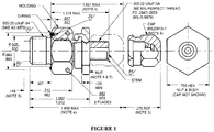
- Figure 1 provides a schematic diagram of the standard valve geometry.
- the present invention utilises the structure of valves known in the art.
- the valve is modified to accommodate, for example, the pressure-sensing device, the receptacle and a measuring device.
- Generally such known valves include a main body (also referred to as a valve stem herein), that has a central channel, or bore, that extends from one end of the body to the other.
- the present invention incorporates the use of a pressure-sensing device and receptacle within the channel of the body, as described below.
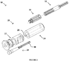
- FIG. 2 is an exploded perspective view illustrating the components of the modified valve, indicated in the Figures at numeral 18, which includes a valve stem 20 which is illustrated in two portions, a first portion 22 and a second portion 24.
- the modified valve 18 of the present invention may comprise one main body that does not consist of two separate parts, however in a preferred embodiment the valve main body comprises two portions to assist in the assembly of the modified valve.
- the description of the modified valve will make reference to a two part valve body, however a person skilled in the art will understand that a one part valve body may also be used.
- the stem 20 includes an elongate channel 26 that extends through the stem 20 from one end to the other, i.e. through the first and second portions 22, 24.
- the modified valve 18 also includes a pressure-sensing device 28 and a receptacle 30.
- the modified valve 18 may optionally include a plug 32 or the plug 32 may be a separate component that is used in combination with the modified valve 18 when a pressure reading is required, discussed in further detail below.
- the pressure-sensing device 28 may be any pressure-sensing device or transducer that is operable to measure pressure and is sized to be received within the first portion 22 of the stem 20.
- the channel 26 may be widened, for example by boring, to incorporate the pressure-sensing device 28.
- the pressure-sensing device 28 is fixedly attached to the end of the first portion 22 by any means known in the art, for example welding, using a laser or other means, fixed using an adhesive or mechanically retained within the channel 26.
- the connection of the pressure-sensing device 28 within the channel 26 may be by any means that allows the pressure-sensing device 28 to measure the pressure in the pressure vessel to which the valve 18 is attached.
- a pressure-sensing device 28 examples include, but is not limited to resistive strain gauges and capacitive gauges.
- the modified valve 18 of the present invention may also include a temperature sensitive element (not shown).
- Examples of the type of temperature sensitive elements that may be used include a thermocouple and a resistance temperature detector (RTD).
- the pressure sensing device 28 and the temperature sensing device may be an integrated piece operable to measure the pressure and temperature of the fluid within the pressure vessel. That is, the integrated pressure and temperature sensing device is preferably sized to be received within the first portion 22 of the valve stem 20. Alternatively, the channel 26 may be widened to receive the integrated pressure and temperature sensing device.
- the pressure-sensing device 28 includes a series of wires 38 extending from one end which allow the pressure measurement to be communicated to an external, or internal, measuring device or plug 32 via receptacle 30.
- the combined pressure and temperature measurements may be communicated to an external, or internal, measuring device or plug 32 via the receptacle 30.
- the receptacle 30 Located within the channel 26 in the second portion 24 of the stem 20 is the receptacle 30.
- the receptacle 30 is operable to be in communication with the pressure-sensing device 28 and is also operable to be electrically connected to a measuring device or plug 32 at the opposite end from the connection to the pressure-sensing device 28.
- the receptacle 30 is operable to communicate with the pressure-sensing device 28, and in the illustrated embodiment, the wires 38 of the pressure-sensing device 28 are connected to the receptacle 30.
- the connection of the wires 38 may be made by any means known in the art, including soldering.
- the receptacle 30 since the receptacle 30 is electrically connected to the pressure-sensing device 28 and the plug or measuring device 32, it facilitates communication of a pressure reading from the pressure sensing device 28 to the plug or measuring device 32.
- Figure 3 illustrates one embodiment of the receptacle 30, comprising a hollow cylindrical shell portion 40 within which a series of strips 42 are received.
- the strips 42 are connected to the interior surface of the shell portion 40 at spaced intervals.
- the strips 42 are attached to the shell portion 40 by any means known in the art that will withstand the environment of the valve and maintain the strips 42 in their position.
- the strips 42 are made from a conductive material and allow for communication between the wires 38 of the pressure-sensing device 28 and a measuring device or plug 32. As can be seen more clearly in Figure 8 , the strips 42 extend outwardly past the shell portion 40 in the direction of the pressure-sensing device 28.
- the wires 38 of the pressure-sensing device 28 are connected to the strips 42 by any means known in the art, for example soldering.
- the conductive material that is used is preferably inert to the fluid environment of the valve 18.
- the illustrated embodiment shows the receptacle 30 having four spaced strips 42 within it, however the number of strips and their size and configuration may vary provided that a conductive pathway is provided from the pressure-sensing device through the receptacle 30.
- the modified valve 18 allows for pressure measurements to be taken when desired with minimal interference with the valve operation and working fluid. Therefore, it will be understood that although variations to the number and positioning of the strips 42 may be made it is preferable to minimise the obstruction of the fluid through the receptacle 30.
- FIGS 3-7 alternative embodiments of the receptacle 30 are illustrated.
- Other variations of the receptacle 30 may be used to provide an electrical connection between the pressure-sensing device 28, and in particular the wires 38, and the plug or measuring device 32.
- the strips 42 are positioned on the receptacle 30 such as to provide sufficient separation therebetween so as to allow separation between the electrical connections on the strips 42.
- Figures 4 through 7 provide perspective drawings of other embodiments of the receptacle 30. In each of these figures it will be understood that the receptacle 30 is viewed from the end that is operable to connect to plug 32. The opposite end is connected to the wires 38 as described above.
- each of the illustrated receptacles 30 a series of apertures, indicated generally at 44, are shown that are operable to connect to the plug 32.
- the plug 32 will include protrusions, not shown, that will be sized and configured to be received within the apertures 44 to provide a connection there between.
- Figure 4 illustrates a receptacle 30 having a rectangular body with curved sides such as to be fittedly received within the channel 26. This involves machining grooves in the valve stem 20 (preferably the second portion 24) to accommodate the receptacle 30.
- the apertures 44 are located within the rectangular body in a parallel line. Each aperture 44 is sized to receive a conductive strip 42. Fluid is operable to flow on either side of the rectangle through the valve body.
- Figure 5 illustrates a circular or cylindrical embodiment of the receptacle 30 that includes a pair of locking tangs 46 for holding the connector 34 within the second portion 24 of the valve stem 20.
- the circular embodiment of the receptacle 30 is centrally located within the channel 26 and allows for fluid flow around the exterior circumference of the receptacle 30.
- Figure 6 illustrates a circular or cylindrical receptacle 30 that is suspended within the channel 26 by a cover 48.
- the cover 48 that extends around the connector 34 and is held within the valve shell 40 by a tab like attachment point, is preferably made from a thin metal to minimise interference with fluid flow around the connector and also to allow the minimum fluid flow rate in which the metal is susceptible to fatigue from twisting due to high fluid pressures.
- Figure 7 includes an alternate embodiment of the receptacle 30.
- the receptacle 30 is circular or cylindrical shaped and sized to fit within the channel 26.
- the illustrated circular receptacle 30 includes a hollow passageway therefore to allow for fluid flow.
- the apertures 44 are located within the walls of the receptacle 30.
- the plug 32 may form part of the valve 18 or may be a separate unit that is used only when required.
- the plug 32 is operable to connect with the receptacle 30 at the opposite end from the pressure-sensing device 28.
- the plug 32 includes a contact end that includes a series of connectors 52 having contact strips 54 that are operable to mate with the strips 42 on the receptacle 30.
- the connection, or mating, of these two components can be clearly seen in Figures 9A and 9B .
- the connection of the two parts allows for electrical contact between the pressure-sensing device 28, the receptacle 30 and the plug 32 and therefore allows a pressure reading to be taken and communicated to a user.
- connection point between the receptacle 30 and the plug 32 may be made by other means.
- a series of apertures 44 were provided for receiving protrusions on the plug 32 to allow for a connection between the pressure-sensing device, the receptacle 30 and the plug 32.
- Figure 10 provides an exploded perspective view of the embodiment of the plug described above, including contact strips 54 received in the connectors 52 sized to engage with the strips 42 on the receptacle 30.
- the contact strips 54 of the plug 32 and the strips 42 of the receptacle 30 may be slightly curved to ensure a secure lock between the components when mated.
- the insulation between each mating set of contact strips is the shell portion 40 of the receptacle 30 shown in Figure 9A .
- the shell portion 40 that mounts the conductive strips is preferably a dielectric plastic material such as Delrin or PEEK.
- the conductive strips are therefore mounted on an insulating mount, i.e. the shell portion, when located in the conductive stainless steel of the valve stem.
- the strips 42 and contact strips 54 may be offset radially as shown in Figure 10 to ensure that only one mating orientation works. Furthermore, one of the strips 42 of the receptacle 30 may be made deeper than the other strips to provide a mechanical guideway - the plug 32 would not fit into the hole in receptacle 30 unless rotated to the appropriate position.
- FIG. 11 An example of the machining requirements for one embodiment of the present invention is provided in Figure 11 . However, it will be understood that these are merely provided as an example and are not meant to be limiting in any way. The machining requirements may be changed depending on the valve size and the configuration of the connector and pressure sending device and plug to be utilised within the valve.
- the valve main body or stem 20 may be modified as follows: carve a 0.04" (0,10 cm) wide groove around the circumference of the stem 0.8" (2,0 cm) from the left and cut the stem in half at 0.84" (2,1 cm) starting from left of stem. As discussed above, this provides a two-part valve stem 20 that assists in the positioning and securing of the receptacle 30 to the wires 38 of the pressure-sensing device 28. However, this is not required and the receptacle 30 may be placed within the valve body/stem 20 while the stem 20 comprises one unitary piece.
- the first piece of the stem may be adapted to include a hole in the end facing the second stem piece with diameter 0.1170" offset (0.2971 cm) from centre with a depth of 0.6450" (1,6383 cm) using standard drill size 0.1142" (0,2901 cm) +0.004/-0.001 + 0,010/-0,003.
- a second hole at the opposite end may be drilled with diameter of 0.126" (0,320 cm) and a depth of 0.1750", (0,4445 cm) using standard drill size 0.1260" (0,3200 cm) +0.005/-0.001 (+0,013/-0,003 cm).
- the second half of the stem may be hollowed out to a diameter of 0.2000" (0,5080 cm) along the length of the piece. This could be done using a standard drill size 0.2008" +0.005/-0.001 (0,5100 cm +0,013/-0,003 cm).
- a cylindrical end piece 72 is machined with a diameter of 0.395" (1,003 cm) and length 0.180" (0,4572 cm) with an offset through hole with diameter 0.15", (0.381 cm) using a standard drill size 0.1496" +0.005/-0.001 (0,3800 +0,013/-0,003 cm) This hole would align with the hole through the first stem piece 22.
- the end piece 72 of the stem must be hermetically laser welded 62 onto the first half of the stem.
- the pressure-sensing device 28 is then put in place using the epoxy 58 near the lower portion of the transducer and potting 56 surrounding the head. This is to prevent residual stress caused by the epoxy curing from affecting the strain and pressure readings on the pressure-sensitive face of the transducer.
- the pressure-sensing device 28 should first be connected to the first portion 22 of the valve main body 20, as described above.
- the wires 38 from the pressure-sensing device 28, which protrude from the first portion of the main body 20 may be formed into one wire.
- the wires or wire may then be soldered onto the receptacle 30 (e.g. onto the strips 42).
- the receptacle 30 is then placed within the second portion 24 of the main body 20 and the first and second portions are connected together.
- the first and second portions (22, 24) are hermetically laser welded together.
- the modified valve 18 can then be reassembled with the unmodified valve housing 74 and locking nut 76 to make the valve functional.
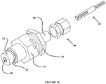
- the valve 18 may also include a cap 64, shown in Figure 15 .
- the cap 64 fits on the end of the second portion of the valve body and provides a dust cap or seal.
- the cap 64 may include the plug 32 which may be operable to be in communication with the receptacle 30 during the operation of the aircraft, i.e. pressure readings may be taken during operation of the aircraft whenever required.
- the cap 64 may be manually removed and the plug 32 be contained as a separate unit, for example a handheld unit, and connected to the receptacle 30 if and when a pressure reading is required.
- the present invention provides a modified valve according to the above description that includes a pressure-sensing means and a receptacle or connector that allows for periodic or continual communication with the pressure-sensing means.
- the present invention provides a method for retrofitting a valve within a pressure vessel to incorporate a pressure-sensing device within it.
- the present invention provides a pressure-sensing retrofit device that includes a connector that may be installed in a valve to allow for pressure measuring with minimal interference with the valve.
- the present invention provides a standard charging valve modified to add a pressure transducer with the active diaphragm subjected to the pressure within the charged vessel.
- the present invention further provides an arrangement to allow the wires and connector to not interfere with the flow of gas or oil so as to not interfere with normal servicing.
- the existing end of the valve may be modified to form a pressure sensitive diaphragm, which is then gauged.
- the gauges are indicated at numeral 70 and may be attached directly into the valve stem.
- Figure 16 illustrates the inclusion of a gauge 70 in the valve stem with wires 38 extending from the gauge.
- the wires are as described herein and may connect in a similar manner as described above.
- Figure 17 illustrates a further embodiment of the valve including the gauge in which the stem of the valve is modified to include a cavity that has been formed in one end of the valve.
- the cavity may be formed by machining and then welding the stem or by electro discharge machining (EDM).
- EDM electro discharge machining
- the strain gauge 70 may then be adhered in the cavity and the wires extend therefrom as described above. It will be understood that the gauge and wires may replace the pressure-sensing device described in the above embodiments.
Landscapes
- Engineering & Computer Science (AREA)
- General Engineering & Computer Science (AREA)
- Mechanical Engineering (AREA)
- Measuring Fluid Pressure (AREA)
- Indication Of The Valve Opening Or Closing Status (AREA)
- Fluid-Damping Devices (AREA)
- Force Measurement Appropriate To Specific Purposes (AREA)
Description
- The present invention relates to aircraft landing systems and more particularly to a device for measuring the pressure inside a landing gear shock strut. This invention is particularly useful for retrofit applications where drilling a new hole or changing the volume of the shock strut by the addition of a normal pressure transducer is not acceptable.
- Shock strut pressure is measured during maintenance of landing gear and other pressure vessels to ensure proper performance. The physical geometry of these pressure vessels (such as landing gear shock absorbers) determine (along with fluid and gas volumes) the behaviour and performance of the vessel. Measuring the pressure of the gas within the shock absorber is a critical task that must be performed regularly to ensure safe operation of the aircraft. This is presently performed by attaching a gauge to the external port of the charging valve, then opening the valve. This action is suboptimal because it requires a manual operation to connect and read the system, and because it involves the opening and closing of the valve (with the attendant loss of a small amount of fluid or gas).
- In order to reduce the amount of required maintenance, an automatic means of measuring the pressure of fluid within the shock strut is desired. Conventional approaches to this problem would involve the mounting of a pressure transducer either directly into the body of the shock strut, or the fitting of a manifold to the existing port to allow both a pressure measurement and a facility to charge (alter the quantity of fluid and gas). Both of these solutions present problems when they are applied to existing shock strut designs. Fitting a transducer into the body of the shock strut involves drilling a hole in the structure of the strut - which is generally not acceptable from a strength or fatigue perspective. Adding a manifold to the shock strut changes the amount of internal working volume, which changes the energy absorbing properties of the landing gear - which is not desirable.
- Many landing gears have a poppet charging valve conforming to MS28889-2/MIL-PRF-6164F. This valve allows the introduction or removal of fluid and gas from the pressure vessel. The present invention modifies this valve to include a pressure-sensing means and electrical contact means such that measurements may be made of the working fluid without interfering with the normal operation of the valve or significantly altering the volume within the pressure vessel.
- This modified valve can be retrofitted to any landing gear to allow pressure measurements to be made without altering the landing gear. A change in military standards from MS28889-2 to the newer performance based specification - MIL-PRF- 6164F allows the certification of a modified valve to act as a replacement for existing valves.
-
US patent no. 6,357,469 discloses a vehicle wheel including a tire that is sealed to a rim. The tire is inflated with air to a desired pressure level via a valve assembly. The valve assembly includes a valve stem with an elongated body having a central bore extending longitudinally through the body. A pressure sensor is mounted within the bore to measure the air pressure within the tire. A ball and plunger valve member is engagable and disengagable with a valve seat formed within the bore. A central tire inflation system uses the pressure sensor to monitor the tire pressure for each wheel on the vehicle. When the pressure sensor measures an air pressure in the tire that is below a desired level the central tire inflation system inflates the tire with air until the desired pressure is achieved. -
US patent no. 5,987,980 discloses a tire valve element assembly comprising a pressure sensing and transponder arrangement. The arrangement is mounted on a short valve element so as to extend axially from the short valve element and is sized to slidably fit within and be removable from a valve stem of a tire. The tire valve element assembly is adapted to be connected via an electrically conducting receptacle within the stem, so as to be a direct substitution for an existing in situ valve element in the tire valve stem. The arrangement is in fluid contact with the interior of the tire to sense the pressure within the tire when the short valve element is in situ. The arrangement, when in situ, is electrically connected to a conductive portion of the valve element via the receptacle to facilitate an antenna system for radio frequency communication with the arrangement. - At the base, the design involves introducing a pressure sensitive element on one end of the valve and providing a route for the measurement wires to a connector that is mounted internally in the valve stem. The connector is configured in such a manner that it does not interfere with normal pressure charging apparatus, but a specially designed electrical connector can connect to the valve for determining the pressure either in flight or on the ground.
- In one aspect the present invention provides a charging valve for use in a pressure vessel in an aircraft landing gear comprising a valve body having a first and second end and a channel extending therebetween, a pressure-sensing device received within the channel at the first end and operable to measure the pressure of the pressure vessel, and a receptacle received within the channel between the pressure-sensing device and the second end, the receptable operable to be in communication with the pressure-sensing device and configured to allow fluid to flow through the valve, and the receptacle also operable to be electrically connected to a measuring device at the second end for communicating a pressure reading from the pressure-sensing device to the measuring device,wherein the pressure-sensing device comprises at least one wire extending from one end in electrical contact with the receptacle.
- In another aspect the present invention provides a charging valve for use in a pressure vessel in an aircraft landing gear comprising a valve body having a first and second end and a channel extending therebetween, a pressure reading means connected to the first end of the valve body for reading the pressure in the pressure vessel and a receptacle received within the channel between the pressure reading means and the second end and
operable to be in communication with the pressure reading means and configured to allow fluid to flow through the valve. - In a further aspect the present invention provides a method of modifying a charging valve having a main body including a channel therethrough, to include a pressure measuring device for use in a pressure vessel comprising the steps of (i) placing a pressure-sensing device within the channel at the end of the valve that is in communication with the pressure vessel to allow the pressure-sensing device to measure the pressure within the vessel; (ii) electrically connecting the pressure-sensing device to a receptacle to allow for communication therebetween and electrically connecting the receptacle to a measuring device for communicating a pressure reading from the pressure-sensing device to the measuring device, the receptacle being located within the channel of the valve at the opposite end of the pressure-sensing device from the measurement end and being operable to allow for fluid to flow through the valve. The pressure-sensing device may be a pressure transducer or may include a modification to the end of the valve to form a pressure sensitive diaphragm that is gauged.
- In another aspect, the present invention provides a retrofit kit for use in a charging valve used with a pressure vessel comprising a pressure-sensing device sized to be received within the channel of the valve at the first end and operable to measure the pressure of the pressure vessel and a receptacle sized to be received within the channel of the valve and operable to be in communication with the pressure-sensing device and configured to allow fluid to flow through the valve. The pressure-sensing device and receptacle are as described herein.
- The present invention will now be described in further detail with reference to the following figures:
-
Figure 1 is a schematic diagram of the standard geometry of a charging valve; -
Figure 2 is an exploded perspective view showing the valve stem of the present invention in two portions and the pressure-sensing device, connector and plug to be used with the valve; -
Figure 3 is a perspective view of one embodiment of the receptacle of the present invention; -
Figure 4 is a perspective view of an alternate embodiment of the receptacle and the second portion of the modified valve stem of the present invention; -
Figure 5 is a perspective view of a further alternative embodiment of the receptacle and the second portion of the modified valve stem of the present invention; -
Figure 6 is a perspective view of a further embodiment of the receptacle of the valve of the present invention; -
Figure 7 is a perspective view of a further embodiment of the receptacle and the second part of the modified valve stem of the present invention; -
Figure 8 is a perspective exploded view of the receptacle and plug of the valve of the present invention according to the embodiment illustrated inFigure 3 ; -
Figures 9a is a perspective exploded view of the mating orientation of the receptacle and plug of the present invention; -
Figure 9b is a perspective view illustrating the mating connection of the plug and the receptacle ofFigure 9a ; -
Figure 10 is an exploded perspective view of one embodiment of the plug construction of the present invention; -
Figure 11 is a schematic showing the stem machining modifications for one embodiment of the valve of the present invention; -
Figure 12 is a side cross-sectional view of the placement and connection of the pressure-sensing device of the present invention; -
Figure 13 is a side cross-sectional view illustrating the welding of the pressure-sensing device during installation according to one embodiment; -
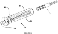
Figure 14 is an exploded perspective view illustrating the plug, and the assembly of the receptacle, the pressure-sensing device, and the valve stem according to one embodiment of the present invention; -
Figure 15 is a perspective view of one embodiment of the fully assembled valve of the present invention with the cap off; -
Figure 16 is a cross-sectional view of an alternative embodiment of the valve of the present invention wherein the valve is modified to form a pressure sensitive diaphragm that is gauged; and -
Figure 17 is a cross-sectional view of a further embodiment of the valve ofFigure 16 in which the valve stem has been modified to include a cavity in its end. - The present invention provides a modified charging valve having a pressure sensitive element at one end and a connector or receptacle mounted within it. The receptacle is configured to determine pressure within the valve either in flight or on the ground with minimal interference with the normal pressure charging apparatus.
- The modified valve of the present invention utilises the structure of known valves used in the art and incorporates within it a pressure-sensing device and a receptacle or connector that allows for pressure measurements to be made as desired without interfering with the normal operation of the valve and with minimal alteration of the volume of the working fluid within the pressure vessel. Pressure vessels and charging valves are known in the art and therefore are not described in detail herein. In an alternative embodiment, the existing end of the valve can also be modified to form a pressure sensitive diaphragm and then be gauged.
- The valve of the present invention will now be described in further detail with reference to the accompanying figures.
-
Figure 1 provides a schematic diagram of the standard valve geometry. As stated above, the present invention utilises the structure of valves known in the art. As will be described, the valve is modified to accommodate, for example, the pressure-sensing device, the receptacle and a measuring device. Generally such known valves include a main body (also referred to as a valve stem herein), that has a central channel, or bore, that extends from one end of the body to the other. The present invention incorporates the use of a pressure-sensing device and receptacle within the channel of the body, as described below. - Referring to
Figure 2 , one embodiment of the modified valve of the present invention will be described in further detail.Figure 2 is an exploded perspective view illustrating the components of the modified valve, indicated in the Figures atnumeral 18, which includes avalve stem 20 which is illustrated in two portions, afirst portion 22 and asecond portion 24. It will be understood that the modifiedvalve 18 of the present invention may comprise one main body that does not consist of two separate parts, however in a preferred embodiment the valve main body comprises two portions to assist in the assembly of the modified valve. The description of the modified valve will make reference to a two part valve body, however a person skilled in the art will understand that a one part valve body may also be used. Thestem 20 includes anelongate channel 26 that extends through thestem 20 from one end to the other, i.e. through the first andsecond portions - The modified
valve 18 also includes a pressure-sensingdevice 28 and areceptacle 30. The modifiedvalve 18 may optionally include aplug 32 or theplug 32 may be a separate component that is used in combination with the modifiedvalve 18 when a pressure reading is required, discussed in further detail below. - The pressure-sensing
device 28 may be any pressure-sensing device or transducer that is operable to measure pressure and is sized to be received within thefirst portion 22 of thestem 20. In an alternative embodiment, thechannel 26 may be widened, for example by boring, to incorporate the pressure-sensingdevice 28. The pressure-sensingdevice 28 is fixedly attached to the end of thefirst portion 22 by any means known in the art, for example welding, using a laser or other means, fixed using an adhesive or mechanically retained within thechannel 26. The connection of the pressure-sensingdevice 28 within thechannel 26 may be by any means that allows the pressure-sensingdevice 28 to measure the pressure in the pressure vessel to which thevalve 18 is attached. - Examples of the type of a pressure-sensing
device 28 that may be used include, but is not limited to resistive strain gauges and capacitive gauges. The modifiedvalve 18 of the present invention may also include a temperature sensitive element (not shown). Examples of the type of temperature sensitive elements that may be used include a thermocouple and a resistance temperature detector (RTD). As will be understood by a person skilled in the art, thepressure sensing device 28 and the temperature sensing device may be an integrated piece operable to measure the pressure and temperature of the fluid within the pressure vessel. That is, the integrated pressure and temperature sensing device is preferably sized to be received within thefirst portion 22 of thevalve stem 20. Alternatively, thechannel 26 may be widened to receive the integrated pressure and temperature sensing device. - In the illustrated embodiment of
Figure 2 , the pressure-sensingdevice 28 includes a series ofwires 38 extending from one end which allow the pressure measurement to be communicated to an external, or internal, measuring device or plug 32 viareceptacle 30. As will be understood, if an integrated temperature and pressure sensing device are used, the combined pressure and temperature measurements may be communicated to an external, or internal, measuring device or plug 32 via thereceptacle 30. - Located within the
channel 26 in thesecond portion 24 of thestem 20 is thereceptacle 30. Thereceptacle 30 is operable to be in communication with the pressure-sensingdevice 28 and is also operable to be electrically connected to a measuring device or plug 32 at the opposite end from the connection to the pressure-sensingdevice 28. Thereceptacle 30 is operable to communicate with the pressure-sensingdevice 28, and in the illustrated embodiment, thewires 38 of the pressure-sensingdevice 28 are connected to thereceptacle 30. The connection of thewires 38 may be made by any means known in the art, including soldering. Thus, since thereceptacle 30 is electrically connected to the pressure-sensingdevice 28 and the plug or measuringdevice 32, it facilitates communication of a pressure reading from thepressure sensing device 28 to the plug or measuringdevice 32. -
Figure 3 illustrates one embodiment of thereceptacle 30, comprising a hollowcylindrical shell portion 40 within which a series ofstrips 42 are received. Thestrips 42 are connected to the interior surface of theshell portion 40 at spaced intervals. Thestrips 42 are attached to theshell portion 40 by any means known in the art that will withstand the environment of the valve and maintain thestrips 42 in their position. Thestrips 42 are made from a conductive material and allow for communication between thewires 38 of the pressure-sensingdevice 28 and a measuring device or plug 32. As can be seen more clearly inFigure 8 , thestrips 42 extend outwardly past theshell portion 40 in the direction of the pressure-sensingdevice 28. Thewires 38 of the pressure-sensingdevice 28 are connected to thestrips 42 by any means known in the art, for example soldering. - The conductive material that is used is preferably inert to the fluid environment of the
valve 18. The illustrated embodiment shows thereceptacle 30 having four spacedstrips 42 within it, however the number of strips and their size and configuration may vary provided that a conductive pathway is provided from the pressure-sensing device through thereceptacle 30. - As stated above, the modified
valve 18 allows for pressure measurements to be taken when desired with minimal interference with the valve operation and working fluid. Therefore, it will be understood that although variations to the number and positioning of thestrips 42 may be made it is preferable to minimise the obstruction of the fluid through thereceptacle 30. - Referring to
Figures 3-7 , alternative embodiments of thereceptacle 30 are illustrated. Other variations of thereceptacle 30 may be used to provide an electrical connection between the pressure-sensingdevice 28, and in particular thewires 38, and the plug or measuringdevice 32. As will be understood referring toFigures 3-7 , that thestrips 42 are positioned on thereceptacle 30 such as to provide sufficient separation therebetween so as to allow separation between the electrical connections on thestrips 42.Figures 4 through 7 provide perspective drawings of other embodiments of thereceptacle 30. In each of these figures it will be understood that thereceptacle 30 is viewed from the end that is operable to connect to plug 32. The opposite end is connected to thewires 38 as described above. - Referring to
Figures 4 to 7 , at the end of each of the illustrated receptacles 30 a series of apertures, indicated generally at 44, are shown that are operable to connect to theplug 32. In these embodiments, theplug 32 will include protrusions, not shown, that will be sized and configured to be received within theapertures 44 to provide a connection there between. - Each alternative embodiment of the
receptacle 30 will now be described in more detail.Figure 4 illustrates areceptacle 30 having a rectangular body with curved sides such as to be fittedly received within thechannel 26. This involves machining grooves in the valve stem 20 (preferably the second portion 24) to accommodate thereceptacle 30. In this embodiment illustrated, theapertures 44 are located within the rectangular body in a parallel line. Eachaperture 44 is sized to receive aconductive strip 42. Fluid is operable to flow on either side of the rectangle through the valve body. -
Figure 5 illustrates a circular or cylindrical embodiment of thereceptacle 30 that includes a pair of lockingtangs 46 for holding the connector 34 within thesecond portion 24 of thevalve stem 20. The circular embodiment of thereceptacle 30 is centrally located within thechannel 26 and allows for fluid flow around the exterior circumference of thereceptacle 30. -
Figure 6 illustrates a circular orcylindrical receptacle 30 that is suspended within thechannel 26 by acover 48. It will be understood that in this embodiment thecover 48, that extends around the connector 34 and is held within thevalve shell 40 by a tab like attachment point, is preferably made from a thin metal to minimise interference with fluid flow around the connector and also to allow the minimum fluid flow rate in which the metal is susceptible to fatigue from twisting due to high fluid pressures. -
Figure 7 includes an alternate embodiment of thereceptacle 30. According to the embodiment illustrated, thereceptacle 30 is circular or cylindrical shaped and sized to fit within thechannel 26. The illustratedcircular receptacle 30 includes a hollow passageway therefore to allow for fluid flow. Theapertures 44 are located within the walls of thereceptacle 30. - The
plug 32 and its use will now be described in further detail. As stated above, theplug 32 may form part of thevalve 18 or may be a separate unit that is used only when required. Theplug 32 is operable to connect with thereceptacle 30 at the opposite end from the pressure-sensingdevice 28. In the illustrated embodiment, as can be seen inFigure 8 , theplug 32 includes a contact end that includes a series ofconnectors 52 having contact strips 54 that are operable to mate with thestrips 42 on thereceptacle 30. The connection, or mating, of these two components can be clearly seen inFigures 9A and 9B . The connection of the two parts allows for electrical contact between the pressure-sensingdevice 28, thereceptacle 30 and theplug 32 and therefore allows a pressure reading to be taken and communicated to a user. - It will be understood that the connection point between the
receptacle 30 and theplug 32 may be made by other means. For example, and as described above, in the alternative embodiments of the receptacle 30 a series ofapertures 44 were provided for receiving protrusions on theplug 32 to allow for a connection between the pressure-sensing device, thereceptacle 30 and theplug 32. -
Figure 10 provides an exploded perspective view of the embodiment of the plug described above, including contact strips 54 received in theconnectors 52 sized to engage with thestrips 42 on thereceptacle 30. - As can be seen in
Figures 9A and 9B the contact strips 54 of theplug 32 and thestrips 42 of thereceptacle 30 may be slightly curved to ensure a secure lock between the components when mated. The insulation between each mating set of contact strips is theshell portion 40 of thereceptacle 30 shown inFigure 9A . Theshell portion 40 that mounts the conductive strips is preferably a dielectric plastic material such as Delrin or PEEK. The conductive strips are therefore mounted on an insulating mount, i.e. the shell portion, when located in the conductive stainless steel of the valve stem. - To ensure that the
plug 32 andreceptacle 30 mate in the appropriate orientation (to ensure that the correct electrical connections are made), thestrips 42 and contact strips 54 may be offset radially as shown inFigure 10 to ensure that only one mating orientation works. Furthermore, one of thestrips 42 of thereceptacle 30 may be made deeper than the other strips to provide a mechanical guideway - theplug 32 would not fit into the hole inreceptacle 30 unless rotated to the appropriate position. - An example of the machining requirements for one embodiment of the present invention is provided in
Figure 11 . However, it will be understood that these are merely provided as an example and are not meant to be limiting in any way. The machining requirements may be changed depending on the valve size and the configuration of the connector and pressure sending device and plug to be utilised within the valve. - The valve main body or stem 20 may be modified as follows: carve a 0.04" (0,10 cm) wide groove around the circumference of the stem 0.8" (2,0 cm) from the left and cut the stem in half at 0.84" (2,1 cm) starting from left of stem. As discussed above, this provides a two-part valve stem 20 that assists in the positioning and securing of the
receptacle 30 to thewires 38 of the pressure-sensingdevice 28. However, this is not required and thereceptacle 30 may be placed within the valve body/stem 20 while thestem 20 comprises one unitary piece. - Once the
valve stem 20 has been divided into two pieces the first piece of the stem may be adapted to include a hole in the end facing the second stem piece with diameter 0.1170" offset (0.2971 cm) from centre with a depth of 0.6450" (1,6383 cm) using standard drill size 0.1142" (0,2901 cm) +0.004/-0.001 + 0,010/-0,003. A second hole at the opposite end (where the pressure-sensitive face of the transducer will be) may be drilled with diameter of 0.126" (0,320 cm) and a depth of 0.1750", (0,4445 cm) using standard drill size 0.1260" (0,3200 cm) +0.005/-0.001 (+0,013/-0,003 cm). - The second half of the stem may be hollowed out to a diameter of 0.2000" (0,5080 cm) along the length of the piece. This could be done using a standard drill size 0.2008" +0.005/-0.001 (0,5100 cm +0,013/-0,003 cm).
- In addition a
cylindrical end piece 72 is machined with a diameter of 0.395" (1,003 cm) and length 0.180" (0,4572 cm) with an offset through hole with diameter 0.15", (0.381 cm) using a standard drill size 0.1496" +0.005/-0.001 (0,3800 +0,013/-0,003 cm) This hole would align with the hole through thefirst stem piece 22. - The installation of the pressure-sensing
device 28 will now be described with reference toFigures 12 and13 . - In the illustrated embodiment, there were two methods that may be used to secure the pressure transducer or
pressure sensing device 28 in place. Either: (i) Using RoomTemperature Vulcanized rubber 56 potting compound &epoxy 58, shown inFigure 12 or (ii) micro laser welding 60 it in place, shown inFigure 13 . - When following the method illustrated in
Figure 12 , i.e.RTV 56 potting andepoxy 58, theend piece 72 of the stem must be hermetically laser welded 62 onto the first half of the stem. The pressure-sensingdevice 28 is then put in place using the epoxy 58 near the lower portion of the transducer and potting 56 surrounding the head. This is to prevent residual stress caused by the epoxy curing from affecting the strain and pressure readings on the pressure-sensitive face of the transducer. - If using a laser weld, as illustrated in
Figure 13 , to install the pressure-sensing device, insert thetransducer 28 into theend piece 72 until the pressure-sensitive face is flush with the surface of the end piece. Thenweld 60 the two parts together around the circumference of the transducer over the existing weld left from the construction of the transducer where it protrudes from the other side of the end piece. Place the assembled end piece and transducer at the end of the first stem piece with the transducer wires extending through the stem hole.Weld 62 theend piece 72 to thefirst stem piece 22 around the circumference where the two parts meet. - The assembly of the modified
valve 18 of the present invention will now be described with reference toFigures 14 and15 . - To assemble the system, the pressure-sensing
device 28 should first be connected to thefirst portion 22 of the valvemain body 20, as described above. Thewires 38 from the pressure-sensingdevice 28, which protrude from the first portion of themain body 20 may be formed into one wire. The wires or wire, may then be soldered onto the receptacle 30 (e.g. onto the strips 42). Thereceptacle 30 is then placed within thesecond portion 24 of themain body 20 and the first and second portions are connected together. Preferably the first and second portions (22, 24) are hermetically laser welded together. The modifiedvalve 18 can then be reassembled with theunmodified valve housing 74 and lockingnut 76 to make the valve functional. - The
valve 18 may also include acap 64, shown inFigure 15 . Thecap 64 fits on the end of the second portion of the valve body and provides a dust cap or seal. In one embodiment, thecap 64 may include theplug 32 which may be operable to be in communication with thereceptacle 30 during the operation of the aircraft, i.e. pressure readings may be taken during operation of the aircraft whenever required. Alternatively, thecap 64 may be manually removed and theplug 32 be contained as a separate unit, for example a handheld unit, and connected to thereceptacle 30 if and when a pressure reading is required. - The present invention provides a modified valve according to the above description that includes a pressure-sensing means and a receptacle or connector that allows for periodic or continual communication with the pressure-sensing means. In another aspect the present invention provides a method for retrofitting a valve within a pressure vessel to incorporate a pressure-sensing device within it. In a further aspect the present invention provides a pressure-sensing retrofit device that includes a connector that may be installed in a valve to allow for pressure measuring with minimal interference with the valve.
- The present invention provides a standard charging valve modified to add a pressure transducer with the active diaphragm subjected to the pressure within the charged vessel. The present invention further provides an arrangement to allow the wires and connector to not interfere with the flow of gas or oil so as to not interfere with normal servicing.
- In a further embodiment of the present invention the existing end of the valve may be modified to form a pressure sensitive diaphragm, which is then gauged. The gauges are indicated at
numeral 70 and may be attached directly into the valve stem.Figure 16 illustrates the inclusion of agauge 70 in the valve stem withwires 38 extending from the gauge. The wires are as described herein and may connect in a similar manner as described above. -
Figure 17 illustrates a further embodiment of the valve including the gauge in which the stem of the valve is modified to include a cavity that has been formed in one end of the valve. The cavity may be formed by machining and then welding the stem or by electro discharge machining (EDM). Thestrain gauge 70 may then be adhered in the cavity and the wires extend therefrom as described above. It will be understood that the gauge and wires may replace the pressure-sensing device described in the above embodiments. - While this invention has been described with reference to illustrative embodiments and examples, the description should not be construed in a limiting sense. Thus, various modifications of the illustrative embodiments, as well as other embodiments of the invention, will be apparent to persons skilled in the art upon reference to this description. It is therefore contemplated that the appended claims will cover any such modifications or embodiments. Further, all of the claims are hereby incorporated by reference into the description of the preferred embodiments.
Claims (13)
- A charging valve (18) for use in a pressure vessel in an aircraft landing gear comprising:a valve stem (20) having a first and second end and a channel (26) extending therebetween;a pressure-sensing device (28) received within the channel at the first end and operable to measure the pressure of the pressure vessel; anda receptacle (30) received within the channel between the pressure-sensing device and the second end, the receptable operable to be in communication with the pressure-sensing device and configured to allow fluid to flow through the valve, and the receptacle also operable to be electrically connected to a measuring device (32) at the second end for communicating a pressure reading from the pressure-sensing device to the measuring device,wherein the pressure-sensing device comprises at least one wire (38) extending from one end in electrical contact with the receptacle.
- The charging valve (18) according to claim 1, wherein the receptacle (30) is securely attached within the channel (26) between the pressure-sensing device (28) and the second end.
- The charging valve (18) according to claim 1 or claim 2, wherein the receptacle is operable to receive the measuring device therein to allow for communication between the receptacle and the measuring device.
- The charging valve (18) according to claim 1 , wherein:the receptacle (30) comprises a hollow cylindrical body and at least one conductive strip (42) secured to the inside surface of the hollow body; the at least one or each conductive strip optionally being connected to the at least one wire (38) of the pressure-sensing device; orthe receptacle (30) comprises a hollow cylindrical body having an exterior cylindrical wall and an interior cylindrical wall, the exterior cylindrical wall securely attached within the channel (26), and the cylindrical body having apertures (44) formed at one end between the interior and exterior cylindrical walls for receiving at least one conductive strip connected to the at least one wire of the pressure-sensing device; orthe receptacle (30) comprises a substantially rectangular body having curved sides sized to be received within the channel (26), the rectangular body having at least one aperture (44), each aperture defined by an interior surface having a conductive strip (42) secured thereon;the at least one or each conductive strip optionally being connected to the at least one wire (38) of the pressure-sensing device.
- The charging valve (18) according to claim 4, wherein the at least one conductive strip (42) is further operable to electrically connect with at least one corresponding connection strip located on a measuring device (32) for communication therebetween or for allowing communication of a pressure reading from the pressure-sensing device (28) to the measuring device.
- The charging valve (18) according to claim 4 or claim 5, wherein the substantially rectangular body is sized to occupy a portion of the channel (26) to allow fluid to flow through the valve on either side of the rectangular body.
- The charging valve (18) according to any one of claims 1 to 6, wherein the channel (26) is defined by an inner sidewall and the receptacle (30) comprises a cylindrical body centrally located within the channel and securing means for coupling the cylindrical body to at least a portion of the inner sidewall.
- The charging valve (18) according to claim 7, wherein the securing means comprises a pair of locking tangs (46) sized to fit between the cylindrical body and the inner sidewall.
- The charging valve (18) according to claim 7 or claim 8, wherein the cylindrical body comprises apertures formed at one end and at least one conductive strip received within the aperture.
- The charging valve (18) according to claim 1, wherein the pressure-sensing device (28) comprises a diaphragm and a gauge (70) connected to the diaphragm for reading the pressure measured by the diaphragm.
- The charging valve (18) according to any one of claims 1 to 10, further comprising temperature-measuring means, optionally selected from the group consisting of: a thermocouple, and a resistance temperature detector.
- The charging valve (18) according to claim 11, wherein the temperature-measuring means is integrated with the pressure-sensing device (28) and received within the channel (26) at the first end and operable to measure the temperature of the pressure vessel.
- A method of modifying a charging valve (18) having a main body including a channel (26) therethrough, to include a pressure measuring device for use in a pressure vessel in an aircraft landing gear comprising the steps of:(i) placing a pressure-sensing device (28) within the channel at the end of the valve that is in communication with the pressure vessel to allow the pressure-sensing device to measure the pressure within the vessel;(ii) electrically connecting the pressure-sensing device to a receptacle (30) to allow for communication therebetween and electrically connecting the receptacle to a measuring device (32) for communicating a pressure reading from the pressure-sensing device to the measuring device, the receptacle being located within the channel of the valve at the opposite end of the pressure-sensing device from the measurement end and being operable to allow for fluid to flow through the valve.
Applications Claiming Priority (2)
| Application Number | Priority Date | Filing Date | Title |
|---|---|---|---|
| US84097406P | 2006-08-30 | 2006-08-30 | |
| PCT/CA2007/001457 WO2008025128A1 (en) | 2006-08-30 | 2007-08-24 | Hydraulic/pneumatic charging valve with integrated pressure transducer |
Publications (3)
| Publication Number | Publication Date |
|---|---|
| EP2057405A1 EP2057405A1 (en) | 2009-05-13 |
| EP2057405A4 EP2057405A4 (en) | 2017-04-19 |
| EP2057405B1 true EP2057405B1 (en) | 2019-07-24 |
Family
ID=39135455
Family Applications (1)
| Application Number | Title | Priority Date | Filing Date |
|---|---|---|---|
| EP07800485.0A Not-in-force EP2057405B1 (en) | 2006-08-30 | 2007-08-24 | Hydraulic/pneumatic charging valve with integrated pressure transducer |
Country Status (11)
| Country | Link |
|---|---|
| US (1) | US7845220B2 (en) |
| EP (1) | EP2057405B1 (en) |
| JP (1) | JP5089697B2 (en) |
| CN (1) | CN101512215B (en) |
| BR (1) | BRPI0715524A2 (en) |
| CA (1) | CA2661273C (en) |
| ES (1) | ES2744973T3 (en) |
| IL (1) | IL197117A (en) |
| MX (1) | MX2009002271A (en) |
| RU (1) | RU2445543C2 (en) |
| WO (1) | WO2008025128A1 (en) |
Families Citing this family (6)
| Publication number | Priority date | Publication date | Assignee | Title |
|---|---|---|---|---|
| CN101746500B (en) * | 2009-12-03 | 2012-10-03 | 李子赫 | Device for compensating the difference of height by which a helicopter lands on a non-horizontal ground and the method thereof |
| FR2958268B1 (en) * | 2010-03-31 | 2013-04-19 | Messier Dowty Sa | METHOD FOR PROTECTING AN AIRCRAFT ATRESTOR WHEN TOWING IT, AND PIN FOR COUPLING A TOW BAR TO A LOWER LOWER PART OF A LICENSEE. |
| CN105090321A (en) * | 2013-06-25 | 2015-11-25 | 蒋超 | Two-stage buffering device suitable for controlling buffering sequence step by step |
| US9285007B2 (en) * | 2014-03-21 | 2016-03-15 | Goodrich Corporation | Servicing monitoring system for mixed fluid-gas shock struts |
| EP3336485B1 (en) | 2016-12-15 | 2020-09-23 | Safran Landing Systems UK Limited | Aircraft assembly including deflection sensor |
| IT201900015231A1 (en) * | 2019-08-29 | 2021-03-01 | Cavagna Group Spa | VALVE WITH INTEGRATED SENSOR |
Citations (1)
| Publication number | Priority date | Publication date | Assignee | Title |
|---|---|---|---|---|
| US5987980A (en) * | 1995-02-23 | 1999-11-23 | Mangafas; Nicholas | In situ tire valve assembly employing short valve element as antenna |
Family Cites Families (30)
| Publication number | Priority date | Publication date | Assignee | Title |
|---|---|---|---|---|
| DE2715424A1 (en) * | 1977-04-06 | 1978-10-12 | Bosch Gmbh Robert | VALVE FOR A PRESSURE ACCUMULATOR |
| US4181156A (en) * | 1978-12-04 | 1980-01-01 | Greer Hydraulics, Inc. | Pressure accumulator with anti-extrusion gas charging valve assembly |
| FR2504234B1 (en) * | 1981-04-21 | 1985-07-12 | Olaer Ind Sa | PRESSURE TANK VALVE |
| US4524929A (en) * | 1982-09-30 | 1985-06-25 | Grumman Aerospace Corporation | Short take off jump mode for airplane landing gear struts |
| US4737760A (en) * | 1984-12-06 | 1988-04-12 | Huang Chung Siung | Tire pressure warning device |
| US4734674A (en) * | 1985-04-08 | 1988-03-29 | Jack Taylor | Tire pressure warning system |
| US4676306A (en) * | 1985-10-28 | 1987-06-30 | Russell Larry R | Pressure-controlled accumulator charging valve system for oil field downhole tools |
| US4889202A (en) * | 1988-08-01 | 1989-12-26 | Raymond Bron | Aircraft landing gear maintenance and weighing system |
| IT1247868B (en) * | 1989-12-11 | 1995-01-04 | Giuseppe Marini | SAFETY VALVE FOR CHECKING AND CHARGING OF BODIES USING HIGH PRESSURE IN VEHICLES. |
| US5258582A (en) * | 1991-06-27 | 1993-11-02 | Hilbert Junginger | Apparatus and method for weighing aircraft |
| DE69312687T2 (en) * | 1992-02-07 | 1998-02-26 | C. Kirk Arlington Tex. Nance | INDICATORS OF WEIGHT AND FOCUS ON AIRCRAFT |
| FR2713193B1 (en) * | 1993-12-06 | 1996-01-26 | Aerospatiale | Method and device for detecting that the design loads of an aircraft have been exceeded. |
| US5521827A (en) * | 1994-09-16 | 1996-05-28 | General Electrodynamics Corporation | On-board aircraft weighting and center of gravity determing apparatus and method |
| DE69629024T2 (en) * | 1995-04-28 | 2004-04-22 | Rosemount Inc., Eden Prairie | PRESSURE CONVERTER WITH MOUNTING ARRANGEMENT WITH HIGH PRESSURE INSULATOR |
| US5853020A (en) * | 1995-06-23 | 1998-12-29 | Widner; Ronald D. | Miniature combination valve and pressure transducer and system |
| US6354152B1 (en) * | 1996-05-08 | 2002-03-12 | Edward Charles Herlik | Method and system to measure dynamic loads or stresses in aircraft, machines, and structures |
| US6128951A (en) * | 1997-04-15 | 2000-10-10 | Trinity Airweighs, L.L.C. | Aircraft weight and center of gravity indicator |
| WO1998054557A1 (en) * | 1997-05-28 | 1998-12-03 | Caterpillar Inc. | Fluid pressure sensor |
| DE19916087A1 (en) * | 1999-04-09 | 2000-10-26 | Lucas Ind Plc | Arrangement for measuring a fluid pressure |
| US6357469B1 (en) * | 1999-11-05 | 2002-03-19 | Meritor Heavy Vehicle Systems, Llc | Tire valve with integrated pressure sensor |
| JP4554827B2 (en) * | 2001-01-24 | 2010-09-29 | 本田技研工業株式会社 | Wheel pressure sensor mounting structure |
| JP2002264621A (en) * | 2001-03-12 | 2002-09-18 | Pacific Ind Co Ltd | Transmitter of tire condition monitoring device |
| ITMI20011048A1 (en) * | 2001-05-18 | 2002-11-18 | G B S Group S P A | LAMINATION MACHINE OF PRODUCTS IN BEANS AND SIMILAR WITH FRAME IN MATERIAL OF REDUCED SPECIFIC WEIGHT |
| RU30669U1 (en) * | 2002-11-29 | 2003-07-10 | Федеральное государственное унитарное предприятие "Космический научно-производственный центр им. М.В. Хруничева" | Aircraft chassis shock absorber |
| JP2005096726A (en) * | 2003-08-25 | 2005-04-14 | Mitsubishi Materials Corp | RFID system for measuring tire condition, RFID tag, and tire valve including the RFID tag |
| FR2867451B1 (en) * | 2004-03-12 | 2007-04-20 | Messier Dowty Sa | GAS RESERVOIR BURNER AND METHODS OF MAINTAINING SUCH A REALIZER |
| JP2006062414A (en) * | 2004-08-24 | 2006-03-09 | Honda Motor Co Ltd | Sensor unit |
| EP1796961A2 (en) * | 2004-09-17 | 2007-06-20 | Aurora Flight Sciences | Adaptive landing gear |
| GB0428378D0 (en) * | 2004-12-24 | 2005-02-02 | Airbus Uk Ltd | Apparatus and method for measuring loads sustained by a bearing pin |
| JP2006029584A (en) * | 2005-07-11 | 2006-02-02 | Nabtesco Corp | Fluid pressure detection system for aircraft actuators |
-
2007
- 2007-08-24 EP EP07800485.0A patent/EP2057405B1/en not_active Not-in-force
- 2007-08-24 MX MX2009002271A patent/MX2009002271A/en not_active Application Discontinuation
- 2007-08-24 JP JP2009525869A patent/JP5089697B2/en not_active Expired - Fee Related
- 2007-08-24 ES ES07800485T patent/ES2744973T3/en active Active
- 2007-08-24 CN CN200780032543XA patent/CN101512215B/en not_active Expired - Fee Related
- 2007-08-24 WO PCT/CA2007/001457 patent/WO2008025128A1/en not_active Ceased
- 2007-08-24 CA CA2661273A patent/CA2661273C/en not_active Expired - Fee Related
- 2007-08-24 US US11/844,900 patent/US7845220B2/en not_active Expired - Fee Related
- 2007-08-24 RU RU2009106966/06A patent/RU2445543C2/en not_active IP Right Cessation
- 2007-08-24 BR BRPI0715524-7A patent/BRPI0715524A2/en not_active IP Right Cessation
-
2009
- 2009-02-18 IL IL197117A patent/IL197117A/en not_active IP Right Cessation
Patent Citations (1)
| Publication number | Priority date | Publication date | Assignee | Title |
|---|---|---|---|---|
| US5987980A (en) * | 1995-02-23 | 1999-11-23 | Mangafas; Nicholas | In situ tire valve assembly employing short valve element as antenna |
Also Published As
| Publication number | Publication date |
|---|---|
| JP5089697B2 (en) | 2012-12-05 |
| RU2445543C2 (en) | 2012-03-20 |
| RU2009106966A (en) | 2010-10-10 |
| IL197117A0 (en) | 2009-11-18 |
| CN101512215A (en) | 2009-08-19 |
| US7845220B2 (en) | 2010-12-07 |
| IL197117A (en) | 2012-06-28 |
| MX2009002271A (en) | 2009-07-02 |
| JP2010501400A (en) | 2010-01-21 |
| WO2008025128A1 (en) | 2008-03-06 |
| EP2057405A4 (en) | 2017-04-19 |
| CN101512215B (en) | 2012-05-30 |
| US20090293624A1 (en) | 2009-12-03 |
| CA2661273C (en) | 2014-08-05 |
| BRPI0715524A2 (en) | 2013-06-25 |
| EP2057405A1 (en) | 2009-05-13 |
| CA2661273A1 (en) | 2008-03-06 |
| ES2744973T3 (en) | 2020-02-27 |
Similar Documents
| Publication | Publication Date | Title |
|---|---|---|
| CA2661273C (en) | Hydraulic/pneumatic charging valve with integrated pressure transducer | |
| US4143545A (en) | Pressure gauge assembly | |
| EP3875291B1 (en) | Tire pressure sensor | |
| CN104583742B (en) | Pressure Transmitters Including Isolation Assembly with Two-Piece Isolation Plug | |
| CN211553656U (en) | Gas densimeter | |
| JP6345410B2 (en) | Pressure measuring plug for combustion engine | |
| US9322678B1 (en) | Antenna covering for wireless sensor | |
| EP2835302A1 (en) | Rolling bearing temperature measurement system in a railway axle-box and associated method | |
| WO2010042541A2 (en) | Dual purpose pressure sensor | |
| EP4536902A1 (en) | Dual sensor for hydrant | |
| US20130152780A1 (en) | Installation Assembly with Sealing Apparatus | |
| EP2046588A1 (en) | Tyre valve | |
| CN212110113U (en) | Temperature and pressure detection device for aircraft landing gear buffer | |
| CN212296349U (en) | Oil gas well dynamic liquid level monitoring device and oil gas well | |
| CN114109351B (en) | Downhole drilling pressure torque measurement tool | |
| CN117191254A (en) | Methods and apparatus for providing freeze-resistant sensing components | |
| EP3807208B1 (en) | Electrostatic discharge resistantpressure sensor | |
| CN211856931U (en) | Nuclear magnetic resonance logging instrument while drilling | |
| CN212289406U (en) | Tire pressure sensor | |
| JP4882369B2 (en) | Air pressure detection system | |
| CN223854331U (en) | An oil pressure sensor | |
| EP0292333A2 (en) | Pressure transducer assembly | |
| CN223376744U (en) | A sensor with a sensitive axis being the Z axis | |
| US12436055B2 (en) | Pressure transducer for use in charged media | |
| CN214741286U (en) | Pressure gauge shock attenuation support cylinder |
Legal Events
| Date | Code | Title | Description |
|---|---|---|---|
| PUAI | Public reference made under article 153(3) epc to a published international application that has entered the european phase |
Free format text: ORIGINAL CODE: 0009012 |
|
| 17P | Request for examination filed |
Effective date: 20090220 |
|
| AK | Designated contracting states |
Kind code of ref document: A1 Designated state(s): AT BE BG CH CY CZ DE DK EE ES FI FR GB GR HU IE IS IT LI LT LU LV MC MT NL PL PT RO SE SI SK TR |
|
| AX | Request for extension of the european patent |
Extension state: AL BA HR MK RS |
|
| DAX | Request for extension of the european patent (deleted) | ||
| RAP1 | Party data changed (applicant data changed or rights of an application transferred) |
Owner name: SAFRAN LANDING SYSTEMS CANADA INC. |
|
| RA4 | Supplementary search report drawn up and despatched (corrected) |
Effective date: 20170317 |
|
| RIC1 | Information provided on ipc code assigned before grant |
Ipc: F17C 13/02 20060101AFI20170313BHEP Ipc: F16F 9/32 20060101ALI20170313BHEP Ipc: B64C 25/58 20060101ALI20170313BHEP Ipc: F17C 13/04 20060101ALI20170313BHEP Ipc: F16F 9/43 20060101ALI20170313BHEP |
|
| STAA | Information on the status of an ep patent application or granted ep patent |
Free format text: STATUS: EXAMINATION IS IN PROGRESS |
|
| 17Q | First examination report despatched |
Effective date: 20180323 |
|
| GRAP | Despatch of communication of intention to grant a patent |
Free format text: ORIGINAL CODE: EPIDOSNIGR1 |
|
| STAA | Information on the status of an ep patent application or granted ep patent |
Free format text: STATUS: GRANT OF PATENT IS INTENDED |
|
| INTG | Intention to grant announced |
Effective date: 20190205 |
|
| GRAS | Grant fee paid |
Free format text: ORIGINAL CODE: EPIDOSNIGR3 |
|
| GRAA | (expected) grant |
Free format text: ORIGINAL CODE: 0009210 |
|
| STAA | Information on the status of an ep patent application or granted ep patent |
Free format text: STATUS: THE PATENT HAS BEEN GRANTED |
|
| AK | Designated contracting states |
Kind code of ref document: B1 Designated state(s): AT BE BG CH CY CZ DE DK EE ES FI FR GB GR HU IE IS IT LI LT LU LV MC MT NL PL PT RO SE SI SK TR |
|
| REG | Reference to a national code |
Ref country code: GB Ref legal event code: FG4D |
|
| REG | Reference to a national code |
Ref country code: CH Ref legal event code: EP |
|
| REG | Reference to a national code |
Ref country code: DE Ref legal event code: R096 Ref document number: 602007058896 Country of ref document: DE |
|
| REG | Reference to a national code |
Ref country code: AT Ref legal event code: REF Ref document number: 1158616 Country of ref document: AT Kind code of ref document: T Effective date: 20190815 |
|
| REG | Reference to a national code |
Ref country code: IE Ref legal event code: FG4D |
|
| REG | Reference to a national code |
Ref country code: NL Ref legal event code: MP Effective date: 20190724 |
|
| REG | Reference to a national code |
Ref country code: LT Ref legal event code: MG4D |
|
| REG | Reference to a national code |
Ref country code: AT Ref legal event code: MK05 Ref document number: 1158616 Country of ref document: AT Kind code of ref document: T Effective date: 20190724 |
|
| PG25 | Lapsed in a contracting state [announced via postgrant information from national office to epo] |
Ref country code: SE Free format text: LAPSE BECAUSE OF FAILURE TO SUBMIT A TRANSLATION OF THE DESCRIPTION OR TO PAY THE FEE WITHIN THE PRESCRIBED TIME-LIMIT Effective date: 20190724 Ref country code: FI Free format text: LAPSE BECAUSE OF FAILURE TO SUBMIT A TRANSLATION OF THE DESCRIPTION OR TO PAY THE FEE WITHIN THE PRESCRIBED TIME-LIMIT Effective date: 20190724 Ref country code: LT Free format text: LAPSE BECAUSE OF FAILURE TO SUBMIT A TRANSLATION OF THE DESCRIPTION OR TO PAY THE FEE WITHIN THE PRESCRIBED TIME-LIMIT Effective date: 20190724 Ref country code: AT Free format text: LAPSE BECAUSE OF FAILURE TO SUBMIT A TRANSLATION OF THE DESCRIPTION OR TO PAY THE FEE WITHIN THE PRESCRIBED TIME-LIMIT Effective date: 20190724 Ref country code: NL Free format text: LAPSE BECAUSE OF FAILURE TO SUBMIT A TRANSLATION OF THE DESCRIPTION OR TO PAY THE FEE WITHIN THE PRESCRIBED TIME-LIMIT Effective date: 20190724 Ref country code: BG Free format text: LAPSE BECAUSE OF FAILURE TO SUBMIT A TRANSLATION OF THE DESCRIPTION OR TO PAY THE FEE WITHIN THE PRESCRIBED TIME-LIMIT Effective date: 20191024 Ref country code: PT Free format text: LAPSE BECAUSE OF FAILURE TO SUBMIT A TRANSLATION OF THE DESCRIPTION OR TO PAY THE FEE WITHIN THE PRESCRIBED TIME-LIMIT Effective date: 20191125 |
|
| REG | Reference to a national code |
Ref country code: ES Ref legal event code: FG2A Ref document number: 2744973 Country of ref document: ES Kind code of ref document: T3 Effective date: 20200227 |
|
| PG25 | Lapsed in a contracting state [announced via postgrant information from national office to epo] |
Ref country code: LV Free format text: LAPSE BECAUSE OF FAILURE TO SUBMIT A TRANSLATION OF THE DESCRIPTION OR TO PAY THE FEE WITHIN THE PRESCRIBED TIME-LIMIT Effective date: 20190724 Ref country code: IS Free format text: LAPSE BECAUSE OF FAILURE TO SUBMIT A TRANSLATION OF THE DESCRIPTION OR TO PAY THE FEE WITHIN THE PRESCRIBED TIME-LIMIT Effective date: 20191124 Ref country code: GR Free format text: LAPSE BECAUSE OF FAILURE TO SUBMIT A TRANSLATION OF THE DESCRIPTION OR TO PAY THE FEE WITHIN THE PRESCRIBED TIME-LIMIT Effective date: 20191025 |
|
| PG25 | Lapsed in a contracting state [announced via postgrant information from national office to epo] |
Ref country code: TR Free format text: LAPSE BECAUSE OF FAILURE TO SUBMIT A TRANSLATION OF THE DESCRIPTION OR TO PAY THE FEE WITHIN THE PRESCRIBED TIME-LIMIT Effective date: 20190724 |
|
| PG25 | Lapsed in a contracting state [announced via postgrant information from national office to epo] |
Ref country code: RO Free format text: LAPSE BECAUSE OF FAILURE TO SUBMIT A TRANSLATION OF THE DESCRIPTION OR TO PAY THE FEE WITHIN THE PRESCRIBED TIME-LIMIT Effective date: 20190724 Ref country code: PL Free format text: LAPSE BECAUSE OF FAILURE TO SUBMIT A TRANSLATION OF THE DESCRIPTION OR TO PAY THE FEE WITHIN THE PRESCRIBED TIME-LIMIT Effective date: 20190724 Ref country code: DK Free format text: LAPSE BECAUSE OF FAILURE TO SUBMIT A TRANSLATION OF THE DESCRIPTION OR TO PAY THE FEE WITHIN THE PRESCRIBED TIME-LIMIT Effective date: 20190724 Ref country code: EE Free format text: LAPSE BECAUSE OF FAILURE TO SUBMIT A TRANSLATION OF THE DESCRIPTION OR TO PAY THE FEE WITHIN THE PRESCRIBED TIME-LIMIT Effective date: 20190724 Ref country code: IT Free format text: LAPSE BECAUSE OF FAILURE TO SUBMIT A TRANSLATION OF THE DESCRIPTION OR TO PAY THE FEE WITHIN THE PRESCRIBED TIME-LIMIT Effective date: 20190724 |
|
| PG25 | Lapsed in a contracting state [announced via postgrant information from national office to epo] |
Ref country code: CZ Free format text: LAPSE BECAUSE OF FAILURE TO SUBMIT A TRANSLATION OF THE DESCRIPTION OR TO PAY THE FEE WITHIN THE PRESCRIBED TIME-LIMIT Effective date: 20190724 Ref country code: LU Free format text: LAPSE BECAUSE OF NON-PAYMENT OF DUE FEES Effective date: 20190824 Ref country code: IS Free format text: LAPSE BECAUSE OF FAILURE TO SUBMIT A TRANSLATION OF THE DESCRIPTION OR TO PAY THE FEE WITHIN THE PRESCRIBED TIME-LIMIT Effective date: 20200224 Ref country code: CH Free format text: LAPSE BECAUSE OF NON-PAYMENT OF DUE FEES Effective date: 20190831 Ref country code: SK Free format text: LAPSE BECAUSE OF FAILURE TO SUBMIT A TRANSLATION OF THE DESCRIPTION OR TO PAY THE FEE WITHIN THE PRESCRIBED TIME-LIMIT Effective date: 20190724 Ref country code: LI Free format text: LAPSE BECAUSE OF NON-PAYMENT OF DUE FEES Effective date: 20190831 Ref country code: MC Free format text: LAPSE BECAUSE OF FAILURE TO SUBMIT A TRANSLATION OF THE DESCRIPTION OR TO PAY THE FEE WITHIN THE PRESCRIBED TIME-LIMIT Effective date: 20190724 |
|
| REG | Reference to a national code |
Ref country code: BE Ref legal event code: MM Effective date: 20190831 |
|
| REG | Reference to a national code |
Ref country code: DE Ref legal event code: R097 Ref document number: 602007058896 Country of ref document: DE |
|
| PLBE | No opposition filed within time limit |
Free format text: ORIGINAL CODE: 0009261 |
|
| STAA | Information on the status of an ep patent application or granted ep patent |
Free format text: STATUS: NO OPPOSITION FILED WITHIN TIME LIMIT |
|
| PG2D | Information on lapse in contracting state deleted |
Ref country code: IS |
|
| PG25 | Lapsed in a contracting state [announced via postgrant information from national office to epo] |
Ref country code: IE Free format text: LAPSE BECAUSE OF NON-PAYMENT OF DUE FEES Effective date: 20190824 |
|
| 26N | No opposition filed |
Effective date: 20200603 |
|
| PG25 | Lapsed in a contracting state [announced via postgrant information from national office to epo] |
Ref country code: BE Free format text: LAPSE BECAUSE OF NON-PAYMENT OF DUE FEES Effective date: 20190831 Ref country code: SI Free format text: LAPSE BECAUSE OF FAILURE TO SUBMIT A TRANSLATION OF THE DESCRIPTION OR TO PAY THE FEE WITHIN THE PRESCRIBED TIME-LIMIT Effective date: 20190724 |
|
| PG25 | Lapsed in a contracting state [announced via postgrant information from national office to epo] |
Ref country code: CY Free format text: LAPSE BECAUSE OF FAILURE TO SUBMIT A TRANSLATION OF THE DESCRIPTION OR TO PAY THE FEE WITHIN THE PRESCRIBED TIME-LIMIT Effective date: 20190724 |
|
| PG25 | Lapsed in a contracting state [announced via postgrant information from national office to epo] |
Ref country code: HU Free format text: LAPSE BECAUSE OF FAILURE TO SUBMIT A TRANSLATION OF THE DESCRIPTION OR TO PAY THE FEE WITHIN THE PRESCRIBED TIME-LIMIT; INVALID AB INITIO Effective date: 20070824 Ref country code: MT Free format text: LAPSE BECAUSE OF FAILURE TO SUBMIT A TRANSLATION OF THE DESCRIPTION OR TO PAY THE FEE WITHIN THE PRESCRIBED TIME-LIMIT Effective date: 20190724 |
|
| PGFP | Annual fee paid to national office [announced via postgrant information from national office to epo] |
Ref country code: FR Payment date: 20210723 Year of fee payment: 15 |
|
| PGFP | Annual fee paid to national office [announced via postgrant information from national office to epo] |
Ref country code: GB Payment date: 20210720 Year of fee payment: 15 Ref country code: ES Payment date: 20210901 Year of fee payment: 15 Ref country code: DE Payment date: 20210720 Year of fee payment: 15 |
|
| REG | Reference to a national code |
Ref country code: DE Ref legal event code: R119 Ref document number: 602007058896 Country of ref document: DE |
|
| GBPC | Gb: european patent ceased through non-payment of renewal fee |
Effective date: 20220824 |
|
| PG25 | Lapsed in a contracting state [announced via postgrant information from national office to epo] |
Ref country code: FR Free format text: LAPSE BECAUSE OF NON-PAYMENT OF DUE FEES Effective date: 20220831 Ref country code: DE Free format text: LAPSE BECAUSE OF NON-PAYMENT OF DUE FEES Effective date: 20230301 |
|
| REG | Reference to a national code |
Ref country code: ES Ref legal event code: FD2A Effective date: 20230929 |
|
| PG25 | Lapsed in a contracting state [announced via postgrant information from national office to epo] |
Ref country code: GB Free format text: LAPSE BECAUSE OF NON-PAYMENT OF DUE FEES Effective date: 20220824 Ref country code: ES Free format text: LAPSE BECAUSE OF NON-PAYMENT OF DUE FEES Effective date: 20220825 |