EP2056042B1 - Cooling radiator with overpressure bypass and endothermic engine comprising said radiator - Google Patents
Cooling radiator with overpressure bypass and endothermic engine comprising said radiator Download PDFInfo
- Publication number
- EP2056042B1 EP2056042B1 EP07119716.4A EP07119716A EP2056042B1 EP 2056042 B1 EP2056042 B1 EP 2056042B1 EP 07119716 A EP07119716 A EP 07119716A EP 2056042 B1 EP2056042 B1 EP 2056042B1
- Authority
- EP
- European Patent Office
- Prior art keywords
- radiator
- tank
- cooling fluid
- tube bundle
- cooling
- Prior art date
- Legal status (The legal status is an assumption and is not a legal conclusion. Google has not performed a legal analysis and makes no representation as to the accuracy of the status listed.)
- Active
Links
Images


Classifications
-
- F—MECHANICAL ENGINEERING; LIGHTING; HEATING; WEAPONS; BLASTING
- F25—REFRIGERATION OR COOLING; COMBINED HEATING AND REFRIGERATION SYSTEMS; HEAT PUMP SYSTEMS; MANUFACTURE OR STORAGE OF ICE; LIQUEFACTION SOLIDIFICATION OF GASES
- F25B—REFRIGERATION MACHINES, PLANTS OR SYSTEMS; COMBINED HEATING AND REFRIGERATION SYSTEMS; HEAT PUMP SYSTEMS
- F25B39/00—Evaporators; Condensers
- F25B39/02—Evaporators
-
- F—MECHANICAL ENGINEERING; LIGHTING; HEATING; WEAPONS; BLASTING
- F25—REFRIGERATION OR COOLING; COMBINED HEATING AND REFRIGERATION SYSTEMS; HEAT PUMP SYSTEMS; MANUFACTURE OR STORAGE OF ICE; LIQUEFACTION SOLIDIFICATION OF GASES
- F25B—REFRIGERATION MACHINES, PLANTS OR SYSTEMS; COMBINED HEATING AND REFRIGERATION SYSTEMS; HEAT PUMP SYSTEMS
- F25B41/00—Fluid-circulation arrangements
- F25B41/20—Disposition of valves, e.g. of on-off valves or flow control valves
-
- F—MECHANICAL ENGINEERING; LIGHTING; HEATING; WEAPONS; BLASTING
- F28—HEAT EXCHANGE IN GENERAL
- F28F—DETAILS OF HEAT-EXCHANGE AND HEAT-TRANSFER APPARATUS, OF GENERAL APPLICATION
- F28F27/00—Control arrangements or safety devices specially adapted for heat-exchange or heat-transfer apparatus
- F28F27/02—Control arrangements or safety devices specially adapted for heat-exchange or heat-transfer apparatus for controlling the distribution of heat-exchange media between different channels
-
- F—MECHANICAL ENGINEERING; LIGHTING; HEATING; WEAPONS; BLASTING
- F25—REFRIGERATION OR COOLING; COMBINED HEATING AND REFRIGERATION SYSTEMS; HEAT PUMP SYSTEMS; MANUFACTURE OR STORAGE OF ICE; LIQUEFACTION SOLIDIFICATION OF GASES
- F25B—REFRIGERATION MACHINES, PLANTS OR SYSTEMS; COMBINED HEATING AND REFRIGERATION SYSTEMS; HEAT PUMP SYSTEMS
- F25B2400/00—Component parts or details not otherwise provided for in this subclass
- F25B2400/04—Refrigeration circuit bypassing means
- F25B2400/0409—Refrigeration circuit bypassing means for evaporators
-
- F—MECHANICAL ENGINEERING; LIGHTING; HEATING; WEAPONS; BLASTING
- F28—HEAT EXCHANGE IN GENERAL
- F28F—DETAILS OF HEAT-EXCHANGE AND HEAT-TRANSFER APPARATUS, OF GENERAL APPLICATION
- F28F2250/00—Arrangements for modifying the flow of the heat exchange media, e.g. flow guiding means; Particular flow patterns
- F28F2250/06—Derivation channels, e.g. bypass
Definitions
- This invention relates to the cooling radiator field, in particular to a cooling radiator with overpressure bypass and endothermic engine including said radiator.
- Cooling radiators of the cooling fluid usually include a bundle of tubes parallel with each other that merge into two lateral tanks. The input and output openings of the liquid are placed in said lateral tanks.
- radiator When one of said openings is placed on one tank, while the other is placed on the opposite tank, the radiator is called “I” radiator, because the fluid passes through the radiator in one direction only.
- radiators called "U” radiators have both openings, input and output opening, placed on the same tank.
- said tank has a dividing baffle which defines two volumes, upper and lower volume, so that the tube bundle is connected with an extremity to said upper volume and with the other extremity to the lower volume.
- the second lateral tank in this case the fluid enters the upper volume of the tank and passes through the tube bundle in one direction and in the opposite. Said tube bundle bends connecting the two volumes, then fluid goes back, following an ideal "U".
- the thermal efficiency of the "U” radiators is higher than the efficiency of the "I” radiators, moreover, the use of such radiators simplifies the disposition of the pipes that bring the fluid from the engine to the radiator and vice versa, therefore it optimizes the use of the space in the engine compartment.
- the rate flow of the cooling fluid in the radiator is variable because it is generated by a pump directly or not directly operated by the driving shaft. This means that the rate flow and therefore the losses increase with the number of engine revolutions, creating a condition of overpressure in the radiator, which may become critical in terms of the sealing performance of the radiator itself.
- it is not possible to reduce the flow rate of said pump of cooling fluid because at a medium-low rpm, the flow rate will not be sufficient to assure the correct cooling of the cooling fluid. This problem is particularly evident in last generation engines, which have an almost flat torque trend, so as the maximum torque value is already available at moderate rpm, while the pump of the cooling fluid is far from reaching the highest possible flow rate.
- the radiator is often oversized for mechanical reasons rather than for thermodynamic reasons.
- DE4337349 discloses a cooling radiator comprising a bypass valve between the inlet opening and the outlet opening of the radiator. Said valve is able to limit overpressure conditions. Said bypass valve is integrated in the collector of the radiator and comprises a movable element cooperating with a hole. The movable element is pushed against the hole by means of a spring working between said movable element and an internal wall of the collector in front of said hole.
- the aim of this invention is to provide a cooling radiator that solves all the problems set forth above.
- the object of this invention is a cooling radiator with overpressure bypass having the features of claim 1.
- This invention also relates to an endothermic engine including said cooling radiator with overpressure bypass.
- a preferred embodiment applied to a "U" radiator includes a tank 2 with an input opening 21 and an output opening 22 of a cooling fluid 3 and a dividing baffle 23 which divides the tank in two volumes Vsup and Vinf and a tube bundle 1 whose function is to connect said volumes with each other, as to allow the cooling fluid to pass through the radiator first in a direction and then in the opposite.
- Said dividing baffle 23 is provided, in said preferred embodiment, with an overpressure valve 24 whose function is to provide a bypass for the tube bundle, allowing the passage of a portion of the fluid directly from the input opening to the output opening. In this way, said portion of flow rate does not pass through the tube bundle and the pressure generated in the radiator levels itself (see Fig. 2 ).
- the overpressure valve 24 includes (i) a rounded head 242 whose lower part is connected, and is preferably coaxial, with (ii) a small shaft 241; (iii) a support 244 integral with the tank 2 and provided with a hole 245 which is compatible with the section of said small shaft 241; (iv) a counter spring 243 whose function is to maintain the rounded head 242 in contact with the edges of a hole 231 made in the radiator and in particular in the dividing baffle 23.
- Said counter spring is adjusted as to allow the lowering of the rounded head 242 when a predetermined pressure level in the upper volume Vsup of the tank 2 is reached, and to allow the passage of a certain quantity of cooling fluid through the hole 231 and also through the support 244 provided with appropriate openings for the passage of the fluid.
- said hole 245 made in the support 244 constitutes a real baffle leaning out toward the rounded head 242 as to obtain a twofold function:
- the radiator comprises a tank 2' in which said input opening 21 is made, a tank 4' in which said output opening 22 is made, and said tube bundle 1 whose function is to interconnect said tanks, as to make the cooling fluid pass through the radiator from a tank to the other.
- said bypass means comprise not only the said overpressure valve 24, but also an auxiliary pipe 25 that has the same function of the baffle 23 illustrated in the "U" radiator, that is whose function is to convey a portion of the flow rate of the cooling fluid from the input opening 21 to the output opening 22, when said valve comes into operation.
- said hole 231 is bored at the boundary between said tank 2 and said auxiliary pipe 25.
Landscapes
- Engineering & Computer Science (AREA)
- Physics & Mathematics (AREA)
- Thermal Sciences (AREA)
- Mechanical Engineering (AREA)
- General Engineering & Computer Science (AREA)
- Heat-Exchange Devices With Radiators And Conduit Assemblies (AREA)
Description
- This invention relates to the cooling radiator field, in particular to a cooling radiator with overpressure bypass and endothermic engine including said radiator.
- Cooling radiators of the cooling fluid usually include a bundle of tubes parallel with each other that merge into two lateral tanks. The input and output openings of the liquid are placed in said lateral tanks.
- When one of said openings is placed on one tank, while the other is placed on the opposite tank, the radiator is called "I" radiator, because the fluid passes through the radiator in one direction only.
- Whereas the radiators called "U" radiators have both openings, input and output opening, placed on the same tank. In this case said tank has a dividing baffle which defines two volumes, upper and lower volume, so that the tube bundle is connected with an extremity to said upper volume and with the other extremity to the lower volume. It is still usually present the second lateral tank: in this case the fluid enters the upper volume of the tank and passes through the tube bundle in one direction and in the opposite. Said tube bundle bends connecting the two volumes, then fluid goes back, following an ideal "U".
- The thermal efficiency of the "U" radiators is higher than the efficiency of the "I" radiators, moreover, the use of such radiators simplifies the disposition of the pipes that bring the fluid from the engine to the radiator and vice versa, therefore it optimizes the use of the space in the engine compartment.
- On the other hand, however, the "U" radiators have higher friction loss than the "I" radiators, in particular the friction loss curve as a function of the flow rate is steeper in "U" radiators than in "I" radiators.
- The rate flow of the cooling fluid in the radiator is variable because it is generated by a pump directly or not directly operated by the driving shaft. This means that the rate flow and therefore the losses increase with the number of engine revolutions, creating a condition of overpressure in the radiator, which may become critical in terms of the sealing performance of the radiator itself. On the other hand, it is not possible to reduce the flow rate of said pump of cooling fluid, because at a medium-low rpm, the flow rate will not be sufficient to assure the correct cooling of the cooling fluid. This problem is particularly evident in last generation engines, which have an almost flat torque trend, so as the maximum torque value is already available at moderate rpm, while the pump of the cooling fluid is far from reaching the highest possible flow rate.
- These problems lead to keep using "I" radiators, in order to not to have problems of inefficiency at medium-low rpm or of sealing at high rpm, even if "I" radiators are bulkier and more thermally inefficient that "U" radiators.
- Therefore, the radiator is often oversized for mechanical reasons rather than for thermodynamic reasons.
-
DE4337349 discloses a cooling radiator comprising a bypass valve between the inlet opening and the outlet opening of the radiator. Said valve is able to limit overpressure conditions. Said bypass valve is integrated in the collector of the radiator and comprises a movable element cooperating with a hole. The movable element is pushed against the hole by means of a spring working between said movable element and an internal wall of the collector in front of said hole. - The aim of this invention is to provide a cooling radiator that solves all the problems set forth above.
- Therefore the object of this invention is a cooling radiator with overpressure bypass having the features of
claim 1. - This invention also relates to an endothermic engine including said cooling radiator with overpressure bypass.
- Further characteristics and advantages of the invention will be more apparent in light of a detailed description of a preferred, but non-exclusive, embodiment of a cooling radiator with overpressure bypass, shown with the help of the drawings that are attached hereto, which are merely illustrative and not limitative, in which:
-
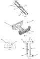
Fig. 1 schematically shows a "U" radiator provided with bypass; -
Fig. 2 shows the graph of the friction loss as a function of the flow rate of the cooling fluid both for the "U" radiator and for the "I" radiator. The point highlighted in the graph is the intervention point of the overpressure valve that levels the friction loss value of the "U" radiator; -
Fig. 3 shows a cross-sectional view of a tank included in a "U" radiator, with the baffle dividing the upper and lower volume put in evidence; -
Fig. 4 shows an overpressure valve coupled to the dividing baffle described above; -
Fig. 5 shows said dividing baffle; -
Fig. 6 shows a longitudinal section of the overpressure valve offigure 4 ; -
Fig. 7 schematically shows an "I" radiator provided with bypass; - With reference to
figures 1 and 2 , a preferred embodiment applied to a "U" radiator includes atank 2 with aninput opening 21 and an output opening 22 of acooling fluid 3 and a dividingbaffle 23 which divides the tank in two volumes Vsup and Vinf and atube bundle 1 whose function is to connect said volumes with each other, as to allow the cooling fluid to pass through the radiator first in a direction and then in the opposite. - Said dividing
baffle 23 is provided, in said preferred embodiment, with anoverpressure valve 24 whose function is to provide a bypass for the tube bundle, allowing the passage of a portion of the fluid directly from the input opening to the output opening. In this way, said portion of flow rate does not pass through the tube bundle and the pressure generated in the radiator levels itself (seeFig. 2 ). - Even if said portion of flow rate that is conveyed directly from the input to the output of the radiator is not cooled by the radiator, the engine will not have problems, because the flow rate that passes through the tube bundle is more than sufficient to reach the wanted overall lowering of the temperature of the cooling fluid.
- In figures from 3 to 6 it is shown the
overpressure valve 24 according to the invention. It includes (i) arounded head 242 whose lower part is connected, and is preferably coaxial, with (ii) asmall shaft 241; (iii) asupport 244 integral with thetank 2 and provided with ahole 245 which is compatible with the section of saidsmall shaft 241; (iv) acounter spring 243 whose function is to maintain therounded head 242 in contact with the edges of ahole 231 made in the radiator and in particular in the dividingbaffle 23. - Said counter spring is adjusted as to allow the lowering of the
rounded head 242 when a predetermined pressure level in the upper volume Vsup of thetank 2 is reached, and to allow the passage of a certain quantity of cooling fluid through thehole 231 and also through thesupport 244 provided with appropriate openings for the passage of the fluid. - In particular, said
hole 245 made in thesupport 244 constitutes a real baffle leaning out toward therounded head 242 as to obtain a twofold function: - keep the
small shaft 241 in axis; - determine the maximun limit of opening of the
overpressure valve 24, that is the maximum lowering of therounded head 242. - With reference to
figure 7 , another preferred embodiment of cooling radiator with overpressure bypass is applied to an "I" radiator. In this case, the radiator comprises a tank 2' in which said input opening 21 is made, a tank 4' in which said output opening 22 is made, and saidtube bundle 1 whose function is to interconnect said tanks, as to make the cooling fluid pass through the radiator from a tank to the other. An advantage is that said bypass means comprise not only the saidoverpressure valve 24, but also anauxiliary pipe 25 that has the same function of thebaffle 23 illustrated in the "U" radiator, that is whose function is to convey a portion of the flow rate of the cooling fluid from the input opening 21 to the output opening 22, when said valve comes into operation. In this case, saidhole 231 is bored at the boundary between saidtank 2 and saidauxiliary pipe 25. - The particular embodiments described here do not limit the scope of this invention which covers all the alternative embodiments defined by the claims.
Claims (9)
- Cooling radiator comprising: a tube bundle (1), an input opening (21) and an output opening (22) of a cooling fluid (3), and bypass means (24) whose function is to directly convey a portion of the flow rate of the cooling fluid from said input opening to said output opening, limiting the flow rate of cooling fluid in the tube bundle and the pressure developed in it, when this pressure exceeds a predetermined value; said bypass means are obtained by means of an overpressure valve (24) characterized in that the valve (24) comprises (i) a rounded head (242) connected in a coaxial way with (ii) a small shaft (241); (iii) a support (244) integral with the radiator and provided with a hole (245) in which said small shaft (241) is inserted; (iv) a counter spring (243) keeping the rounded head (242) in contact with the edges of a hole (231) bored in the radiator;
a certain quantity of cooling fluid passing through said hole (231) and
said support (244) is positioned so as said quantity of cooling fluid passes also through the support (244) provided with appropriate openings for the passage of the fluid. - Radiator according to claim 1, of the "I" type comprising also a first tank (2') in which said input opening (21) is made, a second tank (4') in which said output opening (22) is made, and said tube bundle (1) whose function is to interconnect said first and second tanks, as to make the cooling fluid pass through the radiator from a tank to the other, being said first and second tank placed one opposite the other.
- Radiator according to claim 1, of the "U" type comprising also a third tank (2) divided in two volumes by a baffle (23), and a tube bundle (1) whose function is to interconnect said volumes with each other, as to make the cooling fluid pass through the radiator first in one direction and then in the opposite direction, being a first of said two volumes connected to said input opening (21) and a second of said two volumes connected to said output opening (22).
- Radiator according to claim 3, provided also with a fourth tank (4) placed opposite to said third tank (2), said fourth tank having the function to take in an extremity of the incoming and outgoing tube bundle (1) of the cooling fluid, in order to interconnect said two volumes.
- Radiator according to claims 3, in which said hole (231) in contact with said rounded head (242) of said overpressure valve (24), is bored in said dividing baffle (23).
- Radiator according to any of the claims 1-5, in which said bypass means comprise also an auxiliary pipe (25) through which the exceeding cooling fluid flows, being conveyed by means of said overpressure valve (24).
- Radiator according to claim 6, in which said hole (231), in contact with said rounded head (242) of said overpressure valve (24), is bored at the boundary between the tank (2), provided with the input opening and said auxiliary pipe (25).
- Endothermic engine provided with liquid cooling characterized by the fact that it comprises a radiator according to any of the claims 1-7.
- Vehicle provided with endothermic engine according to claim 8.
Priority Applications (2)
| Application Number | Priority Date | Filing Date | Title |
|---|---|---|---|
| EP07119716.4A EP2056042B1 (en) | 2007-10-31 | 2007-10-31 | Cooling radiator with overpressure bypass and endothermic engine comprising said radiator |
| ES07119716.4T ES2553959T3 (en) | 2007-10-31 | 2007-10-31 | Cooling radiator with overpressure bypass and endothermic motor comprising said radiator |
Applications Claiming Priority (1)
| Application Number | Priority Date | Filing Date | Title |
|---|---|---|---|
| EP07119716.4A EP2056042B1 (en) | 2007-10-31 | 2007-10-31 | Cooling radiator with overpressure bypass and endothermic engine comprising said radiator |
Publications (2)
| Publication Number | Publication Date |
|---|---|
| EP2056042A1 EP2056042A1 (en) | 2009-05-06 |
| EP2056042B1 true EP2056042B1 (en) | 2015-09-16 |
Family
ID=39111828
Family Applications (1)
| Application Number | Title | Priority Date | Filing Date |
|---|---|---|---|
| EP07119716.4A Active EP2056042B1 (en) | 2007-10-31 | 2007-10-31 | Cooling radiator with overpressure bypass and endothermic engine comprising said radiator |
Country Status (2)
| Country | Link |
|---|---|
| EP (1) | EP2056042B1 (en) |
| ES (1) | ES2553959T3 (en) |
Families Citing this family (1)
| Publication number | Priority date | Publication date | Assignee | Title |
|---|---|---|---|---|
| US9810486B2 (en) | 2013-12-20 | 2017-11-07 | Denso International America, Inc. | Heat exchanger pressure adjustable baffle |
Family Cites Families (6)
| Publication number | Priority date | Publication date | Assignee | Title |
|---|---|---|---|---|
| US3920067A (en) * | 1973-04-11 | 1975-11-18 | Mms Ltd | Heat exchanger for continuous flow fluid heater |
| GB2272506B (en) * | 1992-11-02 | 1996-07-24 | Nippon Denso Co | Refrigerant condenser |
| US6253837B1 (en) * | 1998-03-23 | 2001-07-03 | Long Manufacturing Ltd. | By-pass values for heat exchanger |
| US6161614A (en) * | 1998-03-27 | 2000-12-19 | Karmazin Products Corporation | Aluminum header construction |
| JP2001174190A (en) * | 1999-12-17 | 2001-06-29 | Denso Corp | Double heat exchanger |
| US20030019620A1 (en) * | 2001-07-30 | 2003-01-30 | Pineo Gregory Merle | Plug bypass valves and heat exchangers |
-
2007
- 2007-10-31 ES ES07119716.4T patent/ES2553959T3/en active Active
- 2007-10-31 EP EP07119716.4A patent/EP2056042B1/en active Active
Also Published As
| Publication number | Publication date |
|---|---|
| ES2553959T3 (en) | 2015-12-15 |
| EP2056042A1 (en) | 2009-05-06 |
Similar Documents
| Publication | Publication Date | Title |
|---|---|---|
| KR101339250B1 (en) | Heat exchanger for vehicle | |
| EP2012017A3 (en) | Capacity modulated compressor | |
| US20160215664A1 (en) | Thermal Management Unit for Vehicle Powertrain | |
| CN101849157A (en) | Heat exchangers, especially oil coolers | |
| EP1942305A3 (en) | Internal heat exchanger integrated with gas cooler | |
| CN103161559A (en) | Thermostat housing which provides optimized coolant flow | |
| EA020099B1 (en) | Cooling water circuit for stationary engine | |
| US7832467B2 (en) | Oil cooler | |
| US20110067853A1 (en) | Fluid cooling device for a motor vehicle | |
| EP1628100A2 (en) | Cogeneration system and exhaust gas heat exchanger assembly thereof | |
| US10126068B2 (en) | Fluid flow heat transfer box for multiple fluids with fluid flow control device | |
| US20150107807A1 (en) | Heat exchanger | |
| EP2056042A1 (en) | Cooling radiator with overpressure bypass ans endothermic engine comprising said radiator | |
| JP4711790B2 (en) | Air conditioner | |
| AU2006274484B2 (en) | Thermo-siphon restrictor valve | |
| JP4375045B2 (en) | Heat exchanger | |
| US12366414B2 (en) | Heat exchanger | |
| EP0053003A1 (en) | Heat exchanger | |
| GB2090957A (en) | Heat exchanger | |
| CN115103953A (en) | Temperature control system, vehicle provided with the temperature control system, and method for controlling operation of the temperature control system | |
| JP2007016651A (en) | Oil temperature control device | |
| CN108627036B (en) | Plate heat exchanger with constant temperature function | |
| JP2001227624A (en) | Oil cooler for automobile | |
| KR102730529B1 (en) | Exhaust heat recovery system | |
| KR20100067153A (en) | Radiator tank and oil cooler assembly |
Legal Events
| Date | Code | Title | Description |
|---|---|---|---|
| PUAI | Public reference made under article 153(3) epc to a published international application that has entered the european phase |
Free format text: ORIGINAL CODE: 0009012 |
|
| AK | Designated contracting states |
Kind code of ref document: A1 Designated state(s): AT BE BG CH CY CZ DE DK EE ES FI FR GB GR HU IE IS IT LI LT LU LV MC MT NL PL PT RO SE SI SK TR |
|
| AX | Request for extension of the european patent |
Extension state: AL BA HR MK RS |
|
| 17P | Request for examination filed |
Effective date: 20091104 |
|
| 17Q | First examination report despatched |
Effective date: 20091201 |
|
| AKX | Designation fees paid |
Designated state(s): AT BE BG CH CY CZ DE DK EE ES FI FR GB GR HU IE IS IT LI LT LU LV MC MT NL PL PT RO SE SI SK TR |
|
| REG | Reference to a national code |
Ref country code: DE Ref legal event code: R079 Ref document number: 602007043121 Country of ref document: DE Free format text: PREVIOUS MAIN CLASS: F25B0039020000 Ipc: F25B0041040000 |
|
| GRAP | Despatch of communication of intention to grant a patent |
Free format text: ORIGINAL CODE: EPIDOSNIGR1 |
|
| RIC1 | Information provided on ipc code assigned before grant |
Ipc: F25B 39/02 20060101ALI20150206BHEP Ipc: F25B 41/04 20060101AFI20150206BHEP |
|
| INTG | Intention to grant announced |
Effective date: 20150306 |
|
| GRAS | Grant fee paid |
Free format text: ORIGINAL CODE: EPIDOSNIGR3 |
|
| GRAA | (expected) grant |
Free format text: ORIGINAL CODE: 0009210 |
|
| AK | Designated contracting states |
Kind code of ref document: B1 Designated state(s): AT BE BG CH CY CZ DE DK EE ES FI FR GB GR HU IE IS IT LI LT LU LV MC MT NL PL PT RO SE SI SK TR |
|
| REG | Reference to a national code |
Ref country code: GB Ref legal event code: FG4D |
|
| REG | Reference to a national code |
Ref country code: CH Ref legal event code: EP |
|
| REG | Reference to a national code |
Ref country code: IE Ref legal event code: FG4D |
|
| REG | Reference to a national code |
Ref country code: AT Ref legal event code: REF Ref document number: 750123 Country of ref document: AT Kind code of ref document: T Effective date: 20151015 |
|
| REG | Reference to a national code |
Ref country code: DE Ref legal event code: R096 Ref document number: 602007043121 Country of ref document: DE |
|
| REG | Reference to a national code |
Ref country code: FR Ref legal event code: PLFP Year of fee payment: 9 |
|
| REG | Reference to a national code |
Ref country code: CH Ref legal event code: NV Representative=s name: ISLER AND PEDRAZZINI AG, CH |
|
| REG | Reference to a national code |
Ref country code: SE Ref legal event code: TRGR Ref country code: ES Ref legal event code: FG2A Ref document number: 2553959 Country of ref document: ES Kind code of ref document: T3 Effective date: 20151215 |
|
| REG | Reference to a national code |
Ref country code: NL Ref legal event code: FP |
|
| PG25 | Lapsed in a contracting state [announced via postgrant information from national office to epo] |
Ref country code: GR Free format text: LAPSE BECAUSE OF FAILURE TO SUBMIT A TRANSLATION OF THE DESCRIPTION OR TO PAY THE FEE WITHIN THE PRESCRIBED TIME-LIMIT Effective date: 20151217 Ref country code: LV Free format text: LAPSE BECAUSE OF FAILURE TO SUBMIT A TRANSLATION OF THE DESCRIPTION OR TO PAY THE FEE WITHIN THE PRESCRIBED TIME-LIMIT Effective date: 20150916 Ref country code: LT Free format text: LAPSE BECAUSE OF FAILURE TO SUBMIT A TRANSLATION OF THE DESCRIPTION OR TO PAY THE FEE WITHIN THE PRESCRIBED TIME-LIMIT Effective date: 20150916 Ref country code: FI Free format text: LAPSE BECAUSE OF FAILURE TO SUBMIT A TRANSLATION OF THE DESCRIPTION OR TO PAY THE FEE WITHIN THE PRESCRIBED TIME-LIMIT Effective date: 20150916 |
|
| REG | Reference to a national code |
Ref country code: LT Ref legal event code: MG4D |
|
| REG | Reference to a national code |
Ref country code: AT Ref legal event code: MK05 Ref document number: 750123 Country of ref document: AT Kind code of ref document: T Effective date: 20150916 |
|
| PG25 | Lapsed in a contracting state [announced via postgrant information from national office to epo] |
Ref country code: IS Free format text: LAPSE BECAUSE OF FAILURE TO SUBMIT A TRANSLATION OF THE DESCRIPTION OR TO PAY THE FEE WITHIN THE PRESCRIBED TIME-LIMIT Effective date: 20160116 Ref country code: EE Free format text: LAPSE BECAUSE OF FAILURE TO SUBMIT A TRANSLATION OF THE DESCRIPTION OR TO PAY THE FEE WITHIN THE PRESCRIBED TIME-LIMIT Effective date: 20150916 Ref country code: CZ Free format text: LAPSE BECAUSE OF FAILURE TO SUBMIT A TRANSLATION OF THE DESCRIPTION OR TO PAY THE FEE WITHIN THE PRESCRIBED TIME-LIMIT Effective date: 20150916 Ref country code: SK Free format text: LAPSE BECAUSE OF FAILURE TO SUBMIT A TRANSLATION OF THE DESCRIPTION OR TO PAY THE FEE WITHIN THE PRESCRIBED TIME-LIMIT Effective date: 20150916 |
|
| PG25 | Lapsed in a contracting state [announced via postgrant information from national office to epo] |
Ref country code: RO Free format text: LAPSE BECAUSE OF FAILURE TO SUBMIT A TRANSLATION OF THE DESCRIPTION OR TO PAY THE FEE WITHIN THE PRESCRIBED TIME-LIMIT Effective date: 20150916 Ref country code: AT Free format text: LAPSE BECAUSE OF FAILURE TO SUBMIT A TRANSLATION OF THE DESCRIPTION OR TO PAY THE FEE WITHIN THE PRESCRIBED TIME-LIMIT Effective date: 20150916 Ref country code: PL Free format text: LAPSE BECAUSE OF FAILURE TO SUBMIT A TRANSLATION OF THE DESCRIPTION OR TO PAY THE FEE WITHIN THE PRESCRIBED TIME-LIMIT Effective date: 20150916 Ref country code: PT Free format text: LAPSE BECAUSE OF FAILURE TO SUBMIT A TRANSLATION OF THE DESCRIPTION OR TO PAY THE FEE WITHIN THE PRESCRIBED TIME-LIMIT Effective date: 20160118 |
|
| REG | Reference to a national code |
Ref country code: DE Ref legal event code: R097 Ref document number: 602007043121 Country of ref document: DE |
|
| PG25 | Lapsed in a contracting state [announced via postgrant information from national office to epo] |
Ref country code: MC Free format text: LAPSE BECAUSE OF FAILURE TO SUBMIT A TRANSLATION OF THE DESCRIPTION OR TO PAY THE FEE WITHIN THE PRESCRIBED TIME-LIMIT Effective date: 20150916 |
|
| PLBE | No opposition filed within time limit |
Free format text: ORIGINAL CODE: 0009261 |
|
| STAA | Information on the status of an ep patent application or granted ep patent |
Free format text: STATUS: NO OPPOSITION FILED WITHIN TIME LIMIT |
|
| REG | Reference to a national code |
Ref country code: IE Ref legal event code: MM4A |
|
| 26N | No opposition filed |
Effective date: 20160617 |
|
| PG25 | Lapsed in a contracting state [announced via postgrant information from national office to epo] |
Ref country code: DK Free format text: LAPSE BECAUSE OF FAILURE TO SUBMIT A TRANSLATION OF THE DESCRIPTION OR TO PAY THE FEE WITHIN THE PRESCRIBED TIME-LIMIT Effective date: 20150916 |
|
| REG | Reference to a national code |
Ref country code: FR Ref legal event code: PLFP Year of fee payment: 10 |
|
| PG25 | Lapsed in a contracting state [announced via postgrant information from national office to epo] |
Ref country code: IE Free format text: LAPSE BECAUSE OF NON-PAYMENT OF DUE FEES Effective date: 20151031 |
|
| PG25 | Lapsed in a contracting state [announced via postgrant information from national office to epo] |
Ref country code: SI Free format text: LAPSE BECAUSE OF FAILURE TO SUBMIT A TRANSLATION OF THE DESCRIPTION OR TO PAY THE FEE WITHIN THE PRESCRIBED TIME-LIMIT Effective date: 20150916 |
|
| PG25 | Lapsed in a contracting state [announced via postgrant information from national office to epo] |
Ref country code: BE Free format text: LAPSE BECAUSE OF FAILURE TO SUBMIT A TRANSLATION OF THE DESCRIPTION OR TO PAY THE FEE WITHIN THE PRESCRIBED TIME-LIMIT Effective date: 20150916 |
|
| PG25 | Lapsed in a contracting state [announced via postgrant information from national office to epo] |
Ref country code: BG Free format text: LAPSE BECAUSE OF FAILURE TO SUBMIT A TRANSLATION OF THE DESCRIPTION OR TO PAY THE FEE WITHIN THE PRESCRIBED TIME-LIMIT Effective date: 20150916 Ref country code: HU Free format text: LAPSE BECAUSE OF FAILURE TO SUBMIT A TRANSLATION OF THE DESCRIPTION OR TO PAY THE FEE WITHIN THE PRESCRIBED TIME-LIMIT; INVALID AB INITIO Effective date: 20071031 |
|
| PG25 | Lapsed in a contracting state [announced via postgrant information from national office to epo] |
Ref country code: CY Free format text: LAPSE BECAUSE OF FAILURE TO SUBMIT A TRANSLATION OF THE DESCRIPTION OR TO PAY THE FEE WITHIN THE PRESCRIBED TIME-LIMIT Effective date: 20150916 |
|
| PG25 | Lapsed in a contracting state [announced via postgrant information from national office to epo] |
Ref country code: TR Free format text: LAPSE BECAUSE OF FAILURE TO SUBMIT A TRANSLATION OF THE DESCRIPTION OR TO PAY THE FEE WITHIN THE PRESCRIBED TIME-LIMIT Effective date: 20150916 Ref country code: MT Free format text: LAPSE BECAUSE OF FAILURE TO SUBMIT A TRANSLATION OF THE DESCRIPTION OR TO PAY THE FEE WITHIN THE PRESCRIBED TIME-LIMIT Effective date: 20150916 |
|
| REG | Reference to a national code |
Ref country code: FR Ref legal event code: PLFP Year of fee payment: 11 |
|
| PG25 | Lapsed in a contracting state [announced via postgrant information from national office to epo] |
Ref country code: LU Free format text: LAPSE BECAUSE OF NON-PAYMENT OF DUE FEES Effective date: 20151031 |
|
| PGFP | Annual fee paid to national office [announced via postgrant information from national office to epo] |
Ref country code: CH Payment date: 20171013 Year of fee payment: 11 Ref country code: SE Payment date: 20171011 Year of fee payment: 11 Ref country code: NL Payment date: 20171016 Year of fee payment: 11 |
|
| REG | Reference to a national code |
Ref country code: FR Ref legal event code: PLFP Year of fee payment: 12 |
|
| REG | Reference to a national code |
Ref country code: CH Ref legal event code: PL |
|
| REG | Reference to a national code |
Ref country code: NL Ref legal event code: MM Effective date: 20181101 |
|
| REG | Reference to a national code |
Ref country code: SE Ref legal event code: EUG |
|
| PG25 | Lapsed in a contracting state [announced via postgrant information from national office to epo] |
Ref country code: NL Free format text: LAPSE BECAUSE OF NON-PAYMENT OF DUE FEES Effective date: 20181101 Ref country code: SE Free format text: LAPSE BECAUSE OF NON-PAYMENT OF DUE FEES Effective date: 20181101 |
|
| PG25 | Lapsed in a contracting state [announced via postgrant information from national office to epo] |
Ref country code: LI Free format text: LAPSE BECAUSE OF NON-PAYMENT OF DUE FEES Effective date: 20181031 Ref country code: CH Free format text: LAPSE BECAUSE OF NON-PAYMENT OF DUE FEES Effective date: 20181031 |
|
| REG | Reference to a national code |
Ref country code: DE Ref legal event code: R079 Ref document number: 602007043121 Country of ref document: DE Free format text: PREVIOUS MAIN CLASS: F25B0041040000 Ipc: F25B0041200000 |
|
| P01 | Opt-out of the competence of the unified patent court (upc) registered |
Effective date: 20230523 |
|
| PGFP | Annual fee paid to national office [announced via postgrant information from national office to epo] |
Ref country code: DE Payment date: 20251028 Year of fee payment: 19 |
|
| PGFP | Annual fee paid to national office [announced via postgrant information from national office to epo] |
Ref country code: GB Payment date: 20251023 Year of fee payment: 19 |
|
| PGFP | Annual fee paid to national office [announced via postgrant information from national office to epo] |
Ref country code: IT Payment date: 20251009 Year of fee payment: 19 |
|
| PGFP | Annual fee paid to national office [announced via postgrant information from national office to epo] |
Ref country code: FR Payment date: 20251027 Year of fee payment: 19 |
|
| PGFP | Annual fee paid to national office [announced via postgrant information from national office to epo] |
Ref country code: ES Payment date: 20251118 Year of fee payment: 19 |