EP2055917A1 - Fuel injection quantity control system for general-purpose engine - Google Patents
Fuel injection quantity control system for general-purpose engine Download PDFInfo
- Publication number
- EP2055917A1 EP2055917A1 EP08017833A EP08017833A EP2055917A1 EP 2055917 A1 EP2055917 A1 EP 2055917A1 EP 08017833 A EP08017833 A EP 08017833A EP 08017833 A EP08017833 A EP 08017833A EP 2055917 A1 EP2055917 A1 EP 2055917A1
- Authority
- EP
- European Patent Office
- Prior art keywords
- acceleration state
- time period
- acceleration
- predetermined time
- fuel injection
- Prior art date
- Legal status (The legal status is an assumption and is not a legal conclusion. Google has not performed a legal analysis and makes no representation as to the accuracy of the status listed.)
- Granted
Links
- 239000000446 fuel Substances 0.000 title claims abstract description 68
- 238000002347 injection Methods 0.000 title claims abstract description 47
- 239000007924 injection Substances 0.000 title claims abstract description 47
- 230000001133 acceleration Effects 0.000 claims abstract description 107
- 230000001965 increasing effect Effects 0.000 claims abstract description 27
- 230000008859 change Effects 0.000 claims abstract description 19
- 230000001939 inductive effect Effects 0.000 claims abstract description 6
- 238000001514 detection method Methods 0.000 claims description 14
- 230000003247 decreasing effect Effects 0.000 claims description 11
- 230000007423 decrease Effects 0.000 description 24
- 238000000034 method Methods 0.000 description 22
- 230000008569 process Effects 0.000 description 17
- 238000001816 cooling Methods 0.000 description 3
- 238000010586 diagram Methods 0.000 description 2
- 238000011144 upstream manufacturing Methods 0.000 description 2
- 230000007246 mechanism Effects 0.000 description 1
- 238000012986 modification Methods 0.000 description 1
- 230000004048 modification Effects 0.000 description 1
- 230000009467 reduction Effects 0.000 description 1
Images





Classifications
-
- F—MECHANICAL ENGINEERING; LIGHTING; HEATING; WEAPONS; BLASTING
- F02—COMBUSTION ENGINES; HOT-GAS OR COMBUSTION-PRODUCT ENGINE PLANTS
- F02D—CONTROLLING COMBUSTION ENGINES
- F02D41/00—Electrical control of supply of combustible mixture or its constituents
- F02D41/02—Circuit arrangements for generating control signals
- F02D41/04—Introducing corrections for particular operating conditions
- F02D41/10—Introducing corrections for particular operating conditions for acceleration
-
- F—MECHANICAL ENGINEERING; LIGHTING; HEATING; WEAPONS; BLASTING
- F02—COMBUSTION ENGINES; HOT-GAS OR COMBUSTION-PRODUCT ENGINE PLANTS
- F02D—CONTROLLING COMBUSTION ENGINES
- F02D41/00—Electrical control of supply of combustible mixture or its constituents
- F02D41/02—Circuit arrangements for generating control signals
- F02D41/04—Introducing corrections for particular operating conditions
- F02D41/045—Detection of accelerating or decelerating state
-
- F—MECHANICAL ENGINEERING; LIGHTING; HEATING; WEAPONS; BLASTING
- F02—COMBUSTION ENGINES; HOT-GAS OR COMBUSTION-PRODUCT ENGINE PLANTS
- F02B—INTERNAL-COMBUSTION PISTON ENGINES; COMBUSTION ENGINES IN GENERAL
- F02B63/00—Adaptations of engines for driving pumps, hand-held tools or electric generators; Portable combinations of engines with engine-driven devices
-
- F—MECHANICAL ENGINEERING; LIGHTING; HEATING; WEAPONS; BLASTING
- F02—COMBUSTION ENGINES; HOT-GAS OR COMBUSTION-PRODUCT ENGINE PLANTS
- F02D—CONTROLLING COMBUSTION ENGINES
- F02D11/00—Arrangements for, or adaptations to, non-automatic engine control initiation means, e.g. operator initiated
- F02D11/06—Arrangements for, or adaptations to, non-automatic engine control initiation means, e.g. operator initiated characterised by non-mechanical control linkages, e.g. fluid control linkages or by control linkages with power drive or assistance
- F02D11/10—Arrangements for, or adaptations to, non-automatic engine control initiation means, e.g. operator initiated characterised by non-mechanical control linkages, e.g. fluid control linkages or by control linkages with power drive or assistance of the electric type
- F02D2011/101—Arrangements for, or adaptations to, non-automatic engine control initiation means, e.g. operator initiated characterised by non-mechanical control linkages, e.g. fluid control linkages or by control linkages with power drive or assistance of the electric type characterised by the means for actuating the throttles
- F02D2011/102—Arrangements for, or adaptations to, non-automatic engine control initiation means, e.g. operator initiated characterised by non-mechanical control linkages, e.g. fluid control linkages or by control linkages with power drive or assistance of the electric type characterised by the means for actuating the throttles at least one throttle being moved only by an electric actuator
-
- F—MECHANICAL ENGINEERING; LIGHTING; HEATING; WEAPONS; BLASTING
- F02—COMBUSTION ENGINES; HOT-GAS OR COMBUSTION-PRODUCT ENGINE PLANTS
- F02D—CONTROLLING COMBUSTION ENGINES
- F02D2200/00—Input parameters for engine control
- F02D2200/02—Input parameters for engine control the parameters being related to the engine
- F02D2200/04—Engine intake system parameters
- F02D2200/0404—Throttle position
-
- F—MECHANICAL ENGINEERING; LIGHTING; HEATING; WEAPONS; BLASTING
- F02—COMBUSTION ENGINES; HOT-GAS OR COMBUSTION-PRODUCT ENGINE PLANTS
- F02D—CONTROLLING COMBUSTION ENGINES
- F02D2200/00—Input parameters for engine control
- F02D2200/60—Input parameters for engine control said parameters being related to the driver demands or status
- F02D2200/602—Pedal position
-
- F—MECHANICAL ENGINEERING; LIGHTING; HEATING; WEAPONS; BLASTING
- F02—COMBUSTION ENGINES; HOT-GAS OR COMBUSTION-PRODUCT ENGINE PLANTS
- F02D—CONTROLLING COMBUSTION ENGINES
- F02D41/00—Electrical control of supply of combustible mixture or its constituents
- F02D41/30—Controlling fuel injection
- F02D41/32—Controlling fuel injection of the low pressure type
- F02D41/34—Controlling fuel injection of the low pressure type with means for controlling injection timing or duration
-
- F—MECHANICAL ENGINEERING; LIGHTING; HEATING; WEAPONS; BLASTING
- F02—COMBUSTION ENGINES; HOT-GAS OR COMBUSTION-PRODUCT ENGINE PLANTS
- F02D—CONTROLLING COMBUSTION ENGINES
- F02D9/00—Controlling engines by throttling air or fuel-and-air induction conduits or exhaust conduits
- F02D9/08—Throttle valves specially adapted therefor; Arrangements of such valves in conduits
- F02D9/10—Throttle valves specially adapted therefor; Arrangements of such valves in conduits having pivotally-mounted flaps
- F02D9/1035—Details of the valve housing
- F02D9/105—Details of the valve housing having a throttle position sensor
Definitions
- the determination of the acceleration state is stopped until a fifth predetermined time period passes. Accordingly, it is possible to prevent the unnecessary correction of the amount of fuel injected by the fuel injection valves toward an increased side when the throttle valves successively open and close in accordance with successive opening/closing operations of the throttle operator, thereby preventing any after-burn from occurring.
- Fig. 1 is a partial cross-sectional front view of a general-purpose engine having a fuel injection control system according to the present invention
- Fig. 2 is a plan view seen in the direction of arrow 2 in Fig. 1 ;
- Fig. 3 is a view showing a throttle body seen in the direction of arrows 3-3 in Fig. 1 ;
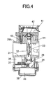
- Fig. 4 is a cross-sectional view taken along line 4-4 in Fig. 3 ;
- Fig. 5 is a cross-sectional view taken along line 5-5 in Fig. 3 ;
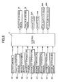
- Fig. 7 is a block diagram showing a configuration of a fuel injection quantity control section of the control system's control unit
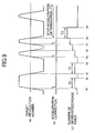
- Fig. 9 is a timing chart showing an example of a determination made by the acceleration state determinor.
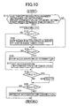
- Fig. 10 is a flowchart showing a procedure through which the acceleration state determinor determines whether an acceleration determination should be performed according to a second embodiment of the present invention.
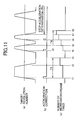
- Fig. 11 is a timing chart showing an example of the acceleration determination performed in Fig. 10 .
- the second bank BB includes a second cylinder block 17B joined to an upper part of the crankcase 16 to form a V-shape with the first cylinder block 17A, a second cylinder head 18B joined to the second cylinder block 17B, and a second head cover 19B joined to the second cylinder head 18B.
- a crankshaft 20 is rotatably supported by the crankcase 16, and one end of the crankshaft 20 protrudes from one side surface of the crankcase 16 toward outside.
- the other side of the engine body 15 is covered with a cover 21 attached to the crankcase 16.
- the cover 21 is provided with an air suction port 23 taking in air from the outside by using a cooling fan 22 fixed to the crankshaft 20 inside the cover 21.
- the first and second cylinder heads 18A and 18B are provided with spark plugs 24A and 24B, respectively.
- Intake ports are provided, respectively, in side surfaces of the first and second cylinder heads 18A and 18B on the side covered with the cover 21.
- the downstream ends of first and second intake pipes 28A and 28B extending to the intake ports of the cylinder heads 18A and 18b are connected to the first and second cylinder heads 18A and 18B, respectively, while the upstream ends of the first and second intake pipes 28A and 28B are connected to the downstream ends of first and second throttle bodies 29A and 29B, respectively.
- the upstream ends of the first and second throttle bodies 29A and 29B are both connected to an air cleaner 30 disposed above a part of the engine body 15, located between the first and second banks BA and BB.
- an intake passage 31 leading to the corresponding intake port is formed in the first throttle body 29A.
- a butterfly throttle valve 32 controlling the opening degree of the intake passage 31 is fixed to a valve stem 33 provided across the intake passage 31 and rotatably supported by the first throttle body 29A.
- a throttle driving means 34 is connected to one end of the valve stem 33.
- the throttle driving means 34 includes an electric motor 35, and a reduction gear mechanism 36 reducing the rotation power of the electric motor 35 and then transmitting the resultant rotation power to the valve stem 33.
- a working chamber 39 is formed by a cylindrical case 37 integrally provided on the first throttle body 29A, and a closure member 38 is fastened to the case 37 to close the opening end of the case 37.
- the throttle driving means 34 is housed in the functioning chamber 39.
- a sensor unit 41 is attached to the first throttle body 29A and faces the other end of the valve stem 33.
- the sensor unit 41 includes a throttle position sensor 42 connected to the other end of the valve stem 33, which detects the opening degree of the throttle valve 32, an intake-air temperature sensor 43 detecting the temperature of intake air flowing through the intake passage 31, and an intake-air pressure sensor 44 detecting the intake-air pressure.
- a fuel injection valve 45A injecting fuel into the intake passage 31 is attached to a part of the first throttle body 29A located on the downstream side relative to the throttle valve 32.
- the fuel injection valve 45A is disposed between the first throttle body 29A and a cap 46 fitted to a rear portion of the fuel injection valve 45A, the valve 45A being fastened to the first throttle body 29A.
- the second throttle body 29B has basically the same configuration as that of the first throttle body 29A.
- the second throttle body 29B as the first throttle body 29A, includes a throttle driving means 34, a throttle position sensor 42, an intake-air temperature sensor 43, and an intake-air pressure sensor 44, wherein a fuel injection valve 45B is attached to the second throttle body 29B.
- a knob 47 which serves as a throttle operating means for setting the opening degrees of the throttle valves 32 of the first and second banks BA and BB by manual operation, is disposed.
- the opening degree of both throttle valves 32 is set in accordance with a value detected by a potentiometer 48 (see Fig. 6 ), which detects the rotation position of the knob 47.
- a support plate 49 supporting a control unit C for controlling the engine operation is attached to the second cylinder head 18B of the second bank BB out of the first and second banks BA and BB.
- values detected by the potentiometer 48, the revolution number sensor 26, the engine temperature sensors 27, the throttle position sensors 42, the intake-air temperature sensors 43, and the intake-air pressure sensors 44 are each inputted to the control unit C.
- the control unit C controls operation of the electric motor 35 in the throttle driving means 34, ignition timing of the spark plugs 24A and 24B in the banks BA and BB, and fuel injection of the fuel injection valves 45A and 45B provided, respectively, in the first and second throttle bodies 29A and 29B.
- step S1 When the acceleration state determining means 52 determines that the increase or the decrease in target revolution number was not a predetermined value, for example, 150 rpm, or more within the first predetermined time period T1, for example, 100 msec, in step S1, the process skips steps S2 and S3, and proceeds to step S4.
- the acceleration state determining means 52 determines whether the number of times N(n) is a predetermined number, for example, 4, or more. When it is determined that N(n) ⁇ 4, the process proceeds to step S5 to stop the acceleration determination. After an acceleration determination stop timer is set in step S6, the process proceeds to step S7.
- step S9 the acceleration state determining means 52 determines whether a measured time TEA measured by the acceleration determination stop timer has exceeded a third predetermined time period T3, for example, 6000 msec. When it is determined that the measured time TEA has exceeded the third predetermined time period T3, acceleration correction is approved in step S10.
- the acceleration state determining means 52 stops determination of the acceleration state until a third predetermined time period T3 passes.
- Figs. 10 and 11 show a second embodiment of the present invention.
- the acceleration state determining means 52 determines whether an acceleration determination should be performed, by following the procedure shown in Fig. 10 .
- the acceleration state determining means 52 determines whether an increase or a decrease in the target revolution number has reached a predetermined value, for example, 150 rpm, or more within the first predetermined time period T1, for example, 100 msec.
- a predetermined value for example, 150 rpm
- T1 for example, 100 msec.
- step S18 the acceleration state determining means 52 determines whether a measured time TCB measured by the timer for counting the number of successive times has exceeded a fourth predetermined time period T4, for example, 2500 msec.
- a measured time TCB measured by the timer for counting the number of successive times has exceeded a fourth predetermined time period T4, for example, 2500 msec.
- the process proceeds to step S19 to clear the number of times N(n), and then proceeds to step S20.
- the process skips step S19, and proceeds to step S20.
- step S20 the acceleration state determining means 52 determines whether a measured time TEB measured by the acceleration determination stop timer has exceeded a fifth predetermined time period T5, for example, 6000 msec. When it is determined that the measured time TEB has exceeded the fifth predetermined time period T5, acceleration correction is approved in step S21.
- the acceleration state determining means 52 stops determination of the acceleration state until a fifth predetermined time period T5, for example, 6000 msec, passes.
- the acceleration state determining means 52 determines that the engine is in an acceleration state. Upon such a decision, acceleration correction on the fuel injection quantity is performed, and the number of increase/decrease times is incremented to 1 at time point t1.
- a decrease in target revolution number is the predetermined value within the first predetermined time period T1 at time point t2 before the fourth predetermined time period T4 elapses since time point t1, the number of increase/decrease times is incremented to 2.
- the fourth predetermined time period T4 has elapsed time point t1, the number of increase/decrease times is cleared.
- an increase in the target revolution number is the predetermined value or more within the first predetermined time period T1.
- a decrease in the target revolution number is the predetermined value or more within the first predetermined time period T1.
- an increase in the target revolution number is the predetermined value or more within the first predetermined time period T1.
- a decrease in the target revolution number is the predetermined value or more within the first predetermined time period T1.
- acceleration correction of the fuel injection quantity is performed at each of times t4 and t6, after time point t7 when the number of increase/decrease times reached 4, acceleration determination is stopped until the fifth predetermined time period T5 elapses time point t7. Then, at time point t8 when the fourth predetermined time period T4 has elapsed time point t4, the number of increase/decrease times is cleared.
- a fuel injection control system corrects the amount of fuel injected by fuel injection valves toward an increased side when an acceleration state resulting from operation of a throttle occurs.
- a control unit includes a detector, an acceleration state determinor, and an acceleration corrector. When an increase in the detected value is a predetermined value or more within a first predetermined time period, the acceleration state determinor determines that a state is an acceleration state and inputs a signal inducing fuel-amount-increase correction to the acceleration corrector.
Landscapes
- Engineering & Computer Science (AREA)
- Chemical & Material Sciences (AREA)
- Combustion & Propulsion (AREA)
- Mechanical Engineering (AREA)
- General Engineering & Computer Science (AREA)
- Electrical Control Of Air Or Fuel Supplied To Internal-Combustion Engine (AREA)
Abstract
Description
- The present invention relates to a fuel injection quantity control system for a general-purpose engine having a control unit which corrects an amount of fuel injected by a fuel injection valve into an intake passage toward an increased side when an acceleration state results from operation of a throttle operator.
- A motorcycle engine in which a quantity of fuel injected at the time of vehicle acceleration is controlled by increase-quantity correction is disclosed by Japanese Patent Application Laid-open No.
8-135491 - Assume that the technique disclosed in Japanese Patent Application Laid-open No.
8-135491 - The present invention has been attained in view of the above-described drawback. An aspect of the present invention is to provide a fuel injection quantity control system for a general-purpose engine that is capable of avoiding after-burn from occurring by preventing unnecessary correction of the fuel injection amount toward an increased side when opening/closing operations are successively performed by the throttle operator.
- According to a first feature of the present invention, a fuel injection quantity control system is provided for a general-purpose engine, the control system including a control unit controlling an amount of fuel injected by a fuel injection valve into an intake passage, in accordance with an operation of a throttle operator which sets an opening degree of a throttle valve by manual operation. The control unit corrects or adjusts the amount of fuel injected by the fuel injection valve toward an increased side when an acceleration state resulting from operation of the throttle operator occurs. The control unit includes a detector which detects an index representing the opening degree of the throttle valve; an acceleration state determinor which determines the acceleration state based on a change in a value detected by the detector; and an acceleration corrector which corrects the amount of fuel injected by the fuel injection valve toward the increased side when the acceleration state determinor determines that the acceleration state is present. When an increase in value detected by the detector is a predetermined value or more within a first predetermined time period, the acceleration state determinor determines that the acceleration state is present, and then inputs a signal inducing a fuel-amount-increase correction to the acceleration corrector. When the state where an amount of change in the value detected by the detector continuously reaches a predetermined value or more in either of increasing or decreasing direction within a first predetermined time period a predetermined number of times or more before a second predetermined time period expires on each state, the determination of the acceleration state is stopped until a third predetermined time period passes.
- With the first feature, when the state where an amount of change in the value detected by the detector continuously reaches a predetermined value or more in either of increasing or decreasing direction within a first predetermined time period a predetermined number of times or more before a second predetermined time period expires on each state, the determination of the acceleration state is stopped until a third predetermined time period passes. Accordingly, it is possible to prevent the unnecessary correction of the amount of fuel injected by the fuel injection valves toward an increased side from being performed when the throttle valves successively open and close in accordance with successive opening/closing operations of the throttle operator, thereby preventing any after-burn from occurring.
- Further, according to a second feature of the present invention, when the state where an amount of change in the value detected by the detector reaches a predetermined value or more in either of increasing or decreasing direction within a first predetermined time period a predetermined number of times or more within a fourth predetermined time period, the determination of the acceleration state is stopped until a fifth predetermined time period passes.
- Moreover, with the second feature, when the state where an amount of change in the value detected by the detector for detecting an index representing the opening degrees of the throttle valves reaches a predetermined value or more in either of increasing or decreasing direction within a first predetermined time period a predetermined number of times or more within a fourth predetermined time period, the determination of the acceleration state is stopped until a fifth predetermined time period passes. Accordingly, it is possible to prevent the unnecessary correction of the amount of fuel injected by the fuel injection valves toward an increased side when the throttle valves successively open and close in accordance with successive opening/closing operations of the throttle operator, thereby preventing any after-burn from occurring.
- It should be noted that a knob in the embodiments described below corresponds to the throttle operating means of the present invention, and that target revolution number computing means corresponds to the detection means of the present invention.
- The present invention will be described below on the basis of embodiments illustrated in the accompanying drawings.
-
Fig. 1 is a partial cross-sectional front view of a general-purpose engine having a fuel injection control system according to the present invention; -
Fig. 2 is a plan view seen in the direction ofarrow 2 inFig. 1 ; -
Fig. 3 is a view showing a throttle body seen in the direction of arrows 3-3 inFig. 1 ; -
Fig. 4 is a cross-sectional view taken along line 4-4 inFig. 3 ; -
Fig. 5 is a cross-sectional view taken along line 5-5 inFig. 3 ; -
Fig. 6 is a block diagram showing a configuration of the control system according to a first embodiment of the present invention; -
Fig. 7 is a block diagram showing a configuration of a fuel injection quantity control section of the control system's control unit; -
Fig. 8 is a flowchart showing a process through which an acceleration state determinor determines whether acceleration determination should be performed; -
Fig. 9 is a timing chart showing an example of a determination made by the acceleration state determinor; -
Fig. 10 is a flowchart showing a procedure through which the acceleration state determinor determines whether an acceleration determination should be performed according to a second embodiment of the present invention; and -
Fig. 11 is a timing chart showing an example of the acceleration determination performed inFig. 10 . - Referring to
Figs. 1 and2 , the general-purpose engine is an air-cooling V-twin engine used in a working machine, for example. Anengine body 15 includes acrankcase 16 having first and second banks BA and BB, that together form a V-shape, disposed on thecrankcase 16. The first bank BA includes afirst cylinder block 17A joined to an upper part of thecrankcase 16, afirst cylinder head 18A joined to thefirst cylinder block 17A, and afirst head cover 19A joined to thefirst cylinder head 18A. The second bank BB includes asecond cylinder block 17B joined to an upper part of thecrankcase 16 to form a V-shape with thefirst cylinder block 17A, asecond cylinder head 18B joined to thesecond cylinder block 17B, and asecond head cover 19B joined to thesecond cylinder head 18B. - A
crankshaft 20 is rotatably supported by thecrankcase 16, and one end of thecrankshaft 20 protrudes from one side surface of thecrankcase 16 toward outside. The other side of theengine body 15 is covered with acover 21 attached to thecrankcase 16. Thecover 21 is provided with anair suction port 23 taking in air from the outside by using acooling fan 22 fixed to thecrankshaft 20 inside thecover 21. In addition, the first andsecond cylinder heads spark plugs - A
protrusion 25 is provided on the outer periphery of thecooling fan 22 in a protruding manner. Arevolution number sensor 26 for detecting a revolution number of thecrankshaft 20, i.e. the revolution number of the engine, by detecting theprotrusion 25 is attached to an inner surface of thecrankcase 16. Moreover,engine temperature sensors engine body 15 are attached to the first andsecond cylinder heads - Intake ports (not shown) are provided, respectively, in side surfaces of the first and
second cylinder heads cover 21. The downstream ends of first andsecond intake pipes cylinder heads 18A and 18b are connected to the first andsecond cylinder heads second intake pipes second throttle bodies second throttle bodies air cleaner 30 disposed above a part of theengine body 15, located between the first and second banks BA and BB. - Referring to
Figs. 3 and4 , anintake passage 31 leading to the corresponding intake port is formed in thefirst throttle body 29A. Abutterfly throttle valve 32 controlling the opening degree of theintake passage 31 is fixed to avalve stem 33 provided across theintake passage 31 and rotatably supported by thefirst throttle body 29A. - A throttle driving means 34 is connected to one end of the
valve stem 33. The throttle driving means 34 includes anelectric motor 35, and areduction gear mechanism 36 reducing the rotation power of theelectric motor 35 and then transmitting the resultant rotation power to thevalve stem 33. A workingchamber 39 is formed by acylindrical case 37 integrally provided on thefirst throttle body 29A, and aclosure member 38 is fastened to thecase 37 to close the opening end of thecase 37. The throttle driving means 34 is housed in thefunctioning chamber 39. - A
sensor unit 41 is attached to thefirst throttle body 29A and faces the other end of thevalve stem 33. Thesensor unit 41 includes athrottle position sensor 42 connected to the other end of thevalve stem 33, which detects the opening degree of thethrottle valve 32, an intake-air temperature sensor 43 detecting the temperature of intake air flowing through theintake passage 31, and an intake-air pressure sensor 44 detecting the intake-air pressure. - Referring to
Fig. 5 together, afuel injection valve 45A injecting fuel into theintake passage 31 is attached to a part of thefirst throttle body 29A located on the downstream side relative to thethrottle valve 32. Thefuel injection valve 45A is disposed between thefirst throttle body 29A and acap 46 fitted to a rear portion of thefuel injection valve 45A, thevalve 45A being fastened to thefirst throttle body 29A. - The
second throttle body 29B has basically the same configuration as that of thefirst throttle body 29A. Thus, thesecond throttle body 29B, as thefirst throttle body 29A, includes a throttle driving means 34, athrottle position sensor 42, an intake-air temperature sensor 43, and an intake-air pressure sensor 44, wherein afuel injection valve 45B is attached to thesecond throttle body 29B. - On a part of the
cover 21 located between the first and second banks BA and BB, aknob 47, which serves as a throttle operating means for setting the opening degrees of thethrottle valves 32 of the first and second banks BA and BB by manual operation, is disposed. The opening degree of boththrottle valves 32 is set in accordance with a value detected by a potentiometer 48 (seeFig. 6 ), which detects the rotation position of theknob 47. - A
support plate 49 supporting a control unit C for controlling the engine operation is attached to thesecond cylinder head 18B of the second bank BB out of the first and second banks BA and BB. As shown inFig. 6 , values detected by thepotentiometer 48, therevolution number sensor 26, theengine temperature sensors 27, thethrottle position sensors 42, the intake-air temperature sensors 43, and the intake-air pressure sensors 44 are each inputted to the control unit C. On the basis of the values input by thepotentiometer 48 andsensors electric motor 35 in the throttle driving means 34, ignition timing of thespark plugs fuel injection valves second throttle bodies - The control unit C corrects the amount of fuel injected by the
fuel injection valves knob 47 sensed by thepotentiometer 48. As shown inFig. 7 , the section related to the fuel injection quantity control for thefuel injection valve 45A in the control unit C includes a target revolution number computing means 50, which serves as a detection means that detects an index representing the opening degrees of thethrottle valves 32 on the basis of the value sensed by thepotentiometer 48; fuel injection quantity computing means 51 computing a basic fuel injection quantity of thefuel injection valve 45A based on the value computed by the target revolution number computing means 50; acceleration state determining means 52 determining whether the engine is in an acceleration state based on a change in value computed by the target revolution number computing means 50; acceleration correction means 53 which performs an acceleration correction to correct the value computed by the fuel injection quantity computing means 51 when the acceleration state determining means 52 determines that the engine is in an acceleration state; and valve driving means 54 driving thefuel injection valve 45A so that thefuel injection valve 45A can inject fuel of the fuel injection quantity corrected through the acceleration correction performed by the acceleration correction means 53. - The target revolution number computing means 50 computes a target revolution number of the engine based on the opening degrees of the
throttle valves 32 corresponding to operation of theknob 47 that is detected by thepotentiometer 48. Basically, when there is an increase in the target revolution number, which is computed by the target revolution number computing means 50, that is a predetermined value, for example, 150 rpm, or more, within a first predetermined time period T1, for example, 100 msec, the acceleration state determining means 52 determines that the engine is in an acceleration state, and then inputs a signal for inducing a fuel-amount-increase correction to the acceleration correction means 53. However, when opening/closing operations are successively performed on theknob 47 to open and close thethrottle valves 32, the acceleration state determining means 52 determines whether an acceleration determination should be performed by following the process shown inFig. 8 , which is discussed below. - In step S1 in
Fig. 8 , the acceleration state determining means 52 determines whether an increase or a decrease in target revolution number computed by the target revolution number computing means 50 is a predetermined value, for example, 150 rpm, or more within the first predetermined time period T1, for example, 100 msec. When it is determined that such a change has occurred, the number of times N(n) is set in accordance with an expression, N(n)=N(n-1)+1, in step S2. Here, N(n) represents the number of times of current time, while N(n-1) represents the number of times of the last time, and the first N(n-1) is "0." After a timer for counting the number of successive times is set in step S3, the process proceeds to step S4. - When the acceleration state determining means 52 determines that the increase or the decrease in target revolution number was not a predetermined value, for example, 150 rpm, or more within the first predetermined time period T1, for example, 100 msec, in step S1, the process skips steps S2 and S3, and proceeds to step S4. In step S4, the acceleration state determining means 52 determines whether the number of times N(n) is a predetermined number, for example, 4, or more. When it is determined that N(n) ≥ 4, the process proceeds to step S5 to stop the acceleration determination. After an acceleration determination stop timer is set in step S6, the process proceeds to step S7.
- When it is determined that N(n) < 4 in step S4, the process skips steps S5 and S6, and proceeds to step S7. In step S7, the acceleration state determining means 52 determines whether a measured time TCA measured by the timer for counting the number of successive times has exceeded a second predetermined time period T2, for example, 2500 msec. When it is determined that the measured time TCA has exceeded the second predetermined time period T2, the process proceeds to step S8 to clear the number of times N(n), and then proceeds to step S9. When it is determined that the measured time TCA has not exceeded the second predetermined time period T2, the process skips step S8, and proceeds to step S9.
- In step S9, the acceleration state determining means 52 determines whether a measured time TEA measured by the acceleration determination stop timer has exceeded a third predetermined time period T3, for example, 6000 msec. When it is determined that the measured time TEA has exceeded the third predetermined time period T3, acceleration correction is approved in step S10.
- According to the above-described procedure, when the number of successive times N of the state where an amount of change in the value computed by the target revolution number computing means 50 continuously reaches a predetermined value or more in either of increasing or decreasing direction within a first predetermined time period T1, for example, 100 msec, a predetermined number of times, for example, 4, or more before a second predetermined time period T2, for example, 2500 msec, expires on each state, the acceleration state determining means 52 stops the determination of the acceleration state until a third predetermined time period T3, for example, 6000 msec, passes.
- An example of a determination by the acceleration state determining means 52 at the time when the target revolution number repeatedly increases and decreases in accordance with successive opening/closing operations of the
knob 47 serving as throttle operating means will be described here with reference toFig. 9 . When an increase in the target revolution number is a predetermined value or more within the first predetermined time period T1, at time point t1, the acceleration state determining means 52 determines that the engine is in an acceleration state. Upon such a determination, an acceleration correction is performed to correct the fuel injection quantity, and the number of increase/decrease times is incremented to 1 at time point t1. However, at time point t2, when the second predetermined time period T2 has elapsed time point t1, the number of increase/decrease times is cleared. Then, at time point t3 when a decrease in the target revolution number is the predetermined value or more within the first predetermined time period T1, the number of increase/decrease times is incremented to 1. However, at time point t4 when the second predetermined time period T2 has elapsed time point t3, the number of increase/decrease times is cleared. - Thereafter, at time point t5, an increase in the target revolution number is the predetermined value or more within the first predetermined time period T1. At time point t6, after a time period shorter than the second predetermined time period T2 has elapsed time point t5, a decrease in the target revolution number is the predetermined value or more within the first predetermined time period T1. At time point t7, after a time period shorter than the second predetermined time period T2 has elapsed time point t6, an increase in the target revolution number is the predetermined value or more within the first predetermined time period T1. At time point t8, after a time period shorter than the second predetermined time period T2 has elapsed time point t7, a decrease in the target revolution number is the predetermined value or more within the first predetermined time period T1. In this case, the number of increase/decrease times increments by 1 at each of time points t5, t6, t7 and t8. Although the acceleration correction of the fuel injection quantity is performed at each of times t5 and t7, after time point t8 when the number of increase/decrease times reaches 4, acceleration determination is stopped until the third predetermined time period T3 elapses time point t8. Then, at time point t9 when the second predetermined time period T2 has elapsed time point t8, the number of increase/decrease times is cleared.
- Next, the operation of the first embodiment will be described. When the state where an amount of change in the value computed by the target revolution number computing means 50 that computes a target revolution number, which is an index representing the opening degrees of the
throttle valves 32, continuously reaches a predetermined value or more in either of increasing or decreasing direction within a first predetermined time period T1 a predetermined number of times or more before a second predetermined time period T2 expires on each state, the acceleration state determining means 52 stops determination of the acceleration state until a third predetermined time period T3 passes. Accordingly, it is possible to prevent the unnecessary performance of correcting the amount of fuel injected by thefuel injection valves throttle valves 32 successively open and close in accordance with successive opening/closing operations of theknob 47, thereby preventing an after-burn from occurring. -
Figs. 10 and11 show a second embodiment of the present invention. - The acceleration state determining means 52 (see the first embodiment) determines whether an acceleration determination should be performed, by following the procedure shown in
Fig. 10 . In step S11 ofFig. 10 , the acceleration state determining means 52 determines whether an increase or a decrease in the target revolution number has reached a predetermined value, for example, 150 rpm, or more within the first predetermined time period T1, for example, 100 msec. When it is determined that such a change has occurred, the number of times N(n) is set in accordance with the expression, N(n)=N(n-1)+1, in step S12. In step S13, the acceleration state determining means 52 determines whether the number of times N(n) is "1." When it is determined that N(n)=1, a timer for counting the number of successive times is set in step S14, and the process proceeds to step S15. On the other hand, when it is determined that N(n)≠"1" in step S13, the process skips step S14, and proceeds to step S15. When it is determined that an increase or a decrease in target revolution number has not reached the predetermined value, for example, 150 rpm, or more, within the first predetermined time period T1, for example, 100 msec, the process skips steps S12, S13, and S14, and proceeds to step S15. - In step S15, the acceleration state determining means 52 determines whether the number of times N(n) is a predetermined number, for example, 4, or more. When it is determined that N(n) ≥ 4, the process proceeds to step S16 to stop acceleration determination. After an acceleration determination stop timer is set in the next step S17, the process proceeds to step S18. By contrast, when it is determined that N(n)<4, in step S15, the process skips steps S16 and S17, and proceeds to step S18.
- In step S18, the acceleration state determining means 52 determines whether a measured time TCB measured by the timer for counting the number of successive times has exceeded a fourth predetermined time period T4, for example, 2500 msec. When it is determined that the measured time TCB has exceeded the fourth predetermined time period T4, the process proceeds to step S19 to clear the number of times N(n), and then proceeds to step S20. On the other hand, when it is determined that the measured time TCB has not exceeded the fourth predetermined time period T4, the process skips step S19, and proceeds to step S20.
- In step S20, the acceleration state determining means 52 determines whether a measured time TEB measured by the acceleration determination stop timer has exceeded a fifth predetermined time period T5, for example, 6000 msec. When it is determined that the measured time TEB has exceeded the fifth predetermined time period T5, acceleration correction is approved in step S21.
- According to the above-described procedure, when the number N of the state where an amount of change in the value computed by the target revolution number computing means 50 reaches a predetermined value, for example, 150 rpm, or more in either of increasing or decreasing direction within a first predetermined time period T1, for example, 100 msec, reaches a predetermined number of times, for example, 4, or more within a fourth predetermined time period T4, for example, 2500 msec, the acceleration state determining means 52 stops determination of the acceleration state until a fifth predetermined time period T5, for example, 6000 msec, passes.
- An example of such a determination by the acceleration state determining means 52 in the second embodiment will be described with reference to
Fig. 11 . When an increase in the target revolution number is a predetermined value or more within the first predetermined time period T1 at time point t1, the acceleration state determining means 52 determines that the engine is in an acceleration state. Upon such a decision, acceleration correction on the fuel injection quantity is performed, and the number of increase/decrease times is incremented to 1 at time point t1. When a decrease in target revolution number is the predetermined value within the first predetermined time period T1 at time point t2 before the fourth predetermined time period T4 elapses since time point t1, the number of increase/decrease times is incremented to 2. However, at time point t3, when the fourth predetermined time period T4 has elapsed time point t1, the number of increase/decrease times is cleared. - Then, at time point t4, an increase in the target revolution number is the predetermined value or more within the first predetermined time period T1. At time point t5, a decrease in the target revolution number is the predetermined value or more within the first predetermined time period T1. At time point t6, an increase in the target revolution number is the predetermined value or more within the first predetermined time period T1. At time point t7, a decrease in the target revolution number is the predetermined value or more within the first predetermined time period T1. When the time period from time point t4 to time point t7 is less than the fourth predetermined time period T4, the number of increase/decrease times is incremented by 1 at each of times t4, t5, t6, and t7. Although the acceleration correction of the fuel injection quantity is performed at each of times t4 and t6, after time point t7 when the number of increase/decrease times reached 4, acceleration determination is stopped until the fifth predetermined time period T5 elapses time point t7. Then, at time point t8 when the fourth predetermined time period T4 has elapsed time point t4, the number of increase/decrease times is cleared.
- According to the second embodiment, when the state where an amount of change in the value computed by the target revolution number computing means 50 reaches a predetermined value or more in either of increasing or decreasing direction within a first predetermined time period T1 occurs a predetermined number of times (four times in the second embodiment) or more within a fourth predetermined time period T4, the determination of the acceleration state is stopped until a fifth predetermined time period T5 passes. Accordingly, it is possible to prevent the unnecessary performance of correcting the amount of fuel injected by the
fuel injection valves throttle valves 32 successively open and close in accordance with successive opening/closing operations of theknob 47, thereby preventing an after-burn from occurring. - Hereinabove, the embodiments of the present invention have been described. However, the present invention is not limited to the above-described embodiments, and various design changes can be made without departing from the present invention within the scope of claims.
A fuel injection control system corrects the amount of fuel injected by fuel injection valves toward an increased side when an acceleration state resulting from operation of a throttle occurs. A control unit includes a detector, an acceleration state determinor, and an acceleration corrector. When an increase in the detected value is a predetermined value or more within a first predetermined time period, the acceleration state determinor determines that a state is an acceleration state and inputs a signal inducing fuel-amount-increase correction to the acceleration corrector. When the state where an amount of change in the detected value reaches a predetermined value or more in an increasing or decreasing direction within a first predetermined time period continuously occurs a predetermined number of times or more before a second predetermined time period expires, determination of the acceleration state is stopped until a third predetermined time period passes.
Claims (10)
- A fuel injection quantity control system for a general-purpose engine having a control unit controlling an amount of fuel injected by a fuel injection valve into an intake passage, in accordance with an operation of throttle operating means that sets an opening degree of a throttle valve by manual operation, the control unit correcting the amount of fuel injected by the fuel injection valve toward an increased side when an acceleration state resulting from operation of the throttle operating means occurs,
the control unit comprising:detection means for detecting an index representing the opening degree of the throttle valve;acceleration state determining means for making a determination on the acceleration state based on a change in a value detected by the detection means; andacceleration correction means for correcting the amount of fuel injected by the fuel injection valve toward the increased side, when the acceleration state determining means determines that the acceleration state is present,wherein when an increase in the value detected by the detection means is a predetermined value or more within a first predetermined time period, the acceleration state determining means determines that the acceleration state is present, and then inputs a signal inducing fuel-amount-increase correction to the acceleration correction means, and when the state where an amount of change in the value detected by the detection means reaches a predetermined value or more in either of increasing or decreasing direction within a first predetermined time period continuously occurs a predetermined number of times or more before a second predetermined time period expires on each state, the determination of the acceleration state is stopped until a third predetermined time period passes. - The control system according to claim 1, wherein the detection means computes a target revolution number of the engine.
- The control system according to the claim 2, wherein the throttle operating means comprises a knob.
- The control system according to claim 3, wherein the target revolution number of the engine computed by the detection means is based on the opening degree of the throttle valve corresponds to an operation of the knob.
- The control system according to the claim 4, wherein operation of the knob is detected by a potentiometer.
- A fuel injection quantity control system for a general-purpose engine having a control unit controlling an amount of fuel injected by a fuel injection valve into an intake passage, in accordance with an operation of throttle operating means that sets an opening degree of a throttle valve by manual operation, the control unit correcting the amount of fuel injected by the fuel injection valve toward an increased side when an acceleration state resulting from operation of the throttle operating means occurs,
the control unit comprising:detection means for detecting an index representing the opening degree of the throttle valve;acceleration state determining means for making a determination on the acceleration state based on a change in a value detected by the detection means; andacceleration correction means for correcting the amount of fuel injected by the fuel injection valve toward the increased side, when the acceleration state determining means determines that the acceleration state is present,wherein when an increase in the value detected by the detection means is a predetermined value or more within a first predetermined time period, the acceleration state determining means determines that the acceleration state is present, and then inputs a signal inducing fuel-amount-increase correction to the acceleration correction means, and when the state where an amount of change in the value detected by the detection means reaches a predetermined value or more in either of increasing or decreasing direction within a first predetermined time period occurs a predetermined number of times or more within a fourth predetermined time period, the determination of the acceleration state is stopped until a fifth predetermined time period passes. - The control system according to claim 6, wherein the detection means computes a target revolution number of the engine.
- The control system according to the claim 7, wherein the throttle operating means comprises a knob.
- The control system according to claim 8, wherein the target revolution number of the engine computed by the detection means is based on the opening degree of the throttle valve corresponds to an operation of the knob.
- The control system according to the claim 9, wherein operation of the knob is detected by a potentiometer
Applications Claiming Priority (1)
| Application Number | Priority Date | Filing Date | Title |
|---|---|---|---|
| JP2007282188A JP4902495B2 (en) | 2007-10-30 | 2007-10-30 | General-purpose engine fuel injection amount control device |
Publications (2)
| Publication Number | Publication Date |
|---|---|
| EP2055917A1 true EP2055917A1 (en) | 2009-05-06 |
| EP2055917B1 EP2055917B1 (en) | 2011-02-09 |
Family
ID=40279087
Family Applications (1)
| Application Number | Title | Priority Date | Filing Date |
|---|---|---|---|
| EP08017833A Not-in-force EP2055917B1 (en) | 2007-10-30 | 2008-10-10 | Fuel injection quantity control system for general-purpose engine |
Country Status (4)
| Country | Link |
|---|---|
| US (1) | US7657365B2 (en) |
| EP (1) | EP2055917B1 (en) |
| JP (1) | JP4902495B2 (en) |
| DE (1) | DE602008004865D1 (en) |
Cited By (1)
| Publication number | Priority date | Publication date | Assignee | Title |
|---|---|---|---|---|
| WO2023141641A1 (en) * | 2022-01-24 | 2023-07-27 | Generac Power Systems, Inc. | Integrated throttle - fuel mixer |
Families Citing this family (4)
| Publication number | Priority date | Publication date | Assignee | Title |
|---|---|---|---|---|
| US8090521B2 (en) * | 2009-12-07 | 2012-01-03 | General Electric Company | Method and kit for engine emission control |
| US8903623B2 (en) * | 2009-12-07 | 2014-12-02 | General Electric Company | Method and kit for engine emission control |
| US9194325B2 (en) * | 2009-12-07 | 2015-11-24 | General Electric Company | Method and kit for engine emission control |
| JP5020361B2 (en) * | 2010-09-08 | 2012-09-05 | 三菱電機株式会社 | Engine fuel injection control device |
Citations (5)
| Publication number | Priority date | Publication date | Assignee | Title |
|---|---|---|---|---|
| US4240383A (en) * | 1978-04-04 | 1980-12-23 | Robert Bosch Gmbh | Fuel metering device for an internal combustion engine |
| US4463730A (en) * | 1982-06-16 | 1984-08-07 | Honda Motor Co., Ltd. | Fuel supply control method for controlling fuel injection into an internal combustion engine in starting condition and accelerating condition |
| US4466412A (en) * | 1979-11-08 | 1984-08-21 | Outboard Marine Corporation | Priming and acceleration fuel enrichment system for an internal combustion engine |
| US5014672A (en) * | 1987-10-07 | 1991-05-14 | Honda Giken Kogyo Kabushiki Kaisha | Fuel supply controller for an internal combustion engine |
| JPH08135491A (en) | 1994-11-10 | 1996-05-28 | Honda Motor Co Ltd | Electronic fuel injection control device |
Family Cites Families (11)
| Publication number | Priority date | Publication date | Assignee | Title |
|---|---|---|---|---|
| JPH0647957B2 (en) * | 1983-05-10 | 1994-06-22 | トヨタ自動車株式会社 | Asynchronous injection control method during acceleration of an electronically controlled fuel injection engine |
| JPH01232136A (en) * | 1988-03-12 | 1989-09-18 | Hitachi Ltd | Engine control device |
| US5054451A (en) * | 1988-03-25 | 1991-10-08 | Toyota Jidosha Kabushiki Kaisha | Control apparatus for internal combustion |
| US4947818A (en) * | 1988-04-28 | 1990-08-14 | Toyota Jidosha Kabushiki Kaisha | Internal combustion engine with device for warning of malfunction in an air-fuel ratio control system |
| JP3014835B2 (en) * | 1991-11-05 | 2000-02-28 | 本田技研工業株式会社 | Engine battery-less electronic fuel injection control device |
| JP3890576B2 (en) * | 1997-04-02 | 2007-03-07 | 株式会社デンソー | Air-fuel ratio control device for internal combustion engine |
| JPH11117787A (en) * | 1997-10-14 | 1999-04-27 | Mitsubishi Electric Corp | Internal combustion engine control device |
| JP3965956B2 (en) * | 2001-09-28 | 2007-08-29 | 国産電機株式会社 | Electronic fuel injection control device |
| JP4321307B2 (en) * | 2004-02-26 | 2009-08-26 | 国産電機株式会社 | Engine throttle opening area estimation method, engine acceleration detection method and acceleration detection apparatus using the estimation method, engine fuel injection control method and fuel injection control apparatus |
| JP4450326B2 (en) * | 2005-10-06 | 2010-04-14 | 日立オートモティブシステムズ株式会社 | Air-fuel ratio control device and air-fuel ratio control method for internal combustion engine |
| JP4270251B2 (en) * | 2006-09-13 | 2009-05-27 | トヨタ自動車株式会社 | Failure diagnosis device for combustion improvement means |
-
2007
- 2007-10-30 JP JP2007282188A patent/JP4902495B2/en not_active Expired - Fee Related
-
2008
- 2008-10-10 DE DE602008004865T patent/DE602008004865D1/en active Active
- 2008-10-10 EP EP08017833A patent/EP2055917B1/en not_active Not-in-force
- 2008-10-24 US US12/258,124 patent/US7657365B2/en not_active Expired - Fee Related
Patent Citations (5)
| Publication number | Priority date | Publication date | Assignee | Title |
|---|---|---|---|---|
| US4240383A (en) * | 1978-04-04 | 1980-12-23 | Robert Bosch Gmbh | Fuel metering device for an internal combustion engine |
| US4466412A (en) * | 1979-11-08 | 1984-08-21 | Outboard Marine Corporation | Priming and acceleration fuel enrichment system for an internal combustion engine |
| US4463730A (en) * | 1982-06-16 | 1984-08-07 | Honda Motor Co., Ltd. | Fuel supply control method for controlling fuel injection into an internal combustion engine in starting condition and accelerating condition |
| US5014672A (en) * | 1987-10-07 | 1991-05-14 | Honda Giken Kogyo Kabushiki Kaisha | Fuel supply controller for an internal combustion engine |
| JPH08135491A (en) | 1994-11-10 | 1996-05-28 | Honda Motor Co Ltd | Electronic fuel injection control device |
Cited By (2)
| Publication number | Priority date | Publication date | Assignee | Title |
|---|---|---|---|---|
| WO2023141641A1 (en) * | 2022-01-24 | 2023-07-27 | Generac Power Systems, Inc. | Integrated throttle - fuel mixer |
| US12473866B2 (en) | 2022-01-24 | 2025-11-18 | Generac Power Systems, Inc. | Integrated throttle—fuel mixer |
Also Published As
| Publication number | Publication date |
|---|---|
| JP4902495B2 (en) | 2012-03-21 |
| US7657365B2 (en) | 2010-02-02 |
| US20090118976A1 (en) | 2009-05-07 |
| EP2055917B1 (en) | 2011-02-09 |
| JP2009108774A (en) | 2009-05-21 |
| DE602008004865D1 (en) | 2011-03-24 |
Similar Documents
| Publication | Publication Date | Title |
|---|---|---|
| EP2055917B1 (en) | Fuel injection quantity control system for general-purpose engine | |
| US5706782A (en) | Engine control system | |
| JPH05306643A (en) | Fuel injection amount calculation device for internal combustion engine | |
| CN107002573A (en) | Controller for internal combustion engine | |
| JP3976322B2 (en) | Engine control device | |
| US7096861B1 (en) | Control system for internal combustion engine | |
| JP4314585B2 (en) | Control device for internal combustion engine | |
| JP4334367B2 (en) | Fuel injection control device | |
| JP2004132314A (en) | Control device for internal combustion engine | |
| JP3938670B2 (en) | Fuel injection control device | |
| JP4421381B2 (en) | Internal combustion engine control device | |
| US8573179B2 (en) | Engine ignition control apparatus | |
| JP4334368B2 (en) | Fuel injection control device | |
| JP4449793B2 (en) | Air flow meter abnormality detection device and engine control device | |
| JPH08165947A (en) | Throttle valve control device for internal combustion engine | |
| US6678604B2 (en) | Fuel injection control apparatus | |
| US6705288B2 (en) | Starting control apparatus for internal combustion engine | |
| JP4133288B2 (en) | Variable valve timing control method for internal combustion engine | |
| JP5178634B2 (en) | Air-fuel ratio control method for internal combustion engine | |
| JP4230957B2 (en) | Engine speed control device | |
| JP4248129B2 (en) | Fuel injection control device for internal combustion engine | |
| JP2007092684A (en) | Valve control device | |
| JPH0515906B2 (en) | ||
| JP3930107B2 (en) | Electronic fuel injection control device | |
| US20020117147A1 (en) | Ignition timing control apparatus for internal combustion engine |
Legal Events
| Date | Code | Title | Description |
|---|---|---|---|
| PUAI | Public reference made under article 153(3) epc to a published international application that has entered the european phase |
Free format text: ORIGINAL CODE: 0009012 |
|
| 17P | Request for examination filed |
Effective date: 20081010 |
|
| AK | Designated contracting states |
Kind code of ref document: A1 Designated state(s): AT BE BG CH CY CZ DE DK EE ES FI FR GB GR HR HU IE IS IT LI LT LU LV MC MT NL NO PL PT RO SE SI SK TR |
|
| AX | Request for extension of the european patent |
Extension state: AL BA MK RS |
|
| 17Q | First examination report despatched |
Effective date: 20090430 |
|
| AKX | Designation fees paid |
Designated state(s): DE FR GB IT |
|
| GRAP | Despatch of communication of intention to grant a patent |
Free format text: ORIGINAL CODE: EPIDOSNIGR1 |
|
| GRAS | Grant fee paid |
Free format text: ORIGINAL CODE: EPIDOSNIGR3 |
|
| GRAA | (expected) grant |
Free format text: ORIGINAL CODE: 0009210 |
|
| RIN1 | Information on inventor provided before grant (corrected) |
Inventor name: HASHIZUME, TAKASHI Inventor name: FUKUSHIMA, TOMOKI Inventor name: SAITO, SHIGERU Inventor name: MATSUDA, HAYATO |
|
| AK | Designated contracting states |
Kind code of ref document: B1 Designated state(s): DE FR GB IT |
|
| REG | Reference to a national code |
Ref country code: GB Ref legal event code: FG4D |
|
| RIN2 | Information on inventor provided after grant (corrected) |
Inventor name: HASHIZUME, TAKASHI Inventor name: FUKUSHIMA, TOMOKI Inventor name: MATSUDA, HAYATO Inventor name: SAITO, SHIGERU |
|
| REF | Corresponds to: |
Ref document number: 602008004865 Country of ref document: DE Date of ref document: 20110324 Kind code of ref document: P |
|
| REG | Reference to a national code |
Ref country code: DE Ref legal event code: R096 Ref document number: 602008004865 Country of ref document: DE Effective date: 20110324 |
|
| PLBE | No opposition filed within time limit |
Free format text: ORIGINAL CODE: 0009261 |
|
| STAA | Information on the status of an ep patent application or granted ep patent |
Free format text: STATUS: NO OPPOSITION FILED WITHIN TIME LIMIT |
|
| 26N | No opposition filed |
Effective date: 20111110 |
|
| REG | Reference to a national code |
Ref country code: DE Ref legal event code: R097 Ref document number: 602008004865 Country of ref document: DE Effective date: 20111110 |
|
| REG | Reference to a national code |
Ref country code: FR Ref legal event code: PLFP Year of fee payment: 8 |
|
| PGFP | Annual fee paid to national office [announced via postgrant information from national office to epo] |
Ref country code: FR Payment date: 20150908 Year of fee payment: 8 |
|
| PGFP | Annual fee paid to national office [announced via postgrant information from national office to epo] |
Ref country code: DE Payment date: 20151006 Year of fee payment: 8 Ref country code: GB Payment date: 20151007 Year of fee payment: 8 Ref country code: IT Payment date: 20151026 Year of fee payment: 8 |
|
| REG | Reference to a national code |
Ref country code: DE Ref legal event code: R119 Ref document number: 602008004865 Country of ref document: DE |
|
| GBPC | Gb: european patent ceased through non-payment of renewal fee |
Effective date: 20161010 |
|
| REG | Reference to a national code |
Ref country code: FR Ref legal event code: ST Effective date: 20170630 |
|
| PG25 | Lapsed in a contracting state [announced via postgrant information from national office to epo] |
Ref country code: FR Free format text: LAPSE BECAUSE OF NON-PAYMENT OF DUE FEES Effective date: 20161102 Ref country code: GB Free format text: LAPSE BECAUSE OF NON-PAYMENT OF DUE FEES Effective date: 20161010 Ref country code: DE Free format text: LAPSE BECAUSE OF NON-PAYMENT OF DUE FEES Effective date: 20170503 |
|
| PG25 | Lapsed in a contracting state [announced via postgrant information from national office to epo] |
Ref country code: IT Free format text: LAPSE BECAUSE OF NON-PAYMENT OF DUE FEES Effective date: 20161010 |