EP2055911A1 - Exhaust turbo-charger - Google Patents
Exhaust turbo-charger Download PDFInfo
- Publication number
- EP2055911A1 EP2055911A1 EP07708325A EP07708325A EP2055911A1 EP 2055911 A1 EP2055911 A1 EP 2055911A1 EP 07708325 A EP07708325 A EP 07708325A EP 07708325 A EP07708325 A EP 07708325A EP 2055911 A1 EP2055911 A1 EP 2055911A1
- Authority
- EP
- European Patent Office
- Prior art keywords
- turbine
- housing
- turbine housing
- bearing
- bolt
- Prior art date
- Legal status (The legal status is an assumption and is not a legal conclusion. Google has not performed a legal analysis and makes no representation as to the accuracy of the status listed.)
- Granted
Links
Images


Classifications
-
- F—MECHANICAL ENGINEERING; LIGHTING; HEATING; WEAPONS; BLASTING
- F02—COMBUSTION ENGINES; HOT-GAS OR COMBUSTION-PRODUCT ENGINE PLANTS
- F02B—INTERNAL-COMBUSTION PISTON ENGINES; COMBUSTION ENGINES IN GENERAL
- F02B37/00—Engines characterised by provision of pumps driven at least for part of the time by exhaust
- F02B37/12—Control of the pumps
- F02B37/22—Control of the pumps by varying cross-section of exhaust passages or air passages, e.g. by throttling turbine inlets or outlets or by varying effective number of guide conduits
-
- F—MECHANICAL ENGINEERING; LIGHTING; HEATING; WEAPONS; BLASTING
- F02—COMBUSTION ENGINES; HOT-GAS OR COMBUSTION-PRODUCT ENGINE PLANTS
- F02C—GAS-TURBINE PLANTS; AIR INTAKES FOR JET-PROPULSION PLANTS; CONTROLLING FUEL SUPPLY IN AIR-BREATHING JET-PROPULSION PLANTS
- F02C6/00—Plural gas-turbine plants; Combinations of gas-turbine plants with other apparatus; Adaptations of gas-turbine plants for special use
- F02C6/04—Gas-turbine plants providing heated or pressurised working fluid for other apparatus, e.g. without mechanical power output
- F02C6/10—Gas-turbine plants providing heated or pressurised working fluid for other apparatus, e.g. without mechanical power output supplying working fluid to a user, e.g. a chemical process, which returns working fluid to a turbine of the plant
- F02C6/12—Turbochargers, i.e. plants for augmenting mechanical power output of internal-combustion piston engines by increase of charge pressure
-
- F—MECHANICAL ENGINEERING; LIGHTING; HEATING; WEAPONS; BLASTING
- F01—MACHINES OR ENGINES IN GENERAL; ENGINE PLANTS IN GENERAL; STEAM ENGINES
- F01D—NON-POSITIVE DISPLACEMENT MACHINES OR ENGINES, e.g. STEAM TURBINES
- F01D25/00—Component parts, details, or accessories, not provided for in, or of interest apart from, other groups
- F01D25/16—Arrangement of bearings; Supporting or mounting bearings in casings
-
- F—MECHANICAL ENGINEERING; LIGHTING; HEATING; WEAPONS; BLASTING
- F01—MACHINES OR ENGINES IN GENERAL; ENGINE PLANTS IN GENERAL; STEAM ENGINES
- F01D—NON-POSITIVE DISPLACEMENT MACHINES OR ENGINES, e.g. STEAM TURBINES
- F01D25/00—Component parts, details, or accessories, not provided for in, or of interest apart from, other groups
- F01D25/24—Casings; Casing parts, e.g. diaphragms, casing fastenings
-
- F—MECHANICAL ENGINEERING; LIGHTING; HEATING; WEAPONS; BLASTING
- F02—COMBUSTION ENGINES; HOT-GAS OR COMBUSTION-PRODUCT ENGINE PLANTS
- F02B—INTERNAL-COMBUSTION PISTON ENGINES; COMBUSTION ENGINES IN GENERAL
- F02B39/00—Component parts, details, or accessories relating to, driven charging or scavenging pumps, not provided for in groups F02B33/00 - F02B37/00
- F02B39/14—Lubrication of pumps; Safety measures therefor
-
- F—MECHANICAL ENGINEERING; LIGHTING; HEATING; WEAPONS; BLASTING
- F02—COMBUSTION ENGINES; HOT-GAS OR COMBUSTION-PRODUCT ENGINE PLANTS
- F02C—GAS-TURBINE PLANTS; AIR INTAKES FOR JET-PROPULSION PLANTS; CONTROLLING FUEL SUPPLY IN AIR-BREATHING JET-PROPULSION PLANTS
- F02C7/00—Features, components parts, details or accessories, not provided for in, or of interest apart form groups F02C1/00 - F02C6/00; Air intakes for jet-propulsion plants
- F02C7/24—Heat or noise insulation
-
- F—MECHANICAL ENGINEERING; LIGHTING; HEATING; WEAPONS; BLASTING
- F05—INDEXING SCHEMES RELATING TO ENGINES OR PUMPS IN VARIOUS SUBCLASSES OF CLASSES F01-F04
- F05B—INDEXING SCHEME RELATING TO WIND, SPRING, WEIGHT, INERTIA OR LIKE MOTORS, TO MACHINES OR ENGINES FOR LIQUIDS COVERED BY SUBCLASSES F03B, F03D AND F03G
- F05B2260/00—Function
- F05B2260/30—Retaining components in desired mutual position
- F05B2260/301—Retaining bolts or nuts
-
- F—MECHANICAL ENGINEERING; LIGHTING; HEATING; WEAPONS; BLASTING
- F05—INDEXING SCHEMES RELATING TO ENGINES OR PUMPS IN VARIOUS SUBCLASSES OF CLASSES F01-F04
- F05D—INDEXING SCHEME FOR ASPECTS RELATING TO NON-POSITIVE-DISPLACEMENT MACHINES OR ENGINES, GAS-TURBINES OR JET-PROPULSION PLANTS
- F05D2220/00—Application
- F05D2220/40—Application in turbochargers
-
- F—MECHANICAL ENGINEERING; LIGHTING; HEATING; WEAPONS; BLASTING
- F05—INDEXING SCHEMES RELATING TO ENGINES OR PUMPS IN VARIOUS SUBCLASSES OF CLASSES F01-F04
- F05D—INDEXING SCHEME FOR ASPECTS RELATING TO NON-POSITIVE-DISPLACEMENT MACHINES OR ENGINES, GAS-TURBINES OR JET-PROPULSION PLANTS
- F05D2300/00—Materials; Properties thereof
- F05D2300/50—Intrinsic material properties or characteristics
- F05D2300/502—Thermal properties
Definitions
- the present invention relates to an exhaust turbo supercharger to be used in an internal combustion engine that serves as a power source in a vessel, motor vehicle or power generator, in particular, to a VG (variable geometry) type exhaust turbo supercharger.
- VG variable geometry
- An exhaust turbo supercharger improves the combustion efficiency of an internal combustion engine by forcefully supplying air into a combustion chamber of the internal combustion engine to improve output of the internal combustion engine and improve the properties of exhaust gas of the internal combustion engine.
- a variable displacement type exhaust turbo supercharger disclosed in Patent Document 1 mentioned later is commonly known for example.
- This variable displacement type exhaust turbo supercharger has a turbine housing (turbine casing), inside of which there is formed a spiral flow passage, and a turbine wheel provided substantially in the center in the radial direction of this turbine housing. Exhaust gas from an internal combustion engine is supplied into the spiral flow passage of the turbine housing. The turbine wheel is rotation driven by exhaust gas supplied into this spiral flow passage.
- this variable displacement type exhaust turbo supercharger has a compressor housing, inside of which there is formed a spiral flow passage, and a compressor wheel provided in a substantially radial direction center of the compressor housing.
- the compressor wheel is rotation driven to take outside air into the compressor housing and deliver the outside air that has been taken in into the spiral flow passage in the compressor housing.
- the spiral flow passage of the compressor is connected to an air intake system of the internal combustion engine. Accordingly, the outside air that has been delivered into this spiral flow passage by the compressor wheel is forcefully delivered to the air intake system of the internal combustion engine.
- the turbine wheel and the compressor wheel are linked by a turbine shaft.
- a bearing housing is provided between the turbine housing and the compressor housing.
- a bearing that supports the turbine shaft, allowing it to rotate around the axis.
- a flange section In the bearing housing, on the outer circumference section of an end to be connected with the turbine housing, there is provided a flange section.
- a plurality of screw holes In the turbine housing, on an end to be connected with the bearing housing, there is formed a plurality of screw holes on the outside of the area that receives the flange section of the bearing housing. The bearing housing and the turbine housing are connected by engaging a bolt in each of the screw holes provided in the turbine housing.
- the bearing housing is fixed on the turbine housing by the flange section of the bearing housing being pressed against the turbine housing by the head sections of the bolts that engage with each of the screw holes of the turbine housing, or by washers attached to the bolt head sections.
- a gasket that prevents exhaust gas that has flowed through an insert section of the turbine shaft into between the turbine housing and the bearing housing from leaking to outside of the device. The contact pressure contact pressure of this gasket with the turbine housing and the bearing housing is determined by the fastening force of the bolts.
- variable displacement type exhaust turbo supercharger exhaust gas introduced from an exhaust system of the internal combustion engine into the spiral flow passage in the turbine housing rotation-drives the turbine wheel. As the turbine wheel is rotation driven in this manner, this driving force is transmitted to the compressor wheel via the turbine shaft, and the compressor wheel is thereby rotation driven.
- the compressor wheel takes outside air into the compressor housing and delivers the outside air that has been taken in into the spiral flow passage in the compressor housing. As a result, the outside air that has been taken into the compressor housing is forcefully supplied into a combustion chamber of the internal combustion engine.
- variable nozzle mechanism for adjusting the displacement of the turbine.
- the variable nozzle mechanism has nozzle vanes arranged on the inner circumference side of the spiral flow passage in the turbine housing in a plurality of positions at equal intervals in the circumferential direction of the turbine. Each of the nozzle vanes is provided so as to be able to respectively change the blade angle thereof with respect to a nozzle mount attached to the turbine housing.
- the variable nozzle mechanism is to adjust a flow speed of exhaust gas delivered from the spiral flow passage into the turbine housing by adjusting the blade angle of each of the nozzle vanes. In the variable nozzle mechanism, by adjusting the flow speed of exhaust gas delivered to the turbine wheel in this manner, the rotation speed of the turbine wheel is adjusted, and the volume of air delivered to the air intake system by the compressor wheel can be adjusted.
- the turbine housing While operating the variable displacement type exhaust turbo supercharger, the turbine housing reaches a high temperature as it receives heat of the exhaust gas traveling inside. Moreover, since the thread face of the bolt that engages with the screw hole of the turbine housing is in surface contact with the turbine housing, the temperature of this bolt becomes high.
- the bearing housing usually there is provided a lubrication mechanism that supplies lubricating oil to the bearing to lubricate and cool the bearing. The bearing housing is cooled down by lubricating oil supplied from the lubrication mechanism and a temperature rise therein is unlikely to occur compared to the turbine housing. Therefore, the thermal expansion amount of the bearing housing as a result of operating the variable displacement type exhaust turbo supercharger is smaller than the thermal expansion amount of the turbine housing and the bolt. Accordingly, while operating the variable displacement type exhaust turbo supercharger, the fastening force of the bolt for fastening the turbine housing and the bearing housing decreases, and the contact pressure of the gasket decreases.
- the fastening torque of the bolt is set higher than the torque required for simple fixation.
- the bolt fastening torque is set higher, a longer period of time is required for detaching and attaching the bolt, resulting in a low level of workability in assembly and disassembly of the variable displacement type exhaust turbo supercharger.
- the turbine housing and the bearing housing are fixed with the nozzle mount sandwiched therebetween.
- the turbine housing, the bearing housing, and the bolt serve also as fixing devices for fixing the nozzle mount.
- the fastening force of the bolt acts not only as force to fix the turbine housing and the bearing housing but also as force for the turbine housing and the bearing housing to retain the nozzle mount.
- the fastening force of the bolt since the fastening force of the bolt is distributed, more reliable fixation of the turbine housing and the bearing housing using the bolt is required.
- the present invention takes the above circumstances into consideration, and its object is to provide an exhaust turbo supercharger that is able to effectively prevent exhaust gas that has flowed into between the turbine housing and the bearing housing from leaking to outside of the device, while also providing an excellent level of workability in assembly and disassembly.
- a first aspect of the present invention provides an exhaust turbo supercharger having: a turbine housing, into which exhaust gas from an internal combustion engine is introduced; a turbine wheel which is provided within the turbine housing and which is rotation-driven by the exhaust gas; a turbine shaft, one end of which is inserted into the turbine housing, and to which the turbine wheel is attached; a bearing which supports the turbine shaft; a bearing housing which is connected to the turbine housing and inside of which the bearing is housed; and a gasket which seals, in an area outside in the radial direction of the turbine shaft, between the turbine housing and the bearing housing; wherein a bolt insert hole is formed in the turbine housing, an internal thread insert made from a heat insulating material is provided in the bolt insert hole, and the turbine housing and the bearing housing are detachably fixed by a bolt that engages with the internal thread insert.
- a second aspect of the present invention provides an exhaust turbo supercharger having: a turbine housing into which exhaust gas from an internal combustion engine is introduced; a turbine wheel which is provided within the turbine housing and which is rotation-driven by the exhaust gas; a turbine shaft, one end of which is inserted into the turbine housing, and to which the turbine wheel is attached; a bearing which supports the turbine shaft; a bearing housing which is connected to the turbine housing and inside of which the bearing is housed; and a gasket which seals, in an area outside in the radial direction of the turbine shaft, between the turbine housing and the bearing housing; wherein a through hole is formed in the turbine housing, the turbine housing and the bearing housing are detachably fixed by a bolt inserted into the through hole, and a nut that engages with the bolt; and an insert made from a heat insulating material, or an air layer, is provided between an inner surface of the through hole and the bolt.
- the insert made from a heat insulating material, or the air layer, and this insert or air layer prevents heat transmission between the turbine housing and the bolt.
- a third aspect of the present invention provides an exhaust turbo supercharger having: a turbine housing into which exhaust gas from an internal combustion engine is introduced; a turbine wheel which is provided within the turbine housing and which is rotation-driven by the exhaust gas; a turbine shaft, one end of which is inserted into the turbine housing, and to which the turbine wheel is attached; a bearing which supports the turbine shaft; a bearing housing which is connected to the turbine housing and inside of which the bearing is housed; and a gasket which seals, in an area outside in the radial direction of the turbine shaft, between the turbine housing and the bearing housing; wherein a screw hole is formed in the turbine housing, heat radiating fins or heat radiating grooves are formed in the vicinity of the screw hole, and the turbine housing and the bearing housing are detachably fixed by a bolt that engages with the screw hole.
- heat radiating fins or heat radiating grooves are provided to increase the area in contact with the outside air. Therefore, even if the temperature of the turbine housing rises while operating the exhaust turbo supercharger, in the vicinity of the screw hole in the turbine housing, heat is effectively radiated to the surrounding area and the temperature rise is suppressed. As a result, temperature rise in the bolt that engages with this screw hole is suppressed, and the thermal expansion amount of the bolt is reduced. Therefore, the fastening force of the bolt is unlikely to decrease.
- a fourth aspect of the present invention provides an exhaust turbo supercharger having: a turbine housing into which exhaust gas from an internal combustion engine is introduced; a turbine wheel which is provided within the turbine housing and which is rotation-driven by the exhaust gas; a turbine shaft, one end of which is inserted into the turbine housing, and to which the turbine wheel is attached; a bearing which supports the turbine shaft; a bearing housing which is connected to the turbine housing and inside of which the bearing is housed and a gasket which seals, in an area outside in the radial direction of the turbine shaft, between the turbine housing and the bearing housing; wherein there is formed a screw hole in the turbine housing; the turbine housing and the bearing housing are detachably fixed by a bolt that engages with the screw hole; and a through hole is provided in the bolt along the axis of the bolt.
- a through hole is formed along the axial direction.
- the surface area of the bolt is increased and the amount of heat radiated from the bolt increases, while the bolt is cooled down by outside air that flows into the through hole.
- the screw hole provided in the turbine housing may be a through hole, or, in the case of a blind screw hole, in the bottom section of this screw hole a through hole in the area that opposes to a through hole in a bolt may be provided.
- a temperature rise in the bolt becomes more unlikely to occur, and a reduction in the contact pressure on the gasket due to thermal expansion of the bolt can be effectively prevented.
- a fifth aspect of the present invention provides an exhaust turbo supercharger having: a turbine housing into which exhaust gas from an internal combustion engine is introduced; a turbine wheel which is provided within the turbine housing and which is rotation-driven by the exhaust gas; a turbine shaft, one end of which is inserted into the turbine housing, and to which the turbine wheel is attached; a bearing which supports the turbine shaft; a bearing housing which is connected to the turbine housing and inside of which the bearing is housed; and a gasket which seals, in an area outside in the radial direction of the turbine shaft, between the turbine housing and the bearing housing; wherein a screw hole is formed in the turbine housing; the turbine housing and the bearing housing are detachably fixed by a bolt that engages with the screw hole; and on an inner surface of the turbine housing in an area in contact with the exhaust gas, a heat shield layer is formed.
- the heat shield layer provided on the inner surface of the turbine housing prevents heat transmission from the exhaust gas that has been introduced into the turbine housing, to the turbine housing.
- temperature rise in the turbine housing is suppressed, and the thermal expansion amounts of the turbine housing and the bolt that engages with the turbine housing are reduced.
- the fastening force of the bolt is unlikely to decrease.
- a sixth aspect of the present invention provides an exhaust turbo supercharger having: a turbine housing into which exhaust gas from an internal combustion engine is introduced; a turbine wheel which is provided within the turbine housing and which is rotation-driven by the exhaust gas; a turbine shaft, one end of which is inserted into the turbine housing, and to which the turbine wheel is attached; a bearing which supports the turbine shaft; a bearing housing which is connected to the turbine housing and inside of which the bearing is housed; and a gasket which seals, in an area outside in the radial direction of the turbine shaft, between the turbine housing and the bearing housing; wherein a screw hole is formed in the bearing housing, and the turbine housing and the bearing housing are detachably fixed by a bolt that engages with the screw hole.
- the screw hole is provided in the bearing housing, where the temperature is unlikely to rise, and the turbine housing and the bearing housing are connected by the bolt that engages with the screw hole.
- the thread face which is the largest area that comes in contact with other members, is brought in contact with the bearing housing, in which a temperature rise is unlikely to occur. Therefore, in this exhaust turbo supercharger, even while operating the exhaust turbo supercharger, the heat of the turbine housing is unlikely to be transmitted to the bolt, and thermal expansion amount of the bolt is reduced. As a result, the fastening force of the bolt is unlikely to decrease.
- a seventh aspect of the present invention provides an exhaust turbo supercharger having: a turbine housing, into which exhaust gas from an internal combustion engine is introduced; a turbine wheel which is provided within the turbine housing and which is rotation-driven by the exhaust gas; a turbine shaft, one end of which is inserted into the turbine housing, and to which the turbine wheel is attached; a bearing which supports the turbine shaft; a bearing housing which is connected to the turbine housing and inside of which the bearing is housed; and a gasket which seals, in an area outside in the radial direction of the turbine shaft, between the turbine housing and the bearing housing; wherein a screw hole is formed in the turbine housing; the turbine housing and the bearing housing are detachably fixed by a bolt that engages with the screw hole; and between a head section of the bolt and the bearing housing there is provided an elastic member in a state of being compressed in the axial direction of the bolt.
- the elastic member in a state of being compressed in the axial direction of the bolt.
- the elastic member since a reduction in the fastening force of the bolt is unlikely to occur as described above, thereby ensuring the contact pressure of the gasket, the sealing capacity of the gasket can be ensured without setting the fastening force of the bolt high.
- a spring such as a conical spring washer or a bush made from rubber or resin having elasticity may be used.
- an eighth aspect of the present invention provides an exhaust turbo supercharger having: a turbine housing into which exhaust gas from an internal combustion engine is introduced; a turbine wheel which is provided within the turbine housing and which is rotation-driven by the exhaust gas; a turbine shaft, one end of which is inserted into the turbine housing, and to which the turbine wheel is attached; a bearing which supports the turbine shaft; a bearing housing which is connected to the turbine housing and inside of which the bearing is housed; and a gasket which seals, in an area outside in the radial direction of the turbine shaft, between the turbine housing and the bearing housing; wherein a screw hole is formed in the turbine housing, the turbine housing and the bearing housing are detachably fixed by a bolt that engages with the screw hole, and in the bearing housing, a bolt support section that receives the bolt is able to elastically deform in the axial direction of the bolt, and the bolt support section receives the bolt in a state of being elastically deformed to the turbine housing side.
- the bolt support section that receives the bolt in the bearing housing, is able to elastically deform in the axial direction of the bolt.
- This bolt support section receives the bolt in a state of being elastically deformed toward the turbine housing side.
- a ninth aspect of the present invention provides an exhaust turbo supercharger having: a turbine housing into which exhaust gas from an internal combustion engine is introduced; a turbine wheel which is provided within the turbine housing and which is rotation-driven by the exhaust gas; a turbine shaft, one end of which is inserted into the turbine housing, and to which the turbine wheel is attached; a bearing which supports the turbine shaft; a bearing housing which is connected to the turbine housing and inside of which the bearing is housed; and a gasket which seals, in an area outside in the radial direction of the turbine shaft, between the turbine housing and the bearing housing; wherein a screw hole is formed in the turbine housing, in the turbine housing a cylindrical male engaging section that surrounds the turbine shaft is provided, in the bearing housing there is provided a female engaging section into which the male engaging section is inserted, an inner surface of which is fitted together with the male engaging section, and the turbine housing and the bearing housing are detachably fixed by a bolt that engages with the screw hole, in a state where the male engaging section and the female engaging section
- the male engaging section is provided in the turbine housing, and in the bearing housing there is provided the female engaging section that is fitted together with the male engaging section (so called spigot coupling). Accordingly, when operating this exhaust turbo supercharger, the temperature of the turbine housing rises, and the male engaging section provided in the turbine housing also thermal-expands toward the radial direction outside. On the other hand, the thermal expansion amount of the female engaging section provided in the bearing housing is smaller than that of the male engaging section.
- a tenth aspect of the present invention provides an exhaust turbo supercharger having: a turbine housing into which exhaust gas from an internal combustion engine is introduced; a turbine wheel which is provided within the turbine housing and which is rotation-driven by the exhaust gas; a turbine shaft, one end of which is inserted into the turbine housing, and to which the turbine wheel is attached; a bearing which supports the turbine shaft; a bearing housing which is connected to the turbine housing and inside of which the bearing is housed; and a gasket which seals, in an area outside in the radial direction of the turbine shaft, between the turbine housing and the bearing housing; wherein a screw hole is formed in the turbine housing, and between the turbine housing and the bearing housing, there are provided in the following order toward the radial direction outside of the turbine shaft: a narrow section in which a distance between the turbine housing and the bearing housing is short; and an expanded section in which a distance between the turbine housing and the bearing housing is greater than that in the narrow section; and the turbine housing and the bearing housing are detachably fixed by a bolt
- the narrow section and the expanded section in that order toward the gasket.
- the narrow section serves as an aperture that reduces the pressure of exhaust gas flowed in from an insertion passage section of the turbine shaft of the turbine housing to between the turbine housing and the bearing housing.
- the exhaust gas that has passed through the narrow section expands when flowing into the expanded section, reducing the pressure thereof.
- the pressure applied by exhaust gas on the gasket can be low.
- the turbine housing there may be provided a bypass flow passage that continues from the expanded section to the vicinity of an exit of the exhaust gas. Since almost all the energy of the exhaust gas that has been introduced into the turbine housing is consumed in rotation driving the turbine wheel, the pressure of the exhaust gas at the exhaust gas exit of the turbine housing is approximately equal to atmospheric pressure. Accordingly, in the case where the pressure of the exhaust gas within the expanded section is greater than the pressure of the exhaust gas in the vicinity of the exhaust gas exit of the turbine housing, the exhaust gas within the expanded section travels through the bypass passage and flows into the vicinity of the exhaust gas exit of the turbine housing, reducing the inner pressure of the expanded section. Therefore, the pressure applied by the exhaust gas to the gasket is further reduced, and sealing capacity of the gasket can be ensured.
- an exhaust turbo supercharger that is able to effectively prevent exhaust gas that has flowed into between the turbine housing and the bearing housing from leaking to outside of the device, while allowing an excellent level of workability in assembly and disassembly, can be provided.
- FIG. 1 and FIG. 2 a first embodiment of the present invention is described, with reference to FIG. 1 and FIG. 2 .
- the present invention is not limited to this example and may be applied to a generic exhaust turbo supercharger.
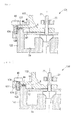
- an exhaust turbo supercharger 1 As shown in the vertical sectional view of FIG. 1 , an exhaust turbo supercharger 1 according to the present embodiment has a turbine housing 2 inside of which there is formed a spiral flow passage 2a, and a turbine wheel 3, which is provided in a substantially radial direction center section of this turbine housing 2.
- a turbine housing 2 Inside of which there is formed a spiral flow passage 2a, and a turbine wheel 3, which is provided in a substantially radial direction center section of this turbine housing 2.
- exhaust gas from an internal combustion engine (not shown in the drawing) is supplied.
- the turbine wheel 3 is rotation driven by exhaust gas supplied into this spiral flow passage 2a.
- material of the turbine wheel is generic heat resistant alloy.
- this exhaust turbo supercharger 1 has a compressor housing 12, inside of which there is formed a spiral flow passage 12a, and a compressor wheel 13 which is provided in a substantially radial direction center of the compressor housing 12.
- the compressor wheel 13 is rotation driven to take outside air into the compressor housing 12 and delivers the outside air that has been taken in, into the spiral flow passage 12a in the compressor housing 12.
- the spiral flow passage 12a of the compressor housing 12 is connected to an air intake system of the internal combustion engine. Accordingly, the outside air that has been delivered into this spiral flow passage 12a by the compressor wheel 13, is forcefully delivered to the air intake system of the internal combustion engine.
- the turbine wheel 3 and the compressor wheel 13 are linked by a turbine shaft 21.
- a bearing housing 22 is provided between the turbine housing 2 and the compressor housing 12.
- a bearing 23 that supports the turbine shaft 21, allowing it to rotate about the axis.
- a lubrication mechanism 24 that supplies lubricating oil to the bearing 23 to lubricate and cool the bearing 23.
- the bearing housing 22 is cooled by the lubricating oil supplied by this lubrication mechanism 24.
- the material of the bearing housing 22 is generally cast iron.
- variable nozzle mechanism 31 that adjusts the capacity of the turbine.
- the variable nozzle mechanism 31 has nozzle vanes 32 arranged on the inner circumference side of the spiral flow passage 2a in the turbine housing 2, in a plurality of positions at equal intervals in the circumferential direction of the turbine wheel 3.
- Each of the nozzle vanes 32 is provided on a ring shaped nozzle mount 33 attached to the turbine housing 2, and blade angles thereof (angle with respect to the radius line of the spiral flow passage 2a) can be respectively adjusted by the actuator 33.
- variable nozzle mechanism 31 adjusts the sectional area of the flow passage from the spiral flow passage to the turbine wheel 3 to adjust the flow speed of exhaust gas delivered to the turbine wheel 3.
- the rotation speed of the turbine wheel 3 is adjusted, and the volume of air delivered to the air intake system by the compressor wheel 13 can be adjusted.
- the turbine housing 2 and the bearing housing 22 are fixed, with the nozzle mount 33 sandwiched therebetween. That is to say, the turbine housing 2, the bearing housing 22, and a bolt 48, described later, serve also as fixing devices for fixing the nozzle mount 33.
- this exhaust turbo supercharger 1 because such a structure for fixing the nozzle mount 33 described above is employed, separate fixing devices for fixing the nozzle mount 33 need not be provided, and the number of parts can be reduced, lowering the production cost.
- FIG. 3 in order to facilitate understanding of the connection structure of the turbine housing 2 and the bearing housing 22, the shapes of the turbine housing 2 and the bearing housing 22 are drawn in simplified forms. Moreover, for the same reason, a supporting structure for the nozzle mount 33 is omitted from the drawing in FIG. 3 .
- a flange section 41 on the outer circumference of the bearing housing 22.
- a concave section 42 that houses the end to be connected with the turbine housing 2 of the bearing housing 22 along with the flange section 41.
- the internal diameter of the concave section 42 is substantially equal to the outer diameter of the flange section 41.
- a step section 43 that projects in the opening direction (bearing housing 22 side) of the concave section 42.
- step section 43 there is provided a gasket 44 that receives the flange section 41 of the bearing housing 22, to seal between the step section 43 and the bearing housing 22.
- the radial direction widths of the step section 43 and the gasket 44 are narrower than that of the flange section 41.
- a space S is formed around the entire circumference, between the flange section 41, the turbine housing 2 and the bearing housing 22.
- the bolt insert hole 46 is a blind hole. Inside this bolt insert hole 46 there is provided an internally threaded insert 47 made of heat insulating material. The material of the internally threaded insert 47 may be ceramic having a low level of thermal conductivity for example.
- the turbine housing 2 and the bearing housing 22 are detachably fixed by the internally threaded insert 47 that engages with the bolt 48. Specifically, the bearing housing 22 is fixed on the turbine housing 2 by the flange section 41 being clamped between the head section of the bolt 48 and the step section 43 of the turbine housing 2. A washer may be attached to the head section of the bolt 48 so that the flange section 41 is clamped between this washer and the step section 43 of the turbine housing 2.
- this exhaust turbo supercharger 1 since a reduction in the fastening force of the bolt 48 is unlikely to occur as described above, thereby ensuring the contact pressure of the gasket 44, the sealing capacity of the gasket 44 can be ensured without setting the fastening force of the bolt 48 high. As a result, this exhaust turbo supercharger 1 provides excellent workability in assembly and disassembly while effectively preventing exhaust gas that has flowed into between the turbine housing 2 and the bearing housing 22 from leaking to outside of the device.
- An exhaust turbo supercharger 51 according to the present embodiment is an exhaust turbo supercharger shown in the first embodiment, in which the structure for connecting the turbine housing 2 and the bearing housing 22 has been modified.
- a turbine housing 52 is used instead of the turbo housing 2.
- the turbine housing 52 is a turbine housing 2 as shown in the first embodiment, in which, instead of the blind bolt insert hole 46, there is provided a through hole 56 through which the bolt 48 is inserted.
- a gap is formed between the through hole 56 and the bolt 48.
- an air layer A to minimize the contact area between the bolt 48 and the turbine housing 2.
- an insert made from a heat insulating material, instead of the air layer A. Also in this case, since the insert prevents heat transmission between the turbine housing 2 and the bolt 48, a reduction in the fastening force of the bolt 48 is unlikely to occur so that the contact pressure of the gasket 44 is ensured, and therefore the sealing capacity of the gasket 44 can be ensured without setting the fastening force of the bolt 48 high.
- An exhaust turbo supercharger 61 according to the present embodiment is characterized mainly in that a turbine housing, 62 is used instead of the turbine housing 2 in the exhaust turbo supercharger 1 as shown in the first embodiment.
- the turbine housing 62 is a turbine housing 2 as shown in the first embodiment in which, instead of the bolt insert hole 46, there is provided a screw hole 66 with which the bolt 48 is engaged.
- heat radiating fins 67 are provided in the vicinity of the screw hole 66.
- an area in which the screw hole 66 is formed has a shape that projects toward the outer periphery, and in this area, a plurality of heat radiating fins 68 are arranged, extending in the axial direction of the screw hole 66, along the circumferential direction of the screw hole 66 at intervals.
- the heat radiating fins 67 are provided to increase the area of contact with the outside air. As a result, even if the temperature of the turbine housing 62 rises, in the vicinity of the screw hole 66 in the turbine housing 62, heat is effectively radiated to the surrounding area and the temperature rise is suppressed. As a result, a rise in temperature of the bolt 48 that engages with this screw hole 66 is suppressed, and a thermal expansion amount of the bolt 48 is reduced.
- a turbine housing 68 shown in FIG. 7 may be used instead of the turbine housing 66.
- the turbine housing 68 is a turbine housing 66 in which, instead of the heat radiating fins 67, there is provided a plurality of heat radiating grooves 69 that extend along the axial direction of the screw hole 66.
- FIG. 7 shows an example of providing V grooves as the heat radiating grooves 69.
- the shape of the heat radiating groove 69 is arbitrary. Also in this case, in the vicinity of the screw hole 66 in the turbine housing 68, heat is effectively radiated to the surrounding area and a rise in temperature can be suppressed.
- An exhaust turbo supercharger 71 according to the present embodiment is characterized mainly in that in the exhaust turbo supercharger 1 shown in the first embodiment, a turbine housing 72 is used instead of the turbine housing 2, and a bolt 76 is used instead of the bolt 48.
- a turbine housing 72 is used instead of the turbine housing 2
- a bolt 76 is used instead of the bolt 48.
- the same reference symbols are assigned to constructions similar to, or the same as, those in the first embodiment, and detailed descriptions thereof are omitted.
- the turbine housing 72 is a turbine housing 2 as shown in the first embodiment, in which there is provided a screw hole 77, instead of the bolt insert hole 46.
- the screw hole 77 is a blind hole, and on the bottom section of the screw hole 77, there is provided a through hole 77a that is concentric with the screw hole 77 and has a diameter smaller than that of the screw hole 77.
- the bolt 76 is a bolt 48 as shown in the first embodiment, in which there is formed a through hole 76a along the axis of the bolt 76.
- the through hole 76a is formed along the axial direction. Accordingly, the surface area of the bolt 76 is increased and the amount of heat radiated from the bolt 76 increases, while the bolt 76 is cooled down by outside air that flows into the through hole 76a.
- the through hole 77a is provided in the area on the bottom section of the screw hole 77 which opposes to the through hole 76a of the bolt 76. Accordingly, since outside air travels through the through hole 76a of the bolt 76 more easily, the temperature rise in the bolt 76 becomes further unlikely to occur.
- the screw hole provided in the turbine housing may be a through hole. In this case too, since outside air travels through the through hole 76a of the bolt 76 more easily, the temperature rise in the bolt 76 becomes further unlikely to occur.
- An exhaust turbo supercharger 81 according to the present embodiment is characterized mainly in that in the exhaust turbo supercharger 1 as shown in the first embodiment, a turbine housing 82 is used instead of the turbine housing 2.
- a turbine housing 82 is used instead of the turbine housing 2.
- the turbine housing 82 is a turbine housing 2 as shown in the first embodiment, in which there is provided a screw hole 86, instead of the bolt insert hole 46.
- the screw hole 86 is a blind hole.
- a heat shield layer 88 made from a heat insulating material is formed on the inner surface of the turbine housing 82.
- the heat shield layer 88 is formed in the turbine housing 82, in the area of the inner surface of the spiral flow passage 2a and from the spiral flow passage 2a to the vicinity of the outer periphery of the turbine wheel.
- heat shield layer 88 for example, a heat shield coating film made from a sprayed film of Co-Ni-Cr-Al-Y alloy or the like may be used. Furthermore, as the heat shield layer 88, a thin-walled heat shield tube, the outer shape of which substantially corresponds to the inner surface shape of the spiral flow passage 2a may be provided. As this heat shield tube, for example, a stainless steel tube or ceramic tube having a low level of thermal conductivity, may be used.
- the heat shield layer 88 provided on the inner surface of the turbine housing 82 prevents heat transmission from the exhaust gas introduced into the turbine housing 82 to the turbine housing 82.
- a temperature increase of the turbine housing 82 can be suppressed, and the thermal expansion amount of the turbine housing 82 and the bolt 48 that engages with the turbine housing 82 is reduced. Therefore, a decrease in the fastening force of the bolt 48 is unlikely to occur, so that the contact pressure of the gasket 44 can be ensured.
- An exhaust turbo supercharger 91 according to the present embodiment is characterized mainly in that in the exhaust turbo supercharger 1 as shown in the first embodiment, a turbine housing 92 is used instead of the turbine housing 2, and a bearing housing 93 is used instead of the bearing housing 22.
- a turbine housing 92 is used instead of the turbine housing 2
- a bearing housing 93 is used instead of the bearing housing 22.
- the turbine housing 92 is a turbine housing 2 as shown in the first embodiment, in which the concave section 42 is formed to have diameter smaller than the flange section 41 of the bearing housing 93, a flange section 92a is provided on an end that connects to the bearing housing 93, and instead of the bolt insert hole 46, a through hole 92b that passes through the flange section 92a in the thickness direction, is provided in the flange section 92a.
- the gasket 44 is interposed between: the area between the area in which the through hole 92b is formed and the concave section 42, and the flange section 41 of the bearing housing 93.
- the bearing housing 93 is one where, in the bearing housing 22, a screw hole 93a is provided in the flange section 41.
- the screw hole 93a is provided in the bearing housing 92, in which a temperature rise is less likely to occur compared to the turbine housing 93 that comes in contact with exhaust gas, and the turbine housing 92 and the bearing housing 93 are connected by the bolt 48 that engages with this screw hole 93a.
- the thread face which is the largest area that comes in contact with other members, is brought in contact with the bearing housing 93, in which a temperature rise is unlikely to occur.
- the exhaust turbo supercharger 101 according to the present embodiment is characterized mainly in that in the exhaust turbo supercharger 1 as shown in the first embodiment, a turbine housing 102 is used instead of the turbine housing 2, and between the head section of the bolt 48 and the flange section 41 of the bearing housing 22, there is provided an elastic member 104 in a state of being compressed in the axial direction of the bolt 48.
- a turbine housing 102 is used instead of the turbine housing 2
- an elastic member 104 in a state of being compressed in the axial direction of the bolt 48.
- the turbine housing 102 is a turbine housing 2 as shown in the first embodiment, in which there is provided a screw hole 106, instead of the bolt insert hole 46.
- the screw hole 106 is a blind hole.
- a conical spring washer is used as the elastic member 104.
- the elastic member 104 is not limited to this, and for example, other types of spring or bush made from rubber or resin having elasticity may be used.
- the elastic member 104 is provided in a state of being compressed in the axial direction of the bolt 48.
- the elastic member 104 returns from its compressed state by this difference amount, thereby compensating for the difference between these thermal expansion amounts. Therefore, a decrease in the fastening force of the bolt 48 is unlikely to occur, so that the contact pressure of the gasket 44 is ensured.
- a washer 107 made from a material having a thermal expansion coefficient higher than that of the bearing housing 22 may be provided.
- the material of the washer 107 for example, Cu (copper) or Cu-base alloy, Al (aluminum) or Al-base alloy, or Mg (magnesium) based alloy may be used.
- An exhaust turbo supercharger 111 according to the present embodiment is characterized mainly in that, in the exhaust turbo supercharger 1 as shown in the first embodiment, the turbine housing 102 as shown in the seventh embodiment is used instead of the turbine housing 2, and a bearing housing 113 is used instead of the bearing housing 22.
- the same reference symbols are assigned to constructions similar to, or the same as, those in the first embodiment, and detailed descriptions thereof are omitted.
- the bearing housing 113 is such that a bolt support section 114 that receives the bolt 48 can elastically deform in the axial direction of the bolt 48.
- the bearing housing 113 has a slit 116 provided at least on the outer circumference surface of the area in the flange section 41 that receives the bolt 48, thereby enabling the bolt support section 114 to be such that the area that receives the bolt 48 of the flange section 41 can elastically deform in the axial direction of the bolt 48.
- the bolt support section 114 receives the bolt 48 in a state of being elastically deformed to the turbine housing 102 side.
- the bolt support section 114 of the bearing housing 113 receives the bolt 48 in a state of being elastically deformed to the turbine housing 102 side.
- the bolt support section 114 returns by that amount in the direction reducing the amount of its elastic deformation, thereby compensating for the difference between these thermal expansion amounts. Therefore, a decrease in the fastening force of the bolt 48 is unlikely to occur, so that the contact pressure of the gasket 44 is ensured.
- An exhaust turbo supercharger 121 according to the present embodiment is characterized mainly in that, in the exhaust turbo supercharger 1 as shown in the first embodiment, a turbine housing 122 is used instead of the turbine housing 2, and a bearing housing 123 is used instead of the bearing housing 22.
- a turbine housing 122 is used instead of the turbine housing 2
- a bearing housing 123 is used instead of the bearing housing 22.
- the turbine housing 122 is a turbine housing 2 as shown in the first embodiment, in which a screw hole 126 is provided instead of the bolt insert hole 46, and in which there is provided on the step section 43, a cylindrical male engaging section 127 that surrounds the turbine shaft 21.
- the screw hole 126 is a blind hole.
- the bearing housing 123 is a bearing housing 123 as shown in the first embodiment, in which, on the side of the flange section 41 facing the step section 41, there is provided a female engaging section 128 into which the male engaging section 127 is inserted, the inner circumference surface of which engages with this male engaging section 127.
- the turbine housing 122 and the bearing housing 123 are detachably fixed by the bolt 48, which engages with the screw hole 126 in a state where the male engaging section 127 and the female engaging section 128 are engaged with each other.
- the male engaging section 127 provided in the turbine housing 122 thermal-expands toward the radial direction outside.
- the bearing housing 123 is cooled down by the lubrication mechanism 24 as mentioned above, the thermal expansion amount of the female engaging section 128 provided in the bearing housing 123 toward the radial direction outside is smaller than the thermal expansion amount of the male engaging section 127 toward the radial direction outside.
- the outer circumference surface of the male engaging section 127 comes into tight contact with the inner circumference surface of the female engaging section 128, sealing between the turbine housing 122 and the bearing housing 123.
- Adhesion between the male engaging section 127 and the female engaging section 128 becomes stronger as the difference between the thermal expansion amounts of the male engaging section 127 and the female engaging section 128 (in other words, the difference between the thermal expansion amounts of the turbine housing 122 and the bearing housing 123) increases, and the sealing property between the turbine housing 122 and the bearing housing 123 becomes more reliable by the amount of this increase.
- FIG. 15 shows an exhaust turbo supercharger 131 as an example of an installation form of the male engaging section 127 and the female engaging section 128.
- the exhaust turbo supercharger 131 is an exhaust turbo supercharger 121 in which a turbine housing 132 is used instead of the turbine housing 122, and a bearing housing 133 is used instead of the bearing housing 123.
- the turbine housing 132 is a turbine housing 122 in which the inner diameter thereof is smaller than the flange section 41 of the bearing housing 133, and the step section 43 is omitted.
- the gasket 44 is interposed between: the area between the area in which the screw hole 126 is formed and the concave section 42, and the flange section 41 of the bearing housing 133.
- the outer periphery thereof constructs the male engaging section 127.
- the bearing housing 133 is a turbine housing 123, in which the flange section 41 is made to project from the outer periphery of the turbine housing 132 toward the radial direction outside, and in which on this flange section 41, there is provided a through hole 134 into which the bolt 48 is inserted, and the female engaging section 128 is provided in the area on the radial direction outside of the outer periphery of the turbine housing 132.
- An exhaust turbo supercharger 141 according to the present embodiment is characterized mainly in that, in the exhaust turbo supercharger 1 as shown in the first embodiment, a turbine housing 142 is used instead of the turbine housing 2.
- a turbine housing 142 is used instead of the turbine housing 2.
- the turbine housing 142 has the construction of the turbine housing 2 as shown in the first embodiment, in which a screw hole 144 is provided instead of the bolt insert hole 46, and in the concave section 42 there is provided a substantially cylindrical projection section 148, the tip end of which is inserted into the bearing housing 22.
- the narrow section 146 is formed between the projection section 148 and the tip end of the bearing housing 22, and the expanded section 147 is formed in the area on the radial direction outside of the projection section 148, within the concave section 43.
- the narrow section 146 serves as an aperture that reduces the pressure of exhaust gas flowed in from an insertion passage section for the turbine shaft 21 in the turbine housing 142, to between the turbine housing 142 and the bearing housing 22.
- the exhaust gas that has passed through the narrow section 146 expands by flowing into the expanded section 147 reducing the pressure thereof.
- the pressure applied by the exhaust gas on the gasket 44 can be low. Therefore, even if a difference in the thermal expansion amounts between the turbine housing 142 and the bolt 48, and the bearing housing 22 occurs, and the fastening force of the bolt 48 decreases, leakage of exhaust gas from between the turbine housing 142 and the bearing housing 22 is prevented.
- An exhaust turbo supercharger 151 according to the present embodiment is characterized mainly in that, in the exhaust turbo supercharger 141 as shown in the tenth embodiment, a turbine housing 152 is used instead of the turbine housing 142.
- a turbine housing 152 is used instead of the turbine housing 142.
- the same reference symbols are assigned to constructions similar to, or the same as, those in the tenth embodiment, and detailed descriptions thereof are omitted.
- the turbine housing 152 is a turbine housing 142 as shown in the tenth embodiment, in which there is provided a bypass flow passage 154 that continues from the expanded section 147 to the vicinity of an exhaust gas exit 152a.
- a bypass flow passage 154 that continues from the expanded section 147 to the vicinity of an exhaust gas exit 152a.
- the pressure of the exhaust gas within the expanded section 147 is greater than the pressure of the exhaust gas in the vicinity of the exhaust gas exit 152a of the turbine housing 152
- the exhaust gas within the expanded section 147 travels through the bypass flow passage 154 and flows into the vicinity of the exhaust gas exit 152a of the turbine housing 152, reducing the inner pressure of the expanded section 147. Therefore, in this exhaust turbo supercharger 151, the pressure applied by the exhaust gas to the gasket 44 becomes low, and the sealing capacity of the gasket 44 can be ensured.
Landscapes
- Engineering & Computer Science (AREA)
- Chemical & Material Sciences (AREA)
- Combustion & Propulsion (AREA)
- Mechanical Engineering (AREA)
- General Engineering & Computer Science (AREA)
- Chemical Kinetics & Catalysis (AREA)
- General Chemical & Material Sciences (AREA)
- Supercharger (AREA)
Abstract
Description
- The present invention relates to an exhaust turbo supercharger to be used in an internal combustion engine that serves as a power source in a vessel, motor vehicle or power generator, in particular, to a VG (variable geometry) type exhaust turbo supercharger.
- An exhaust turbo supercharger improves the combustion efficiency of an internal combustion engine by forcefully supplying air into a combustion chamber of the internal combustion engine to improve output of the internal combustion engine and improve the properties of exhaust gas of the internal combustion engine.
As such an exhaust turbo supercharger, a variable displacement type exhaust turbo supercharger disclosed inPatent Document 1 mentioned later is commonly known for example. - This variable displacement type exhaust turbo supercharger has a turbine housing (turbine casing), inside of which there is formed a spiral flow passage, and a turbine wheel provided substantially in the center in the radial direction of this turbine housing. Exhaust gas from an internal combustion engine is supplied into the spiral flow passage of the turbine housing. The turbine wheel is rotation driven by exhaust gas supplied into this spiral flow passage.
- Moreover, this variable displacement type exhaust turbo supercharger has a compressor housing, inside of which there is formed a spiral flow passage, and a compressor wheel provided in a substantially radial direction center of the compressor housing. The compressor wheel is rotation driven to take outside air into the compressor housing and deliver the outside air that has been taken in into the spiral flow passage in the compressor housing. The spiral flow passage of the compressor is connected to an air intake system of the internal combustion engine. Accordingly, the outside air that has been delivered into this spiral flow passage by the compressor wheel is forcefully delivered to the air intake system of the internal combustion engine.
- The turbine wheel and the compressor wheel are linked by a turbine shaft. A bearing housing is provided between the turbine housing and the compressor housing. In the bearing housing, there is provided a bearing that supports the turbine shaft, allowing it to rotate around the axis.
In the bearing housing, on the outer circumference section of an end to be connected with the turbine housing, there is provided a flange section. In the turbine housing, on an end to be connected with the bearing housing, there is formed a plurality of screw holes on the outside of the area that receives the flange section of the bearing housing. The bearing housing and the turbine housing are connected by engaging a bolt in each of the screw holes provided in the turbine housing. Specifically, the bearing housing is fixed on the turbine housing by the flange section of the bearing housing being pressed against the turbine housing by the head sections of the bolts that engage with each of the screw holes of the turbine housing, or by washers attached to the bolt head sections.
Moreover, between the turbine housing and the bearing housing, there is provided a gasket that prevents exhaust gas that has flowed through an insert section of the turbine shaft into between the turbine housing and the bearing housing from leaking to outside of the device. The contact pressure contact pressure of this gasket with the turbine housing and the bearing housing is determined by the fastening force of the bolts. - In this variable displacement type exhaust turbo supercharger, exhaust gas introduced from an exhaust system of the internal combustion engine into the spiral flow passage in the turbine housing rotation-drives the turbine wheel.
As the turbine wheel is rotation driven in this manner, this driving force is transmitted to the compressor wheel via the turbine shaft, and the compressor wheel is thereby rotation driven.
Thus, the compressor wheel takes outside air into the compressor housing and delivers the outside air that has been taken in into the spiral flow passage in the compressor housing. As a result, the outside air that has been taken into the compressor housing is forcefully supplied into a combustion chamber of the internal combustion engine. - Furthermore, in this variable displacement type exhaust turbo supercharger, in the turbine housing, there is provided a variable nozzle mechanism for adjusting the displacement of the turbine.
The variable nozzle mechanism has nozzle vanes arranged on the inner circumference side of the spiral flow passage in the turbine housing in a plurality of positions at equal intervals in the circumferential direction of the turbine. Each of the nozzle vanes is provided so as to be able to respectively change the blade angle thereof with respect to a nozzle mount attached to the turbine housing.
The variable nozzle mechanism is to adjust a flow speed of exhaust gas delivered from the spiral flow passage into the turbine housing by adjusting the blade angle of each of the nozzle vanes. In the variable nozzle mechanism, by adjusting the flow speed of exhaust gas delivered to the turbine wheel in this manner, the rotation speed of the turbine wheel is adjusted, and the volume of air delivered to the air intake system by the compressor wheel can be adjusted. -
- Patent Document 1: Japanese Unexamined Patent Application, Publication No.
2004-156592 - While operating the variable displacement type exhaust turbo supercharger, the turbine housing reaches a high temperature as it receives heat of the exhaust gas traveling inside. Moreover, since the thread face of the bolt that engages with the screw hole of the turbine housing is in surface contact with the turbine housing, the temperature of this bolt becomes high.
On the other hand, in the bearing housing, usually there is provided a lubrication mechanism that supplies lubricating oil to the bearing to lubricate and cool the bearing. The bearing housing is cooled down by lubricating oil supplied from the lubrication mechanism and a temperature rise therein is unlikely to occur compared to the turbine housing.
Therefore, the thermal expansion amount of the bearing housing as a result of operating the variable displacement type exhaust turbo supercharger is smaller than the thermal expansion amount of the turbine housing and the bolt. Accordingly, while operating the variable displacement type exhaust turbo supercharger, the fastening force of the bolt for fastening the turbine housing and the bearing housing decreases, and the contact pressure of the gasket decreases. - Conventionally, in order to sufficiently ensure the contact pressure of the gasket even during operation of the variable displacement type exhaust turbo supercharger, in consideration of a reduction amount in fastening force of the bolt mentioned above, the fastening torque of the bolt is set higher than the torque required for simple fixation.
However, in the case where the bolt fastening torque is set higher, a longer period of time is required for detaching and attaching the bolt, resulting in a low level of workability in assembly and disassembly of the variable displacement type exhaust turbo supercharger. - Here, in the variable displacement type exhaust turbo supercharger, the turbine housing and the bearing housing are fixed with the nozzle mount sandwiched therebetween. In other words, the turbine housing, the bearing housing, and the bolt serve also as fixing devices for fixing the nozzle mount.
In this construction it is not necessary to separately provide a fixation device for fixing the nozzle mount. As a result, the number of parts is reduced and production cost is reduced. - However, in such a construction where the nozzle mount is clamped and fixed between the turbine housing and the bearing housing, the fastening force of the bolt acts not only as force to fix the turbine housing and the bearing housing but also as force for the turbine housing and the bearing housing to retain the nozzle mount. In other words, in this construction, since the fastening force of the bolt is distributed, more reliable fixation of the turbine housing and the bearing housing using the bolt is required.
- The present invention takes the above circumstances into consideration, and its object is to provide an exhaust turbo supercharger that is able to effectively prevent exhaust gas that has flowed into between the turbine housing and the bearing housing from leaking to outside of the device, while also providing an excellent level of workability in assembly and disassembly.
- In order to solve above problems, the present invention provides following means.
A first aspect of the present invention provides an exhaust turbo supercharger having: a turbine housing, into which exhaust gas from an internal combustion engine is introduced; a turbine wheel which is provided within the turbine housing and which is rotation-driven by the exhaust gas; a turbine shaft, one end of which is inserted into the turbine housing, and to which the turbine wheel is attached; a bearing which supports the turbine shaft; a bearing housing which is connected to the turbine housing and inside of which the bearing is housed; and a gasket which seals, in an area outside in the radial direction of the turbine shaft, between the turbine housing and the bearing housing; wherein a bolt insert hole is formed in the turbine housing, an internal thread insert made from a heat insulating material is provided in the bolt insert hole, and the turbine housing and the bearing housing are detachably fixed by a bolt that engages with the internal thread insert. - In the exhaust turbo supercharger according to the first aspect of the present invention mentioned above, heat transmission between the turbine housing and the bolt is prevented by the internal thread insert made from a heat insulating material that is provided in the bolt insert hole of the turbine housing.
As a result, even if the temperature of the turbine housing rises while operating the exhaust turbo supercharger, since the temperature rise in the bolt is suppressed, and the thermal expansion amount of the bolt is reduced, a reduction in the fastening force of the bolt is unlikely to occur.
In this exhaust turbo supercharger, since a reduction in the fastening force of the bolt is unlikely to occur as described above, thereby ensuring the contact pressure of the gasket, the sealing capacity of the gasket can be ensured without setting the fastening force of the bolt high. - A second aspect of the present invention provides an exhaust turbo supercharger having: a turbine housing into which exhaust gas from an internal combustion engine is introduced; a turbine wheel which is provided within the turbine housing and which is rotation-driven by the exhaust gas; a turbine shaft, one end of which is inserted into the turbine housing, and to which the turbine wheel is attached; a bearing which supports the turbine shaft; a bearing housing which is connected to the turbine housing and inside of which the bearing is housed; and a gasket which seals, in an area outside in the radial direction of the turbine shaft, between the turbine housing and the bearing housing; wherein a through hole is formed in the turbine housing, the turbine housing and the bearing housing are detachably fixed by a bolt inserted into the through hole, and a nut that engages with the bolt; and an insert made from a heat insulating material, or an air layer, is provided between an inner surface of the through hole and the bolt.
- In the exhaust turbo supercharger according to the second aspect of the present invention, between the inner surface of the through hole of the turbine housing and the bolt, there is formed the insert made from a heat insulating material, or the air layer, and this insert or air layer prevents heat transmission between the turbine housing and the bolt.
As a result, even if the temperature of the turbine housing rises while operating the exhaust turbo supercharger, since the temperature rise in the bolt is suppressed, and the thermal expansion amount of the bolt is reduced, a reduction in the fastening force of the bolt is unlikely to occur.
In this exhaust turbo supercharger, since a reduction in the fastening force of the bolt is unlikely to occur as described above, thereby ensuring the contact pressure of the gasket, the sealing capacity of the gasket can be ensured without setting the fastening force of the bolt high. - Moreover, a third aspect of the present invention provides an exhaust turbo supercharger having: a turbine housing into which exhaust gas from an internal combustion engine is introduced; a turbine wheel which is provided within the turbine housing and which is rotation-driven by the exhaust gas; a turbine shaft, one end of which is inserted into the turbine housing, and to which the turbine wheel is attached; a bearing which supports the turbine shaft; a bearing housing which is connected to the turbine housing and inside of which the bearing is housed; and a gasket which seals, in an area outside in the radial direction of the turbine shaft, between the turbine housing and the bearing housing; wherein a screw hole is formed in the turbine housing, heat radiating fins or heat radiating grooves are formed in the vicinity of the screw hole, and the turbine housing and the bearing housing are detachably fixed by a bolt that engages with the screw hole.
- In the exhaust turbo supercharger according to the third aspect of the present invention, in the vicinity of the screw hole of the turbine housing, heat radiating fins or heat radiating grooves are provided to increase the area in contact with the outside air.
Therefore, even if the temperature of the turbine housing rises while operating the exhaust turbo supercharger, in the vicinity of the screw hole in the turbine housing, heat is effectively radiated to the surrounding area and the temperature rise is suppressed.
As a result, temperature rise in the bolt that engages with this screw hole is suppressed, and the thermal expansion amount of the bolt is reduced. Therefore, the fastening force of the bolt is unlikely to decrease.
In this exhaust turbo supercharger, since a reduction in the fastening force of the bolt is unlikely to occur as described above, thereby ensuring the contact pressure of the gasket, the sealing capacity of the gasket can be ensured without setting the fastening force of the bolt high. - Moreover, a fourth aspect of the present invention provides an exhaust turbo supercharger having: a turbine housing into which exhaust gas from an internal combustion engine is introduced; a turbine wheel which is provided within the turbine housing and which is rotation-driven by the exhaust gas; a turbine shaft, one end of which is inserted into the turbine housing, and to which the turbine wheel is attached; a bearing which supports the turbine shaft; a bearing housing which is connected to the turbine housing and inside of which the bearing is housed and a gasket which seals, in an area outside in the radial direction of the turbine shaft, between the turbine housing and the bearing housing; wherein there is formed a screw hole in the turbine housing; the turbine housing and the bearing housing are detachably fixed by a bolt that engages with the screw hole; and a through hole is provided in the bolt along the axis of the bolt.
- In the exhaust turbo supercharger according to the fourth aspect of the present invention, on the bolt for fixing the turbine housing and the bearing housing, a through hole is formed along the axial direction.
As a result, the surface area of the bolt is increased and the amount of heat radiated from the bolt increases, while the bolt is cooled down by outside air that flows into the through hole.
As a result, even if the temperature of the turbine housing rises while operating the exhaust turbo supercharger, since the temperature rise in the bolt is suppressed, and the thermal expansion amount of the bolt is reduced, a reduction in the fastening force of the bolt is unlikely to occur.
In this exhaust turbo supercharger, since a reduction in the fastening force of the bolt is unlikely to occur as described above, thereby ensuring the contact pressure of the gasket, the sealing capacity of the gasket can be ensured without setting the fastening force of the bolt high.
In this exhaust turbo supercharger, the screw hole provided in the turbine housing may be a through hole, or, in the case of a blind screw hole, in the bottom section of this screw hole a through hole in the area that opposes to a through hole in a bolt may be provided. In this case, since outside air can more easily flow through inside the bolt through the hole, a temperature rise in the bolt becomes more unlikely to occur, and a reduction in the contact pressure on the gasket due to thermal expansion of the bolt can be effectively prevented. - Moreover, a fifth aspect of the present invention provides an exhaust turbo supercharger having: a turbine housing into which exhaust gas from an internal combustion engine is introduced; a turbine wheel which is provided within the turbine housing and which is rotation-driven by the exhaust gas; a turbine shaft, one end of which is inserted into the turbine housing, and to which the turbine wheel is attached; a bearing which supports the turbine shaft; a bearing housing which is connected to the turbine housing and inside of which the bearing is housed; and a gasket which seals, in an area outside in the radial direction of the turbine shaft, between the turbine housing and the bearing housing; wherein a screw hole is formed in the turbine housing; the turbine housing and the bearing housing are detachably fixed by a bolt that engages with the screw hole; and on an inner surface of the turbine housing in an area in contact with the exhaust gas, a heat shield layer is formed.
- In the exhaust turbo supercharger according to the fifth aspect of the present invention, the heat shield layer provided on the inner surface of the turbine housing prevents heat transmission from the exhaust gas that has been introduced into the turbine housing, to the turbine housing.
As a result, even while operating the exhaust turbo supercharger, temperature rise in the turbine housing is suppressed, and the thermal expansion amounts of the turbine housing and the bolt that engages with the turbine housing are reduced. As a result, the fastening force of the bolt is unlikely to decrease.
In this exhaust turbo supercharger, since a reduction in the fastening force of the bolt is unlikely to occur as described above, thereby ensuring the contact pressure of the gasket, the sealing capacity of the gasket can be ensured without setting the fastening force of the bolt high.
Moreover, in this exhaust turbo supercharger, since the heat shielding capacity of the turbine housing is improved, the efficiency of the turbine can be improved.
Furthermore, in this exhaust gas turbo supercharger, since temperature rise in the turbine housing can be suppressed, the load on the turbine housing due to heat stress can be reduced and the durability of the turbine housing can be improved. - Moreover, a sixth aspect of the present invention provides an exhaust turbo supercharger having: a turbine housing into which exhaust gas from an internal combustion engine is introduced; a turbine wheel which is provided within the turbine housing and which is rotation-driven by the exhaust gas; a turbine shaft, one end of which is inserted into the turbine housing, and to which the turbine wheel is attached; a bearing which supports the turbine shaft; a bearing housing which is connected to the turbine housing and inside of which the bearing is housed; and a gasket which seals, in an area outside in the radial direction of the turbine shaft, between the turbine housing and the bearing housing; wherein a screw hole is formed in the bearing housing, and the turbine housing and the bearing housing are detachably fixed by a bolt that engages with the screw hole.
- In the exhaust turbo supercharger according to the sixth aspect of the present invention mentioned above, the screw hole is provided in the bearing housing, where the temperature is unlikely to rise, and the turbine housing and the bearing housing are connected by the bolt that engages with the screw hole.
In other words, in the bolt that connects the turbine housing and the bearing housing, the thread face, which is the largest area that comes in contact with other members, is brought in contact with the bearing housing, in which a temperature rise is unlikely to occur.
Therefore, in this exhaust turbo supercharger, even while operating the exhaust turbo supercharger, the heat of the turbine housing is unlikely to be transmitted to the bolt, and thermal expansion amount of the bolt is reduced. As a result, the fastening force of the bolt is unlikely to decrease.
In this exhaust turbo supercharger, since a reduction in the fastening force of the bolt is unlikely to occur as described above, thereby ensuring the contact pressure of the gasket, the sealing capacity of the gasket can be ensured without setting the fastening force of the bolt high.
Moreover, in this exhaust turbo supercharger, since the head section of the bolt faces the turbine housing side (end section side of the exhaust turbo supercharger), tools (such as a spanner) can easily enter in the vicinity of the head section of the bolt, enabling easy operation of attaching and detaching the bolt. - Moreover, a seventh aspect of the present invention provides an exhaust turbo supercharger having: a turbine housing, into which exhaust gas from an internal combustion engine is introduced; a turbine wheel which is provided within the turbine housing and which is rotation-driven by the exhaust gas; a turbine shaft, one end of which is inserted into the turbine housing, and to which the turbine wheel is attached; a bearing which supports the turbine shaft; a bearing housing which is connected to the turbine housing and inside of which the bearing is housed; and a gasket which seals, in an area outside in the radial direction of the turbine shaft, between the turbine housing and the bearing housing; wherein a screw hole is formed in the turbine housing; the turbine housing and the bearing housing are detachably fixed by a bolt that engages with the screw hole; and between a head section of the bolt and the bearing housing there is provided an elastic member in a state of being compressed in the axial direction of the bolt.
- In the exhaust turbo supercharger according to the seventh aspect of the present invention, between the bolt and the bearing housing there is provided the elastic member in a state of being compressed in the axial direction of the bolt.
As a result, when a difference occurs between the thermal expansion amounts of the turbine housing and the bolt and the thermal expansion amount of the bearing housing, the elastic member returns from its compressed state by this difference amount, thereby compensating for the difference between these thermal expansion amounts. Therefore, a decrease in the fastening force of the bolt is unlikely to occur.
In this exhaust turbo supercharger, since a reduction in the fastening force of the bolt is unlikely to occur as described above, thereby ensuring the contact pressure of the gasket, the sealing capacity of the gasket can be ensured without setting the fastening force of the bolt high.
Here, as the elastic member, for example, a spring such as a conical spring washer or a bush made from rubber or resin having elasticity may be used. - Moreover, an eighth aspect of the present invention provides an exhaust turbo supercharger having: a turbine housing into which exhaust gas from an internal combustion engine is introduced; a turbine wheel which is provided within the turbine housing and which is rotation-driven by the exhaust gas; a turbine shaft, one end of which is inserted into the turbine housing, and to which the turbine wheel is attached; a bearing which supports the turbine shaft; a bearing housing which is connected to the turbine housing and inside of which the bearing is housed; and a gasket which seals, in an area outside in the radial direction of the turbine shaft, between the turbine housing and the bearing housing; wherein a screw hole is formed in the turbine housing, the turbine housing and the bearing housing are detachably fixed by a bolt that engages with the screw hole, and in the bearing housing, a bolt support section that receives the bolt is able to elastically deform in the axial direction of the bolt, and the bolt support section receives the bolt in a state of being elastically deformed to the turbine housing side.
- In the exhaust turbo supercharger according to the eighth aspect of the present invention, in the bearing housing, the bolt support section that receives the bolt is able to elastically deform in the axial direction of the bolt.
This bolt support section receives the bolt in a state of being elastically deformed toward the turbine housing side.
As a result, when a difference occurs between the thermal expansion amounts of the turbine housing and the bolt, and thermal expansion amount of the bearing housing, the bolt support section returns by this amount in the direction that reduces its elastic deformation, thereby compensating for the difference between these thermal expansion amounts. Therefore, a decrease in the fastening force of the bolt is unlikely to occur.
In this exhaust turbo supercharger, since a reduction in the fastening force of the bolt is unlikely to occur as described above, thereby ensuring the contact pressure of the gasket, the sealing capacity of the gasket can be ensured without setting the fastening force of the bolt high. - Moreover, a ninth aspect of the present invention provides an exhaust turbo supercharger having: a turbine housing into which exhaust gas from an internal combustion engine is introduced; a turbine wheel which is provided within the turbine housing and which is rotation-driven by the exhaust gas; a turbine shaft, one end of which is inserted into the turbine housing, and to which the turbine wheel is attached; a bearing which supports the turbine shaft; a bearing housing which is connected to the turbine housing and inside of which the bearing is housed; and a gasket which seals, in an area outside in the radial direction of the turbine shaft, between the turbine housing and the bearing housing; wherein a screw hole is formed in the turbine housing, in the turbine housing a cylindrical male engaging section that surrounds the turbine shaft is provided, in the bearing housing there is provided a female engaging section into which the male engaging section is inserted, an inner surface of which is fitted together with the male engaging section, and the turbine housing and the bearing housing are detachably fixed by a bolt that engages with the screw hole, in a state where the male engaging section and the female engaging section are fitted together.
- Here, as mentioned above, even while operating the exhaust turbo supercharger, the temperature of the bearing housing is unlikely to rise compared to the turbine housing, and the thermal expansion amount of the bearing housing is smaller than that of the turbine housing.
In the exhaust turbo supercharger according to the ninth aspect of the present invention, the male engaging section is provided in the turbine housing, and in the bearing housing there is provided the female engaging section that is fitted together with the male engaging section (so called spigot coupling).
Accordingly, when operating this exhaust turbo supercharger, the temperature of the turbine housing rises, and the male engaging section provided in the turbine housing also thermal-expands toward the radial direction outside.
On the other hand, the thermal expansion amount of the female engaging section provided in the bearing housing is smaller than that of the male engaging section. As a result, when the temperature of the turbine housing rises, the outer circumference surface of the male engaging section comes in tight contact with the inner circumference surface of the female engaging section, sealing between the turbine housing and the bearing housing. Adhesion between the male engaging section and the female engaging section becomes stronger as the difference between the thermal expansion amounts of the male engaging section and the female engaging section (in other words, the difference between the thermal expansion amounts of the turbine housing and the bearing housing) increases, and the sealing property between the turbine housing and the bearing housing becomes more reliable.
As a result, even if a difference occurs between the thermal expansion amounts of the turbine housing and the bolt, and the bearing housing, so that the fastening force of the bolt decreases, leakage of exhaust gas from between the turbine housing and the bearing housing is prevented.
Therefore, in this exhaust turbo supercharger, sealing capacity of the gasket can be ensured without setting the fastening force of the bolt high. - Moreover, a tenth aspect of the present invention provides an exhaust turbo supercharger having: a turbine housing into which exhaust gas from an internal combustion engine is introduced; a turbine wheel which is provided within the turbine housing and which is rotation-driven by the exhaust gas; a turbine shaft, one end of which is inserted into the turbine housing, and to which the turbine wheel is attached; a bearing which supports the turbine shaft; a bearing housing which is connected to the turbine housing and inside of which the bearing is housed; and a gasket which seals, in an area outside in the radial direction of the turbine shaft, between the turbine housing and the bearing housing; wherein a screw hole is formed in the turbine housing, and between the turbine housing and the bearing housing, there are provided in the following order toward the radial direction outside of the turbine shaft: a narrow section in which a distance between the turbine housing and the bearing housing is short; and an expanded section in which a distance between the turbine housing and the bearing housing is greater than that in the narrow section; and the turbine housing and the bearing housing are detachably fixed by a bolt that engages with the screw hole.
- In the exhaust turbo supercharger according to the tenth aspect of the present invention mentioned above, between the turbine housing and the bearing housing there are provided the narrow section and the expanded section, in that order toward the gasket.
The narrow section serves as an aperture that reduces the pressure of exhaust gas flowed in from an insertion passage section of the turbine shaft of the turbine housing to between the turbine housing and the bearing housing.
The exhaust gas that has passed through the narrow section expands when flowing into the expanded section, reducing the pressure thereof.
As described, in this exhaust turbo supercharger, the pressure applied by exhaust gas on the gasket can be low. Therefore, even if a difference in the thermal expansion amounts between the turbine housing and the bolt, and the bearing housing occurs, and the fastening force of the bolt decreases, leakage of exhaust gas from between the turbine housing and the bearing housing is prevented.
In particular, in the case where the pressure variation of the exhaust gas is significant, leakage of exhaust gas from between the turbine housing and the bearing housing can be effectively prevented.
Specifically, as the exhaust gas that has entered between the turbine housing and the bearing housing passes through the narrow section, a time difference occurs in the pressure variance with the exhaust gas within the turbine housing.
As a result, in the expanded section, the pressure of exhaust gas is averaged and the inner pressure of the expanded section becomes lower than the peak pressure of the exhaust gas.
Therefore, in this exhaust turbo supercharger, sealing capacity of the gasket can be ensured without setting the fastening force of the bolt high. - Here, in the exhaust turbo supercharger according to the tenth aspect mentioned above, in the turbine housing, there may be provided a bypass flow passage that continues from the expanded section to the vicinity of an exit of the exhaust gas.
Since almost all the energy of the exhaust gas that has been introduced into the turbine housing is consumed in rotation driving the turbine wheel, the pressure of the exhaust gas at the exhaust gas exit of the turbine housing is approximately equal to atmospheric pressure.
Accordingly, in the case where the pressure of the exhaust gas within the expanded section is greater than the pressure of the exhaust gas in the vicinity of the exhaust gas exit of the turbine housing, the exhaust gas within the expanded section travels through the bypass passage and flows into the vicinity of the exhaust gas exit of the turbine housing, reducing the inner pressure of the expanded section.
Therefore, the pressure applied by the exhaust gas to the gasket is further reduced, and sealing capacity of the gasket can be ensured. - According to the present invention, an exhaust turbo supercharger that is able to effectively prevent exhaust gas that has flowed into between the turbine housing and the bearing housing from leaking to outside of the device, while allowing an excellent level of workability in assembly and disassembly, can be provided.
-
- [
FIG. 1 ] is a vertical sectional view showing the construction of an exhaust turbo supercharger according to a first embodiment of the present invention. - [
FIG. 2 ] is a partial enlargement ofFIG. 1 . - [
FIG. 3 ] is a schematic drawing ofFIG. 2 . - [
FIG. 4 ] is a vertical sectional view showing the construction of an exhaust turbo supercharger according to a second embodiment of the present invention. - [
FIG. 5 ] is a vertical sectional view showing the construction of an exhaust turbo supercharger according to a third embodiment of the present invention. - [
FIG. 6 ] is a plan view showing the construction of the exhaust turbo supercharger according to the third embodiment of the present invention. - [
FIG. 7 ] is a plan view showing another construction example of an exhaust turbo supercharger according to the third embodiment of the present invention. - [
FIG. 8 ] is a vertical sectional view showing the construction of an exhaust turbo supercharger according to a fourth embodiment of the present invention. - [
FIG. 9 ] is a vertical sectional view showing the construction of an exhaust turbo supercharger according to a fifth embodiment of the present invention. - [
FIG. 10 ] is a vertical sectional view showing the construction of an exhaust turbo supercharger according to a sixth embodiment of the present invention. - [
FIG. 11 ] is a vertical sectional view showing the construction of an exhaust turbo supercharger according to a seventh embodiment of the present invention. - [
FIG. 12 ] is a vertical sectional view showing another construction example of an exhaust turbo supercharger according to the seventh embodiment of the present invention. - [
FIG. 13 ] is a vertical sectional view showing the construction of an exhaust turbo supercharger according to an eighth embodiment of the present invention. - [
FIG. 14 ] is a vertical sectional view showing the construction of an exhaust turbo supercharger according to a ninth embodiment of the present invention. - [
FIG. 15 ] is a vertical sectional view showing another construction example of an exhaust turbo supercharger according to the ninth embodiment of the present invention. - [
FIG. 16 ] is a vertical sectional view showing the construction of an exhaust turbo supercharger according to a tenth embodiment of the present invention. - [
FIG. 17 ] is a vertical sectional view showing the construction of an exhaust turbo supercharger according to an eleventh embodiment of the present invention. -
- 1, 51 , 61 , 71 , 81 , 91 , 101 ,
- 111 , 121 , 131 , 141 , 151
- Exhaust turbo supercharger
- 2 , 52 , 62 , 72 , 82 , 92
- Turbine housing
- 3
- Turbine wheel
- 21
- Turbine shaft
- 22 , 93 , 113 , 123 , 133
- Bearing housing
- 23
- Bearing
- 44
- Gasket
- 46
- Bolt insertion hole
- 48
- Bolt
- 47
- Internally threaded insert
- 56
- Through hole
- 57
- Nut
- 67
- Heat radiating fin
- 69
- Heat radiating groove
- 76a
- Through hole
- 88
- Heat shield layer
- 104
- Elastic member
- 114
- Bolt support section
- 127
- Male engaging section
- 128
- Female engaging section
- 146
- Narrow section
- 147
- Expanded section
- 154
- Bypass flow passage
- A
- Air layer
- Hereunder, embodiments of the present invention are described, with reference to the drawings.
- Hereunder, a first embodiment of the present invention is described, with reference to
FIG. 1 andFIG. 2 .
In the present embodiment, an example in which the present invention is applied to a VG exhaust turbo supercharger is described. The present invention is not limited to this example and may be applied to a generic exhaust turbo supercharger. - As shown in the vertical sectional view of
FIG. 1 , anexhaust turbo supercharger 1 according to the present embodiment has aturbine housing 2 inside of which there is formed aspiral flow passage 2a, and aturbine wheel 3, which is provided in a substantially radial direction center section of thisturbine housing 2. Into thespiral flow passage 2a of theturbine housing 2, exhaust gas from an internal combustion engine (not shown in the drawing) is supplied. Theturbine wheel 3 is rotation driven by exhaust gas supplied into thisspiral flow passage 2a. Here, material of the turbine wheel is generic heat resistant alloy. - Moreover, this
exhaust turbo supercharger 1 has acompressor housing 12, inside of which there is formed aspiral flow passage 12a, and acompressor wheel 13 which is provided in a substantially radial direction center of thecompressor housing 12. Thecompressor wheel 13 is rotation driven to take outside air into thecompressor housing 12 and delivers the outside air that has been taken in, into thespiral flow passage 12a in thecompressor housing 12. Thespiral flow passage 12a of thecompressor housing 12 is connected to an air intake system of the internal combustion engine. Accordingly, the outside air that has been delivered into thisspiral flow passage 12a by thecompressor wheel 13, is forcefully delivered to the air intake system of the internal combustion engine. - The
turbine wheel 3 and thecompressor wheel 13 are linked by aturbine shaft 21. A bearinghousing 22 is provided between theturbine housing 2 and thecompressor housing 12. In the bearinghousing 22, there is provided abearing 23 that supports theturbine shaft 21, allowing it to rotate about the axis. Moreover, in the bearinghousing 22 there is provided alubrication mechanism 24 that supplies lubricating oil to thebearing 23 to lubricate and cool thebearing 23. The bearinghousing 22 is cooled by the lubricating oil supplied by thislubrication mechanism 24. Here, the material of the bearinghousing 22 is generally cast iron. - In this
exhaust turbo supercharger 1, exhaust gas introduced from an exhaust system of the internal combustion engine into thespiral flow passage 2a in theturbine housing 2, rotation-drives theturbine wheel 3.
As theturbine wheel 3 is rotation driven in this manner, this driving force is transmitted to thecompressor wheel 13 via theturbine shaft 21, and thecompressor wheel 13 is thereby rotation-driven.
Thus, the compressor wheel takes outside air into thecompressor housing 12 and delivers the outside air that has been taken in, into thespiral flow passage 12a in thecompressor housing 12. As a result, the outside air that has been taken into thecompressor housing 12 is forcefully supplied into a combustion chamber of the internal combustion engine. - Furthermore, in this
exhaust turbo supercharger 1, as shown inFIG. 2 , in theturbine housing 2 there is provided avariable nozzle mechanism 31 that adjusts the capacity of the turbine.
Thevariable nozzle mechanism 31 hasnozzle vanes 32 arranged on the inner circumference side of thespiral flow passage 2a in theturbine housing 2, in a plurality of positions at equal intervals in the circumferential direction of theturbine wheel 3. Each of thenozzle vanes 32 is provided on a ring shapednozzle mount 33 attached to theturbine housing 2, and blade angles thereof (angle with respect to the radius line of thespiral flow passage 2a) can be respectively adjusted by theactuator 33. - By adjusting the blade angle of each of the
nozzle vanes 32 with theactuator 33, thevariable nozzle mechanism 31 adjusts the sectional area of the flow passage from the spiral flow passage to theturbine wheel 3 to adjust the flow speed of exhaust gas delivered to theturbine wheel 3. By adjusting the flow speed of exhaust gas delivered to theturbine wheel 3 in this manner, the rotation speed of theturbine wheel 3 is adjusted, and the volume of air delivered to the air intake system by thecompressor wheel 13 can be adjusted. - Here, the
turbine housing 2 and the bearinghousing 22 are fixed, with thenozzle mount 33 sandwiched therebetween. That is to say, theturbine housing 2, the bearinghousing 22, and abolt 48, described later, serve also as fixing devices for fixing thenozzle mount 33.
In thisexhaust turbo supercharger 1, because such a structure for fixing thenozzle mount 33 described above is employed, separate fixing devices for fixing thenozzle mount 33 need not be provided, and the number of parts can be reduced, lowering the production cost. - Hereunder, a structure for connecting the
turbine housing 2 and the bearinghousing 22 is specifically described, with reference toFIG. 3 . InFIG. 3 , in order to facilitate understanding of the connection structure of theturbine housing 2 and the bearinghousing 22, the shapes of theturbine housing 2 and the bearinghousing 22 are drawn in simplified forms. Moreover, for the same reason, a supporting structure for thenozzle mount 33 is omitted from the drawing inFIG. 3 . - In the bearing
housing 22, on the end to be connected with theturbine housing 2, there is provided aflange section 41 on the outer circumference of the bearinghousing 22.
Moreover, in theturbine housing 2, on the end that connects to the bearinghousing 22, there is provided aconcave section 42 that houses the end to be connected with theturbine housing 2 of the bearinghousing 22 along with theflange section 41.
The internal diameter of theconcave section 42 is substantially equal to the outer diameter of theflange section 41. Furthermore, around the entire circumference of the bottom section outer periphery of theconcave section 42, there is provided astep section 43 that projects in the opening direction (bearinghousing 22 side) of theconcave section 42. On thisstep section 43, there is provided agasket 44 that receives theflange section 41 of the bearinghousing 22, to seal between thestep section 43 and the bearinghousing 22.
Here, the radial direction widths of thestep section 43 and thegasket 44 are narrower than that of theflange section 41. As a result, on the radial direction inside of thestep section 43 and thegasket 44, a space S is formed around the entire circumference, between theflange section 41, theturbine housing 2 and the bearinghousing 22. - In the
turbine housing 2, there is provided a plurality of bolt insert holes 46 along the periphery of theconcave section 42. In the present embodiment, thebolt insert hole 46 is a blind hole.
Inside thisbolt insert hole 46 there is provided an internally threadedinsert 47 made of heat insulating material. The material of the internally threadedinsert 47 may be ceramic having a low level of thermal conductivity for example.
Theturbine housing 2 and the bearinghousing 22 are detachably fixed by the internally threadedinsert 47 that engages with thebolt 48.
Specifically, the bearinghousing 22 is fixed on theturbine housing 2 by theflange section 41 being clamped between the head section of thebolt 48 and thestep section 43 of theturbine housing 2. A washer may be attached to the head section of thebolt 48 so that theflange section 41 is clamped between this washer and thestep section 43 of theturbine housing 2. - In the
exhaust turbo supercharger 1 constructed in this way, heat transmission between theturbine housing 2 and thebolt 48 is prevented by the internally threadedinsert 47 made from a heat insulating material provided within thebolt insert hole 46 of theturbine housing 2.
As a result, even if the temperature of theturbine housing 2 rises due to receiving heat of exhaust gas of the internal combustion engine, since the temperature rise of thebolt 48 is suppressed, and the thermal expansion amount of thebolt 48 is reduced, a reduction in the fastening force of thebolt 48 is unlikely to occur.
In thisexhaust turbo supercharger 1, since a reduction in the fastening force of thebolt 48 is unlikely to occur as described above, thereby ensuring the contact pressure of thegasket 44, the sealing capacity of thegasket 44 can be ensured without setting the fastening force of thebolt 48 high.
As a result, thisexhaust turbo supercharger 1 provides excellent workability in assembly and disassembly while effectively preventing exhaust gas that has flowed into between theturbine housing 2 and the bearinghousing 22 from leaking to outside of the device. - Next, a second embodiment of the present invention is described, with reference to
FIG. 4 .
Anexhaust turbo supercharger 51 according to the present embodiment is an exhaust turbo supercharger shown in the first embodiment, in which the structure for connecting theturbine housing 2 and the bearinghousing 22 has been modified. Hereunder, the same reference symbols are assigned to constructions similar to, or the same as, those in the first embodiment, and detailed descriptions thereof are omitted.
In thisexhaust turbo supercharger 51, aturbine housing 52 is used instead of theturbo housing 2. Theturbine housing 52 is aturbine housing 2 as shown in the first embodiment, in which, instead of the blindbolt insert hole 46, there is provided a throughhole 56 through which thebolt 48 is inserted.
In thisexhaust turbo supercharger 51, by inserting thebolt 48 through the throughhole 56 of theturbine housing 52 and engaging thenut 57 with the tip end of thebolt 48 that projects from the throughhole 56 to clamp theturbine housing 52 and theflange section 41 of the bearinghousing 22 between the head section of thebolt 48 and thenut 57, theturbine housing 52 and the bearinghousing 22 are fixed. - In the present embodiment, between the through
hole 56 and thebolt 48, a gap is formed. In other words, between the inner surface of the throughhole 56 and thebolt 48, there is formed an air layer A to minimize the contact area between thebolt 48 and theturbine housing 2. - In the
exhaust turbo supercharger 51 constructed in this way, between the inner surface of the throughhole 56 of theturbine housing 2 and thebolt 48, there is formed the air layer A, and this air layer A prevents heat transmission between theturbine housing 2 and thebolt 48.
As a result, even if the temperature of theturbine housing 2 rises, the temperature rise of thebolt 48 is suppressed, and the heat expansion amount of thebolt 48 is reduced.
Accordingly, in theexhaust turbo supercharger 51 according to the present embodiment, since a reduction in the fastening force of thebolt 48 is unlikely to occur so that the contact pressure of thegasket 44 is ensured, the sealing capacity of thegasket 44 can be ensured without setting the fastening force of thebolt 48 high.
Here, between the inner surface of the throughhole 56 and thebolt 48, there may provided an insert made from a heat insulating material, instead of the air layer A. Also in this case, since the insert prevents heat transmission between theturbine housing 2 and thebolt 48, a reduction in the fastening force of thebolt 48 is unlikely to occur so that the contact pressure of thegasket 44 is ensured, and therefore the sealing capacity of thegasket 44 can be ensured without setting the fastening force of thebolt 48 high. - Next, a third embodiment of the present invention is described, with reference to
FIG. 5 and FIG. 6 .
Anexhaust turbo supercharger 61 according to the present embodiment is characterized mainly in that a turbine housing, 62 is used instead of theturbine housing 2 in theexhaust turbo supercharger 1 as shown in the first embodiment. Hereunder, the same reference symbols are assigned to constructions similar to, or the same as, those in the first embodiment, and detailed descriptions thereof are omitted.
Theturbine housing 62 is aturbine housing 2 as shown in the first embodiment in which, instead of thebolt insert hole 46, there is provided ascrew hole 66 with which thebolt 48 is engaged. Moreover, in theturbine housing 62,heat radiating fins 67 are provided in the vicinity of thescrew hole 66. In the present embodiment, as shown inFIG. 6 , in theturbine housing 62, an area in which thescrew hole 66 is formed has a shape that projects toward the outer periphery, and in this area, a plurality ofheat radiating fins 68 are arranged, extending in the axial direction of thescrew hole 66, along the circumferential direction of thescrew hole 66 at intervals. - In the
exhaust turbo supercharger 61 constructed in this way, in the vicinity of thescrew hole 66 of theturbine housing 62, theheat radiating fins 67 are provided to increase the area of contact with the outside air.
As a result, even if the temperature of theturbine housing 62 rises, in the vicinity of thescrew hole 66 in theturbine housing 62, heat is effectively radiated to the surrounding area and the temperature rise is suppressed.
As a result, a rise in temperature of thebolt 48 that engages with thisscrew hole 66 is suppressed, and a thermal expansion amount of thebolt 48 is reduced.
Accordingly, in thisexhaust turbo supercharger 61, since a reduction in the fastening force of thebolt 48 is unlikely to occur, so that the contact pressure of thegasket 44 is ensured, the sealing capacity of thegasket 44 can be ensured without setting the fastening force of thebolt 48 high. - Here, in this
exhaust turbo supercharger 61, aturbine housing 68 shown inFIG. 7 may be used instead of theturbine housing 66. Theturbine housing 68 is aturbine housing 66 in which, instead of theheat radiating fins 67, there is provided a plurality ofheat radiating grooves 69 that extend along the axial direction of thescrew hole 66.FIG. 7 shows an example of providing V grooves as theheat radiating grooves 69. However, the shape of theheat radiating groove 69 is arbitrary.
Also in this case, in the vicinity of thescrew hole 66 in theturbine housing 68, heat is effectively radiated to the surrounding area and a rise in temperature can be suppressed.
As a result, a rise in temperature of thebolt 48 that engages with thisscrew hole 66 is suppressed, and a thermal expansion amount of thebolt 48 is reduced. Accordingly, since a reduction in the fastening force of thebolt 48 is unlikely to occur, so that the contact pressure of thegasket 44 is ensured, the sealing capacity of thegasket 44 can be ensured without setting the fastening force of thebolt 48 high. - Next, a fourth embodiment of the present invention is described, with reference to
FIG. 8 .
Anexhaust turbo supercharger 71 according to the present embodiment is characterized mainly in that in theexhaust turbo supercharger 1 shown in the first embodiment, aturbine housing 72 is used instead of theturbine housing 2, and abolt 76 is used instead of thebolt 48. Hereunder, the same reference symbols are assigned to constructions similar to, or the same as, those in the first embodiment, and detailed descriptions thereof are omitted. - The
turbine housing 72 is aturbine housing 2 as shown in the first embodiment, in which there is provided ascrew hole 77, instead of thebolt insert hole 46. In the present embodiment, thescrew hole 77 is a blind hole, and on the bottom section of thescrew hole 77, there is provided a throughhole 77a that is concentric with thescrew hole 77 and has a diameter smaller than that of thescrew hole 77.
Thebolt 76 is abolt 48 as shown in the first embodiment, in which there is formed a throughhole 76a along the axis of thebolt 76. - In the
exhaust turbo supercharger 71 constructed in this way, in thebolt 76 that fixes theturbine housing 72 and the bearinghousing 22, the throughhole 76a is formed along the axial direction.
Accordingly, the surface area of thebolt 76 is increased and the amount of heat radiated from thebolt 76 increases, while thebolt 76 is cooled down by outside air that flows into the throughhole 76a.
In the present embodiment, in the area on the bottom section of thescrew hole 77 which opposes to the throughhole 76a of thebolt 76, the throughhole 77a is provided. Accordingly, since outside air travels through the throughhole 76a of thebolt 76 more easily, the temperature rise in thebolt 76 becomes further unlikely to occur.
As described above, in thisexhaust turbo supercharger 71, even if the temperature of theturbine housing 72 rises, since the temperature rise in thebolt 76 can be suppressed, and the thermal expansion amount of thebolt 76 is reduced, a decrease in the fastening force of thebolt 76 is unlikely to occur, so that contact pressure of thegasket 44 can be ensured.
In thisexhaust turbo supercharger 71, since a reduction in the fastening force of thebolt 76 is unlikely to occur as described above, thereby ensuring the contact pressure of thegasket 44, the sealing capacity of thegasket 44 can be ensured without setting the fastening force of thebolt 76 high.
In this exhaust turbo supercharger, the screw hole provided in the turbine housing may be a through hole. In this case too, since outside air travels through the throughhole 76a of thebolt 76 more easily, the temperature rise in thebolt 76 becomes further unlikely to occur. - Next, a fifth embodiment of the present invention is described, with reference to
FIG. 9 .
Anexhaust turbo supercharger 81 according to the present embodiment is characterized mainly in that in theexhaust turbo supercharger 1 as shown in the first embodiment, aturbine housing 82 is used instead of theturbine housing 2. Hereunder, the same reference symbols are assigned to constructions similar to, or the same as, those in the first embodiment, and detailed descriptions thereof are omitted. - The
turbine housing 82 is aturbine housing 2 as shown in the first embodiment, in which there is provided ascrew hole 86, instead of thebolt insert hole 46. In the present embodiment, thescrew hole 86 is a blind hole.
Moreover, on the inner surface of theturbine housing 82, in the area that comes in contact with exhaust gas, a heat shield layer 88 made from a heat insulating material is formed.
In the present embodiment, in theturbine housing 82, in the area of the inner surface of thespiral flow passage 2a and from thespiral flow passage 2a to the vicinity of the outer periphery of the turbine wheel, the heat shield layer 88 is formed.
As the heat shield layer 88, for example, a heat shield coating film made from a sprayed film of Co-Ni-Cr-Al-Y alloy or the like may be used.
Furthermore, as the heat shield layer 88, a thin-walled heat shield tube, the outer shape of which substantially corresponds to the inner surface shape of thespiral flow passage 2a may be provided. As this heat shield tube, for example, a stainless steel tube or ceramic tube having a low level of thermal conductivity, may be used. - In the
exhaust turbo supercharger 81 constructed in this way, the heat shield layer 88 provided on the inner surface of theturbine housing 82 prevents heat transmission from the exhaust gas introduced into theturbine housing 82 to theturbine housing 82.
As a result, even when operating theexhaust turbo supercharger 81, a temperature increase of theturbine housing 82 can be suppressed, and the thermal expansion amount of theturbine housing 82 and thebolt 48 that engages with theturbine housing 82 is reduced. Therefore, a decrease in the fastening force of thebolt 48 is unlikely to occur, so that the contact pressure of thegasket 44 can be ensured.
In thisexhaust turbo supercharger 81, since a reduction in the fastening force of thebolt 48 is unlikely to occur as described above, thereby ensuring the contact pressure of thegasket 44, the sealing capacity of thegasket 44 can be ensured without setting the fastening force of thebolt 48 high.
Moreover, in thisexhaust turbo supercharger 81, since the heat shielding capacity of theturbine housing 82 is improved, the efficiency of the turbine can be improved.
Furthermore, in this exhaustgas turbo supercharger 81, since a temperature increase in theturbine housing 82 can be suppressed, the load on theturbine housing 82 due to heat stress can be reduced, and the durability of theturbine housing 82 can be improved. - Next, a sixth embodiment of the present invention is described, with reference to
FIG. 10 .
Anexhaust turbo supercharger 91 according to the present embodiment is characterized mainly in that in theexhaust turbo supercharger 1 as shown in the first embodiment, aturbine housing 92 is used instead of theturbine housing 2, and a bearinghousing 93 is used instead of the bearinghousing 22. Hereunder, the same reference symbols are assigned to constructions similar to, or the same as, those in the first embodiment, and detailed descriptions thereof are omitted. - The
turbine housing 92 is aturbine housing 2 as shown in the first embodiment, in which theconcave section 42 is formed to have diameter smaller than theflange section 41 of the bearinghousing 93, a flange section 92a is provided on an end that connects to the bearinghousing 93, and instead of thebolt insert hole 46, a throughhole 92b that passes through the flange section 92a in the thickness direction, is provided in the flange section 92a.
In thisexhaust turbo supercharger 91, in theturbine housing 92, thegasket 44 is interposed between: the area between the area in which the throughhole 92b is formed and theconcave section 42, and theflange section 41 of the bearinghousing 93.
The bearinghousing 93 is one where, in the bearinghousing 22, ascrew hole 93a is provided in theflange section 41. - In the
exhaust turbo supercharger 91 constructed in this way, thescrew hole 93a is provided in the bearinghousing 92, in which a temperature rise is less likely to occur compared to theturbine housing 93 that comes in contact with exhaust gas, and theturbine housing 92 and the bearinghousing 93 are connected by thebolt 48 that engages with thisscrew hole 93a.
In other words, in thebolt 48 that connects theturbine housing 92 and the bearinghousing 93, the thread face, which is the largest area that comes in contact with other members, is brought in contact with the bearinghousing 93, in which a temperature rise is unlikely to occur.
Therefore, in thisexhaust turbo supercharger 91, since the temperature of theturbine housing 93 is unlikely to be transmitted to thebolt 48 so that the thermal expansion amount of thebolt 48 is reduced, a decrease in the fastening force of thebolt 48 is unlikely to occur, so that the contact pressure of thegasket 44 can be ensured.
In thisexhaust turbo supercharger 91, since a reduction in the fastening force of thebolt 48 is unlikely to occur as described above, thereby ensuring the contact pressure of thegasket 44, the sealing capacity of thegasket 44 can be ensured without setting the fastening force of thebolt 48 high.
Moreover, in thisexhaust turbo supercharger 91, since the head section of thebolt 48 faces theturbine housing 93 side (end section side of the exhaust turbo supercharger 91), tools (such as a spanner) can easily enter in the vicinity of the head section of thebolt 48, enabling easy operation of attaching and detaching thebolt 48. - Next, a seventh embodiment of the present invention is described, with reference to
FIG. 11 .
Theexhaust turbo supercharger 101 according to the present embodiment is characterized mainly in that in theexhaust turbo supercharger 1 as shown in the first embodiment, aturbine housing 102 is used instead of theturbine housing 2, and between the head section of thebolt 48 and theflange section 41 of the bearinghousing 22, there is provided anelastic member 104 in a state of being compressed in the axial direction of thebolt 48. Hereunder, the same reference symbols are assigned to constructions similar to, or the same as, those in the first embodiment, and detailed descriptions thereof are omitted. - The
turbine housing 102 is aturbine housing 2 as shown in the first embodiment, in which there is provided ascrew hole 106, instead of thebolt insert hole 46. In the present embodiment, thescrew hole 106 is a blind hole.
In the present embodiment, a conical spring washer is used as theelastic member 104. Theelastic member 104 is not limited to this, and for example, other types of spring or bush made from rubber or resin having elasticity may be used. - In the
exhaust turbo supercharger 101 constructed in this way, between thebolt 48 and the bearinghousing 22, theelastic member 104 is provided in a state of being compressed in the axial direction of thebolt 48.
As a result, when a difference occurs between the thermal expansion amounts of theturbine housing 102 and thebolt 104, and the thermal expansion amount of the bearinghousing 22, theelastic member 104 returns from its compressed state by this difference amount, thereby compensating for the difference between these thermal expansion amounts. Therefore, a decrease in the fastening force of thebolt 48 is unlikely to occur, so that the contact pressure of thegasket 44 is ensured.
In thisexhaust turbo supercharger 101, since a reduction in the fastening force of thebolt 48 is unlikely to occur as described above, thereby ensuring the contact pressure of thegasket 44, the sealing capacity of thegasket 44 can be ensured without setting the fastening force of thebolt 48 high. - Here, in the present embodiment, an example of providing the
elastic member 104 between the head section of thebolt 48 and theflange section 41 of the bearinghousing 22 is shown. However, as shown inFIG. 12 , instead of theelastic member 104, awasher 107 made from a material having a thermal expansion coefficient higher than that of the bearinghousing 22 may be provided. As the material of thewasher 107, for example, Cu (copper) or Cu-base alloy, Al (aluminum) or Al-base alloy, or Mg (magnesium) based alloy may be used.
In this case, even if there is a difference between the thermal expansion amounts of theturbine housing 102 and thebolt 48 and the thermal expansion amount of the bearinghousing 22, the difference in their expansion amounts is compensated for by the expansion amount of thewasher 107, so that a decrease in the fastening force of thebolt 48 is unlikely to occur, and the contact pressure of thegasket 44 can be ensured.
In thisexhaust turbo supercharger 101, since a reduction in the fastening force of thebolt 48 is unlikely to occur as described above, thereby ensuring the contact pressure of thegasket 44, the sealing capacity of thegasket 44 can be ensured without setting the fastening force of thebolt 48 high. - Next, an eighth embodiment of the present invention is described, with reference to
FIG. 13 .
Anexhaust turbo supercharger 111 according to the present embodiment is characterized mainly in that, in theexhaust turbo supercharger 1 as shown in the first embodiment, theturbine housing 102 as shown in the seventh embodiment is used instead of theturbine housing 2, and a bearinghousing 113 is used instead of the bearinghousing 22. Hereunder, the same reference symbols are assigned to constructions similar to, or the same as, those in the first embodiment, and detailed descriptions thereof are omitted. - The bearing
housing 113 is such that abolt support section 114 that receives thebolt 48 can elastically deform in the axial direction of thebolt 48.
In the present embodiment, the bearinghousing 113 has aslit 116 provided at least on the outer circumference surface of the area in theflange section 41 that receives thebolt 48, thereby enabling thebolt support section 114 to be such that the area that receives thebolt 48 of theflange section 41 can elastically deform in the axial direction of thebolt 48.
In a state where theturbine housing 102 and the bearinghousing 113 are fixed by thebolt 48, thebolt support section 114 receives thebolt 48 in a state of being elastically deformed to theturbine housing 102 side. - In the
exhaust turbo supercharger 111 constructed in this way, thebolt support section 114 of the bearinghousing 113 receives thebolt 48 in a state of being elastically deformed to theturbine housing 102 side.
As a result, when a difference occurs between the thermal expansion amounts of theturbine housing 102 and thebolt 48 and the thermal expansion amount of the bearinghousing 113, thebolt support section 114 returns by that amount in the direction reducing the amount of its elastic deformation, thereby compensating for the difference between these thermal expansion amounts. Therefore, a decrease in the fastening force of thebolt 48 is unlikely to occur, so that the contact pressure of thegasket 44 is ensured.
In thisexhaust turbo supercharger 111, since a reduction in the fastening force of thebolt 48 is unlikely to occur as described above, thereby ensuring the contact pressure of thegasket 44, the sealing capacity of thegasket 44 can be ensured without setting the fastening force of thebolt 48 high. - Next, a ninth embodiment of the present invention is described, with reference to
FIG. 14 .
Anexhaust turbo supercharger 121 according to the present embodiment is characterized mainly in that, in theexhaust turbo supercharger 1 as shown in the first embodiment, aturbine housing 122 is used instead of theturbine housing 2, and a bearinghousing 123 is used instead of the bearinghousing 22. Hereunder, the same reference symbols are assigned to constructions similar to, or the same as, those in the first embodiment, and detailed descriptions thereof are omitted. - The
turbine housing 122 is aturbine housing 2 as shown in the first embodiment, in which ascrew hole 126 is provided instead of thebolt insert hole 46, and in which there is provided on thestep section 43, a cylindricalmale engaging section 127 that surrounds theturbine shaft 21. In the present embodiment, thescrew hole 126 is a blind hole.
The bearinghousing 123 is a bearinghousing 123 as shown in the first embodiment, in which, on the side of theflange section 41 facing thestep section 41, there is provided afemale engaging section 128 into which themale engaging section 127 is inserted, the inner circumference surface of which engages with thismale engaging section 127.
Theturbine housing 122 and the bearinghousing 123 are detachably fixed by thebolt 48, which engages with thescrew hole 126 in a state where themale engaging section 127 and the female engagingsection 128 are engaged with each other. - In the
exhaust turbo supercharger 121 constructed in this way, when temperature of theturbine housing 122 rises, themale engaging section 127 provided in theturbine housing 122 thermal-expands toward the radial direction outside.
On the other hand, since the bearinghousing 123 is cooled down by thelubrication mechanism 24 as mentioned above, the thermal expansion amount of the female engagingsection 128 provided in the bearinghousing 123 toward the radial direction outside is smaller than the thermal expansion amount of themale engaging section 127 toward the radial direction outside. As a result, when the temperature of theturbine housing 122 rises, the outer circumference surface of themale engaging section 127 comes into tight contact with the inner circumference surface of the female engagingsection 128, sealing between theturbine housing 122 and the bearinghousing 123.
Adhesion between themale engaging section 127 and the female engagingsection 128 becomes stronger as the difference between the thermal expansion amounts of themale engaging section 127 and the female engaging section 128 (in other words, the difference between the thermal expansion amounts of theturbine housing 122 and the bearing housing 123) increases, and the sealing property between theturbine housing 122 and the bearinghousing 123 becomes more reliable by the amount of this increase. - As a result, even if a difference occurs between the thermal expansion amounts of the
turbine housing 122 and thebolt 48, and the bearinghousing 123, and the fastening force of thebolt 48 decreases, leakage of exhaust gas from between theturbine housing 122 and the bearinghousing 123 is prevented.
Therefore, in thisexhaust turbo supercharger 121, the sealing capacity of thegasket 44 can be ensured without setting the fastening force of thebolt 48 higher. - Here, the installation position of the
male engaging section 127 in the turbine housing and the installation position of the female engagingsection 128 in the bearing housing are arbitrary.
FIG. 15 shows anexhaust turbo supercharger 131 as an example of an installation form of themale engaging section 127 and the female engagingsection 128.
Theexhaust turbo supercharger 131 is anexhaust turbo supercharger 121 in which a turbine housing 132 is used instead of theturbine housing 122, and a bearinghousing 133 is used instead of the bearinghousing 123. - The turbine housing 132 is a
turbine housing 122 in which the inner diameter thereof is smaller than theflange section 41 of the bearinghousing 133, and thestep section 43 is omitted.
In thisexhaust turbo supercharger 131, in theturbine housing 122, thegasket 44 is interposed between: the area between the area in which thescrew hole 126 is formed and theconcave section 42, and theflange section 41 of the bearinghousing 133.
In this turbine housing 132, the outer periphery thereof constructs themale engaging section 127. - The bearing
housing 133 is aturbine housing 123, in which theflange section 41 is made to project from the outer periphery of the turbine housing 132 toward the radial direction outside, and in which on thisflange section 41, there is provided a throughhole 134 into which thebolt 48 is inserted, and the female engagingsection 128 is provided in the area on the radial direction outside of the outer periphery of the turbine housing 132. - Next, a tenth embodiment of the present invention is described, with reference to
FIG. 16 .
Anexhaust turbo supercharger 141 according to the present embodiment is characterized mainly in that, in theexhaust turbo supercharger 1 as shown in the first embodiment, aturbine housing 142 is used instead of theturbine housing 2. Hereunder, the same reference symbols are assigned to constructions similar to, or the same as, those in the first embodiment, and detailed descriptions thereof are omitted. - Between the
turbine housing 142 and the bearinghousing 22, toward the radial direction outside of theturbine shaft 21, there are provided, in the following order, anarrow section 146 where the distance between theturbine housing 142 and the bearinghousing 22 is short, and an expandedsection 147 where the distance between theturbine housing 142 and the bearinghousing 22 is greater than in thenarrow section 146.
In the present embodiment, theturbine housing 142 has the construction of theturbine housing 2 as shown in the first embodiment, in which ascrew hole 144 is provided instead of thebolt insert hole 46, and in theconcave section 42 there is provided a substantially cylindrical projection section 148, the tip end of which is inserted into the bearinghousing 22.
As a result, thenarrow section 146 is formed between the projection section 148 and the tip end of the bearinghousing 22, and the expandedsection 147 is formed in the area on the radial direction outside of the projection section 148, within theconcave section 43. - The
narrow section 146 serves as an aperture that reduces the pressure of exhaust gas flowed in from an insertion passage section for theturbine shaft 21 in theturbine housing 142, to between theturbine housing 142 and the bearinghousing 22.
The exhaust gas that has passed through thenarrow section 146 expands by flowing into the expandedsection 147 reducing the pressure thereof.
As described, in thisexhaust turbo supercharger 141, the pressure applied by the exhaust gas on thegasket 44 can be low. Therefore, even if a difference in the thermal expansion amounts between theturbine housing 142 and thebolt 48, and the bearinghousing 22 occurs, and the fastening force of thebolt 48 decreases, leakage of exhaust gas from between theturbine housing 142 and the bearinghousing 22 is prevented. - In particular, in the case where the pressure variation of the exhaust gas is significant, leakage of exhaust gas from between the
turbine housing 142 and the bearinghousing 22 can be effectively prevented.
Specifically, as the exhaust gas that has entered between theturbine housing 142 and the bearinghousing 22 passes through thenarrow section 146, a time difference occurs in the pressure variance with the exhaust gas within theturbine housing 142.
As a result, in the expandedsection 147, the pressure of the exhaust gas is averaged and the inner pressure of the expandedsection 147 becomes lower than the peak pressure of the exhaust gas.
Therefore, in thisexhaust turbo supercharger 141, the sealing capacity of thegasket 44 can be ensured without setting the fastening force of thebolt 48 higher. - Next, an eleventh embodiment of the present invention is described, with reference to
FIG. 17 .
Anexhaust turbo supercharger 151 according to the present embodiment is characterized mainly in that, in theexhaust turbo supercharger 141 as shown in the tenth embodiment, aturbine housing 152 is used instead of theturbine housing 142. Hereunder, the same reference symbols are assigned to constructions similar to, or the same as, those in the tenth embodiment, and detailed descriptions thereof are omitted. - The
turbine housing 152 is aturbine housing 142 as shown in the tenth embodiment, in which there is provided abypass flow passage 154 that continues from the expandedsection 147 to the vicinity of anexhaust gas exit 152a.
Here, since almost all the energy of the exhaust gas that has been introduced into theturbine housing 152 is consumed in rotation driving theturbine wheel 3, the pressure of the exhaust gas at theexhaust gas exit 152a of theturbine housing 152 is approximately equal to atmospheric pressure.
Therefore, in the case the where the pressure of the exhaust gas within the expandedsection 147 is greater than the pressure of the exhaust gas in the vicinity of theexhaust gas exit 152a of theturbine housing 152, the exhaust gas within the expandedsection 147 travels through thebypass flow passage 154 and flows into the vicinity of theexhaust gas exit 152a of theturbine housing 152, reducing the inner pressure of the expandedsection 147.
Therefore, in thisexhaust turbo supercharger 151, the pressure applied by the exhaust gas to thegasket 44 becomes low, and the sealing capacity of thegasket 44 can be ensured.
Claims (11)
- An exhaust turbo supercharger having:a turbine housing, into which exhaust gas from an internal combustion engine is introduced;a turbine wheel which is provided within said turbine housing and which is rotation-driven by said exhaust gas;a turbine shaft, one end of which is inserted into said turbine housing, and to which said turbine wheel is attached;a bearing which supports said turbine shaft;a bearing housing which is connected to said turbine housing and inside of which said bearing is housed; anda gasket which seals, in an area outside in the radial direction of said turbine shaft, between said turbine housing and said bearing housing;wherein a bolt insert hole is formed in said turbine housing,an internal thread insert made from a heat insulating material is provided in said bolt insert hole, andsaid turbine housing and said bearing housing are detachably fixed by a bolt that engages with said internal thread insert.
- An exhaust turbo supercharger having:a turbine housing into which exhaust gas from an internal combustion engine is introduced;a turbine wheel which is provided within said turbine housing and which is rotation-driven by said exhaust gas;a turbine shaft, one end of which is inserted into said turbine housing, and to which said turbine wheel is attached;a bearing which supports said turbine shaft;a bearing housing which is connected to said turbine housing and inside of which said bearing is housed; anda gasket which seals, in an area outside in the radial direction of said turbine shaft, between said turbine housing and said bearing housing;wherein a through hole is formed in said turbine housing,said turbine housing and said bearing housing are detachably fixed by a bolt inserted into said through hole, and a nut that engages with said bolt;and an insert made from a heat insulating material, or an air layer, is provided between an inner surface of said through hole and said bolt.
- An exhaust turbo supercharger having:a turbine housing into which exhaust gas from an internal combustion engine is introduced;a turbine wheel which is provided within said turbine housing and which is rotation-driven by said exhaust gas;a turbine shaft, one end of which is inserted into said turbine housing, and to which said turbine wheel is attached;a bearing which supports said turbine shaft;a bearing housing which is connected to said turbine housing and inside of which said bearing is housed; anda gasket which seals, in an area outside in the radial direction of said turbine shaft, between said turbine housing and said bearing housing;wherein a screw hole is formed in said turbine housing,heat radiating fins or heat radiating grooves are formed in the vicinity of said screw hole,and said turbine housing and said bearing housing are detachably fixed by a bolt that engages with said screw hole.
- An exhaust turbo supercharger having:a turbine housing into which exhaust gas from an internal combustion engine is introduced;a turbine wheel which is provided within said turbine housing and which is rotation-driven by said exhaust gas;a turbine shaft, one end of which is inserted into said turbine housing, and to which said turbine wheel is attached;a bearing which supports said turbine shaft;a bearing housing which is connected to said turbine housing and inside of which said bearing is housed; anda gasket which seals, in an area outside in the radial direction of said turbine shaft, between said turbine housing and said bearing housing;wherein there is formed a screw hole in said turbine housing;said turbine housing and said bearing housing are detachably fixed by a bolt that engages with said screw hole;and a through hole is provided in said bolt along the axis of said bolt.
- An exhaust turbo supercharger having:a turbine housing into which exhaust gas from an internal combustion engine is introduced;a turbine wheel which is provided within said turbine housing and which is rotation-driven by said exhaust gas;a turbine shaft, one end of which is inserted into said turbine housing, and to which said turbine wheel is attached;a bearing which supports said turbine shaft;a bearing housing which is connected to said turbine housing and inside of which said bearing is housed; anda gasket which seals, in an area outside in the radial direction of said turbine shaft, between said turbine housing and said bearing housing;wherein a screw hole is formed in said turbine housing;said turbine housing and said bearing housing are detachably fixed by a bolt that engages with said screw hole;and on an inner surface of said turbine housing in an area in contact with said exhaust gas, a heat shield layer is formed.
- An exhaust turbo supercharger having:a turbine housing into which exhaust gas from an internal combustion engine is introduced;a turbine wheel which is provided within said turbine housing and which is rotation-driven by said exhaust gas;a turbine shaft, one end of which is inserted into said turbine housing, and to which said turbine wheel is attached;a bearing which supports said turbine shaft;a bearing housing which is connected to said turbine housing and inside of which said bearing is housed; anda gasket which seals, in an area outside in the radial direction of said turbine shaft, between said turbine housing and said bearing housing;wherein a screw hole is formed in said bearing housing,and said turbine housing and said bearing housing are detachably fixed by a bolt that engages with said screw hole.
- An exhaust turbo supercharger having:a turbine housing, into which exhaust gas from an internal combustion engine is introduced;a turbine wheel which is provided within said turbine housing and which is rotation-driven by said exhaust gas;a turbine shaft, one end of which is inserted into said turbine housing, and to which said turbine wheel is attached;a bearing which supports said turbine shaft;a bearing housing which is connected to said turbine housing and inside of which said bearing is housed; anda gasket which seals, in an area outside in the radial direction of said turbine shaft, between said turbine housing and said bearing housing;wherein a screw hole is formed in said turbine housing;said turbine housing and said bearing housing are detachably fixed by a bolt that engages with said screw hole;and between a head section of said bolt and said bearing housing there is provided an elastic member in a state of being compressed in the axial direction of said bolt.
- An exhaust turbo supercharger having:a turbine housing into which exhaust gas from an internal combustion engine is introduced;a turbine wheel which is provided within said turbine housing and which is rotation-driven by said exhaust gas;a turbine shaft, one end of which is inserted into said turbine housing, and to which said turbine wheel is attached;a bearing which supports said turbine shaft;a bearing housing which is connected to said turbine housing and inside of which said bearing is housed; anda gasket which seals, in an area outside in the radial direction of said turbine shaft, between said turbine housing and said bearing housing;wherein a screw hole is formed in said turbine housing,said turbine housing and said bearing housing are detachably fixed by a bolt that engages with said screw hole,and in said bearing housing, a bolt support section that receives said bolt is able to elastically deform in the axial direction of said bolt, and said bolt support section receives said bolt in a state of being elastically deformed to said turbine housing side.
- An exhaust turbo supercharger having:a turbine housing into which exhaust gas from an internal combustion engine is introduced;a turbine wheel which is provided within said turbine housing and which is rotation-driven by said exhaust gas;a turbine shaft, one end of which is inserted into said turbine housing, and to which said turbine wheel is attached;a bearing which supports said turbine shaft;a bearing housing which is connected to said turbine housing and inside of which said bearing is housed; anda gasket which seals, in an area outside in the radial direction of said turbine shaft, between said turbine housing and said bearing housing;wherein a screw hole is formed in said turbine housing,in said turbine housing a cylindrical male engaging section that surrounds said turbine shaft is provided,in said bearing housing there is provided a female engaging section into which said male engaging section is inserted, an inner surface of which is fitted together with said male engaging section,and said turbine housing and said bearing housing are detachably fixed by a bolt that engages with said screw hole, in a state where said male engaging section and said female engaging section are fitted together.
- An exhaust turbo supercharger having:a turbine housing into which exhaust gas from an internal combustion engine is introduced;a turbine wheel which is provided within said turbine housing and which is rotation-driven by said exhaust gas;a turbine shaft, one end of which is inserted into said turbine housing, and to which said turbine wheel is attached;a bearing which supports said turbine shaft;a bearing housing which is connected to said turbine housing and inside of which said bearing is housed; anda gasket which seals, in an area outside in the radial direction of said turbine shaft, between said turbine housing and said bearing housing;wherein a screw hole is formed in said turbine housing, and between said turbine housing and said bearing housing, there are provided in the following order toward the radial direction outside of said turbine shaft:a narrow section in which a distance between said turbine housing and said bearing housing is short;and an expanded section in which a distance between said turbine housing and said bearing housing is greater than that in said narrow section;and said turbine housing and said bearing housing are detachably fixed by a bolt that engages with said screw hole.
- An exhaust turbo supercharger according to claim 10, wherein in said turbine housing, there is provided a bypass flow passage that continues from said expanded section to the vicinity of an exit of said exhaust gas.
Priority Applications (1)
| Application Number | Priority Date | Filing Date | Title |
|---|---|---|---|
| EP20190619.5A EP3798434B1 (en) | 2006-11-20 | 2007-02-09 | Exhaust turbo supercharger |
Applications Claiming Priority (2)
| Application Number | Priority Date | Filing Date | Title |
|---|---|---|---|
| JP2006312801A JP4755071B2 (en) | 2006-11-20 | 2006-11-20 | Exhaust turbocharger |
| PCT/JP2007/052389 WO2008062567A1 (en) | 2006-11-20 | 2007-02-09 | Exhaust turbo-charger |
Related Child Applications (2)
| Application Number | Title | Priority Date | Filing Date |
|---|---|---|---|
| EP20190619.5A Division EP3798434B1 (en) | 2006-11-20 | 2007-02-09 | Exhaust turbo supercharger |
| EP20190619.5A Division-Into EP3798434B1 (en) | 2006-11-20 | 2007-02-09 | Exhaust turbo supercharger |
Publications (3)
| Publication Number | Publication Date |
|---|---|
| EP2055911A1 true EP2055911A1 (en) | 2009-05-06 |
| EP2055911A4 EP2055911A4 (en) | 2018-04-11 |
| EP2055911B1 EP2055911B1 (en) | 2021-01-27 |
Family
ID=39429510
Family Applications (2)
| Application Number | Title | Priority Date | Filing Date |
|---|---|---|---|
| EP07708325.1A Not-in-force EP2055911B1 (en) | 2006-11-20 | 2007-02-09 | Exhaust turbo-charger |
| EP20190619.5A Active EP3798434B1 (en) | 2006-11-20 | 2007-02-09 | Exhaust turbo supercharger |
Family Applications After (1)
| Application Number | Title | Priority Date | Filing Date |
|---|---|---|---|
| EP20190619.5A Active EP3798434B1 (en) | 2006-11-20 | 2007-02-09 | Exhaust turbo supercharger |
Country Status (6)
| Country | Link |
|---|---|
| US (1) | US7797936B2 (en) |
| EP (2) | EP2055911B1 (en) |
| JP (1) | JP4755071B2 (en) |
| KR (2) | KR100965954B1 (en) |
| CN (1) | CN101341318B (en) |
| WO (1) | WO2008062567A1 (en) |
Cited By (7)
| Publication number | Priority date | Publication date | Assignee | Title |
|---|---|---|---|---|
| DE102009035629A1 (en) * | 2009-07-31 | 2011-02-17 | Bosch Mahle Turbo Systems Gmbh & Co. Kg | Charging device, in particular exhaust gas turbocharger for a motor vehicle |
| EP2378098A2 (en) | 2010-04-15 | 2011-10-19 | Bosch Mahle Turbo Systems GmbH & Co. KG | Sealing arrangement in the housing of a turbocharger |
| WO2014168803A1 (en) * | 2013-04-12 | 2014-10-16 | Borgwarner Inc. | Exhaust-gas turbocharger |
| WO2015128724A1 (en) * | 2014-02-28 | 2015-09-03 | Toyota Jidosha Kabushiki Kaisha | Turbocharger |
| EP2832969A4 (en) * | 2012-03-30 | 2015-11-18 | Taiho Kogyo Co Ltd | TURBO |
| EP2832970A4 (en) * | 2012-03-30 | 2015-12-30 | Taiho Kogyo Co Ltd | TURBOCHARGER BEARING HOUSING |
| WO2019150110A1 (en) * | 2018-01-31 | 2019-08-08 | Bowman Power Group Limited | Turbomachinery with centred casings |
Families Citing this family (47)
| Publication number | Priority date | Publication date | Assignee | Title |
|---|---|---|---|---|
| DE102008032492A1 (en) * | 2008-07-05 | 2010-01-07 | Daimler Ag | Turbine housing for an exhaust gas turbocharger of an internal combustion engine |
| JP5039730B2 (en) * | 2009-02-26 | 2012-10-03 | 三菱重工業株式会社 | Variable displacement exhaust turbocharger |
| JP5101546B2 (en) | 2009-02-26 | 2012-12-19 | 三菱重工業株式会社 | Variable displacement exhaust turbocharger |
| JP5193093B2 (en) | 2009-02-27 | 2013-05-08 | 三菱重工業株式会社 | Variable displacement exhaust turbocharger |
| JP5010631B2 (en) * | 2009-02-27 | 2012-08-29 | 三菱重工業株式会社 | Variable displacement exhaust turbocharger |
| DE112010004180T5 (en) * | 2009-10-30 | 2012-09-27 | Borgwarner Inc. | Turbine housing of an exhaust gas turbocharger |
| EP2336495B1 (en) * | 2009-12-16 | 2012-03-07 | BorgWarner, Inc. | Exhaust gas turbo charger |
| US9695711B2 (en) * | 2010-08-03 | 2017-07-04 | Borgwarner Inc. | Exhaust-gas turbocharger |
| JP2012047094A (en) * | 2010-08-26 | 2012-03-08 | Mitsubishi Heavy Ind Ltd | Marine denitration system and marine vessel comprising the same, and control method for marine denitration system |
| CN103069128B (en) * | 2010-09-03 | 2017-04-05 | 博格华纳公司 | turbocharger housing seal |
| JP5832090B2 (en) * | 2010-12-15 | 2015-12-16 | 三菱重工業株式会社 | Turbocharger housing seal structure |
| DE112013000319B4 (en) * | 2012-01-16 | 2021-05-20 | Borgwarner Inc. | Exhaust gas turbocharger |
| KR101989541B1 (en) * | 2012-02-14 | 2019-09-30 | 보르그워너 인코퍼레이티드 | Exhaust-gas turbocharger |
| JP2013174129A (en) * | 2012-02-23 | 2013-09-05 | Mitsubishi Heavy Ind Ltd | Turbocharger |
| CN104204538B (en) * | 2012-03-27 | 2018-05-22 | 博格华纳公司 | Systems and methods for protecting turbocharger aluminum bearing housings |
| DE112013002154T5 (en) * | 2012-05-29 | 2015-02-05 | Borgwarner Inc. | turbocharger |
| FR2991375A1 (en) | 2012-06-04 | 2013-12-06 | Alstom Technology Ltd | THERMAL PROTECTION SCREEN FOR STEAM ARRIVAL IN A LOW PRESSURE TURBINE |
| US20140056737A1 (en) * | 2012-08-24 | 2014-02-27 | Suresha Kumar Panambur | Turbocharger and system for compressor wheel-burst containment |
| JP5880463B2 (en) * | 2013-01-29 | 2016-03-09 | 株式会社豊田自動織機 | Turbocharger |
| US10006355B2 (en) | 2013-02-21 | 2018-06-26 | Mitsubishi Heavy Industries, Ltd. | Variable-geometry exhaust turbine |
| JPWO2014167905A1 (en) * | 2013-04-12 | 2017-02-16 | 株式会社Ihi | Impeller fastening inspection method, impeller fastening method, impeller fastening inspection device, and impeller fastening device |
| JP5929889B2 (en) * | 2013-12-26 | 2016-06-08 | トヨタ自動車株式会社 | Turbocharger |
| US9540997B2 (en) * | 2014-03-19 | 2017-01-10 | Ford Global Technologies, Llc | Engine cover integrated captive fastener |
| US9739238B2 (en) | 2015-03-09 | 2017-08-22 | Caterpillar Inc. | Turbocharger and method |
| US9915172B2 (en) | 2015-03-09 | 2018-03-13 | Caterpillar Inc. | Turbocharger with bearing piloted compressor wheel |
| US9683520B2 (en) | 2015-03-09 | 2017-06-20 | Caterpillar Inc. | Turbocharger and method |
| US10006341B2 (en) | 2015-03-09 | 2018-06-26 | Caterpillar Inc. | Compressor assembly having a diffuser ring with tabs |
| US9903225B2 (en) | 2015-03-09 | 2018-02-27 | Caterpillar Inc. | Turbocharger with low carbon steel shaft |
| US9810238B2 (en) | 2015-03-09 | 2017-11-07 | Caterpillar Inc. | Turbocharger with turbine shroud |
| US10066639B2 (en) | 2015-03-09 | 2018-09-04 | Caterpillar Inc. | Compressor assembly having a vaneless space |
| US9752536B2 (en) | 2015-03-09 | 2017-09-05 | Caterpillar Inc. | Turbocharger and method |
| US9822700B2 (en) | 2015-03-09 | 2017-11-21 | Caterpillar Inc. | Turbocharger with oil containment arrangement |
| US9732633B2 (en) | 2015-03-09 | 2017-08-15 | Caterpillar Inc. | Turbocharger turbine assembly |
| US9650913B2 (en) | 2015-03-09 | 2017-05-16 | Caterpillar Inc. | Turbocharger turbine containment structure |
| US9879594B2 (en) | 2015-03-09 | 2018-01-30 | Caterpillar Inc. | Turbocharger turbine nozzle and containment structure |
| US9777747B2 (en) | 2015-03-09 | 2017-10-03 | Caterpillar Inc. | Turbocharger with dual-use mounting holes |
| US9638138B2 (en) | 2015-03-09 | 2017-05-02 | Caterpillar Inc. | Turbocharger and method |
| US9890788B2 (en) | 2015-03-09 | 2018-02-13 | Caterpillar Inc. | Turbocharger and method |
| CN105240060B (en) * | 2015-10-13 | 2016-11-30 | 山东钢铁股份有限公司 | A kind of bearing seat of steam turbine support means |
| JP6084677B2 (en) * | 2015-12-27 | 2017-02-22 | 大豊工業株式会社 | Turbocharger bearing housing |
| DE102016006357A1 (en) * | 2016-05-21 | 2017-11-23 | Dürr Systems Ag | Turbine housing and turbine with such a turbine housing |
| US10883385B2 (en) * | 2016-08-29 | 2021-01-05 | Raytheon Technologies Corporation | Thermal barrier washer |
| JP6684698B2 (en) * | 2016-12-12 | 2020-04-22 | 三菱重工エンジン&ターボチャージャ株式会社 | Turbocharger |
| US10274016B2 (en) | 2017-03-28 | 2019-04-30 | General Electric Company | Turbine engine bearing assembly and method for assembling the same |
| JP6797167B2 (en) * | 2018-11-05 | 2020-12-09 | 株式会社豊田自動織機 | Turbocharger |
| CN113137399A (en) * | 2020-01-16 | 2021-07-20 | 纬湃科技投资(中国)有限公司 | Turbocharger |
| DE102020207638A1 (en) * | 2020-06-19 | 2021-12-23 | Mahle International Gmbh | Exhaust gas turbocharger arrangement with an exhaust gas turbocharger and with an actuator |
Family Cites Families (19)
| Publication number | Priority date | Publication date | Assignee | Title |
|---|---|---|---|---|
| US4302149A (en) * | 1980-02-19 | 1981-11-24 | General Motors Corporation | Ceramic vane drive joint |
| US4786238A (en) * | 1984-12-20 | 1988-11-22 | Allied-Signal Inc. | Thermal isolation system for turbochargers and like machines |
| JPS6229724A (en) * | 1985-07-30 | 1987-02-07 | Nissan Motor Co Ltd | Turbine housing |
| JPH05171948A (en) | 1991-11-19 | 1993-07-09 | Hitachi Ltd | Housing fastening structure of turbocharger |
| JP2886755B2 (en) | 1993-02-08 | 1999-04-26 | レーザーテック株式会社 | Microstructure measuring device |
| JP3312457B2 (en) * | 1993-12-27 | 2002-08-05 | 石川島播磨重工業株式会社 | Fixed structure of wastegate control actuator |
| JPH07189723A (en) * | 1993-12-27 | 1995-07-28 | Ishikawajima Harima Heavy Ind Co Ltd | Turbocharger |
| DE19623522A1 (en) * | 1996-06-13 | 1997-12-18 | Wabco Gmbh | Assembly with a screw and a nut |
| JPH11125120A (en) | 1997-10-22 | 1999-05-11 | Toyota Motor Corp | Variable capacity turbocharger |
| JPH11229886A (en) | 1998-02-13 | 1999-08-24 | Taiho Kogyo Co Ltd | Turbocharger sealing device |
| AUPQ611800A0 (en) * | 2000-03-09 | 2000-03-30 | Smolarek, Hanna Maria | Washer and threaded fastener assembly incorporating same |
| EP1176286B1 (en) * | 2000-07-26 | 2005-06-15 | ABB Turbo Systems AG | Fastening device for a turbocharger |
| US6338614B1 (en) * | 2000-10-06 | 2002-01-15 | Honeywell International Inc. | Turbocharger annular seal gland |
| US7037065B2 (en) * | 2002-03-20 | 2006-05-02 | Alstom Technology Ltd | Flange bolt for turbines |
| JP4008404B2 (en) | 2002-10-18 | 2007-11-14 | 三菱重工業株式会社 | Variable displacement exhaust turbocharger |
| JP4251397B2 (en) * | 2004-01-26 | 2009-04-08 | 勝己 岡田 | Support bracket |
| US8047772B2 (en) * | 2005-03-30 | 2011-11-01 | Honeywell International Inc. | Variable geometry turbine for a turbocharger and method of controlling the turbine |
| US7631497B2 (en) * | 2005-04-21 | 2009-12-15 | Borgwarner Inc. | Turbine heat shield with ribs |
| JP4692820B2 (en) * | 2005-08-11 | 2011-06-01 | 株式会社Ihi | Supercharger with electric motor |
-
2006
- 2006-11-20 JP JP2006312801A patent/JP4755071B2/en not_active Expired - Fee Related
-
2007
- 2007-02-09 KR KR1020097024749A patent/KR100965954B1/en not_active Expired - Fee Related
- 2007-02-09 US US11/989,306 patent/US7797936B2/en active Active
- 2007-02-09 KR KR1020087002204A patent/KR100964753B1/en not_active Expired - Fee Related
- 2007-02-09 EP EP07708325.1A patent/EP2055911B1/en not_active Not-in-force
- 2007-02-09 EP EP20190619.5A patent/EP3798434B1/en active Active
- 2007-02-09 WO PCT/JP2007/052389 patent/WO2008062567A1/en not_active Ceased
- 2007-02-09 CN CN2007800007691A patent/CN101341318B/en not_active Expired - Fee Related
Non-Patent Citations (1)
| Title |
|---|
| See references of WO2008062567A1 * |
Cited By (11)
| Publication number | Priority date | Publication date | Assignee | Title |
|---|---|---|---|---|
| DE102009035629A1 (en) * | 2009-07-31 | 2011-02-17 | Bosch Mahle Turbo Systems Gmbh & Co. Kg | Charging device, in particular exhaust gas turbocharger for a motor vehicle |
| EP2378098A2 (en) | 2010-04-15 | 2011-10-19 | Bosch Mahle Turbo Systems GmbH & Co. KG | Sealing arrangement in the housing of a turbocharger |
| DE102010015272A1 (en) | 2010-04-15 | 2011-10-20 | Bosch Mahle Turbo Systems Gmbh & Co. Kg | loader |
| US8834111B2 (en) | 2010-04-15 | 2014-09-16 | Bosch Mahle Turbo Systems Gmbh & Co. Kg | Charging device |
| EP2832969A4 (en) * | 2012-03-30 | 2015-11-18 | Taiho Kogyo Co Ltd | TURBO |
| EP2832970A4 (en) * | 2012-03-30 | 2015-12-30 | Taiho Kogyo Co Ltd | TURBOCHARGER BEARING HOUSING |
| US9746002B2 (en) | 2012-03-30 | 2017-08-29 | Taiho Kogyo Co., Ltd. | Turbocharger having a bearing housing |
| WO2014168803A1 (en) * | 2013-04-12 | 2014-10-16 | Borgwarner Inc. | Exhaust-gas turbocharger |
| US10041376B2 (en) | 2013-04-12 | 2018-08-07 | Borgwarner Inc. | Exhaust-gas turbocharger |
| WO2015128724A1 (en) * | 2014-02-28 | 2015-09-03 | Toyota Jidosha Kabushiki Kaisha | Turbocharger |
| WO2019150110A1 (en) * | 2018-01-31 | 2019-08-08 | Bowman Power Group Limited | Turbomachinery with centred casings |
Also Published As
| Publication number | Publication date |
|---|---|
| EP2055911A4 (en) | 2018-04-11 |
| KR100964753B1 (en) | 2010-06-21 |
| JP2008128065A (en) | 2008-06-05 |
| KR20090128577A (en) | 2009-12-15 |
| EP3798434A1 (en) | 2021-03-31 |
| KR20080055783A (en) | 2008-06-19 |
| WO2008062567A1 (en) | 2008-05-29 |
| EP2055911B1 (en) | 2021-01-27 |
| US7797936B2 (en) | 2010-09-21 |
| EP3798434B1 (en) | 2022-03-23 |
| JP4755071B2 (en) | 2011-08-24 |
| CN101341318B (en) | 2011-06-22 |
| US20090151348A1 (en) | 2009-06-18 |
| KR100965954B1 (en) | 2010-06-24 |
| CN101341318A (en) | 2009-01-07 |
Similar Documents
| Publication | Publication Date | Title |
|---|---|---|
| EP2055911B1 (en) | Exhaust turbo-charger | |
| EP3246542B1 (en) | Sealing structure for turbocharger housing | |
| US11255257B2 (en) | Turbocharger | |
| JP3294491B2 (en) | Turbocharger for internal combustion engine | |
| US11231047B2 (en) | Turbocharger | |
| EP2103780B1 (en) | Cold air buffer supply tube | |
| US8955318B2 (en) | Turbocharger cartridge and engine cylinder head assembly | |
| WO2006043556A1 (en) | Turbo machine, compressor impeller used for turbo machine, and method of manufacturing turbo machine | |
| EP3608522B1 (en) | Turbocharger | |
| US9670791B2 (en) | Flexible finger seal for sealing a gap between turbine engine components | |
| JP2017072058A (en) | Supercharger | |
| US20220290579A1 (en) | An assembly for a turbomachine turbine | |
| WO2011053198A1 (en) | Gas turbine engine component | |
| JP2002256878A (en) | Wall member used for supercharger of internal combustion engine | |
| CN114922858A (en) | Stator structure of low-pressure compressor of gas turbine and assembling method thereof | |
| EP3961000A1 (en) | Thermal bridge for connecting sections with a large temperature differential under high-pressure conditions | |
| JP2011089628A (en) | Fastening member and supercharger | |
| WO2022264313A1 (en) | Compressor wheel mounting structure and supercharger |
Legal Events
| Date | Code | Title | Description |
|---|---|---|---|
| PUAI | Public reference made under article 153(3) epc to a published international application that has entered the european phase |
Free format text: ORIGINAL CODE: 0009012 |
|
| 17P | Request for examination filed |
Effective date: 20080130 |
|
| AK | Designated contracting states |
Kind code of ref document: A1 Designated state(s): AT BE BG CH CY CZ DE DK EE ES FI FR GB GR HU IE IS IT LI LT LU LV MC NL PL PT RO SE SI SK TR |
|
| AX | Request for extension of the european patent |
Extension state: AL BA HR MK RS |
|
| DAX | Request for extension of the european patent (deleted) | ||
| RIC1 | Information provided on ipc code assigned before grant |
Ipc: F01D 25/24 20060101ALI20180207BHEP Ipc: F02C 6/12 20060101ALI20180207BHEP Ipc: F02B 39/00 20060101AFI20180207BHEP Ipc: F01D 25/16 20060101ALI20180207BHEP Ipc: F02C 7/24 20060101ALI20180207BHEP |
|
| RA4 | Supplementary search report drawn up and despatched (corrected) |
Effective date: 20180313 |
|
| RIC1 | Information provided on ipc code assigned before grant |
Ipc: F02C 6/12 20060101ALI20180307BHEP Ipc: F02B 39/00 20060101AFI20180307BHEP Ipc: F01D 25/24 20060101ALI20180307BHEP Ipc: F02C 7/24 20060101ALI20180307BHEP Ipc: F01D 25/16 20060101ALI20180307BHEP |
|
| STAA | Information on the status of an ep patent application or granted ep patent |
Free format text: STATUS: EXAMINATION IS IN PROGRESS |
|
| 17Q | First examination report despatched |
Effective date: 20200417 |
|
| RAP1 | Party data changed (applicant data changed or rights of an application transferred) |
Owner name: MITSUBISHI HEAVY INDUSTRIES, LTD. |
|
| GRAP | Despatch of communication of intention to grant a patent |
Free format text: ORIGINAL CODE: EPIDOSNIGR1 |
|
| STAA | Information on the status of an ep patent application or granted ep patent |
Free format text: STATUS: GRANT OF PATENT IS INTENDED |
|
| INTG | Intention to grant announced |
Effective date: 20201029 |
|
| GRAS | Grant fee paid |
Free format text: ORIGINAL CODE: EPIDOSNIGR3 |
|
| GRAA | (expected) grant |
Free format text: ORIGINAL CODE: 0009210 |
|
| STAA | Information on the status of an ep patent application or granted ep patent |
Free format text: STATUS: THE PATENT HAS BEEN GRANTED |
|
| AK | Designated contracting states |
Kind code of ref document: B1 Designated state(s): AT BE BG CH CY CZ DE DK EE ES FI FR GB GR HU IE IS IT LI LT LU LV MC NL PL PT RO SE SI SK TR |
|
| REG | Reference to a national code |
Ref country code: GB Ref legal event code: FG4D |
|
| REG | Reference to a national code |
Ref country code: CH Ref legal event code: EP |
|
| REG | Reference to a national code |
Ref country code: AT Ref legal event code: REF Ref document number: 1360161 Country of ref document: AT Kind code of ref document: T Effective date: 20210215 |
|
| REG | Reference to a national code |
Ref country code: IE Ref legal event code: FG4D |
|
| REG | Reference to a national code |
Ref country code: DE Ref legal event code: R096 Ref document number: 602007060926 Country of ref document: DE |
|
| REG | Reference to a national code |
Ref country code: NL Ref legal event code: MP Effective date: 20210127 |
|
| REG | Reference to a national code |
Ref country code: LT Ref legal event code: MG9D |
|
| REG | Reference to a national code |
Ref country code: AT Ref legal event code: MK05 Ref document number: 1360161 Country of ref document: AT Kind code of ref document: T Effective date: 20210127 |
|
| PG25 | Lapsed in a contracting state [announced via postgrant information from national office to epo] |
Ref country code: LT Free format text: LAPSE BECAUSE OF FAILURE TO SUBMIT A TRANSLATION OF THE DESCRIPTION OR TO PAY THE FEE WITHIN THE PRESCRIBED TIME-LIMIT Effective date: 20210127 Ref country code: FI Free format text: LAPSE BECAUSE OF FAILURE TO SUBMIT A TRANSLATION OF THE DESCRIPTION OR TO PAY THE FEE WITHIN THE PRESCRIBED TIME-LIMIT Effective date: 20210127 Ref country code: GR Free format text: LAPSE BECAUSE OF FAILURE TO SUBMIT A TRANSLATION OF THE DESCRIPTION OR TO PAY THE FEE WITHIN THE PRESCRIBED TIME-LIMIT Effective date: 20210428 Ref country code: NL Free format text: LAPSE BECAUSE OF FAILURE TO SUBMIT A TRANSLATION OF THE DESCRIPTION OR TO PAY THE FEE WITHIN THE PRESCRIBED TIME-LIMIT Effective date: 20210127 Ref country code: BG Free format text: LAPSE BECAUSE OF FAILURE TO SUBMIT A TRANSLATION OF THE DESCRIPTION OR TO PAY THE FEE WITHIN THE PRESCRIBED TIME-LIMIT Effective date: 20210427 Ref country code: PT Free format text: LAPSE BECAUSE OF FAILURE TO SUBMIT A TRANSLATION OF THE DESCRIPTION OR TO PAY THE FEE WITHIN THE PRESCRIBED TIME-LIMIT Effective date: 20210527 |
|
| PG25 | Lapsed in a contracting state [announced via postgrant information from national office to epo] |
Ref country code: LV Free format text: LAPSE BECAUSE OF FAILURE TO SUBMIT A TRANSLATION OF THE DESCRIPTION OR TO PAY THE FEE WITHIN THE PRESCRIBED TIME-LIMIT Effective date: 20210127 Ref country code: PL Free format text: LAPSE BECAUSE OF FAILURE TO SUBMIT A TRANSLATION OF THE DESCRIPTION OR TO PAY THE FEE WITHIN THE PRESCRIBED TIME-LIMIT Effective date: 20210127 Ref country code: AT Free format text: LAPSE BECAUSE OF FAILURE TO SUBMIT A TRANSLATION OF THE DESCRIPTION OR TO PAY THE FEE WITHIN THE PRESCRIBED TIME-LIMIT Effective date: 20210127 Ref country code: SE Free format text: LAPSE BECAUSE OF FAILURE TO SUBMIT A TRANSLATION OF THE DESCRIPTION OR TO PAY THE FEE WITHIN THE PRESCRIBED TIME-LIMIT Effective date: 20210127 |
|
| PG25 | Lapsed in a contracting state [announced via postgrant information from national office to epo] |
Ref country code: IS Free format text: LAPSE BECAUSE OF FAILURE TO SUBMIT A TRANSLATION OF THE DESCRIPTION OR TO PAY THE FEE WITHIN THE PRESCRIBED TIME-LIMIT Effective date: 20210527 |
|
| REG | Reference to a national code |
Ref country code: BE Ref legal event code: MM Effective date: 20210228 |
|
| REG | Reference to a national code |
Ref country code: DE Ref legal event code: R097 Ref document number: 602007060926 Country of ref document: DE |
|
| PG25 | Lapsed in a contracting state [announced via postgrant information from national office to epo] |
Ref country code: LI Free format text: LAPSE BECAUSE OF NON-PAYMENT OF DUE FEES Effective date: 20210228 Ref country code: LU Free format text: LAPSE BECAUSE OF NON-PAYMENT OF DUE FEES Effective date: 20210209 Ref country code: MC Free format text: LAPSE BECAUSE OF FAILURE TO SUBMIT A TRANSLATION OF THE DESCRIPTION OR TO PAY THE FEE WITHIN THE PRESCRIBED TIME-LIMIT Effective date: 20210127 Ref country code: EE Free format text: LAPSE BECAUSE OF FAILURE TO SUBMIT A TRANSLATION OF THE DESCRIPTION OR TO PAY THE FEE WITHIN THE PRESCRIBED TIME-LIMIT Effective date: 20210127 Ref country code: CZ Free format text: LAPSE BECAUSE OF FAILURE TO SUBMIT A TRANSLATION OF THE DESCRIPTION OR TO PAY THE FEE WITHIN THE PRESCRIBED TIME-LIMIT Effective date: 20210127 Ref country code: CH Free format text: LAPSE BECAUSE OF NON-PAYMENT OF DUE FEES Effective date: 20210228 |
|
| PG25 | Lapsed in a contracting state [announced via postgrant information from national office to epo] |
Ref country code: RO Free format text: LAPSE BECAUSE OF FAILURE TO SUBMIT A TRANSLATION OF THE DESCRIPTION OR TO PAY THE FEE WITHIN THE PRESCRIBED TIME-LIMIT Effective date: 20210127 Ref country code: DK Free format text: LAPSE BECAUSE OF FAILURE TO SUBMIT A TRANSLATION OF THE DESCRIPTION OR TO PAY THE FEE WITHIN THE PRESCRIBED TIME-LIMIT Effective date: 20210127 Ref country code: ES Free format text: LAPSE BECAUSE OF FAILURE TO SUBMIT A TRANSLATION OF THE DESCRIPTION OR TO PAY THE FEE WITHIN THE PRESCRIBED TIME-LIMIT Effective date: 20210127 Ref country code: SK Free format text: LAPSE BECAUSE OF FAILURE TO SUBMIT A TRANSLATION OF THE DESCRIPTION OR TO PAY THE FEE WITHIN THE PRESCRIBED TIME-LIMIT Effective date: 20210127 |
|
| PLBE | No opposition filed within time limit |
Free format text: ORIGINAL CODE: 0009261 |
|
| STAA | Information on the status of an ep patent application or granted ep patent |
Free format text: STATUS: NO OPPOSITION FILED WITHIN TIME LIMIT |
|
| GBPC | Gb: european patent ceased through non-payment of renewal fee |
Effective date: 20210427 |
|
| 26N | No opposition filed |
Effective date: 20211028 |
|
| PG25 | Lapsed in a contracting state [announced via postgrant information from national office to epo] |
Ref country code: GB Free format text: LAPSE BECAUSE OF NON-PAYMENT OF DUE FEES Effective date: 20210427 Ref country code: IE Free format text: LAPSE BECAUSE OF NON-PAYMENT OF DUE FEES Effective date: 20210209 |
|
| PG25 | Lapsed in a contracting state [announced via postgrant information from national office to epo] |
Ref country code: SI Free format text: LAPSE BECAUSE OF FAILURE TO SUBMIT A TRANSLATION OF THE DESCRIPTION OR TO PAY THE FEE WITHIN THE PRESCRIBED TIME-LIMIT Effective date: 20210127 |
|
| PG25 | Lapsed in a contracting state [announced via postgrant information from national office to epo] |
Ref country code: IT Free format text: LAPSE BECAUSE OF FAILURE TO SUBMIT A TRANSLATION OF THE DESCRIPTION OR TO PAY THE FEE WITHIN THE PRESCRIBED TIME-LIMIT Effective date: 20210127 |
|
| PG25 | Lapsed in a contracting state [announced via postgrant information from national office to epo] |
Ref country code: IS Free format text: LAPSE BECAUSE OF FAILURE TO SUBMIT A TRANSLATION OF THE DESCRIPTION OR TO PAY THE FEE WITHIN THE PRESCRIBED TIME-LIMIT Effective date: 20210527 |
|
| PGFP | Annual fee paid to national office [announced via postgrant information from national office to epo] |
Ref country code: FR Payment date: 20220118 Year of fee payment: 16 |
|
| PG25 | Lapsed in a contracting state [announced via postgrant information from national office to epo] |
Ref country code: BE Free format text: LAPSE BECAUSE OF NON-PAYMENT OF DUE FEES Effective date: 20210228 |
|
| REG | Reference to a national code |
Ref country code: DE Ref legal event code: R082 Ref document number: 602007060926 Country of ref document: DE Representative=s name: CBDL PATENTANWAELTE GBR, DE |
|
| PG25 | Lapsed in a contracting state [announced via postgrant information from national office to epo] |
Ref country code: HU Free format text: LAPSE BECAUSE OF FAILURE TO SUBMIT A TRANSLATION OF THE DESCRIPTION OR TO PAY THE FEE WITHIN THE PRESCRIBED TIME-LIMIT; INVALID AB INITIO Effective date: 20070209 Ref country code: CY Free format text: LAPSE BECAUSE OF FAILURE TO SUBMIT A TRANSLATION OF THE DESCRIPTION OR TO PAY THE FEE WITHIN THE PRESCRIBED TIME-LIMIT Effective date: 20210127 |
|
| PGFP | Annual fee paid to national office [announced via postgrant information from national office to epo] |
Ref country code: DE Payment date: 20221229 Year of fee payment: 17 |
|
| PG25 | Lapsed in a contracting state [announced via postgrant information from national office to epo] |
Ref country code: FR Free format text: LAPSE BECAUSE OF NON-PAYMENT OF DUE FEES Effective date: 20230228 |
|
| PG25 | Lapsed in a contracting state [announced via postgrant information from national office to epo] |
Ref country code: TR Free format text: LAPSE BECAUSE OF FAILURE TO SUBMIT A TRANSLATION OF THE DESCRIPTION OR TO PAY THE FEE WITHIN THE PRESCRIBED TIME-LIMIT Effective date: 20210127 |
|
| REG | Reference to a national code |
Ref country code: DE Ref legal event code: R119 Ref document number: 602007060926 Country of ref document: DE |
|
| PG25 | Lapsed in a contracting state [announced via postgrant information from national office to epo] |
Ref country code: DE Free format text: LAPSE BECAUSE OF NON-PAYMENT OF DUE FEES Effective date: 20240903 |
|
| PG25 | Lapsed in a contracting state [announced via postgrant information from national office to epo] |
Ref country code: DE Free format text: LAPSE BECAUSE OF NON-PAYMENT OF DUE FEES Effective date: 20240903 |