EP2055607A2 - Method and apparatus for monitoring regenerative braking operation in a hybrid powertrain system - Google Patents
Method and apparatus for monitoring regenerative braking operation in a hybrid powertrain system Download PDFInfo
- Publication number
- EP2055607A2 EP2055607A2 EP08018830A EP08018830A EP2055607A2 EP 2055607 A2 EP2055607 A2 EP 2055607A2 EP 08018830 A EP08018830 A EP 08018830A EP 08018830 A EP08018830 A EP 08018830A EP 2055607 A2 EP2055607 A2 EP 2055607A2
- Authority
- EP
- European Patent Office
- Prior art keywords
- regenerative braking
- torque
- request
- braking torque
- control module
- Prior art date
- Legal status (The legal status is an assumption and is not a legal conclusion. Google has not performed a legal analysis and makes no representation as to the accuracy of the status listed.)
- Granted
Links
Images



Classifications
-
- B—PERFORMING OPERATIONS; TRANSPORTING
- B60—VEHICLES IN GENERAL
- B60W—CONJOINT CONTROL OF VEHICLE SUB-UNITS OF DIFFERENT TYPE OR DIFFERENT FUNCTION; CONTROL SYSTEMS SPECIALLY ADAPTED FOR HYBRID VEHICLES; ROAD VEHICLE DRIVE CONTROL SYSTEMS FOR PURPOSES NOT RELATED TO THE CONTROL OF A PARTICULAR SUB-UNIT
- B60W20/00—Control systems specially adapted for hybrid vehicles
- B60W20/10—Controlling the power contribution of each of the prime movers to meet required power demand
- B60W20/13—Controlling the power contribution of each of the prime movers to meet required power demand in order to stay within battery power input or output limits; in order to prevent overcharging or battery depletion
-
- B—PERFORMING OPERATIONS; TRANSPORTING
- B60—VEHICLES IN GENERAL
- B60K—ARRANGEMENT OR MOUNTING OF PROPULSION UNITS OR OF TRANSMISSIONS IN VEHICLES; ARRANGEMENT OR MOUNTING OF PLURAL DIVERSE PRIME-MOVERS IN VEHICLES; AUXILIARY DRIVES FOR VEHICLES; INSTRUMENTATION OR DASHBOARDS FOR VEHICLES; ARRANGEMENTS IN CONNECTION WITH COOLING, AIR INTAKE, GAS EXHAUST OR FUEL SUPPLY OF PROPULSION UNITS IN VEHICLES
- B60K6/00—Arrangement or mounting of plural diverse prime-movers for mutual or common propulsion, e.g. hybrid propulsion systems comprising electric motors and internal combustion engines
- B60K6/20—Arrangement or mounting of plural diverse prime-movers for mutual or common propulsion, e.g. hybrid propulsion systems comprising electric motors and internal combustion engines the prime-movers consisting of electric motors and internal combustion engines, e.g. HEVs
- B60K6/42—Arrangement or mounting of plural diverse prime-movers for mutual or common propulsion, e.g. hybrid propulsion systems comprising electric motors and internal combustion engines the prime-movers consisting of electric motors and internal combustion engines, e.g. HEVs characterised by the architecture of the hybrid electric vehicle
- B60K6/44—Series-parallel type
- B60K6/445—Differential gearing distribution type
-
- B—PERFORMING OPERATIONS; TRANSPORTING
- B60—VEHICLES IN GENERAL
- B60W—CONJOINT CONTROL OF VEHICLE SUB-UNITS OF DIFFERENT TYPE OR DIFFERENT FUNCTION; CONTROL SYSTEMS SPECIALLY ADAPTED FOR HYBRID VEHICLES; ROAD VEHICLE DRIVE CONTROL SYSTEMS FOR PURPOSES NOT RELATED TO THE CONTROL OF A PARTICULAR SUB-UNIT
- B60W10/00—Conjoint control of vehicle sub-units of different type or different function
- B60W10/02—Conjoint control of vehicle sub-units of different type or different function including control of driveline clutches
-
- B—PERFORMING OPERATIONS; TRANSPORTING
- B60—VEHICLES IN GENERAL
- B60W—CONJOINT CONTROL OF VEHICLE SUB-UNITS OF DIFFERENT TYPE OR DIFFERENT FUNCTION; CONTROL SYSTEMS SPECIALLY ADAPTED FOR HYBRID VEHICLES; ROAD VEHICLE DRIVE CONTROL SYSTEMS FOR PURPOSES NOT RELATED TO THE CONTROL OF A PARTICULAR SUB-UNIT
- B60W10/00—Conjoint control of vehicle sub-units of different type or different function
- B60W10/04—Conjoint control of vehicle sub-units of different type or different function including control of propulsion units
- B60W10/08—Conjoint control of vehicle sub-units of different type or different function including control of propulsion units including control of electric propulsion units, e.g. motors or generators
-
- B—PERFORMING OPERATIONS; TRANSPORTING
- B60—VEHICLES IN GENERAL
- B60W—CONJOINT CONTROL OF VEHICLE SUB-UNITS OF DIFFERENT TYPE OR DIFFERENT FUNCTION; CONTROL SYSTEMS SPECIALLY ADAPTED FOR HYBRID VEHICLES; ROAD VEHICLE DRIVE CONTROL SYSTEMS FOR PURPOSES NOT RELATED TO THE CONTROL OF A PARTICULAR SUB-UNIT
- B60W10/00—Conjoint control of vehicle sub-units of different type or different function
- B60W10/18—Conjoint control of vehicle sub-units of different type or different function including control of braking systems
-
- B—PERFORMING OPERATIONS; TRANSPORTING
- B60—VEHICLES IN GENERAL
- B60W—CONJOINT CONTROL OF VEHICLE SUB-UNITS OF DIFFERENT TYPE OR DIFFERENT FUNCTION; CONTROL SYSTEMS SPECIALLY ADAPTED FOR HYBRID VEHICLES; ROAD VEHICLE DRIVE CONTROL SYSTEMS FOR PURPOSES NOT RELATED TO THE CONTROL OF A PARTICULAR SUB-UNIT
- B60W10/00—Conjoint control of vehicle sub-units of different type or different function
- B60W10/18—Conjoint control of vehicle sub-units of different type or different function including control of braking systems
- B60W10/184—Conjoint control of vehicle sub-units of different type or different function including control of braking systems with wheel brakes
-
- B—PERFORMING OPERATIONS; TRANSPORTING
- B60—VEHICLES IN GENERAL
- B60W—CONJOINT CONTROL OF VEHICLE SUB-UNITS OF DIFFERENT TYPE OR DIFFERENT FUNCTION; CONTROL SYSTEMS SPECIALLY ADAPTED FOR HYBRID VEHICLES; ROAD VEHICLE DRIVE CONTROL SYSTEMS FOR PURPOSES NOT RELATED TO THE CONTROL OF A PARTICULAR SUB-UNIT
- B60W30/00—Purposes of road vehicle drive control systems not related to the control of a particular sub-unit, e.g. of systems using conjoint control of vehicle sub-units
- B60W30/18—Propelling the vehicle
- B60W30/18009—Propelling the vehicle related to particular drive situations
- B60W30/18109—Braking
- B60W30/18127—Regenerative braking
-
- B—PERFORMING OPERATIONS; TRANSPORTING
- B60—VEHICLES IN GENERAL
- B60W—CONJOINT CONTROL OF VEHICLE SUB-UNITS OF DIFFERENT TYPE OR DIFFERENT FUNCTION; CONTROL SYSTEMS SPECIALLY ADAPTED FOR HYBRID VEHICLES; ROAD VEHICLE DRIVE CONTROL SYSTEMS FOR PURPOSES NOT RELATED TO THE CONTROL OF A PARTICULAR SUB-UNIT
- B60W50/00—Details of control systems for road vehicle drive control not related to the control of a particular sub-unit, e.g. process diagnostic or vehicle driver interfaces
- B60W50/02—Ensuring safety in case of control system failures, e.g. by diagnosing, circumventing or fixing failures
- B60W50/029—Adapting to failures or work around with other constraints, e.g. circumvention by avoiding use of failed parts
-
- B—PERFORMING OPERATIONS; TRANSPORTING
- B60—VEHICLES IN GENERAL
- B60W—CONJOINT CONTROL OF VEHICLE SUB-UNITS OF DIFFERENT TYPE OR DIFFERENT FUNCTION; CONTROL SYSTEMS SPECIALLY ADAPTED FOR HYBRID VEHICLES; ROAD VEHICLE DRIVE CONTROL SYSTEMS FOR PURPOSES NOT RELATED TO THE CONTROL OF A PARTICULAR SUB-UNIT
- B60W20/00—Control systems specially adapted for hybrid vehicles
-
- Y—GENERAL TAGGING OF NEW TECHNOLOGICAL DEVELOPMENTS; GENERAL TAGGING OF CROSS-SECTIONAL TECHNOLOGIES SPANNING OVER SEVERAL SECTIONS OF THE IPC; TECHNICAL SUBJECTS COVERED BY FORMER USPC CROSS-REFERENCE ART COLLECTIONS [XRACs] AND DIGESTS
- Y02—TECHNOLOGIES OR APPLICATIONS FOR MITIGATION OR ADAPTATION AGAINST CLIMATE CHANGE
- Y02T—CLIMATE CHANGE MITIGATION TECHNOLOGIES RELATED TO TRANSPORTATION
- Y02T10/00—Road transport of goods or passengers
- Y02T10/60—Other road transportation technologies with climate change mitigation effect
- Y02T10/62—Hybrid vehicles
Definitions
- This disclosure is related to control systems for hybrid powertrain systems.
- Known hybrid powertrain architectures can include multiple torque-generative devices, including internal combustion engines and non-combustion machines, e.g., electric machines, which transmit torque through a transmission device to an output member.
- One exemplary hybrid powertrain includes a two-mode, compound-split, electro-mechanical transmission which utilizes an input member for receiving tractive torque from a prime mover power source, preferably an internal combustion engine, and an output member.
- the output member can be operatively connected to a driveline for a motor vehicle for transmitting tractive torque thereto.
- Machines operative as motors or generators, can generate torque inputs to the transmission independently of a torque input from the internal combustion engine.
- the machines may transform vehicle kinetic energy transmitted through the vehicle driveline to energy that is storable in an energy storage device.
- a control system monitors various inputs from the vehicle and the operator and provides operational control of the hybrid powertrain, including controlling transmission operating state and gear shifting, controlling the torque-generative devices, and regulating the power interchange among the energy storage device and the machines to manage outputs of the transmission, including torque and rotational speed.
- a powertrain system includes an engine and a torque actuator coupled to an output member, the output member coupled to a driveline to transfer tractive power to a wheel including a friction brake, the torque actuator operative to react tractive power transferred from the wheel.
- a method for controlling the powertrain system includes monitoring an operator braking request and determining a request for regenerative braking torque. The request for regenerative braking torque is monitored, and the torque actuator is commanded to react tractive power based upon the monitored request for regenerative braking torque. Achieved regenerative braking torque is monitored, and operation of the torque actuator is inhibited when a fault is detected in one of the monitored request for regenerative braking torque and the monitored achieved regenerative braking torque
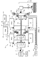
- Fig. 1 is a schematic diagram of an exemplary hybrid powertrain, in accordance with the present disclosure
- Fig. 2 is a schematic diagram of an exemplary architecture for a control system and hybrid powertrain, in accordance with the present disclosure.
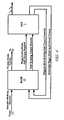
- Figs. 3 , 4 , 5 and 6 are schematic signal flow diagrams of a control scheme, in accordance with the present disclosure.
- Figs. 1 and 2 depict an exemplary electro-mechanical hybrid powertrain.
- the exemplary electro-mechanical hybrid powertrain in accordance with the present disclosure is depicted in Fig. 1 , comprising a two-mode, compound-split, electro-mechanical hybrid transmission 10 operatively connected to an engine 14 and torque machines comprising first and second electric machines ('MG-A') 56 and ('MG-B') 72.
- the engine 14 and first and second electric machines 56 and 72 each generate mechanical power which can be transferred to the transmission 10.
- the engine 14, transmission 10 and the torque machines comprising the first and second electric machines in this embodiment comprise torque actuators.
- the power generated by the engine 14 and the first and second electric machines 56 and 72 and transferred to the transmission 10 is described in terms of input and motor torques, referred to herein as T I , T A , and T B respectively, and speed, referred to herein as N I , N A , and N B , respectively.
- the exemplary engine 14 comprises a multi-cylinder internal combustion engine selectively operative in several states to transfer torque to the transmission 10 via an input member 12, and can be either a spark-ignition or a compression-ignition engine.
- the engine 14 includes a crankshaft (not shown) operatively coupled to the input member 12 of the transmission 10.
- a rotational speed sensor 11 monitors rotational speed of the input member 12.
- Power output from the engine 14, comprising rotational speed and engine torque can differ from the input speed N I and the input torque T I to the transmission 10 due to placement of torque-consuming components on the input member 12 between the engine 14 and the transmission 10, e.g., a hydraulic pump (not shown) and/or a torque management device (not shown).
- the exemplary transmission 10 comprises three planetary-gear sets 24, 26 and 28, and four selectively engageable torque-transferring devices, i.e., clutches C1 70, C2 62, C3 73, and C4 75.
- clutches refer to any type of friction torque transfer device including single or compound plate clutches or packs, band clutches, and brakes, for example.
- a hydraulic control circuit ('HYD') 42 preferably controlled by a transmission control module (hereafter 'TCM') 17, is operative to control clutch states.
- Clutches C2 62 and C4 75 preferably comprise hydraulically-applied rotating friction clutches.
- Clutches C 1 70 and C3 73 preferably comprise hydraulically-controlled stationary devices that can be selectively grounded to a transmission case 68.
- Each of the clutches C 1 70, C2 62, C3 73, and C4 75 is preferably hydraulically applied, selectively receiving pressurized hydraulic fluid via the hydraulic control circuit 42.
- the first and second electric machines 56 and 72 preferably comprise three-phase AC machines, each including a stator (not shown) and a rotor (not shown), and respective resolvers 80 and 82.
- the motor stator for each machine is grounded to an outer portion of the transmission case 68, and includes a stator core with coiled electrical windings extending therefrom.
- the rotor for the first electric machine 56 is supported on a hub plate gear that is operatively attached to shaft 60 via the second planetary gear set 26.
- the rotor for the second electric machine 72 is fixedly attached to a sleeve shaft hub 66.
- Each of the resolvers 80 and 82 preferably comprises a variable reluctance device including a resolver stator (not shown) and a resolver rotor (not shown).
- the resolvers 80 and 82 are appropriately positioned and assembled on respective ones of the first and second electric machines 56 and 72.
- Stators of respective ones of the resolvers 80 and 82 are operatively connected to one of the stators for the first and second electric machines 56 and 72.
- the resolver rotors are operatively connected to the rotor for the corresponding first and second electric machines 56 and 72.
- Each of the resolvers 80 and 82 is signally and operatively connected to a transmission power inverter control module (hereafter 'TPIM') 19, and each senses and monitors rotational position of the resolver rotor relative to the resolver stator, thus monitoring rotational position of respective ones of first and second electric machines 56 and 72. Additionally, the signals output from the resolvers 80 and 82 are interpreted to provide the rotational speeds for first and second electric machines 56 and 72, i.e., N A and N B , respectively.
- the transmission 10 includes an output member 64, e.g. a shaft, which is operably connected to a driveline 90 for a vehicle (not shown), to provide output power to the driveline 90 that is transferred to vehicle wheels 93, one of which is shown in Fig. 1 .
- the output power at the output member 64 is characterized in terms of an output rotational speed No and an output torque To.
- a transmission output speed sensor 84 monitors rotational speed and rotational direction of the output member 64.
- Each of the vehicle wheels 93 is preferably equipped with a sensor (not shown) adapted to monitor wheel speed, the output of which is monitored by a control module of a distributed control module system described with respect to Fig. 2 , to determine vehicle speed, and absolute and relative wheel speeds for braking control, traction control, and vehicle acceleration management.
- the input torque from the engine 14 and the motor torques from the first and second electric machines 56 and 72 (T I , T A , and T B respectively) are generated as a result of energy conversion from fuel or electrical potential stored in an electrical energy storage device (hereafter 'ESD') 74.
- the ESD 74 is high voltage DC-coupled to the TPIM 19 via DC transfer conductors 27.
- the transfer conductors 27 include a contactor switch 38. When the contactor switch 38 is closed, under normal operation, electric current can flow between the ESD 74 and the TPIM 19. When the contactor switch 38 is opened electric current flow between the ESD 74 and the TPIM 19 is interrupted.
- the TPIM 19 transmits electrical power to and from the first electric machine 56 through a first motor control module ('MCP-A') 33 using transfer conductors 29, and the TPIM 19 similarly transmits electrical power to and from the second electric machine 72 through a second motor control module ('MCP-B') 34 using transfer conductors 31 to meet the torque commands for the first and second electric machines 56 and 72 in response to the motor torques T A and T B .
- Electrical current is transmitted to and from the ESD 74 in accordance with whether the ESD 74 is being charged or discharged.
- the TPIM 19 preferably includes a hybrid control module (hereafter 'HCP') 5 and the pair of power inverters and respective motor control modules 33 and 34 configured to receive the torque commands and control inverter states therefrom for providing motor drive or regeneration functionality to meet the commanded motor torques T A and T B .
- the power inverters comprise known complementary three-phase power electronics devices, and each includes a plurality of insulated gate bipolar transistors (not shown) for converting DC power from the ESD 74 to AC power for powering respective ones of the first and second electric machines 56 and 72, by switching at high frequencies.
- the insulated gate bipolar transistors form a switch mode power supply configured to receive control commands.
- the three-phase inverters receive or supply DC electric power via DC transfer conductors 27 and transform it to or from three-phase AC power, which is conducted to or from the first and second electric machines 56 and 72 for operation as motors or generators via transfer conductors 29 and 31 respectively.
- Figs. 2 and 3 are schematic block diagrams of the distributed control module system of the control system.
- the term 'control system' is defined as the control modules, wiring harnesses (not shown), communications links, sensors and actuators that monitor and control operation of the powertrain system.
- the control system monitors sensor inputs and commands outputs for controlling the actuators.
- the distributed control module system comprises a subset of overall vehicle control architecture, and provides coordinated system control of the exemplary hybrid powertrain described in Fig. 1 .
- the control system includes the distributed control module system for synthesizing information and inputs, and executing algorithms to control actuators to meet control objectives, including objectives related to fuel economy, emissions, performance, drivability, and protection of hardware, including batteries of ESD 74 and the first and second electric machines 56 and 72.
- the distributed control module system includes an engine control module (hereafter 'ECM') 23, the TCM 17, a battery pack control module (hereafter 'BPCM') 21, a brake control module (hereafter 'BrCM') 22, and the TPIM 19.
- the HCP 5 provides supervisory control and coordination of the ECM 23, the TCM 17, the BPCM 21, the BrCM 22 and the TPIM 19.
- a user interface ('UI') 13 is preferably signally connected to a plurality of devices through which a vehicle operator controls, directs, and commands operation of the electro-mechanical hybrid powertrain.
- the devices include an accelerator pedal 113 ('AP'), an operator brake pedal 112 ('BP'), a transmission range selector 114 ('PRNDL'), and a vehicle speed cruise control (not shown).
- the transmission range selector 114 may have a discrete number of operator-selectable positions, including the rotational direction of the output member 64 to enable one of a forward and a reverse direction.
- the user interface 13 can comprise a single device, as shown, or alternatively can comprise a plurality of user interface devices directly connected to the individual control modules (not shown).
- the aforementioned control modules communicate with other control modules, sensors, and actuators via a communications link comprising a local area network (hereafter 'LAN') bus 6, in this embodiment.
- the LAN bus 6 allows for structured communication between the various control modules.
- the specific communication protocol utilized is application-specific.
- the LAN bus 6 and appropriate protocols provide for robust messaging and multi-control module interfacing between the aforementioned control modules, and other control modules providing functionality including e.g., antilock braking, traction control, and vehicle stability.
- Multiple communications buses may be used to improve communications speed and provide some level of signal redundancy and integrity.
- Communications between the MCP-A 33 and the HCP 5 and between the MCP-B 34 and the HCP 5 is preferably effected using direct links preferably comprising serial peripheral interface (hereafter 'SPI') buses 37.
- Communication between individual control modules can also be effected using a wireless link, e.g., a short range wireless radio communications bus (not shown).
- the HCP 5 provides supervisory control of the hybrid powertrain, serving to coordinate operation of the ECM 23, TCM 17, MCP-A 33, MCP-B 34, BrCM 22 and BPCM 21. Based upon various command signals from the user interface 13 and the hybrid powertrain, including the ESD 74, the HCP 5 determines an operator torque request, an output torque command, an engine input torque command, clutch torque(s) for the applied torque-transfer clutches C1 70, C2 62, C3 73, C4 75 of the transmission 10, and the motor torques T A and T B for the first and second electric machines 56 and 72. The HCP 5 sends commands to specific control modules to effect control of the engine 14, transmission 10 and the first and second electric machines 56 and 72.
- the ECM 23 is operatively connected to the engine 14, and functions to acquire data from sensors and control actuators of the engine 14 over a plurality of discrete lines, shown for simplicity as an aggregate bi-directional interface cable 35.
- the ECM 23 receives the engine input torque command from the HCP 5.
- the ECM 23 determines the actual engine input torque, T I , provided to the transmission 10 at that point in time based upon monitored engine speed and load, which is communicated to the HCP 5.
- the ECM 23 monitors input from the rotational speed sensor 11 to determine the engine input speed to the input member 12, which translates to the transmission input speed, N I .
- the ECM 23 monitors inputs from sensors (not shown) to determine states of other engine operating parameters including, e.g., a manifold pressure, engine coolant temperature, ambient air temperature, and ambient pressure.
- the engine load can be determined, for example, from the manifold pressure, or alternatively, from monitoring operator input to the accelerator pedal 113.
- the ECM 23 generates and communicates control signals to control engine actuators, including, e.g., fuel injectors, ignition modules, and throttle control modules, none of which are shown.
- the TCM 17 is operatively connected to the transmission 10 and monitors inputs from sensors (not shown) to determine states of transmission operating parameters.
- the TCM 17 generates and communicates control signals to control the transmission 10, including controlling the hydraulic circuit 42.
- Inputs from the TCM 17 to the HCP 5 include estimated clutch torques for each of the clutches, i.e., C 1 70, C2 62, C3 73, and C4 75, and rotational output speed, No, of the output member 64.
- Other actuators and sensors may be used to provide additional information from the TCM 17 to the HCP 5 for control purposes.
- the TCM 17 monitors inputs from pressure switches (not shown) and selectively actuates pressure control solenoids (not shown) and shift solenoids (not shown) of the hydraulic circuit 42 to selectively actuate the various clutches C1 70, C2 62, C3 73, and C4 75 to achieve various transmission operating range states, as described hereinbelow.
- the BPCM 21 is signally connected to sensors (not shown) to monitor the ESD 74, including states of electrical current and voltage parameters, to provide information indicative of parametric states of the batteries of the ESD 74 to the HCP 5.
- the parametric states of the batteries preferably include battery state-of-charge, battery voltage, battery temperature, and available battery power, referred to as a range P BAT_MIN to P BAT_MAX .
- the BrCM 22 is operatively connected to the friction brakes 94 on each of the vehicle wheels 93.
- Braking preferably comprises a blending of friction braking and regenerative braking.
- the BrCM 22 monitors the operator input to the brake pedal 112 and determines a net operator input to the brake pedal 112 and the accelerator pedal 113.
- the BrCM 22 commands friction braking by applying the friction brakes 94 and commands operation of the powertrain system through the HCP 5 to create a negative output torque to react with the driveline 90.
- the electro-mechanical transmission 10 and the engine 14 can generate a negative output torque that reacts with the driveline 90.
- the negative output torque reacted through the electro-mechanical transmission 10 can be transferred to the first and second electric machines 56 and 72 to generate electric power for storage in the ESD 74.
- the regenerative braking is effected through the driveline 90 by selectively applying one of the clutches and controlling the first and second electric machines 56 and 72 to react torque transferred from the driveline 90 through the power inverters and respective motor control modules to meet the commanded motor torques T A and T B which are determined based upon the negative output torque.
- the applied braking force and the negative output torque can decelerate and stop the vehicle so long as they are sufficient to overcome vehicle kinetic power at the wheel(s) 93.
- Each of the control modules ECM 23, TCM 17, HCP 5, MCP-A 33, MCP-B 34, BPCM 21, and BrCM 22 is preferably a general-purpose digital computer comprising a microprocessor or central processing unit, storage mediums comprising read only memory ('ROM'), random access memory ('RAM'), electrically programmable read only memory ('EPROM'), a high speed clock, analog to digital ('A/D') and digital to analog ('D/A') circuitry, and input/output circuitry and devices ('I/O') and appropriate signal conditioning and buffer circuitry.
- Each of the control modules has a set of control algorithms, comprising resident program instructions and calibrations stored in one of the storage mediums and executed to provide the respective functions of each computer.
- control algorithms are executed during preset loop cycles such that each algorithm is executed at least once each loop cycle.
- Algorithms stored in the non-volatile memory devices are executed by one of the central processing units to monitor inputs from the sensing devices and execute control and diagnostic routines to control operation of the actuators, using preset calibrations.
- Loop cycles are executed at regular intervals, for example each 3.125, 6.25, 12.5, 25 and 100 milliseconds during ongoing operation of the hybrid powertrain.
- algorithms may be executed in response to the occurrence of an event.
- the exemplary hybrid powertrain selectively operates in one of several states that can be described in terms of engine states comprising one of an engine-on state ('ON') and an engine-off state ('OFF'), and transmission operating range states comprising a plurality of fixed gears and continuously variable operating modes, described with reference to Table 1, below.
- Each of the transmission operating range states is described in the table and indicates which of the specific clutches C1 70, C2 62, C3 73, and C4 75 are applied for each of the operating range states.
- a first continuously variable mode i.e., EVT Mode 1, or M1 is selected by applying clutch C1 70 only in order to "ground” the outer gear member of the third planetary gear set 28.
- the engine state can be one of ON ('M1_Eng_On') or OFF ('M1_Eng-Off').
- a second continuously variable mode i.e., EVT Mode 2, or M2, is selected by applying clutch C2 62 only to connect the shaft 60 to the carrier of the third planetary gear set 28.
- the engine state can be one of ON ('M2_Eng_On') or OFF ('M2_Eng_Off').
- 'RPM' revolutions per minute
- a fixed gear operation provides a fixed ratio operation of input-to-output speed of the transmission 10, i.e., N I /N O .
- a first fixed gear operation ('G1') is selected by applying clutches C 1 70 and C4 75.
- a second fixed gear operation ('G2') is selected by applying clutches C1 70 and C2 62.
- a third fixed gear operation ('G3') is selected by applying clutches C2 62 and C4 75.
- a fourth fixed gear operation ('G4') is selected by applying clutches C2 62 and C3 73.
- the fixed ratio operation of input-to-output speed increases with increased fixed gear operation due to decreased gear ratios in the planetary gears 24, 26, and 28.
- the rotational speeds of the first and second electric machines 56 and 72, N A and N B respectively, are dependent on internal rotation of the mechanism as defined by the clutching and are proportional to the input speed measured at the input shaft 12.
- the HCP 5 and one or more of the other control modules determine torque commands to control torque actuators to meet the operator torque request at the output member 64 for transference to the driveline 90.
- the torque actuators preferably include a plurality of torque generative devices, e.g., the engine 14 and the first and second electric machines 56 and 72 and a torque transferring device comprising the transmission 10 in this embodiment.
- the HCP 5 determines the operator torque request and an output torque command from the transmission 10 to the driveline 90 and actuator controls including an input torque from the engine 14, clutch torques for the torque-transfer clutches C1 70, C2 62, C3 73, C4 75 of the transmission 10 and the motor torque commands for the first and second electric machines 56 and 72 based upon operator commands from the user interface 13.
- Torque security of the hybrid powertrain system can be achieved by executing integrity tests of the control system which include monitoring hardware integrity, monitoring integrity of algorithms and memory devices, securing and monitoring integrity of critical signals during communications within one of the control modules and communications between the control modules, monitoring processor integrity and executing remedial actions.
- Torque security in presence of an observed fault can include limiting a torque actuator command signal. This can include maximum and minimum limits on torque actuator command signals and maximum rates of change on torque actuator command signals.
- motor torque commands T A and T B can be limited to maximum and minimum motor torques, and changes in the motor torque commands T A and T B can be limited to effect a maximum rate of change in the output torque, e.g., 0.2g.
- Critical signals are secured and monitored to achieve signal integrity by individually securing and monitoring the control modules and securing and monitoring the serial communications links between the control modules.
- Critical signals include: input signals from sensors affecting torque output. Signal integrity of a critical signal can be secured and monitored by redundantly storing the critical signal in dual memory locations within the originating control module, referred to as 'dual store'. Signal integrity can be secured and monitored by redundantly calculating critical signals comprising control parameters, e.g., motor torque commands T A and T B , and rationalizing the primary value with the redundant value. Signal integrity can be secured and monitored by back-calculating a critical control command value and verifying that it matches the original request. Signal integrity can be secured and monitored by rationalizing an achieved input torque and motor torque value against the commanded input torque and motor torque value.
- Monitoring integrity of a signal transmitted over a serial bus includes detecting missing data, e.g., detecting loss of a message frame and taking a short term mitigation action and informing the receiving control module that no new data is available. Detecting missing data also includes detecting long term loss of communications to one of the control modules and taking a remedial action.
- the distributed control module system of the exemplary embodiment preferably includes each of the torque actuators controlled by a separate control module.
- This embodiment includes the ECM 23 that monitors sensors and control actuators of the engine 14, the TCM 17 that monitors sensors and control actuators of the transmission 10, the MCP-A 33 that monitors sensors and control actuators of the first electric machine 56, and the MCP-B 34 that monitors sensors and control actuators of the second electric machine 72.
- the HCP 5 monitors inputs from and commands operation of the ECM 23, TCM 17, MCP-A 33 and MCP-B 34.
- Each of the ECM 23, MCP-A 33, MCP-B 34 and TCM 17 is responsible for closed loop monitoring and self-security based on secured commands received from the HCP 5.
- Fig. 4 shows a control system architecture for managing signal flow in the distributed control system to effect tractive braking through one or more of the vehicle wheels 93, an embodiment of which is described with reference to the hybrid powertrain described hereinabove.
- the operator braking request that is input to the brake pedal 112 ('Operator Braking Request') is preferably directly monitored by the BrCM 22 from which it determines a total braking torque request ('Total Braking Torque Request').
- the BrCM 22 generates a regenerative braking axle torque request ('Regenerative Brake Axle Torque Request') based upon the total braking torque request and inputs from the HCP 5 comprising a regenerative braking axle torque capacity ('Regenerative Braking Axle Torque Capacity') and any presently applied regenerative braking torque ('Estimated Regen Braking Achieved Torque').
- a regenerative braking axle torque request based upon the total braking torque request and inputs from the HCP 5 comprising a regenerative braking axle torque capacity ('Regenerative Braking Axle Torque Capacity') and any presently applied regenerative braking torque ('Estimated Regen Braking Achieved Torque').
- the BrCM 22 generates a control signal ('Friction Brake Control') comprising a command for friction braking torque to control the friction brake(s) 94 in each of the wheels 93 based upon a difference between the operator braking request and the regenerative braking torque that can be reacted through the transmission 14 by operation of the first and second electric machines 56 and 72 as estimated by the HCP 5.
- the BrCM 22 acts as a master arbitrator for controlling the friction brake(s) 94 and the transmission 10 to meet the operator braking request.
- the HCP 5 determines the regenerative braking axle torque capacity, which is a torque-based measurement of the ability of the transmission 10 to react torque from the driveline 90 through the selectively applied clutches C 1 70, C2 62, C3 73, and C4 75 to the first and second electric machines 56 and 72, limited by the maximum brake output torque.
- the immediate output torque request is determined based upon operator inputs to the accelerator pedal 113 and the brake pedal 112.
- the present output torque can be determined based on achieved motor torques, actual engine torque, output speed and output speed derivative from the transmission 10, engine input speed and transmission operating range state.
- the achieved motor torques are preferably based upon electric charging current flow between the first and second electric machines 56 and 72 and the ESD 74 for this embodiment.
- the HCP 5 estimates the presently applied regenerative braking torque reacted from the driveline 90 and the output member 64 of the transmission 10 based upon a difference between the present output torque and an immediate output torque request.
- the HCP 5 redundantly calculates the presently applied regenerative braking torque.
- the redundantly calculated presently applied regenerative braking torque is compared to the primary presently applied regenerative braking torque in a rationality check, and when the absolute values of the signals match within a calibratable tolerance, the system is presumed to be working correctly.
- the primary presently applied regenerative braking torque signal is dual stored for communication. A preferred method for executing a rationality check is described hereinbelow with reference to Fig. 5 .
- the primary presently applied regenerative braking torque and the regenerative braking axle torque capacity are communicated over the LAN 6 to the BrCM 22.
- a preferred method for communicating a critical signal over the LAN 6 is described hereinbelow with reference to Fig. 6 .
- the HCP 5 determines the preferred output torque from the powertrain and generates the motor torque commands ('T A ', 'T B ') for controlling the first and second electric machines 56 and 72 based upon the regenerative braking axle torque request.
- the timing sequence of transmitting signals from the brake pedal 112 to the BrCM 22 and subsequently to the HCP 5 is intentional, as the most currently available operator input to the brake pedal 112 can be used to control vehicle braking during a braking event.
- the HCP 5 leverages recuperation of kinetic energy through the regenerative braking to generate storable electric power and improve operating efficiency.
- the regenerative braking axle torque request, the regenerative braking axle torque capacity, and the presently applied regenerative braking torque comprise critical signals that are preferably communicated between the HCP 5 and the BrCM 22 using the LAN 6.
- the HCP 5 acts to inhibit regenerative braking by overwriting the communicated regenerative braking axle torque request and ramping it to a zero torque output.
- the HCP 5 ramps the regenerative braking axle torque capacity to a zero torque output and continues to report the presently applied regenerative braking torque, both which are communicated to the BrCM 22.
- the BrCM 22 is thus informed that there is no current capacity in the powertrain for regenerative braking, and the BrCM 22 controls the friction brake(s) 94 accordingly.
- the BrCM 22 ramps the regenerative braking axle torque request to zero, in response to the ramping of the regenerative braking axle torque capacity to zero torque output.
- the HCP 5 continues to communicate the presently applied regenerative braking torque to the BrCM 22.
- the BrCM 22 preferably ramps the regenerative braking axle torque request to zero at a calibrated ramp rate based upon the presently applied regenerative braking torque to minimize driveline torque disturbance.
- the control system continues to operate the powertrain and inhibits the regenerative braking function.
- the BrCM 22 controls the friction brake(s) 94 to achieve braking torque in response to the operator braking request.
- System operation is continually monitored.
- a detected fault can be cleared, e.g., by determining the source of the fault is no longer present.
- the regenerative braking function can be resumed. This includes the BrCM 22 preferably ramping in the regenerative braking axle torque request at a predetermined rate based upon the operator braking request.
- the regenerative braking axle torque capacity is immediately returned to the determined value for regenerative braking axle torque capacity.
- the presently applied regenerative braking torque can be recalculated, as previously described and communicated.
- Fig. 5 shows signal flow to secure and verify integrity of an input signal in a control module.
- the signal input in this embodiment can comprise one of the operator braking request, the regenerative braking axle torque request, the regenerative braking axle torque capacity, and the presently applied regenerative braking torque, each which is described with reference to Fig. 4 .
- the input signal is generated (502) and is captured as a primary signal 504 and a redundant signal 504'. This can include the input signal from the sensor converted to a digital representation of the input from the sensor using an analog-to-digital converter (not shown) which may be interposed between the sensor and the originating control module. Diagnostics ('Diagnostics') are executed on both the primary signal and the redundant signal (506, 506').
- Diagnostics can include limit checks that indicate when the signal is outside of a predetermined operating range for the signal, a rationality check of the signal, and other diagnostics check that can indicate corruption of the signal. If a corrupted signal is detected ('Signal Fault') in either or both the primary signal and the redundant signal, a default signal is generated ('Defaulting') (508, 508') and communicated to a rationality check 510.
- the default signal preferably comprises a predetermined signal that is recognizable in the control module as indicating the primary signal or the redundant signal has been corrupted. When a fault is not detected ('No Fault'), the primary and/or the redundant signals are communicated to the rationality check 510.
- the rationality check 510 compares the primary signal and the redundant signal and identifies a fault ('Fault') when there is a difference detected between the primary and redundant signals.
- the rationality check 510 indicates that the primary signal is valid ('Valid Signal')
- the primary signal is communicated to a dual store function ('Dual Store') 511.
- the dual store function 511 monitors and compares present contents in first and second memory locations 512, 512' to verify integrity of the memory locations, preferably during each 6.25 ms loop cycle.
- the primary signal is stored as the primary signal in the first memory location ('Store Primary Signal') (512) and stored as a secondary signal in the second memory location ('Store Secondary Signal') (512').
- the primary signal stored in the first memory location is subsequently communicated to a control path ('Primary Signal To Control Path').
- the secondary signal stored in the second memory location is subsequently communicated to a security path. ('Secondary Signal To Security Path'). If there is a difference between the present contents of the memory locations, a fault ('Fault') is recorded indicating corruption of one of the first and second memory locations.
- the control system identifies occurrence of the fault ('Fault').
- the control system determines whether the corrupted signal has matured ('Mature Fault') (514), and executes remedial action (516) to mitigate risks associated with the presence of the fault.
- a fault maturation algorithm can be executed, including, e.g., an X of Y routine wherein a fault has matured when X mismatched signals are observed out of immediately preceding Y signal observations.
- An example includes determining a fault has matured when more than half the immediately preceding observations indicate a corrupted signal.
- Monitoring integrity of a signal transmitted over a serial bus includes detecting missing data, e.g., detecting loss of a message frame and taking a short term mitigation action and informing the receiving control module that no new data is available. Detecting missing data also includes detecting long term loss of communications to one of the control modules and taking a remedial action.
- Fig. 6 shows communicating the redundantly stored signals, e.g., the dual stored signal from Fig. 5 , from the originating control module to the receiving control module using a communications bus, e.g., LAN bus 6 or SPI bus 37.
- the originating control module generates a message ('Tx Message') 610 to transmit.
- the transmitted message 610 includes words comprising other signals ('TSig_1' and 'TSig_2', 'TSig_4', 'TSig_5' and 'TSig_6').
- the primary signal being secured is preferably inserted as a third word ('TSig 3').
- the subsequent word comprises an alive rolling count ('Build ARC') consisting of a two bit digital word (one of 00, 01, 10, 11) wherein the two bit word sequentially increments from 00 to 01 to 10 to 11 and repetitively cycles back to begin at 00 for consecutively generated and transmitted messages.
- the control module generates a fifth word ('TSig_3_PV') which preferably includes adding the alive rolling count to the primary signal and generating a protection value ('Build PV').
- Generating the protection value preferably comprises generating a logic complement, e.g., a 2's complement, of the primary signal with the added alive rolling count.
- the message 610 is transmitted over one of the serial communications links 6, 37 and received at the receiving control module as a received message ('Rx Message') 610'.
- the received message 610' is decoded, including determining received words ('RSig_1', 'RSig_2', 'RSig_3', 'RSig_3_ARC', 'RSig_3_PV', 'RSig_4', 'RSig_5' and 'RSig_6').
- the third word ('RSig_3') is captured and will be stored in a predetermined memory location as a received primary signal ('R/Primary Signal') subsequent to a successful rationality check 515 and a successful dual-store function 517 of memory locations 519 and 519'.
- the fourth word ('RSig_3_ARC') is captured and interpreted as a received alive rolling count.
- the received alive rolling count is compared to an expected alive rolling count, i.e., the next two bit word in the sequence from 00 to 01 to 10 to 11 ('ARC Fault') (518). A fault is recorded if the received alive rolling count is not equal to an expected alive rolling count (518).
- the fifth word ('RSig_3_PV') is captured and a received secondary signal ('R/Secondary Signal') is determined by generating a corresponding inverse logic complement of the fifth word and parsing out the alive rolling count ('Parse PV/Check PV'). Preferably the alive rolling count from the fourth word is subtracted therefrom.
- the rationality check 515 compares the received primary signal and the received secondary signal and identifies a fault ('Fault') when a difference is detected, preferably prior to storing the received primary signal.
- the primary signal is communicated to the dual store function ('Dual Store') 517.
- the dual store function 517 monitors and compares present contents in first memory location 519 and second memory location 519' to verify integrity of the memory locations, preferably during each 6.25 ms loop cycle.
- the received primary signal is dual-stored, i.e., the received primary signal ('R/Primary Signal') is stored in both the first and second memory locations 519 and 519'. If there is a difference between the present contents of the first and second memory locations 519 and 519', a fault ('Fault') is recorded indicating corruption of one of the first and second memory locations 519 and 519' and remedial action is undertaken consistent with the specific signal.
- the control system identifies occurrence of the fault ('Fault').
- the control system determines whether the corrupted signal has matured to a fault using a fault maturation algorithm ('Mature Fault') (521), and executes remedial action (523) to mitigate risks associated with the presence of the fault.
- the fault maturation algorithm can be executed to determine whether the corrupted signal has matured, including, e.g., an X of Y routine wherein a fault has matured when X mismatched signals are observed out of immediately preceding Y signal observations.
- An example includes determining a fault has matured when more than half the immediately preceding observations indicate a corrupted signal.
- Messages are transmitted at a rate dependent upon the communications rate of the specific bus, e.g., the LAN bus 6 or SPI bus 37, which can be 1 Mbps.
- messages are communicated across the LAN bus 6 every 6.25 ms loop cycle. Messages can be sent serially and evaluated.
- the aforementioned signal monitoring software can execute a detection algorithm in one of the loop cycles to detect signal inconsistency between the primary signal and the secondary signal. When an inconsistency is detected, it is recorded as a mismatch count in a fault maturation algorithm, e.g., an X of Y routine wherein a fault is detected when X mismatched signals are observed out of immediately preceding Y signal observations.
- the control system can execute remedial action to mitigate risks associated with the presence of a fault identified by the fault maturation algorithm.
- Detection of a fault in communications can include detecting temporary loss of data and missing data, detecting corrupted data, and no data. Detecting missing data includes detecting loss of a message frame and taking a short term mitigation action and informing the receiving control module that no new data is available. Detecting no data includes detecting a long term loss of communications to one of the control modules and taking a remedial action.
- the control module can enter a fail-soft mode, wherein torque commands are initially held unchanged, i.e., at steady-state torque levels for a predetermined period of time and then ramped down toward zero torque command.
- control modules continue to communicate, and when valid communications are reestablished, torque commands can be ramped up to achieve the operator torque request, with rate-change of the output torque controlled to effect the previously described maximum rate of change in output torque, e.g., 0.2g.
- rate-change of the output torque controlled to effect the previously described maximum rate of change in output torque, e.g., 0.2g.
- powertrain operation can be transitioned to a degraded state that limits output torque to a predetermined maximum level, preferably permitting some level of operation for a remainder of the key cycle.
- the remedial action and fault mitigation can include disabling the actuator controlled by the respective control module in which the fault occurred.
- the remedial action can be actuator-specific or system-wide, and places the powertrain in a torque-safe state.
- the remedial action further includes storing an OBD compliant code for subsequent retrieval.
- a diagnostic may preliminarily identify a fault pending, meaning data corruption or an inconsistency has been detected but the fault maturation algorithm has not reached its threshold.
- the hardware integrity can be further determined using diagnostics software that monitors the sensors and actuators of the control system.
Landscapes
- Engineering & Computer Science (AREA)
- Transportation (AREA)
- Mechanical Engineering (AREA)
- Chemical & Material Sciences (AREA)
- Combustion & Propulsion (AREA)
- Automation & Control Theory (AREA)
- Human Computer Interaction (AREA)
- Electric Propulsion And Braking For Vehicles (AREA)
- Hybrid Electric Vehicles (AREA)
Abstract
Description
- This application claims the benefit of
U.S. Provisional Application No. 60/983,246, filed on 10/29/2007 - This disclosure is related to control systems for hybrid powertrain systems.
- The statements in this section merely provide background information related to the present disclosure and may not constitute prior art.
- Known hybrid powertrain architectures can include multiple torque-generative devices, including internal combustion engines and non-combustion machines, e.g., electric machines, which transmit torque through a transmission device to an output member. One exemplary hybrid powertrain includes a two-mode, compound-split, electro-mechanical transmission which utilizes an input member for receiving tractive torque from a prime mover power source, preferably an internal combustion engine, and an output member. The output member can be operatively connected to a driveline for a motor vehicle for transmitting tractive torque thereto. Machines, operative as motors or generators, can generate torque inputs to the transmission independently of a torque input from the internal combustion engine. The machines may transform vehicle kinetic energy transmitted through the vehicle driveline to energy that is storable in an energy storage device. A control system monitors various inputs from the vehicle and the operator and provides operational control of the hybrid powertrain, including controlling transmission operating state and gear shifting, controlling the torque-generative devices, and regulating the power interchange among the energy storage device and the machines to manage outputs of the transmission, including torque and rotational speed.
- A powertrain system includes an engine and a torque actuator coupled to an output member, the output member coupled to a driveline to transfer tractive power to a wheel including a friction brake, the torque actuator operative to react tractive power transferred from the wheel. A method for controlling the powertrain system includes monitoring an operator braking request and determining a request for regenerative braking torque. The request for regenerative braking torque is monitored, and the the torque actuator is commanded to react tractive power based upon the monitored request for regenerative braking torque. Achieved regenerative braking torque is monitored, and operation of the torque actuator is inhibited when a fault is detected in one of the monitored request for regenerative braking torque and the monitored achieved regenerative braking torque
- One or more embodiments will now be described, by way of example, with reference to the accompanying drawings, in which:
-
Fig. 1 is a schematic diagram of an exemplary hybrid powertrain, in accordance with the present disclosure; -
Fig. 2 is a schematic diagram of an exemplary architecture for a control system and hybrid powertrain, in accordance with the present disclosure; and -
Figs. 3 ,4 ,5 and6 are schematic signal flow diagrams of a control scheme, in accordance with the present disclosure. - Referring now to the drawings, wherein the showings are for the purpose of illustrating certain exemplary embodiments only and not for the purpose of limiting the same,
Figs. 1 and2 depict an exemplary electro-mechanical hybrid powertrain. The exemplary electro-mechanical hybrid powertrain in accordance with the present disclosure is depicted inFig. 1 , comprising a two-mode, compound-split, electro-mechanical hybrid transmission 10 operatively connected to anengine 14 and torque machines comprising first and second electric machines ('MG-A') 56 and ('MG-B') 72. Theengine 14 and first and secondelectric machines transmission 10. Theengine 14,transmission 10 and the torque machines comprising the first and second electric machines in this embodiment comprise torque actuators. The power generated by theengine 14 and the first and secondelectric machines transmission 10 is described in terms of input and motor torques, referred to herein as TI, TA, and TB respectively, and speed, referred to herein as NI, NA, and NB, respectively. - The
exemplary engine 14 comprises a multi-cylinder internal combustion engine selectively operative in several states to transfer torque to thetransmission 10 via aninput member 12, and can be either a spark-ignition or a compression-ignition engine. Theengine 14 includes a crankshaft (not shown) operatively coupled to theinput member 12 of thetransmission 10. Arotational speed sensor 11 monitors rotational speed of theinput member 12. Power output from theengine 14, comprising rotational speed and engine torque, can differ from the input speed NI and the input torque TI to thetransmission 10 due to placement of torque-consuming components on theinput member 12 between theengine 14 and thetransmission 10, e.g., a hydraulic pump (not shown) and/or a torque management device (not shown). - The
exemplary transmission 10 comprises three planetary-gear sets clutches C1 70,C2 62,C3 73, andC4 75. As used herein, clutches refer to any type of friction torque transfer device including single or compound plate clutches or packs, band clutches, and brakes, for example. A hydraulic control circuit ('HYD') 42, preferably controlled by a transmission control module (hereafter 'TCM') 17, is operative to control clutch states.Clutches C2 62 andC4 75 preferably comprise hydraulically-applied rotating friction clutches. Clutches C 1 70 andC3 73 preferably comprise hydraulically-controlled stationary devices that can be selectively grounded to atransmission case 68. Each of the clutches C 1 70,C2 62,C3 73, andC4 75 is preferably hydraulically applied, selectively receiving pressurized hydraulic fluid via thehydraulic control circuit 42. - The first and second
electric machines respective resolvers transmission case 68, and includes a stator core with coiled electrical windings extending therefrom. The rotor for the firstelectric machine 56 is supported on a hub plate gear that is operatively attached toshaft 60 via the secondplanetary gear set 26. The rotor for the secondelectric machine 72 is fixedly attached to asleeve shaft hub 66. - Each of the
resolvers resolvers electric machines resolvers electric machines electric machines resolvers electric machines resolvers electric machines - The
transmission 10 includes anoutput member 64, e.g. a shaft, which is operably connected to adriveline 90 for a vehicle (not shown), to provide output power to thedriveline 90 that is transferred tovehicle wheels 93, one of which is shown inFig. 1 . The output power at theoutput member 64 is characterized in terms of an output rotational speed No and an output torque To. A transmissionoutput speed sensor 84 monitors rotational speed and rotational direction of theoutput member 64. Each of thevehicle wheels 93 is preferably equipped with a sensor (not shown) adapted to monitor wheel speed, the output of which is monitored by a control module of a distributed control module system described with respect toFig. 2 , to determine vehicle speed, and absolute and relative wheel speeds for braking control, traction control, and vehicle acceleration management. - The input torque from the
engine 14 and the motor torques from the first and secondelectric machines 56 and 72 (TI, TA, and TB respectively) are generated as a result of energy conversion from fuel or electrical potential stored in an electrical energy storage device (hereafter 'ESD') 74. The ESD 74 is high voltage DC-coupled to the TPIM 19 viaDC transfer conductors 27. Thetransfer conductors 27 include acontactor switch 38. When thecontactor switch 38 is closed, under normal operation, electric current can flow between theESD 74 and theTPIM 19. When thecontactor switch 38 is opened electric current flow between theESD 74 and the TPIM 19 is interrupted. The TPIM 19 transmits electrical power to and from the firstelectric machine 56 through a first motor control module ('MCP-A') 33 usingtransfer conductors 29, and theTPIM 19 similarly transmits electrical power to and from the secondelectric machine 72 through a second motor control module ('MCP-B') 34 usingtransfer conductors 31 to meet the torque commands for the first and secondelectric machines ESD 74 in accordance with whether the ESD 74 is being charged or discharged. - The TPIM 19 preferably includes a hybrid control module (hereafter 'HCP') 5 and the pair of power inverters and respective
motor control modules ESD 74 to AC power for powering respective ones of the first and secondelectric machines DC transfer conductors 27 and transform it to or from three-phase AC power, which is conducted to or from the first and secondelectric machines transfer conductors -
Figs. 2 and 3 are schematic block diagrams of the distributed control module system of the control system. As used herein, the term 'control system' is defined as the control modules, wiring harnesses (not shown), communications links, sensors and actuators that monitor and control operation of the powertrain system. The control system monitors sensor inputs and commands outputs for controlling the actuators. The distributed control module system comprises a subset of overall vehicle control architecture, and provides coordinated system control of the exemplary hybrid powertrain described inFig. 1 . The control system includes the distributed control module system for synthesizing information and inputs, and executing algorithms to control actuators to meet control objectives, including objectives related to fuel economy, emissions, performance, drivability, and protection of hardware, including batteries ofESD 74 and the first and secondelectric machines TCM 17, a battery pack control module (hereafter 'BPCM') 21, a brake control module (hereafter 'BrCM') 22, and theTPIM 19. TheHCP 5 provides supervisory control and coordination of theECM 23, theTCM 17, theBPCM 21, theBrCM 22 and theTPIM 19. A user interface ('UI') 13 is preferably signally connected to a plurality of devices through which a vehicle operator controls, directs, and commands operation of the electro-mechanical hybrid powertrain. The devices include an accelerator pedal 113 ('AP'), an operator brake pedal 112 ('BP'), a transmission range selector 114 ('PRNDL'), and a vehicle speed cruise control (not shown). Thetransmission range selector 114 may have a discrete number of operator-selectable positions, including the rotational direction of theoutput member 64 to enable one of a forward and a reverse direction. Theuser interface 13 can comprise a single device, as shown, or alternatively can comprise a plurality of user interface devices directly connected to the individual control modules (not shown). - The aforementioned control modules communicate with other control modules, sensors, and actuators via a communications link comprising a local area network (hereafter 'LAN')
bus 6, in this embodiment. TheLAN bus 6 allows for structured communication between the various control modules. The specific communication protocol utilized is application-specific. TheLAN bus 6 and appropriate protocols provide for robust messaging and multi-control module interfacing between the aforementioned control modules, and other control modules providing functionality including e.g., antilock braking, traction control, and vehicle stability. Multiple communications buses may be used to improve communications speed and provide some level of signal redundancy and integrity. Communications between the MCP-A 33 and theHCP 5 and between the MCP-B 34 and theHCP 5 is preferably effected using direct links preferably comprising serial peripheral interface (hereafter 'SPI')buses 37. Communication between individual control modules can also be effected using a wireless link, e.g., a short range wireless radio communications bus (not shown). - The
HCP 5 provides supervisory control of the hybrid powertrain, serving to coordinate operation of theECM 23,TCM 17, MCP-A 33, MCP-B 34,BrCM 22 andBPCM 21. Based upon various command signals from theuser interface 13 and the hybrid powertrain, including theESD 74, theHCP 5 determines an operator torque request, an output torque command, an engine input torque command, clutch torque(s) for the applied torque-transfer clutches C1 70,C2 62,C3 73,C4 75 of thetransmission 10, and the motor torques TA and TB for the first and secondelectric machines HCP 5 sends commands to specific control modules to effect control of theengine 14,transmission 10 and the first and secondelectric machines - The
ECM 23 is operatively connected to theengine 14, and functions to acquire data from sensors and control actuators of theengine 14 over a plurality of discrete lines, shown for simplicity as an aggregatebi-directional interface cable 35. TheECM 23 receives the engine input torque command from theHCP 5. TheECM 23 determines the actual engine input torque, TI, provided to thetransmission 10 at that point in time based upon monitored engine speed and load, which is communicated to theHCP 5. TheECM 23 monitors input from therotational speed sensor 11 to determine the engine input speed to theinput member 12, which translates to the transmission input speed, NI. TheECM 23 monitors inputs from sensors (not shown) to determine states of other engine operating parameters including, e.g., a manifold pressure, engine coolant temperature, ambient air temperature, and ambient pressure. The engine load can be determined, for example, from the manifold pressure, or alternatively, from monitoring operator input to theaccelerator pedal 113. TheECM 23 generates and communicates control signals to control engine actuators, including, e.g., fuel injectors, ignition modules, and throttle control modules, none of which are shown. - The
TCM 17 is operatively connected to thetransmission 10 and monitors inputs from sensors (not shown) to determine states of transmission operating parameters. TheTCM 17 generates and communicates control signals to control thetransmission 10, including controlling thehydraulic circuit 42. Inputs from theTCM 17 to theHCP 5 include estimated clutch torques for each of the clutches, i.e., C 1 70,C2 62,C3 73, andC4 75, and rotational output speed, No, of theoutput member 64. Other actuators and sensors may be used to provide additional information from theTCM 17 to theHCP 5 for control purposes. TheTCM 17 monitors inputs from pressure switches (not shown) and selectively actuates pressure control solenoids (not shown) and shift solenoids (not shown) of thehydraulic circuit 42 to selectively actuate thevarious clutches C1 70,C2 62,C3 73, andC4 75 to achieve various transmission operating range states, as described hereinbelow. - The
BPCM 21 is signally connected to sensors (not shown) to monitor theESD 74, including states of electrical current and voltage parameters, to provide information indicative of parametric states of the batteries of theESD 74 to theHCP 5. The parametric states of the batteries preferably include battery state-of-charge, battery voltage, battery temperature, and available battery power, referred to as a range PBAT_MIN to PBAT_MAX. - The
BrCM 22 is operatively connected to thefriction brakes 94 on each of thevehicle wheels 93. Braking preferably comprises a blending of friction braking and regenerative braking. TheBrCM 22 monitors the operator input to thebrake pedal 112 and determines a net operator input to thebrake pedal 112 and theaccelerator pedal 113. TheBrCM 22 commands friction braking by applying thefriction brakes 94 and commands operation of the powertrain system through theHCP 5 to create a negative output torque to react with thedriveline 90. The electro-mechanical transmission 10 and theengine 14 can generate a negative output torque that reacts with thedriveline 90. The negative output torque reacted through the electro-mechanical transmission 10 can be transferred to the first and secondelectric machines ESD 74. The regenerative braking is effected through thedriveline 90 by selectively applying one of the clutches and controlling the first and secondelectric machines driveline 90 through the power inverters and respective motor control modules to meet the commanded motor torques TA and TB which are determined based upon the negative output torque. The applied braking force and the negative output torque can decelerate and stop the vehicle so long as they are sufficient to overcome vehicle kinetic power at the wheel(s) 93. - Each of the
control modules ECM 23,TCM 17,HCP 5, MCP-A 33, MCP-B 34,BPCM 21, andBrCM 22 is preferably a general-purpose digital computer comprising a microprocessor or central processing unit, storage mediums comprising read only memory ('ROM'), random access memory ('RAM'), electrically programmable read only memory ('EPROM'), a high speed clock, analog to digital ('A/D') and digital to analog ('D/A') circuitry, and input/output circuitry and devices ('I/O') and appropriate signal conditioning and buffer circuitry. Each of the control modules has a set of control algorithms, comprising resident program instructions and calibrations stored in one of the storage mediums and executed to provide the respective functions of each computer. Information transfer between the control modules is preferably accomplished using theLAN bus 6 andSPI buses 37. The control algorithms are executed during preset loop cycles such that each algorithm is executed at least once each loop cycle. Algorithms stored in the non-volatile memory devices are executed by one of the central processing units to monitor inputs from the sensing devices and execute control and diagnostic routines to control operation of the actuators, using preset calibrations. Loop cycles are executed at regular intervals, for example each 3.125, 6.25, 12.5, 25 and 100 milliseconds during ongoing operation of the hybrid powertrain. Alternatively, algorithms may be executed in response to the occurrence of an event. - The exemplary hybrid powertrain selectively operates in one of several states that can be described in terms of engine states comprising one of an engine-on state ('ON') and an engine-off state ('OFF'), and transmission operating range states comprising a plurality of fixed gears and continuously variable operating modes, described with reference to Table 1, below.
Table 1 Description Engine Transmission Operating Applied Clutches State Range State M1_Eng_Off OFF EVT Mode 1 C1 70M1_Eng_On ON EVT Mode 1 C1 70G1 ON Fixed Gear Ratio 1 C1 70C4 75G2 ON Fixed Gear Ratio 2 C1 70C2 62M2_Eng_Off OFF EVT Mode 2 C2 62M2_Eng_On ON EVT Mode 2 C2 62G3 ON Fixed Gear Ratio 3 C2 62C4 75G4 ON Fixed Gear Ratio 4 C2 62C3 73 - Each of the transmission operating range states is described in the table and indicates which of the
specific clutches C1 70,C2 62,C3 73, andC4 75 are applied for each of the operating range states. A first continuously variable mode, i.e., EVT Mode 1, or M1, is selected by applyingclutch C1 70 only in order to "ground" the outer gear member of the third planetary gear set 28. The engine state can be one of ON ('M1_Eng_On') or OFF ('M1_Eng-Off'). A second continuously variable mode, i.e., EVT Mode 2, or M2, is selected by applyingclutch C2 62 only to connect theshaft 60 to the carrier of the third planetary gear set 28. The engine state can be one of ON ('M2_Eng_On') or OFF ('M2_Eng_Off'). For purposes of this description, when the engine state is OFF, the engine input speed is equal to zero revolutions per minute ('RPM'), i.e., the engine crankshaft is not rotating. A fixed gear operation provides a fixed ratio operation of input-to-output speed of thetransmission 10, i.e., NI/NO. A first fixed gear operation ('G1') is selected by applying clutches C 1 70 andC4 75. A second fixed gear operation ('G2') is selected by applyingclutches C1 70 andC2 62. A third fixed gear operation ('G3') is selected by applyingclutches C2 62 andC4 75. A fourth fixed gear operation ('G4') is selected by applyingclutches C2 62 andC3 73. The fixed ratio operation of input-to-output speed increases with increased fixed gear operation due to decreased gear ratios in theplanetary gears electric machines input shaft 12. - In response to operator input via the
accelerator pedal 113, thebrake pedal 112, and thetransmission range selector 114, as captured by theuser interface 13, theHCP 5 and one or more of the other control modules determine torque commands to control torque actuators to meet the operator torque request at theoutput member 64 for transference to thedriveline 90. The torque actuators preferably include a plurality of torque generative devices, e.g., theengine 14 and the first and secondelectric machines transmission 10 in this embodiment. Based upon operator commands from theuser interface 13, theHCP 5 determines the operator torque request and an output torque command from thetransmission 10 to thedriveline 90 and actuator controls including an input torque from theengine 14, clutch torques for the torque-transfer clutches C1 70,C2 62,C3 73,C4 75 of thetransmission 10 and the motor torque commands for the first and secondelectric machines user interface 13. - Torque security of the hybrid powertrain system can be achieved by executing integrity tests of the control system which include monitoring hardware integrity, monitoring integrity of algorithms and memory devices, securing and monitoring integrity of critical signals during communications within one of the control modules and communications between the control modules, monitoring processor integrity and executing remedial actions. Torque security in presence of an observed fault can include limiting a torque actuator command signal. This can include maximum and minimum limits on torque actuator command signals and maximum rates of change on torque actuator command signals. Specifically, motor torque commands TA and TB can be limited to maximum and minimum motor torques, and changes in the motor torque commands TA and TB can be limited to effect a maximum rate of change in the output torque, e.g., 0.2g.
- Critical signals are secured and monitored to achieve signal integrity by individually securing and monitoring the control modules and securing and monitoring the serial communications links between the control modules. Critical signals include: input signals from sensors affecting torque output. Signal integrity of a critical signal can be secured and monitored by redundantly storing the critical signal in dual memory locations within the originating control module, referred to as 'dual store'. Signal integrity can be secured and monitored by redundantly calculating critical signals comprising control parameters, e.g., motor torque commands TA and TB, and rationalizing the primary value with the redundant value. Signal integrity can be secured and monitored by back-calculating a critical control command value and verifying that it matches the original request. Signal integrity can be secured and monitored by rationalizing an achieved input torque and motor torque value against the commanded input torque and motor torque value.
- Monitoring integrity of a signal transmitted over a serial bus includes detecting missing data, e.g., detecting loss of a message frame and taking a short term mitigation action and informing the receiving control module that no new data is available. Detecting missing data also includes detecting long term loss of communications to one of the control modules and taking a remedial action.
- The distributed control module system of the exemplary embodiment preferably includes each of the torque actuators controlled by a separate control module. This embodiment includes the
ECM 23 that monitors sensors and control actuators of theengine 14, theTCM 17 that monitors sensors and control actuators of thetransmission 10, the MCP-A 33 that monitors sensors and control actuators of the firstelectric machine 56, and the MCP-B 34 that monitors sensors and control actuators of the secondelectric machine 72. TheHCP 5 monitors inputs from and commands operation of theECM 23,TCM 17, MCP-A 33 and MCP-B 34. Each of theECM 23, MCP-A 33, MCP-B 34 andTCM 17 is responsible for closed loop monitoring and self-security based on secured commands received from theHCP 5. -
Fig. 4 shows a control system architecture for managing signal flow in the distributed control system to effect tractive braking through one or more of thevehicle wheels 93, an embodiment of which is described with reference to the hybrid powertrain described hereinabove. The operator braking request that is input to the brake pedal 112 ('Operator Braking Request') is preferably directly monitored by theBrCM 22 from which it determines a total braking torque request ('Total Braking Torque Request'). TheBrCM 22 generates a regenerative braking axle torque request ('Regenerative Brake Axle Torque Request') based upon the total braking torque request and inputs from theHCP 5 comprising a regenerative braking axle torque capacity ('Regenerative Braking Axle Torque Capacity') and any presently applied regenerative braking torque ('Estimated Regen Braking Achieved Torque'). TheBrCM 22 generates a control signal ('Friction Brake Control') comprising a command for friction braking torque to control the friction brake(s) 94 in each of thewheels 93 based upon a difference between the operator braking request and the regenerative braking torque that can be reacted through thetransmission 14 by operation of the first and secondelectric machines HCP 5. TheBrCM 22 acts as a master arbitrator for controlling the friction brake(s) 94 and thetransmission 10 to meet the operator braking request. - The
HCP 5 determines the regenerative braking axle torque capacity, which is a torque-based measurement of the ability of thetransmission 10 to react torque from thedriveline 90 through the selectively applied clutches C 1 70,C2 62,C3 73, andC4 75 to the first and secondelectric machines accelerator pedal 113 and thebrake pedal 112. The present output torque can be determined based on achieved motor torques, actual engine torque, output speed and output speed derivative from thetransmission 10, engine input speed and transmission operating range state. The achieved motor torques are preferably based upon electric charging current flow between the first and secondelectric machines ESD 74 for this embodiment. - The
HCP 5 estimates the presently applied regenerative braking torque reacted from thedriveline 90 and theoutput member 64 of thetransmission 10 based upon a difference between the present output torque and an immediate output torque request. Preferably theHCP 5 redundantly calculates the presently applied regenerative braking torque. The redundantly calculated presently applied regenerative braking torque is compared to the primary presently applied regenerative braking torque in a rationality check, and when the absolute values of the signals match within a calibratable tolerance, the system is presumed to be working correctly. The primary presently applied regenerative braking torque signal is dual stored for communication. A preferred method for executing a rationality check is described hereinbelow with reference toFig. 5 . - The primary presently applied regenerative braking torque and the regenerative braking axle torque capacity are communicated over the
LAN 6 to theBrCM 22. A preferred method for communicating a critical signal over theLAN 6 is described hereinbelow with reference toFig. 6 . TheHCP 5 determines the preferred output torque from the powertrain and generates the motor torque commands ('TA', 'TB') for controlling the first and secondelectric machines brake pedal 112 to theBrCM 22 and subsequently to theHCP 5 is intentional, as the most currently available operator input to thebrake pedal 112 can be used to control vehicle braking during a braking event. TheHCP 5 leverages recuperation of kinetic energy through the regenerative braking to generate storable electric power and improve operating efficiency. The regenerative braking axle torque request, the regenerative braking axle torque capacity, and the presently applied regenerative braking torque comprise critical signals that are preferably communicated between theHCP 5 and theBrCM 22 using theLAN 6. - When a fault is detected with the regenerative braking axle torque request signal communicated from the
BrCM 22 to theHCP 5, theHCP 5 acts to inhibit regenerative braking by overwriting the communicated regenerative braking axle torque request and ramping it to a zero torque output. TheHCP 5 ramps the regenerative braking axle torque capacity to a zero torque output and continues to report the presently applied regenerative braking torque, both which are communicated to theBrCM 22. TheBrCM 22 is thus informed that there is no current capacity in the powertrain for regenerative braking, and theBrCM 22 controls the friction brake(s) 94 accordingly. Furthermore, theBrCM 22 ramps the regenerative braking axle torque request to zero, in response to the ramping of the regenerative braking axle torque capacity to zero torque output. TheHCP 5 continues to communicate the presently applied regenerative braking torque to theBrCM 22. TheBrCM 22 preferably ramps the regenerative braking axle torque request to zero at a calibrated ramp rate based upon the presently applied regenerative braking torque to minimize driveline torque disturbance. - In the event of a detected fault, the control system continues to operate the powertrain and inhibits the regenerative braking function. The
BrCM 22 controls the friction brake(s) 94 to achieve braking torque in response to the operator braking request. System operation is continually monitored. A detected fault can be cleared, e.g., by determining the source of the fault is no longer present. When the detected fault is cleared, the regenerative braking function can be resumed. This includes theBrCM 22 preferably ramping in the regenerative braking axle torque request at a predetermined rate based upon the operator braking request. Coincidentally, the regenerative braking axle torque capacity is immediately returned to the determined value for regenerative braking axle torque capacity. The presently applied regenerative braking torque can be recalculated, as previously described and communicated. -
Fig. 5 shows signal flow to secure and verify integrity of an input signal in a control module. The signal input in this embodiment can comprise one of the operator braking request, the regenerative braking axle torque request, the regenerative braking axle torque capacity, and the presently applied regenerative braking torque, each which is described with reference toFig. 4 . The input signal is generated (502) and is captured as aprimary signal 504 and a redundant signal 504'. This can include the input signal from the sensor converted to a digital representation of the input from the sensor using an analog-to-digital converter (not shown) which may be interposed between the sensor and the originating control module. Diagnostics ('Diagnostics') are executed on both the primary signal and the redundant signal (506, 506'). Diagnostics can include limit checks that indicate when the signal is outside of a predetermined operating range for the signal, a rationality check of the signal, and other diagnostics check that can indicate corruption of the signal. If a corrupted signal is detected ('Signal Fault') in either or both the primary signal and the redundant signal, a default signal is generated ('Defaulting') (508, 508') and communicated to arationality check 510. The default signal preferably comprises a predetermined signal that is recognizable in the control module as indicating the primary signal or the redundant signal has been corrupted. When a fault is not detected ('No Fault'), the primary and/or the redundant signals are communicated to therationality check 510. Therationality check 510 compares the primary signal and the redundant signal and identifies a fault ('Fault') when there is a difference detected between the primary and redundant signals. When therationality check 510 indicates that the primary signal is valid ('Valid Signal'), the primary signal is communicated to a dual store function ('Dual Store') 511. Thedual store function 511 monitors and compares present contents in first andsecond memory locations 512, 512' to verify integrity of the memory locations, preferably during each 6.25 ms loop cycle. When thedual store function 511 verifies integrity of the first and second memory locations, i.e., the present contents in the first and second memory locations are identical, the primary signal is stored as the primary signal in the first memory location ('Store Primary Signal') (512) and stored as a secondary signal in the second memory location ('Store Secondary Signal') (512'). The primary signal stored in the first memory location is subsequently communicated to a control path ('Primary Signal To Control Path'). The secondary signal stored in the second memory location is subsequently communicated to a security path. ('Secondary Signal To Security Path'). If there is a difference between the present contents of the memory locations, a fault ('Fault') is recorded indicating corruption of one of the first and second memory locations. - When the
rationality check 510 indicates corruption of one or both of the primary and the redundant signals, or thedual store function 511 indicates corruption of the present contents of one the first andsecond memory locations 512, 512' the control system identifies occurrence of the fault ('Fault'). The control system determines whether the corrupted signal has matured ('Mature Fault') (514), and executes remedial action (516) to mitigate risks associated with the presence of the fault. A fault maturation algorithm can be executed, including, e.g., an X of Y routine wherein a fault has matured when X mismatched signals are observed out of immediately preceding Y signal observations. An example includes determining a fault has matured when more than half the immediately preceding observations indicate a corrupted signal. - Monitoring integrity of a signal transmitted over a serial bus includes detecting missing data, e.g., detecting loss of a message frame and taking a short term mitigation action and informing the receiving control module that no new data is available. Detecting missing data also includes detecting long term loss of communications to one of the control modules and taking a remedial action.
-
Fig. 6 shows communicating the redundantly stored signals, e.g., the dual stored signal fromFig. 5 , from the originating control module to the receiving control module using a communications bus, e.g.,LAN bus 6 orSPI bus 37. The originating control module generates a message ('Tx Message') 610 to transmit. In the embodiment shown, the transmittedmessage 610 includes words comprising other signals ('TSig_1' and 'TSig_2', 'TSig_4', 'TSig_5' and 'TSig_6'). The primary signal being secured is preferably inserted as a third word ('TSig 3'). The subsequent word ('TSig_3_ARC') comprises an alive rolling count ('Build ARC') consisting of a two bit digital word (one of 00, 01, 10, 11) wherein the two bit word sequentially increments from 00 to 01 to 10 to 11 and repetitively cycles back to begin at 00 for consecutively generated and transmitted messages. The control module generates a fifth word ('TSig_3_PV') which preferably includes adding the alive rolling count to the primary signal and generating a protection value ('Build PV'). Generating the protection value preferably comprises generating a logic complement, e.g., a 2's complement, of the primary signal with the added alive rolling count. - The
message 610 is transmitted over one of theserial communications links successful rationality check 515 and a successful dual-store function 517 ofmemory locations 519 and 519'. The fourth word ('RSig_3_ARC') is captured and interpreted as a received alive rolling count. The received alive rolling count is compared to an expected alive rolling count, i.e., the next two bit word in the sequence from 00 to 01 to 10 to 11 ('ARC Fault') (518). A fault is recorded if the received alive rolling count is not equal to an expected alive rolling count (518). The fifth word ('RSig_3_PV') is captured and a received secondary signal ('R/Secondary Signal') is determined by generating a corresponding inverse logic complement of the fifth word and parsing out the alive rolling count ('Parse PV/Check PV'). Preferably the alive rolling count from the fourth word is subtracted therefrom. - The
rationality check 515 compares the received primary signal and the received secondary signal and identifies a fault ('Fault') when a difference is detected, preferably prior to storing the received primary signal. When therationality check 515 indicates that the signal is valid, the primary signal is communicated to the dual store function ('Dual Store') 517. Thedual store function 517 monitors and compares present contents infirst memory location 519 and second memory location 519' to verify integrity of the memory locations, preferably during each 6.25 ms loop cycle. When thedual store function 517 compares and determines the contents of the first andsecond memory locations 519 and 519' are identical, the received primary signal is dual-stored, i.e., the received primary signal ('R/Primary Signal') is stored in both the first andsecond memory locations 519 and 519'. If there is a difference between the present contents of the first andsecond memory locations 519 and 519', a fault ('Fault') is recorded indicating corruption of one of the first andsecond memory locations 519 and 519' and remedial action is undertaken consistent with the specific signal. - When a fault is recorded based upon the received alive rolling count not being equal to the expected alive rolling count (518), or the
rationality check 515 indicates corruption of one or both of the primary and the redundant signals, or thedual store function 517 indicates corruption of the present contents of one the first and second memory locations, the control system identifies occurrence of the fault ('Fault'). The control system determines whether the corrupted signal has matured to a fault using a fault maturation algorithm ('Mature Fault') (521), and executes remedial action (523) to mitigate risks associated with the presence of the fault. The fault maturation algorithm can be executed to determine whether the corrupted signal has matured, including, e.g., an X of Y routine wherein a fault has matured when X mismatched signals are observed out of immediately preceding Y signal observations. An example includes determining a fault has matured when more than half the immediately preceding observations indicate a corrupted signal. As shown, there is a commonfault maturation algorithm 521 for the alive rollingcount comparison 518, therationality check 515 and thedual store function 517. Alternatively, there can be individually executed fault maturation algorithms. - Messages are transmitted at a rate dependent upon the communications rate of the specific bus, e.g., the
LAN bus 6 orSPI bus 37, which can be 1 Mbps. In one embodiment, messages are communicated across theLAN bus 6 every 6.25 ms loop cycle. Messages can be sent serially and evaluated. The aforementioned signal monitoring software can execute a detection algorithm in one of the loop cycles to detect signal inconsistency between the primary signal and the secondary signal. When an inconsistency is detected, it is recorded as a mismatch count in a fault maturation algorithm, e.g., an X of Y routine wherein a fault is detected when X mismatched signals are observed out of immediately preceding Y signal observations. The control system can execute remedial action to mitigate risks associated with the presence of a fault identified by the fault maturation algorithm. An X of Y routine in which Y = 16 and in which messages are communicated across theLAN bus 6 every 6.25 ms loop cycle is able to detect and mature a fault within 100 milliseconds. - Detection of a fault in communications can include detecting temporary loss of data and missing data, detecting corrupted data, and no data. Detecting missing data includes detecting loss of a message frame and taking a short term mitigation action and informing the receiving control module that no new data is available. Detecting no data includes detecting a long term loss of communications to one of the control modules and taking a remedial action. When missing data is detected during communications, the control module can enter a fail-soft mode, wherein torque commands are initially held unchanged, i.e., at steady-state torque levels for a predetermined period of time and then ramped down toward zero torque command. The control modules continue to communicate, and when valid communications are reestablished, torque commands can be ramped up to achieve the operator torque request, with rate-change of the output torque controlled to effect the previously described maximum rate of change in output torque, e.g., 0.2g. When loss of communications is permanent, powertrain operation can be transitioned to a degraded state that limits output torque to a predetermined maximum level, preferably permitting some level of operation for a remainder of the key cycle.
- When a fault is detected in the dual store functions 511, 517, the remedial action and fault mitigation can include disabling the actuator controlled by the respective control module in which the fault occurred. The remedial action can be actuator-specific or system-wide, and places the powertrain in a torque-safe state. The remedial action further includes storing an OBD compliant code for subsequent retrieval. A diagnostic may preliminarily identify a fault pending, meaning data corruption or an inconsistency has been detected but the fault maturation algorithm has not reached its threshold. The hardware integrity can be further determined using diagnostics software that monitors the sensors and actuators of the control system.
- It is understood that modifications are allowable within the scope of the disclosure. The disclosure has been described with specific reference to the preferred embodiments and modifications thereto. Further modifications and alterations may occur to others upon reading and understanding the specification. It is intended to include all such modifications and alterations insofar as they come within the scope of the disclosure.
Claims (15)
- Method for controlling a powertrain system including an engine and a torque actuator coupled to an output member, the output member coupled to a driveline to transfer tractive power to a wheel including a friction brake, the torque actuator operative to react tractive power transferred from the wheel, the method comprising:monitoring an operator braking request and determining a request for regenerative braking torque;monitoring the request for regenerative braking torque;commanding the torque actuator to react tractive power based upon the monitored request for regenerative braking torque;monitoring achieved regenerative braking torque; andinhibiting operation of the torque actuator when a fault is detected in one of the monitored request for regenerative braking torque and the monitored achieved regenerative braking torque.
- The method of claim 1, further comprising executing a rationality check of the monitored achieved regenerative braking torque and ramping down the achieved regenerative braking torque when a fault is detected in the monitored achieved regenerative braking torque.
- The method of claim 1, further comprising:establishing a distributed control module system comprising a first control module operatively connected to the friction brake, a second control module operatively connected to the torque actuator, and a hybrid control module operative to command operation of the second and third control modules;establishing a serial communications link to transmit signals between the first control module and the hybrid control module;determining the operator braking request and generating signals comprising the request for regenerative braking torque and a friction braking torque command in the first control module;monitoring the signal comprising the request for regenerative braking torque in the first control module;generating and verifying a signal comprising the achieved regenerative braking torque in the hybrid control module;transmitting the signal comprising the request for regenerative braking torque from the first control module to the hybrid control module and verifying the transmitted signal in the hybrid control module; andtransmitting the signal comprising the achieved regenerative braking torque from the hybrid control module to the first control module and verifying the transmitted signal in the first control module.
- The method of claim 3, wherein verifying a signal comprises redundantly storing the signal at first and second memory locations in a memory device of the control module and comparing signals at the first and second memory locations prior to redundantly storing the signals.
- Method for controlling a powertrain system including an engine, a transmission and a plurality of torque actuators connected to an energy storage device, the transmission operative to transfer power between the engine and the torque actuators and an output member, the output member coupled to a driveline to transfer tractive power to a wheel including a friction brake, one of the torque actuators operative to react tractive power transferred from the wheel to the driveline to the transmission, the method comprising:monitoring an operator braking request;determining a request for regenerative braking torque;monitoring the request for regenerative braking torque;commanding the torque actuator to react tractive power based upon the monitored request for regenerative braking torque;monitoring achieved regenerative braking torque; andinhibiting operation of the torque actuator when a fault is detected in one of the monitored request for regenerative braking torque and the monitored achieved regenerative braking torque.
- The method of claim 5, further comprising controlling the friction brake based upon the operator braking request and the monitored achieved regenerative braking torque.
- The method of claim 1 or 5, comprising monitoring communications and inhibiting operation of the torque actuator when a communications fault is detected.
- The method of claim 1 or 5, comprising ramping down the request for regenerative braking torque to a zero value to inhibit operation of the torque actuator.
- The method of claim 1 or 5, further comprising setting a regenerative braking capacity to a zero value to inhibit operation of the torque actuator.
- The method of claim 1 or 5, further comprising:subsequently determining the fault in one of the monitored request for regenerative braking torque and the monitored achieved regenerative braking torque is inactive, and thereafter setting the regenerative braking capacity to the determined regenerative braking capacity; andramping in the request for regenerative braking torque.
- Method for controlling a powertrain system including a torque actuator operative to transfer tractive power to a wheel including a friction brake and operative to react tractive power transferred from the wheel, the method comprising:monitoring an operator braking request and determining a request for regenerative braking torque;monitoring the request for regenerative braking torque;commanding the torque actuator to react the tractive power transferred from the wheel based upon the request for regenerative braking torque;monitoring achieved regenerative braking torque; andinhibiting operation of the torque actuator when a fault is detected in one of the request for regenerative braking torque and the achieved regenerative braking torque.
- The method of claim 11, comprising monitoring communications and inhibiting operation of the torque actuator when a communications fault is detected.
- The method of claim 11 or 12, further comprising ramping down the request for regenerative braking torque to a zero value to inhibit operation of the torque actuator, and or
further comprising setting a regenerative braking capacity to a zero value to inhibit operation of the torque actuator. - The method of any of claims 11-13, further comprising:subsequently determining the fault in one of the monitored request for the regenerative braking torque and the monitored achieved regenerative braking torque is inactive, and thereafter setting the regenerative braking capacity to the determined regenerative braking capacity; andramping in the request for regenerative braking torque.
- The method of any of claims 11 - 14, further comprising executing a rationality check of the monitored achieved regenerative braking torque, and ramping down the achieved regenerative braking torque when a fault is detected in the monitored achieved regenerative braking torque.
Applications Claiming Priority (2)
| Application Number | Priority Date | Filing Date | Title |
|---|---|---|---|
| US98324607P | 2007-10-29 | 2007-10-29 | |
| US12/245,726 US8112194B2 (en) | 2007-10-29 | 2008-10-04 | Method and apparatus for monitoring regenerative operation in a hybrid powertrain system |
Publications (3)
| Publication Number | Publication Date |
|---|---|
| EP2055607A2 true EP2055607A2 (en) | 2009-05-06 |
| EP2055607A3 EP2055607A3 (en) | 2012-03-28 |
| EP2055607B1 EP2055607B1 (en) | 2013-03-27 |
Family
ID=40342105
Family Applications (1)
| Application Number | Title | Priority Date | Filing Date |
|---|---|---|---|
| EP08018830A Active EP2055607B1 (en) | 2007-10-29 | 2008-10-28 | Method and apparatus for monitoring regenerative braking operation in a hybrid powertrain system |
Country Status (3)
| Country | Link |
|---|---|
| US (1) | US8112194B2 (en) |
| EP (1) | EP2055607B1 (en) |
| CN (1) | CN101445109B (en) |
Cited By (1)
| Publication number | Priority date | Publication date | Assignee | Title |
|---|---|---|---|---|
| WO2017080793A3 (en) * | 2015-11-12 | 2017-08-17 | Siemens Aktiengesellschaft | Method for operating a multicore processor |
Families Citing this family (134)
| Publication number | Priority date | Publication date | Assignee | Title |
|---|---|---|---|---|
| US9630508B2 (en) | 2004-03-09 | 2017-04-25 | Ford Global Technologies, Llc | System and method for controlling regenerative braking in a vehicle |
| US8390240B2 (en) * | 2007-08-06 | 2013-03-05 | GM Global Technology Operations LLC | Absolute position sensor for field-oriented control of an induction motor |
| US7867135B2 (en) | 2007-09-26 | 2011-01-11 | GM Global Technology Operations LLC | Electro-mechanical transmission control system |
| US8234048B2 (en) * | 2007-10-19 | 2012-07-31 | GM Global Technology Operations LLC | Method and system for inhibiting operation in a commanded operating range state for a transmission of a powertrain system |
| US8060267B2 (en) * | 2007-10-23 | 2011-11-15 | GM Global Technology Operations LLC | Method for controlling power flow within a powertrain system |
| US9140337B2 (en) * | 2007-10-23 | 2015-09-22 | GM Global Technology Operations LLC | Method for model based clutch control and torque estimation |
| US8187145B2 (en) * | 2007-10-25 | 2012-05-29 | GM Global Technology Operations LLC | Method and apparatus for clutch torque control in mode and fixed gear for a hybrid powertrain system |
| US8265821B2 (en) * | 2007-10-25 | 2012-09-11 | GM Global Technology Operations LLC | Method for determining a voltage level across an electric circuit of a powertrain |
| US8296027B2 (en) | 2007-10-25 | 2012-10-23 | GM Global Technology Operations LLC | Method and apparatus to control off-going clutch torque during torque phase for a hybrid powertrain system |
| US8335623B2 (en) * | 2007-10-25 | 2012-12-18 | GM Global Technology Operations LLC | Method and apparatus for remediation of and recovery from a clutch slip event in a hybrid powertrain system |
| US8118122B2 (en) * | 2007-10-25 | 2012-02-21 | GM Global Technology Operations LLC | Method and system for monitoring signal integrity in a distributed controls system |
| US8303463B2 (en) * | 2007-10-26 | 2012-11-06 | GM Global Technology Operations LLC | Method and apparatus to control clutch fill pressure in an electro-mechanical transmission |
| US8167773B2 (en) | 2007-10-26 | 2012-05-01 | GM Global Technology Operations LLC | Method and apparatus to control motor cooling in an electro-mechanical transmission |
| US8406945B2 (en) * | 2007-10-26 | 2013-03-26 | GM Global Technology Operations LLC | Method and apparatus to control logic valves for hydraulic flow control in an electro-mechanical transmission |
| US9097337B2 (en) | 2007-10-26 | 2015-08-04 | GM Global Technology Operations LLC | Method and apparatus to control hydraulic line pressure in an electro-mechanical transmission |
| US7985154B2 (en) * | 2007-10-26 | 2011-07-26 | GM Global Technology Operations LLC | Method and apparatus to control hydraulic pressure for component lubrication in an electro-mechanical transmission |
| US8204702B2 (en) * | 2007-10-26 | 2012-06-19 | GM Global Technology Operations LLC | Method for estimating battery life in a hybrid powertrain |
| US8560191B2 (en) | 2007-10-26 | 2013-10-15 | GM Global Technology Operations LLC | Method and apparatus to control clutch pressures in an electro-mechanical transmission |
| US8548703B2 (en) | 2007-10-26 | 2013-10-01 | GM Global Technology Operations LLC | Method and apparatus to determine clutch slippage in an electro-mechanical transmission |
| US8099219B2 (en) | 2007-10-27 | 2012-01-17 | GM Global Technology Operations LLC | Method and apparatus for securing an operating range state mechanical transmission |
| US8062174B2 (en) * | 2007-10-27 | 2011-11-22 | GM Global Technology Operations LLC | Method and apparatus to control clutch stroke volume in an electro-mechanical transmission |
| US8244426B2 (en) * | 2007-10-27 | 2012-08-14 | GM Global Technology Operations LLC | Method and apparatus for monitoring processor integrity in a distributed control module system for a powertrain system |
| US8428816B2 (en) * | 2007-10-27 | 2013-04-23 | GM Global Technology Operations LLC | Method and apparatus for monitoring software and signal integrity in a distributed control module system for a powertrain system |
| US8489293B2 (en) * | 2007-10-29 | 2013-07-16 | GM Global Technology Operations LLC | Method and apparatus to control input speed profile during inertia speed phase for a hybrid powertrain system |
| US8170762B2 (en) | 2007-10-29 | 2012-05-01 | GM Global Technology Operations LLC | Method and apparatus to control operation of a hydraulic pump for an electro-mechanical transmission |
| US8290681B2 (en) * | 2007-10-29 | 2012-10-16 | GM Global Technology Operations LLC | Method and apparatus to produce a smooth input speed profile in mode for a hybrid powertrain system |
| US8282526B2 (en) * | 2007-10-29 | 2012-10-09 | GM Global Technology Operations LLC | Method and apparatus to create a pseudo torque phase during oncoming clutch engagement to prevent clutch slip for a hybrid powertrain system |
| US8209098B2 (en) * | 2007-10-29 | 2012-06-26 | GM Global Technology Operations LLC | Method and apparatus for monitoring a transmission range selector in a hybrid powertrain transmission |
| US8095254B2 (en) * | 2007-10-29 | 2012-01-10 | GM Global Technology Operations LLC | Method for determining a power constraint for controlling a powertrain system |
| US7977896B2 (en) | 2007-11-01 | 2011-07-12 | GM Global Technology Operations LLC | Method of determining torque limit with motor torque and battery power constraints |
| US8145375B2 (en) * | 2007-11-01 | 2012-03-27 | GM Global Technology Operations LLC | System constraints method of determining minimum and maximum torque limits for an electro-mechanical powertrain system |
| US8556011B2 (en) * | 2007-11-01 | 2013-10-15 | GM Global Technology Operations LLC | Prediction strategy for thermal management and protection of power electronic hardware |
| US8073602B2 (en) * | 2007-11-01 | 2011-12-06 | GM Global Technology Operations LLC | System constraints method of controlling operation of an electro-mechanical transmission with an additional constraint range |
| US8035324B2 (en) * | 2007-11-01 | 2011-10-11 | GM Global Technology Operations LLC | Method for determining an achievable torque operating region for a transmission |
| US8121767B2 (en) * | 2007-11-02 | 2012-02-21 | GM Global Technology Operations LLC | Predicted and immediate output torque control architecture for a hybrid powertrain system |
| US8224539B2 (en) | 2007-11-02 | 2012-07-17 | GM Global Technology Operations LLC | Method for altitude-compensated transmission shift scheduling |
| US8200403B2 (en) | 2007-11-02 | 2012-06-12 | GM Global Technology Operations LLC | Method for controlling input torque provided to a transmission |
| US8121765B2 (en) * | 2007-11-02 | 2012-02-21 | GM Global Technology Operations LLC | System constraints method of controlling operation of an electro-mechanical transmission with two external input torque ranges |
| US8287426B2 (en) * | 2007-11-02 | 2012-10-16 | GM Global Technology Operations LLC | Method for controlling voltage within a powertrain system |
| US8133151B2 (en) * | 2007-11-02 | 2012-03-13 | GM Global Technology Operations LLC | System constraints method of controlling operation of an electro-mechanical transmission with an additional constraint |
| US8825320B2 (en) * | 2007-11-02 | 2014-09-02 | GM Global Technology Operations LLC | Method and apparatus for developing a deceleration-based synchronous shift schedule |
| US8131437B2 (en) * | 2007-11-02 | 2012-03-06 | GM Global Technology Operations LLC | Method for operating a powertrain system to transition between engine states |
| US8847426B2 (en) | 2007-11-02 | 2014-09-30 | GM Global Technology Operations LLC | Method for managing electric power in a powertrain system |
| US8170764B2 (en) | 2007-11-02 | 2012-05-01 | GM Global Technology Operations LLC | Method and apparatus to reprofile input speed during speed during speed phase during constrained conditions for a hybrid powertrain system |
| US8585540B2 (en) | 2007-11-02 | 2013-11-19 | GM Global Technology Operations LLC | Control system for engine torque management for a hybrid powertrain system |
| US8296021B2 (en) | 2007-11-03 | 2012-10-23 | GM Global Technology Operations LLC | Method for determining constraints on input torque in a hybrid transmission |
| US8260511B2 (en) * | 2007-11-03 | 2012-09-04 | GM Global Technology Operations LLC | Method for stabilization of mode and fixed gear for a hybrid powertrain system |
| US8224514B2 (en) * | 2007-11-03 | 2012-07-17 | GM Global Technology Operations LLC | Creation and depletion of short term power capability in a hybrid electric vehicle |
| US8204664B2 (en) | 2007-11-03 | 2012-06-19 | GM Global Technology Operations LLC | Method for controlling regenerative braking in a vehicle |
| US8406970B2 (en) | 2007-11-03 | 2013-03-26 | GM Global Technology Operations LLC | Method for stabilization of optimal input speed in mode for a hybrid powertrain system |
| US8135526B2 (en) * | 2007-11-03 | 2012-03-13 | GM Global Technology Operations LLC | Method for controlling regenerative braking and friction braking |
| US8285431B2 (en) | 2007-11-03 | 2012-10-09 | GM Global Technology Operations LLC | Optimal selection of hybrid range state and/or input speed with a blended braking system in a hybrid electric vehicle |
| US8068966B2 (en) | 2007-11-03 | 2011-11-29 | GM Global Technology Operations LLC | Method for monitoring an auxiliary pump for a hybrid powertrain |
| US8868252B2 (en) * | 2007-11-03 | 2014-10-21 | GM Global Technology Operations LLC | Control architecture and method for two-dimensional optimization of input speed and input power including search windowing |
| US8002667B2 (en) * | 2007-11-03 | 2011-08-23 | GM Global Technology Operations LLC | Method for determining input speed acceleration limits in a hybrid transmission |
| US8010247B2 (en) | 2007-11-03 | 2011-08-30 | GM Global Technology Operations LLC | Method for operating an engine in a hybrid powertrain system |
| US8155814B2 (en) | 2007-11-03 | 2012-04-10 | GM Global Technology Operations LLC | Method of operating a vehicle utilizing regenerative braking |
| US8594867B2 (en) * | 2007-11-04 | 2013-11-26 | GM Global Technology Operations LLC | System architecture for a blended braking system in a hybrid powertrain system |
| US8118903B2 (en) | 2007-11-04 | 2012-02-21 | GM Global Technology Operations LLC | Method for preferential selection of modes and gear with inertia effects for a hybrid powertrain system |
| US8346449B2 (en) * | 2007-11-04 | 2013-01-01 | GM Global Technology Operations LLC | Method and apparatus to provide necessary output torque reserve by selection of hybrid range state and input speed for a hybrid powertrain system |
| US8112192B2 (en) * | 2007-11-04 | 2012-02-07 | GM Global Technology Operations LLC | Method for managing electric power within a powertrain system |
| US8897975B2 (en) * | 2007-11-04 | 2014-11-25 | GM Global Technology Operations LLC | Method for controlling a powertrain system based on penalty costs |
| US8126624B2 (en) | 2007-11-04 | 2012-02-28 | GM Global Technology Operations LLC | Method for selection of optimal mode and gear and input speed for preselect or tap up/down operation |
| US8200383B2 (en) | 2007-11-04 | 2012-06-12 | GM Global Technology Operations LLC | Method for controlling a powertrain system based upon torque machine temperature |
| US8204656B2 (en) | 2007-11-04 | 2012-06-19 | GM Global Technology Operations LLC | Control architecture for output torque shaping and motor torque determination for a hybrid powertrain system |
| US8630776B2 (en) * | 2007-11-04 | 2014-01-14 | GM Global Technology Operations LLC | Method for controlling an engine of a hybrid powertrain in a fuel enrichment mode |
| US8145397B2 (en) * | 2007-11-04 | 2012-03-27 | GM Global Technology Operations LLC | Optimal selection of blended braking capacity for a hybrid electric vehicle |
| US8000866B2 (en) | 2007-11-04 | 2011-08-16 | GM Global Technology Operations LLC | Engine control system for torque management in a hybrid powertrain system |
| US8002665B2 (en) * | 2007-11-04 | 2011-08-23 | GM Global Technology Operations LLC | Method for controlling power actuators in a hybrid powertrain system |
| US8121766B2 (en) * | 2007-11-04 | 2012-02-21 | GM Global Technology Operations LLC | Method for operating an internal combustion engine to transmit power to a driveline |
| US8112206B2 (en) | 2007-11-04 | 2012-02-07 | GM Global Technology Operations LLC | Method for controlling a powertrain system based upon energy storage device temperature |
| US7988594B2 (en) | 2007-11-04 | 2011-08-02 | GM Global Technology Operations LLC | Method for load-based stabilization of mode and fixed gear operation of a hybrid powertrain system |
| US8095282B2 (en) | 2007-11-04 | 2012-01-10 | GM Global Technology Operations LLC | Method and apparatus for soft costing input speed and output speed in mode and fixed gear as function of system temperatures for cold and hot operation for a hybrid powertrain system |
| US8067908B2 (en) * | 2007-11-04 | 2011-11-29 | GM Global Technology Operations LLC | Method for electric power boosting in a powertrain system |
| US8504259B2 (en) | 2007-11-04 | 2013-08-06 | GM Global Technology Operations LLC | Method for determining inertia effects for a hybrid powertrain system |
| US8214114B2 (en) | 2007-11-04 | 2012-07-03 | GM Global Technology Operations LLC | Control of engine torque for traction and stability control events for a hybrid powertrain system |
| US8138703B2 (en) * | 2007-11-04 | 2012-03-20 | GM Global Technology Operations LLC | Method and apparatus for constraining output torque in a hybrid powertrain system |
| US9008926B2 (en) | 2007-11-04 | 2015-04-14 | GM Global Technology Operations LLC | Control of engine torque during upshift and downshift torque phase for a hybrid powertrain system |
| US8248023B2 (en) * | 2007-11-04 | 2012-08-21 | GM Global Technology Operations LLC | Method of externally charging a powertrain |
| US8098041B2 (en) | 2007-11-04 | 2012-01-17 | GM Global Technology Operations LLC | Method of charging a powertrain |
| US8214120B2 (en) * | 2007-11-04 | 2012-07-03 | GM Global Technology Operations LLC | Method to manage a high voltage system in a hybrid powertrain system |
| US8818660B2 (en) * | 2007-11-04 | 2014-08-26 | GM Global Technology Operations LLC | Method for managing lash in a driveline |
| US8221285B2 (en) * | 2007-11-04 | 2012-07-17 | GM Global Technology Operations LLC | Method and apparatus to offload offgoing clutch torque with asynchronous oncoming clutch torque, engine and motor torque for a hybrid powertrain system |
| US8214093B2 (en) * | 2007-11-04 | 2012-07-03 | GM Global Technology Operations LLC | Method and apparatus to prioritize transmission output torque and input acceleration for a hybrid powertrain system |
| US8135532B2 (en) * | 2007-11-04 | 2012-03-13 | GM Global Technology Operations LLC | Method for controlling output power of an energy storage device in a powertrain system |
| US8374758B2 (en) * | 2007-11-04 | 2013-02-12 | GM Global Technology Operations LLC | Method for developing a trip cost structure to understand input speed trip for a hybrid powertrain system |
| US8092339B2 (en) * | 2007-11-04 | 2012-01-10 | GM Global Technology Operations LLC | Method and apparatus to prioritize input acceleration and clutch synchronization performance in neutral for a hybrid powertrain system |
| US8079933B2 (en) | 2007-11-04 | 2011-12-20 | GM Global Technology Operations LLC | Method and apparatus to control engine torque to peak main pressure for a hybrid powertrain system |
| US8494732B2 (en) * | 2007-11-04 | 2013-07-23 | GM Global Technology Operations LLC | Method for determining a preferred engine operation in a hybrid powertrain system during blended braking |
| US8414449B2 (en) * | 2007-11-04 | 2013-04-09 | GM Global Technology Operations LLC | Method and apparatus to perform asynchronous shifts with oncoming slipping clutch torque for a hybrid powertrain system |
| US8396634B2 (en) * | 2007-11-04 | 2013-03-12 | GM Global Technology Operations LLC | Method and apparatus for maximum and minimum output torque performance by selection of hybrid range state and input speed for a hybrid powertrain system |
| US8160761B2 (en) * | 2007-11-05 | 2012-04-17 | GM Global Technology Operations LLC | Method for predicting an operator torque request of a hybrid powertrain system |
| US8070647B2 (en) | 2007-11-05 | 2011-12-06 | GM Global Technology Operations LLC | Method and apparatus for adapting engine operation in a hybrid powertrain system for active driveline damping |
| US8112207B2 (en) | 2007-11-05 | 2012-02-07 | GM Global Technology Operations LLC | Method and apparatus to determine a preferred output torque for operating a hybrid transmission in a continuously variable mode |
| US8135519B2 (en) * | 2007-11-05 | 2012-03-13 | GM Global Technology Operations LLC | Method and apparatus to determine a preferred output torque for operating a hybrid transmission in a fixed gear operating range state |
| US8219303B2 (en) | 2007-11-05 | 2012-07-10 | GM Global Technology Operations LLC | Method for operating an internal combustion engine for a hybrid powertrain system |
| US8285432B2 (en) * | 2007-11-05 | 2012-10-09 | GM Global Technology Operations LLC | Method and apparatus for developing a control architecture for coordinating shift execution and engine torque control |
| US8249766B2 (en) * | 2007-11-05 | 2012-08-21 | GM Global Technology Operations LLC | Method of determining output torque limits of a hybrid transmission operating in a fixed gear operating range state |
| US8121768B2 (en) * | 2007-11-05 | 2012-02-21 | GM Global Technology Operations LLC | Method for controlling a hybrid powertrain system based upon hydraulic pressure and clutch reactive torque capacity |
| US8099204B2 (en) | 2007-11-05 | 2012-01-17 | GM Global Technology Operatons LLC | Method for controlling electric boost in a hybrid powertrain |
| US8155815B2 (en) * | 2007-11-05 | 2012-04-10 | Gm Global Technology Operation Llc | Method and apparatus for securing output torque in a distributed control module system for a powertrain system |
| US8285462B2 (en) | 2007-11-05 | 2012-10-09 | GM Global Technology Operations LLC | Method and apparatus to determine a preferred output torque in mode and fixed gear operation with clutch torque constraints for a hybrid powertrain system |
| US8321100B2 (en) * | 2007-11-05 | 2012-11-27 | GM Global Technology Operations LLC | Method and apparatus for dynamic output torque limiting for a hybrid powertrain system |
| US8073601B2 (en) * | 2007-11-05 | 2011-12-06 | GM Global Technology Operations LLC | Method for preferential selection of mode and gear and input speed based on multiple engine state fueling costs for a hybrid powertrain system |
| US8229633B2 (en) | 2007-11-05 | 2012-07-24 | GM Global Technology Operations LLC | Method for operating a powertrain system to control engine stabilization |
| US8448731B2 (en) | 2007-11-05 | 2013-05-28 | GM Global Technology Operations LLC | Method and apparatus for determination of fast actuating engine torque for a hybrid powertrain system |
| US8165777B2 (en) | 2007-11-05 | 2012-04-24 | GM Global Technology Operations LLC | Method to compensate for transmission spin loss for a hybrid powertrain system |
| US8179127B2 (en) * | 2007-11-06 | 2012-05-15 | GM Global Technology Operations LLC | Method and apparatus to monitor position of a rotatable shaft |
| US8281885B2 (en) | 2007-11-06 | 2012-10-09 | GM Global Technology Operations LLC | Method and apparatus to monitor rotational speeds in an electro-mechanical transmission |
| US8073610B2 (en) | 2007-11-07 | 2011-12-06 | GM Global Technology Operations LLC | Method and apparatus to control warm-up of an exhaust aftertreatment system for a hybrid powertrain |
| US8271173B2 (en) * | 2007-11-07 | 2012-09-18 | GM Global Technology Operations LLC | Method and apparatus for controlling a hybrid powertrain system |
| US8433486B2 (en) * | 2007-11-07 | 2013-04-30 | GM Global Technology Operations LLC | Method and apparatus to determine a preferred operating point for an engine of a powertrain system using an iterative search |
| US8277363B2 (en) | 2007-11-07 | 2012-10-02 | GM Global Technology Operations LLC | Method and apparatus to control temperature of an exhaust aftertreatment system for a hybrid powertrain |
| US8267837B2 (en) | 2007-11-07 | 2012-09-18 | GM Global Technology Operations LLC | Method and apparatus to control engine temperature for a hybrid powertrain |
| US8195349B2 (en) * | 2007-11-07 | 2012-06-05 | GM Global Technology Operations LLC | Method for predicting a speed output of a hybrid powertrain system |
| US8209097B2 (en) * | 2007-11-07 | 2012-06-26 | GM Global Technology Operations LLC | Method and control architecture to determine motor torque split in fixed gear operation for a hybrid powertrain system |
| US20110208381A1 (en) * | 2008-10-21 | 2011-08-25 | Renault Trucks | Method and system for determining the ability of a driver of a hybrid vehicle and vehicle equipped with such a system |
| DE102010001241A1 (en) * | 2009-04-01 | 2010-10-07 | Robert Bosch Gmbh | Electronically commutated electric motor with an emergency running feature |
| JP2011024353A (en) * | 2009-07-16 | 2011-02-03 | Aisin Aw Co Ltd | Guidance device, guidance method, and guidance program |
| US8942908B2 (en) * | 2010-04-30 | 2015-01-27 | GM Global Technology Operations LLC | Primary torque actuator control systems and methods |
| FR2964210B1 (en) * | 2010-08-24 | 2012-09-21 | Airbus Operations Sas | REDUNDANT SIGNAL PROCESSING SYSTEM, ASSOCIATED METHOD, AND AIRCRAFT COMPRISING SUCH A SYSTEM |
| US8437937B2 (en) | 2010-11-01 | 2013-05-07 | GM Global Technology Operations LLC | Blended braking management in powertrain systems |
| US8706346B2 (en) * | 2010-11-01 | 2014-04-22 | GM Global Technology Operations LLC | Robust motor torque performance diagnostics algorithm for electric drive systems in hybrid vehicles |
| US8827865B2 (en) | 2011-08-31 | 2014-09-09 | GM Global Technology Operations LLC | Control system for a hybrid powertrain system |
| US8801567B2 (en) | 2012-02-17 | 2014-08-12 | GM Global Technology Operations LLC | Method and apparatus for executing an asynchronous clutch-to-clutch shift in a hybrid transmission |
| US9073544B2 (en) * | 2012-06-01 | 2015-07-07 | GM Global Technology Operations LLC | Control architecture for a multi-mode powertrain system |
| US9302674B2 (en) * | 2013-09-05 | 2016-04-05 | GM Global Technology Operations LLC | Method to maximize available regeneration while maintaining linear vehicle deceleration rate |
| US9677529B2 (en) * | 2013-12-25 | 2017-06-13 | Denso Corporation | Vehicle diagnosis system and method |
| DE102014205605B4 (en) * | 2014-03-26 | 2020-10-29 | Ford Global Technologies, Llc | Method for brake recuperation in a motor vehicle and motor vehicle suitable for carrying out the method |
| CN111936365B (en) * | 2018-04-02 | 2023-09-26 | 卡明斯公司 | Engine friction monitor |
| JP7205170B2 (en) * | 2018-11-05 | 2023-01-17 | 株式会社デンソー | Electric motor control device and control method for vehicle |
| US11465518B2 (en) | 2020-04-17 | 2022-10-11 | Hamilton Sundstrand Corporation | Charging scheme for electric propulsion systems |
| KR102868794B1 (en) * | 2020-07-10 | 2025-10-13 | 현대자동차주식회사 | Powertrain for vehicle and braking control method thereof |
| FR3157315B1 (en) * | 2023-12-21 | 2026-02-20 | Ampere Sas | Method and device for managing the implementation of a braking function of an electric vehicle using a redundant braking system |
Family Cites Families (208)
| Publication number | Priority date | Publication date | Assignee | Title |
|---|---|---|---|---|
| JP2001061203A (en) * | 1999-08-20 | 2001-03-06 | Daihatsu Motor Co Ltd | Brake system for automobile and method for controlling the same |
| US6484830B1 (en) * | 2000-04-26 | 2002-11-26 | Bowling Green State University | Hybrid electric vehicle |
| US7258183B2 (en) * | 2003-09-24 | 2007-08-21 | Ford Global Technologies, Llc | Stabilized electric distribution system for use with a vehicle having electric assist |
| US6957137B2 (en) | 2003-10-14 | 2005-10-18 | General Motors Corporation | Real-time operating parameter selection in a vehicular transmission |
| US7127337B2 (en) | 2003-10-14 | 2006-10-24 | General Motors Corporation | Silent operating mode for reducing emissions of a hybrid electric vehicle |
| US7200476B2 (en) | 2003-10-14 | 2007-04-03 | General Motors Corporation | Optimal selection of input torque considering battery utilization for a hybrid electric vehicle |
| US7219000B2 (en) | 2003-10-14 | 2007-05-15 | General Motors Corporation | Speed control for an electrically variable transmission |
| US7449891B2 (en) | 2003-10-14 | 2008-11-11 | General Motors Corporation | Managing service life of a battery |
| US7110871B2 (en) | 2003-10-14 | 2006-09-19 | General Motors Corporation | Method for determining preferred input operating points for a vehicle transmission |
| US6868318B1 (en) | 2003-10-14 | 2005-03-15 | General Motors Corporation | Method for adjusting battery power limits in a hybrid electric vehicle to provide consistent launch characteristics |
| US7110869B2 (en) | 2003-10-14 | 2006-09-19 | General Motors Corporation | Hybrid transmission member speed determination, sensor diagnostics and fault recovery |
| US6946818B2 (en) | 2003-10-14 | 2005-09-20 | General Motors Corporation | Method of determining battery power limits for an energy storage system of a hybrid electric vehicle |
| US7356398B2 (en) | 2003-10-14 | 2008-04-08 | General Motors Corporation | Synchronous shift control in an electrically variable transmission |
| US6910493B2 (en) | 2003-10-14 | 2005-06-28 | General Motors Corporation | Control apparatus, method and diagnostic for hydraulic fill and drain |
| US6832148B1 (en) | 2003-10-14 | 2004-12-14 | General Motors Corporation | Automatic engine stop and restart mode for reducing emissions of a hybrid electric vehicle |
| US7130734B2 (en) | 2003-10-14 | 2006-10-31 | General Motors Corporation | Two clutch fixed-ratio exit control for multi-mode hybrid drive |
| US7301304B2 (en) | 2004-02-14 | 2007-11-27 | General Motors Corporation | Energy storage system state of charge diagnostic |
| US7324885B2 (en) | 2004-02-14 | 2008-01-29 | General Motors Corporation | Shift through neutral control in an electrically variable transmission |
| US7076356B2 (en) | 2004-02-14 | 2006-07-11 | General Motors Corporation | Optimal selection of input torque with stability of power flow for a hybrid electric vehicle |
| US7010406B2 (en) | 2004-02-14 | 2006-03-07 | General Motors Corporation | Shift inhibit control for multi-mode hybrid drive |
| US7222013B2 (en) | 2004-02-14 | 2007-05-22 | General Motors Corporation | Throttle phase out control |
| US7277781B2 (en) | 2004-05-14 | 2007-10-02 | General Motors Corporation | Method of undervoltage protection during engine cranking |
| US7217221B2 (en) | 2004-05-14 | 2007-05-15 | General Motors Corporation | Method for active engine stop of a hybrid electric vehicle |
| US7028657B2 (en) | 2004-05-14 | 2006-04-18 | General Motors Corporation | Multi-stage compression ignition engine start |
| US7131708B2 (en) | 2004-05-14 | 2006-11-07 | General Motors Corporation | Coordinated regenerative and engine retard braking for a hybrid vehicle |
| US7163487B2 (en) | 2004-05-14 | 2007-01-16 | General Motors Corporation | Engine retard operation scheduling and management in a hybrid vehicle |
| US7587442B2 (en) | 2004-05-14 | 2009-09-08 | Gm Global Technology Operations, Inc. | Method of determining the derivative of an input signal |
| US7214165B2 (en) | 2004-05-14 | 2007-05-08 | General Motors Corporation | Method of automatically flushing debris from an electrically-operated hydraulic valve |
| US7160224B2 (en) | 2004-05-14 | 2007-01-09 | General Motors Corporation | Single motor recovery for an electrically variable transmission |
| US6976388B2 (en) | 2004-05-14 | 2005-12-20 | General Motors Corporation | Diagnostic method for a torque control of an electrically variable transmission |
| US7236871B2 (en) | 2004-05-14 | 2007-06-26 | General Motors Corporation | Acceleration limiting for a vehicle |
| US7369930B2 (en) | 2004-05-14 | 2008-05-06 | General Motors Corporation | Method and apparatus to control hydraulic pressure in an electrically variable transmission |
| US7368886B2 (en) | 2004-05-14 | 2008-05-06 | General Motors Corporation | Method of testing motor torque integrity in a hybrid electric vehicle |
| US7222014B2 (en) | 2004-05-14 | 2007-05-22 | General Motors Corporation | Method for automatic traction control in a hybrid electric vehicle |
| US7653474B2 (en) | 2004-05-14 | 2010-01-26 | Gm Global Technology Operations, Inc. | Method of determining engine output power in a hybrid electric vehicle |
| US7024299B2 (en) | 2004-05-15 | 2006-04-04 | General Motors Corporation | Method for dynamically determining peak output torque within battery constraints in a hybrid transmission including a parallel hybrid split |
| US7090613B2 (en) | 2004-05-15 | 2006-08-15 | General Motors Corporation | Method of providing electric motor torque reserve in a hybrid electric vehicle |
| US7149618B2 (en) | 2004-05-15 | 2006-12-12 | General Motors Corporation | Cost structure method including fuel economy and engine emission considerations |
| US7305873B2 (en) | 2004-05-15 | 2007-12-11 | General Motors Corporation | Method for dynamically determining peak output torque in an electrically variable transmission |
| US7103463B2 (en) | 2004-05-15 | 2006-09-05 | General Motors Corporation | Hydraulic clutch state diagnostic and control |
| US20060250902A1 (en) * | 2005-05-05 | 2006-11-09 | Afs Trinity Power Corporation | Plug-in hybrid vehicle with fast energy storage |
| US7601092B2 (en) | 2005-12-23 | 2009-10-13 | Gm Global Technology Operations, Inc. | Vehicle propulsion system |
| US7154236B1 (en) | 2006-02-13 | 2006-12-26 | Gm Global Technology Operations, Inc. | Control system for hybrid powertrain |
| US20070191181A1 (en) | 2006-02-13 | 2007-08-16 | Burns Robert D | Method and apparatus for controlling vehicle rollback |
| US7577507B2 (en) | 2006-03-22 | 2009-08-18 | Gm Global Technology Operations, Inc. | Driveline lash estimation and clunk management using multivariable active driveline damping |
| US7315774B2 (en) | 2006-03-22 | 2008-01-01 | Gm Global Technology Operations, Inc. | Jerk management using multivariable active driveline damping |
| US8010263B2 (en) | 2006-03-22 | 2011-08-30 | GM Global Technology Operations LLC | Method and apparatus for multivariate active driveline damping |
| US7739016B2 (en) | 2006-03-22 | 2010-06-15 | Gm Global Technology Operations, Inc. | Parameter state estimation |
| JP4830600B2 (en) * | 2006-04-13 | 2011-12-07 | 株式会社アドヴィックス | Braking device for vehicle |
| US7908063B2 (en) | 2006-05-03 | 2011-03-15 | GM Global Technology Operations LLC | Synchronous shift execution for hybrid transmission |
| US7556120B2 (en) | 2006-05-25 | 2009-07-07 | Gm Global Technology Operations, Inc. | Method and apparatus to control hydraulic pressure in an electro-mechanical transmission |
| US7706949B2 (en) | 2006-05-25 | 2010-04-27 | Gm Global Technology Operations, Inc. | Method and apparatus to control an electro-mechanical transmission during shifting event |
| US7730984B2 (en) | 2006-06-07 | 2010-06-08 | Gm Global Technology Operations, Inc. | Method and apparatus for control of a hybrid electric vehicle to achieve a target life objective for an energy storage device |
| US8091667B2 (en) | 2006-06-07 | 2012-01-10 | GM Global Technology Operations LLC | Method for operating a hybrid electric powertrain based on predictive effects upon an electrical energy storage device |
| US7639018B2 (en) | 2006-06-07 | 2009-12-29 | Gm Global Technology Operations, Inc. | Method and apparatus for predicting change in an operating state of an electric energy storage device |
| US7550946B2 (en) | 2006-06-07 | 2009-06-23 | Gm Global Technology Operations, Inc. | Method and apparatus for real-time life estimation of an electric energy storage device in a hybrid electric vehicle |
| US7638980B2 (en) | 2006-06-07 | 2009-12-29 | Gm Global Technology Operations, Inc. | Method and apparatus for determining the effect of temperature upon life expectancy of an electric energy storage device in a hybrid electric vehicle |
| US7647205B2 (en) | 2006-06-07 | 2010-01-12 | Gm Global Technology Operations, Inc. | Method and apparatus for management of an electric energy storage device to achieve a target life objective |
| US7598712B2 (en) | 2006-06-07 | 2009-10-06 | Gm Global Technology Operations, Inc. | Method and apparatus for real-time life estimation of an electric energy storage device |
| US7538520B2 (en) | 2006-06-07 | 2009-05-26 | Gm Global Technology Operations, Inc. | Method and apparatus for quantifying quiescent period temperature effects upon an electric energy storage device |
| US7585249B2 (en) | 2006-06-30 | 2009-09-08 | Gm Global Technology Operations, Inc. | Apparatus and method to control transmission torque output during a gear-to-gear shift |
| US7568402B2 (en) | 2006-08-04 | 2009-08-04 | Gm Global Technology Operations, Inc. | Method and apparatus for fault-tolerant transmission gear selector lever position determination |
| US7497803B2 (en) | 2006-08-04 | 2009-03-03 | Gm Global Technology Operations, Inc. | Method and apparatus to control an electro-hydraulic transmission during shifting event |
| US7568990B2 (en) | 2006-08-04 | 2009-08-04 | Gm Global Technology Operations, Inc. | Method and apparatus to control operation of a hydraulic control circuit for an electro-mechanical transmission |
| US7537542B2 (en) | 2006-09-11 | 2009-05-26 | Gm Global Technology Operations, Inc. | Control system architecture for a hybrid powertrain |
| US7544151B2 (en) | 2006-09-13 | 2009-06-09 | Gm Global Technology Operations, Inc. | Method and apparatus to monitor operation of an auxiliary hydraulic pump in a transmission |
| US7556578B2 (en) | 2006-10-26 | 2009-07-07 | Gm Global Technology Operations, Inc. | Method and apparatus to control operation of a hydraulic control circuit for an electro-mechanical transmission |
| US7568994B2 (en) | 2006-11-17 | 2009-08-04 | Gm Global Technology Operations, Inc. | Control architecture for selection of optimal mode or gear and input speed for a hybrid powertrain system |
| US7853386B2 (en) | 2006-11-17 | 2010-12-14 | Gm Global Technology Operations, Inc. | Control architecture and method for two-dimensional optimization of input speed and input torque in mode for a hybrid powertrain system |
| US7641582B2 (en) | 2006-11-17 | 2010-01-05 | Gm Global Technology Operations, Inc. | Control architecture and method for two-dimensional optimization of input torque and motor torque in fixed gear for a hybrid powertrain system |
| US7691026B2 (en) | 2006-11-17 | 2010-04-06 | Gm Global Technology Operations, Inc. | Control architecture for optimization and control of a hybrid powertrain system |
| US7670252B2 (en) | 2006-11-17 | 2010-03-02 | Gm Global Technology Operations, Inc. | Method and apparatus for controlling an electro-mechanical transmission during a shift execution |
| US7648440B2 (en) | 2007-01-24 | 2010-01-19 | Gm Global Technology Operations, Inc. | Method and apparatus to control operation of an electro-mechanical transmission |
| US7670254B2 (en) | 2007-01-24 | 2010-03-02 | Gm Global Technology Operations, Inc. | Method and apparatus to monitor devices of a hydraulic circuit of an electro-mechanical transmission |
| US7555411B2 (en) | 2007-01-31 | 2009-06-30 | Gm Global Technology Operations, Inc. | Method and apparatus to monitor a temperature sensing device |
| US7529637B2 (en) | 2007-01-31 | 2009-05-05 | Gm Global Technology Operations, Inc. | Method and apparatus to determine pressure in an unfired cylinder |
| US7670253B2 (en) | 2007-03-20 | 2010-03-02 | Gm Global Technology Operations, Inc. | Clutch control for hybrid transmission |
| US7865287B2 (en) | 2007-03-29 | 2011-01-04 | Gm Global Technology Operations, Inc. | Method and apparatus for controlling power flow in a hybrid powertrain system |
| US7987934B2 (en) | 2007-03-29 | 2011-08-02 | GM Global Technology Operations LLC | Method for controlling engine speed in a hybrid electric vehicle |
| US7493206B2 (en) | 2007-04-19 | 2009-02-17 | Gm Global Technology Operations, Inc. | Method and apparatus to determine instantaneous engine power loss for a powertrain system |
| US7487030B2 (en) | 2007-04-19 | 2009-02-03 | Gm Global Technology Operations, Inc. | Method and apparatus to optimize engine warm up |
| US7463968B2 (en) | 2007-05-03 | 2008-12-09 | Gl Global Technology Operations, Inc. | Method and apparatus to control engine stop for a hybrid powertrain system |
| US7996145B2 (en) | 2007-05-03 | 2011-08-09 | GM Global Technology Operations LLC | Method and apparatus to control engine restart for a hybrid powertrain system |
| US7999496B2 (en) | 2007-05-03 | 2011-08-16 | GM Global Technology Operations LLC | Method and apparatus to determine rotational position of an electrical machine |
| US7835841B2 (en) | 2007-05-03 | 2010-11-16 | Gm Global Technology Operations, Inc. | Method and apparatus to determine rotational position of an internal combustion engine |
| US7991519B2 (en) | 2007-05-14 | 2011-08-02 | GM Global Technology Operations LLC | Control architecture and method to evaluate engine off operation of a hybrid powertrain system operating in a continuously variable mode |
| US8265813B2 (en) | 2007-09-11 | 2012-09-11 | GM Global Technology Operations LLC | Method and control architecture for optimization of engine fuel-cutoff selection and engine input torque for a hybrid powertrain system |
| US7983823B2 (en) | 2007-09-11 | 2011-07-19 | GM Global Technology Operations LLC | Method and control architecture for selection of optimal engine input torque for a powertrain system |
| US7988591B2 (en) | 2007-09-11 | 2011-08-02 | GM Global Technology Operations LLC | Control architecture and method for one-dimensional optimization of input torque and motor torque in fixed gear for a hybrid powertrain system |
| US7647154B2 (en) | 2007-09-26 | 2010-01-12 | Gm Global Technology Operations, Inc. | Method and control architecture for optimization of cylinder deactivation selection and engine input torque for a hybrid powertrain system |
| US8062170B2 (en) | 2007-09-28 | 2011-11-22 | GM Global Technology Operations LLC | Thermal protection of an electric drive system |
| US8234048B2 (en) | 2007-10-19 | 2012-07-31 | GM Global Technology Operations LLC | Method and system for inhibiting operation in a commanded operating range state for a transmission of a powertrain system |
| US9140337B2 (en) | 2007-10-23 | 2015-09-22 | GM Global Technology Operations LLC | Method for model based clutch control and torque estimation |
| US7555374B2 (en) | 2007-10-23 | 2009-06-30 | Gm Global Technology Operations, Inc. | Method for monitoring a motor speed sensor |
| US8060267B2 (en) | 2007-10-23 | 2011-11-15 | GM Global Technology Operations LLC | Method for controlling power flow within a powertrain system |
| US8335623B2 (en) | 2007-10-25 | 2012-12-18 | GM Global Technology Operations LLC | Method and apparatus for remediation of and recovery from a clutch slip event in a hybrid powertrain system |
| US8187145B2 (en) | 2007-10-25 | 2012-05-29 | GM Global Technology Operations LLC | Method and apparatus for clutch torque control in mode and fixed gear for a hybrid powertrain system |
| US8265821B2 (en) | 2007-10-25 | 2012-09-11 | GM Global Technology Operations LLC | Method for determining a voltage level across an electric circuit of a powertrain |
| US8296027B2 (en) | 2007-10-25 | 2012-10-23 | GM Global Technology Operations LLC | Method and apparatus to control off-going clutch torque during torque phase for a hybrid powertrain system |
| US8118122B2 (en) | 2007-10-25 | 2012-02-21 | GM Global Technology Operations LLC | Method and system for monitoring signal integrity in a distributed controls system |
| US9097337B2 (en) | 2007-10-26 | 2015-08-04 | GM Global Technology Operations LLC | Method and apparatus to control hydraulic line pressure in an electro-mechanical transmission |
| US8560191B2 (en) | 2007-10-26 | 2013-10-15 | GM Global Technology Operations LLC | Method and apparatus to control clutch pressures in an electro-mechanical transmission |
| US8548703B2 (en) | 2007-10-26 | 2013-10-01 | GM Global Technology Operations LLC | Method and apparatus to determine clutch slippage in an electro-mechanical transmission |
| US8167773B2 (en) | 2007-10-26 | 2012-05-01 | GM Global Technology Operations LLC | Method and apparatus to control motor cooling in an electro-mechanical transmission |
| US8406945B2 (en) | 2007-10-26 | 2013-03-26 | GM Global Technology Operations LLC | Method and apparatus to control logic valves for hydraulic flow control in an electro-mechanical transmission |
| US8204702B2 (en) | 2007-10-26 | 2012-06-19 | GM Global Technology Operations LLC | Method for estimating battery life in a hybrid powertrain |
| US8303463B2 (en) | 2007-10-26 | 2012-11-06 | GM Global Technology Operations LLC | Method and apparatus to control clutch fill pressure in an electro-mechanical transmission |
| US7985154B2 (en) | 2007-10-26 | 2011-07-26 | GM Global Technology Operations LLC | Method and apparatus to control hydraulic pressure for component lubrication in an electro-mechanical transmission |
| US8062174B2 (en) | 2007-10-27 | 2011-11-22 | GM Global Technology Operations LLC | Method and apparatus to control clutch stroke volume in an electro-mechanical transmission |
| US8244426B2 (en) | 2007-10-27 | 2012-08-14 | GM Global Technology Operations LLC | Method and apparatus for monitoring processor integrity in a distributed control module system for a powertrain system |
| US8428816B2 (en) | 2007-10-27 | 2013-04-23 | GM Global Technology Operations LLC | Method and apparatus for monitoring software and signal integrity in a distributed control module system for a powertrain system |
| US8099219B2 (en) | 2007-10-27 | 2012-01-17 | GM Global Technology Operations LLC | Method and apparatus for securing an operating range state mechanical transmission |
| US8290681B2 (en) | 2007-10-29 | 2012-10-16 | GM Global Technology Operations LLC | Method and apparatus to produce a smooth input speed profile in mode for a hybrid powertrain system |
| US8489293B2 (en) | 2007-10-29 | 2013-07-16 | GM Global Technology Operations LLC | Method and apparatus to control input speed profile during inertia speed phase for a hybrid powertrain system |
| US8209098B2 (en) | 2007-10-29 | 2012-06-26 | GM Global Technology Operations LLC | Method and apparatus for monitoring a transmission range selector in a hybrid powertrain transmission |
| US8170762B2 (en) | 2007-10-29 | 2012-05-01 | GM Global Technology Operations LLC | Method and apparatus to control operation of a hydraulic pump for an electro-mechanical transmission |
| US8095254B2 (en) | 2007-10-29 | 2012-01-10 | GM Global Technology Operations LLC | Method for determining a power constraint for controlling a powertrain system |
| US8282526B2 (en) | 2007-10-29 | 2012-10-09 | GM Global Technology Operations LLC | Method and apparatus to create a pseudo torque phase during oncoming clutch engagement to prevent clutch slip for a hybrid powertrain system |
| US8078371B2 (en) | 2007-10-31 | 2011-12-13 | GM Global Technology Operations LLC | Method and apparatus to monitor output of an electro-mechanical transmission |
| US8073602B2 (en) | 2007-11-01 | 2011-12-06 | GM Global Technology Operations LLC | System constraints method of controlling operation of an electro-mechanical transmission with an additional constraint range |
| US7977896B2 (en) | 2007-11-01 | 2011-07-12 | GM Global Technology Operations LLC | Method of determining torque limit with motor torque and battery power constraints |
| US8035324B2 (en) | 2007-11-01 | 2011-10-11 | GM Global Technology Operations LLC | Method for determining an achievable torque operating region for a transmission |
| US8556011B2 (en) | 2007-11-01 | 2013-10-15 | GM Global Technology Operations LLC | Prediction strategy for thermal management and protection of power electronic hardware |
| US8145375B2 (en) | 2007-11-01 | 2012-03-27 | GM Global Technology Operations LLC | System constraints method of determining minimum and maximum torque limits for an electro-mechanical powertrain system |
| US8585540B2 (en) | 2007-11-02 | 2013-11-19 | GM Global Technology Operations LLC | Control system for engine torque management for a hybrid powertrain system |
| US8847426B2 (en) | 2007-11-02 | 2014-09-30 | GM Global Technology Operations LLC | Method for managing electric power in a powertrain system |
| US8133151B2 (en) | 2007-11-02 | 2012-03-13 | GM Global Technology Operations LLC | System constraints method of controlling operation of an electro-mechanical transmission with an additional constraint |
| US8121767B2 (en) | 2007-11-02 | 2012-02-21 | GM Global Technology Operations LLC | Predicted and immediate output torque control architecture for a hybrid powertrain system |
| US8287426B2 (en) | 2007-11-02 | 2012-10-16 | GM Global Technology Operations LLC | Method for controlling voltage within a powertrain system |
| US8131437B2 (en) | 2007-11-02 | 2012-03-06 | GM Global Technology Operations LLC | Method for operating a powertrain system to transition between engine states |
| US8224539B2 (en) | 2007-11-02 | 2012-07-17 | GM Global Technology Operations LLC | Method for altitude-compensated transmission shift scheduling |
| US8170764B2 (en) | 2007-11-02 | 2012-05-01 | GM Global Technology Operations LLC | Method and apparatus to reprofile input speed during speed during speed phase during constrained conditions for a hybrid powertrain system |
| US8825320B2 (en) | 2007-11-02 | 2014-09-02 | GM Global Technology Operations LLC | Method and apparatus for developing a deceleration-based synchronous shift schedule |
| US8121765B2 (en) | 2007-11-02 | 2012-02-21 | GM Global Technology Operations LLC | System constraints method of controlling operation of an electro-mechanical transmission with two external input torque ranges |
| US8200403B2 (en) | 2007-11-02 | 2012-06-12 | GM Global Technology Operations LLC | Method for controlling input torque provided to a transmission |
| US8010247B2 (en) | 2007-11-03 | 2011-08-30 | GM Global Technology Operations LLC | Method for operating an engine in a hybrid powertrain system |
| US8155814B2 (en) | 2007-11-03 | 2012-04-10 | GM Global Technology Operations LLC | Method of operating a vehicle utilizing regenerative braking |
| US8406970B2 (en) | 2007-11-03 | 2013-03-26 | GM Global Technology Operations LLC | Method for stabilization of optimal input speed in mode for a hybrid powertrain system |
| US8002667B2 (en) | 2007-11-03 | 2011-08-23 | GM Global Technology Operations LLC | Method for determining input speed acceleration limits in a hybrid transmission |
| US8296021B2 (en) | 2007-11-03 | 2012-10-23 | GM Global Technology Operations LLC | Method for determining constraints on input torque in a hybrid transmission |
| US8204664B2 (en) | 2007-11-03 | 2012-06-19 | GM Global Technology Operations LLC | Method for controlling regenerative braking in a vehicle |
| US8068966B2 (en) | 2007-11-03 | 2011-11-29 | GM Global Technology Operations LLC | Method for monitoring an auxiliary pump for a hybrid powertrain |
| US8260511B2 (en) | 2007-11-03 | 2012-09-04 | GM Global Technology Operations LLC | Method for stabilization of mode and fixed gear for a hybrid powertrain system |
| US8285431B2 (en) | 2007-11-03 | 2012-10-09 | GM Global Technology Operations LLC | Optimal selection of hybrid range state and/or input speed with a blended braking system in a hybrid electric vehicle |
| US8224514B2 (en) | 2007-11-03 | 2012-07-17 | GM Global Technology Operations LLC | Creation and depletion of short term power capability in a hybrid electric vehicle |
| US8868252B2 (en) | 2007-11-03 | 2014-10-21 | GM Global Technology Operations LLC | Control architecture and method for two-dimensional optimization of input speed and input power including search windowing |
| US8135526B2 (en) | 2007-11-03 | 2012-03-13 | GM Global Technology Operations LLC | Method for controlling regenerative braking and friction braking |
| US8098041B2 (en) | 2007-11-04 | 2012-01-17 | GM Global Technology Operations LLC | Method of charging a powertrain |
| US8630776B2 (en) | 2007-11-04 | 2014-01-14 | GM Global Technology Operations LLC | Method for controlling an engine of a hybrid powertrain in a fuel enrichment mode |
| US8494732B2 (en) | 2007-11-04 | 2013-07-23 | GM Global Technology Operations LLC | Method for determining a preferred engine operation in a hybrid powertrain system during blended braking |
| US7988594B2 (en) | 2007-11-04 | 2011-08-02 | GM Global Technology Operations LLC | Method for load-based stabilization of mode and fixed gear operation of a hybrid powertrain system |
| US8067908B2 (en) | 2007-11-04 | 2011-11-29 | GM Global Technology Operations LLC | Method for electric power boosting in a powertrain system |
| US8095282B2 (en) | 2007-11-04 | 2012-01-10 | GM Global Technology Operations LLC | Method and apparatus for soft costing input speed and output speed in mode and fixed gear as function of system temperatures for cold and hot operation for a hybrid powertrain system |
| US8396634B2 (en) | 2007-11-04 | 2013-03-12 | GM Global Technology Operations LLC | Method and apparatus for maximum and minimum output torque performance by selection of hybrid range state and input speed for a hybrid powertrain system |
| US8002665B2 (en) | 2007-11-04 | 2011-08-23 | GM Global Technology Operations LLC | Method for controlling power actuators in a hybrid powertrain system |
| US8214114B2 (en) | 2007-11-04 | 2012-07-03 | GM Global Technology Operations LLC | Control of engine torque for traction and stability control events for a hybrid powertrain system |
| US8897975B2 (en) | 2007-11-04 | 2014-11-25 | GM Global Technology Operations LLC | Method for controlling a powertrain system based on penalty costs |
| US8200383B2 (en) | 2007-11-04 | 2012-06-12 | GM Global Technology Operations LLC | Method for controlling a powertrain system based upon torque machine temperature |
| US8092339B2 (en) | 2007-11-04 | 2012-01-10 | GM Global Technology Operations LLC | Method and apparatus to prioritize input acceleration and clutch synchronization performance in neutral for a hybrid powertrain system |
| US8145397B2 (en) | 2007-11-04 | 2012-03-27 | GM Global Technology Operations LLC | Optimal selection of blended braking capacity for a hybrid electric vehicle |
| US8414449B2 (en) | 2007-11-04 | 2013-04-09 | GM Global Technology Operations LLC | Method and apparatus to perform asynchronous shifts with oncoming slipping clutch torque for a hybrid powertrain system |
| US8204656B2 (en) | 2007-11-04 | 2012-06-19 | GM Global Technology Operations LLC | Control architecture for output torque shaping and motor torque determination for a hybrid powertrain system |
| US8214120B2 (en) | 2007-11-04 | 2012-07-03 | GM Global Technology Operations LLC | Method to manage a high voltage system in a hybrid powertrain system |
| US8504259B2 (en) | 2007-11-04 | 2013-08-06 | GM Global Technology Operations LLC | Method for determining inertia effects for a hybrid powertrain system |
| US8126624B2 (en) | 2007-11-04 | 2012-02-28 | GM Global Technology Operations LLC | Method for selection of optimal mode and gear and input speed for preselect or tap up/down operation |
| US8374758B2 (en) | 2007-11-04 | 2013-02-12 | GM Global Technology Operations LLC | Method for developing a trip cost structure to understand input speed trip for a hybrid powertrain system |
| US8818660B2 (en) | 2007-11-04 | 2014-08-26 | GM Global Technology Operations LLC | Method for managing lash in a driveline |
| US8121766B2 (en) | 2007-11-04 | 2012-02-21 | GM Global Technology Operations LLC | Method for operating an internal combustion engine to transmit power to a driveline |
| US8346449B2 (en) | 2007-11-04 | 2013-01-01 | GM Global Technology Operations LLC | Method and apparatus to provide necessary output torque reserve by selection of hybrid range state and input speed for a hybrid powertrain system |
| US8138703B2 (en) | 2007-11-04 | 2012-03-20 | GM Global Technology Operations LLC | Method and apparatus for constraining output torque in a hybrid powertrain system |
| US8221285B2 (en) | 2007-11-04 | 2012-07-17 | GM Global Technology Operations LLC | Method and apparatus to offload offgoing clutch torque with asynchronous oncoming clutch torque, engine and motor torque for a hybrid powertrain system |
| US8214093B2 (en) | 2007-11-04 | 2012-07-03 | GM Global Technology Operations LLC | Method and apparatus to prioritize transmission output torque and input acceleration for a hybrid powertrain system |
| US8112192B2 (en) | 2007-11-04 | 2012-02-07 | GM Global Technology Operations LLC | Method for managing electric power within a powertrain system |
| US8118903B2 (en) | 2007-11-04 | 2012-02-21 | GM Global Technology Operations LLC | Method for preferential selection of modes and gear with inertia effects for a hybrid powertrain system |
| US8079933B2 (en) | 2007-11-04 | 2011-12-20 | GM Global Technology Operations LLC | Method and apparatus to control engine torque to peak main pressure for a hybrid powertrain system |
| US8594867B2 (en) | 2007-11-04 | 2013-11-26 | GM Global Technology Operations LLC | System architecture for a blended braking system in a hybrid powertrain system |
| US8112206B2 (en) | 2007-11-04 | 2012-02-07 | GM Global Technology Operations LLC | Method for controlling a powertrain system based upon energy storage device temperature |
| US8000866B2 (en) | 2007-11-04 | 2011-08-16 | GM Global Technology Operations LLC | Engine control system for torque management in a hybrid powertrain system |
| US8248023B2 (en) | 2007-11-04 | 2012-08-21 | GM Global Technology Operations LLC | Method of externally charging a powertrain |
| US9008926B2 (en) | 2007-11-04 | 2015-04-14 | GM Global Technology Operations LLC | Control of engine torque during upshift and downshift torque phase for a hybrid powertrain system |
| US8135532B2 (en) | 2007-11-04 | 2012-03-13 | GM Global Technology Operations LLC | Method for controlling output power of an energy storage device in a powertrain system |
| US8073601B2 (en) | 2007-11-05 | 2011-12-06 | GM Global Technology Operations LLC | Method for preferential selection of mode and gear and input speed based on multiple engine state fueling costs for a hybrid powertrain system |
| US8121768B2 (en) | 2007-11-05 | 2012-02-21 | GM Global Technology Operations LLC | Method for controlling a hybrid powertrain system based upon hydraulic pressure and clutch reactive torque capacity |
| US8285432B2 (en) | 2007-11-05 | 2012-10-09 | GM Global Technology Operations LLC | Method and apparatus for developing a control architecture for coordinating shift execution and engine torque control |
| US8112207B2 (en) | 2007-11-05 | 2012-02-07 | GM Global Technology Operations LLC | Method and apparatus to determine a preferred output torque for operating a hybrid transmission in a continuously variable mode |
| US8070647B2 (en) | 2007-11-05 | 2011-12-06 | GM Global Technology Operations LLC | Method and apparatus for adapting engine operation in a hybrid powertrain system for active driveline damping |
| US8160761B2 (en) | 2007-11-05 | 2012-04-17 | GM Global Technology Operations LLC | Method for predicting an operator torque request of a hybrid powertrain system |
| US8285462B2 (en) | 2007-11-05 | 2012-10-09 | GM Global Technology Operations LLC | Method and apparatus to determine a preferred output torque in mode and fixed gear operation with clutch torque constraints for a hybrid powertrain system |
| US8448731B2 (en) | 2007-11-05 | 2013-05-28 | GM Global Technology Operations LLC | Method and apparatus for determination of fast actuating engine torque for a hybrid powertrain system |
| US8135519B2 (en) | 2007-11-05 | 2012-03-13 | GM Global Technology Operations LLC | Method and apparatus to determine a preferred output torque for operating a hybrid transmission in a fixed gear operating range state |
| US8099204B2 (en) | 2007-11-05 | 2012-01-17 | GM Global Technology Operatons LLC | Method for controlling electric boost in a hybrid powertrain |
| US8219303B2 (en) | 2007-11-05 | 2012-07-10 | GM Global Technology Operations LLC | Method for operating an internal combustion engine for a hybrid powertrain system |
| US8229633B2 (en) | 2007-11-05 | 2012-07-24 | GM Global Technology Operations LLC | Method for operating a powertrain system to control engine stabilization |
| US8321100B2 (en) | 2007-11-05 | 2012-11-27 | GM Global Technology Operations LLC | Method and apparatus for dynamic output torque limiting for a hybrid powertrain system |
| US8249766B2 (en) | 2007-11-05 | 2012-08-21 | GM Global Technology Operations LLC | Method of determining output torque limits of a hybrid transmission operating in a fixed gear operating range state |
| US8155815B2 (en) | 2007-11-05 | 2012-04-10 | Gm Global Technology Operation Llc | Method and apparatus for securing output torque in a distributed control module system for a powertrain system |
| US8165777B2 (en) | 2007-11-05 | 2012-04-24 | GM Global Technology Operations LLC | Method to compensate for transmission spin loss for a hybrid powertrain system |
| US8179127B2 (en) | 2007-11-06 | 2012-05-15 | GM Global Technology Operations LLC | Method and apparatus to monitor position of a rotatable shaft |
| US8281885B2 (en) | 2007-11-06 | 2012-10-09 | GM Global Technology Operations LLC | Method and apparatus to monitor rotational speeds in an electro-mechanical transmission |
| US8277363B2 (en) | 2007-11-07 | 2012-10-02 | GM Global Technology Operations LLC | Method and apparatus to control temperature of an exhaust aftertreatment system for a hybrid powertrain |
| US8271173B2 (en) | 2007-11-07 | 2012-09-18 | GM Global Technology Operations LLC | Method and apparatus for controlling a hybrid powertrain system |
| US8267837B2 (en) | 2007-11-07 | 2012-09-18 | GM Global Technology Operations LLC | Method and apparatus to control engine temperature for a hybrid powertrain |
| US8005632B2 (en) | 2007-11-07 | 2011-08-23 | GM Global Technology Operations LLC | Method and apparatus for detecting faults in a current sensing device |
| US8073610B2 (en) | 2007-11-07 | 2011-12-06 | GM Global Technology Operations LLC | Method and apparatus to control warm-up of an exhaust aftertreatment system for a hybrid powertrain |
| US8209097B2 (en) | 2007-11-07 | 2012-06-26 | GM Global Technology Operations LLC | Method and control architecture to determine motor torque split in fixed gear operation for a hybrid powertrain system |
| US8195349B2 (en) | 2007-11-07 | 2012-06-05 | GM Global Technology Operations LLC | Method for predicting a speed output of a hybrid powertrain system |
| US8433486B2 (en) | 2007-11-07 | 2013-04-30 | GM Global Technology Operations LLC | Method and apparatus to determine a preferred operating point for an engine of a powertrain system using an iterative search |
| US8224544B2 (en) | 2007-11-07 | 2012-07-17 | GM Global Technology Operations LLC | Method and apparatus to control launch of a vehicle having an electro-mechanical transmission |
-
2008
- 2008-10-04 US US12/245,726 patent/US8112194B2/en active Active
- 2008-10-28 EP EP08018830A patent/EP2055607B1/en active Active
- 2008-10-29 CN CN2008101887182A patent/CN101445109B/en active Active
Cited By (1)
| Publication number | Priority date | Publication date | Assignee | Title |
|---|---|---|---|---|
| WO2017080793A3 (en) * | 2015-11-12 | 2017-08-17 | Siemens Aktiengesellschaft | Method for operating a multicore processor |
Also Published As
| Publication number | Publication date |
|---|---|
| US20090111640A1 (en) | 2009-04-30 |
| CN101445109A (en) | 2009-06-03 |
| US8112194B2 (en) | 2012-02-07 |
| EP2055607B1 (en) | 2013-03-27 |
| EP2055607A3 (en) | 2012-03-28 |
| CN101445109B (en) | 2012-03-21 |
Similar Documents
| Publication | Publication Date | Title |
|---|---|---|
| EP2055607B1 (en) | Method and apparatus for monitoring regenerative braking operation in a hybrid powertrain system | |
| EP2052939B1 (en) | Method and apparatus for monitoring software and signal integrity in a distributed control module system for a powertrain system | |
| EP2052929B1 (en) | Method and apparatus for securing an operating range state in a hybrid transmission | |
| EP2052937B1 (en) | Method and system for monitoring signal integrity in a distributed controls system | |
| EP2055996B1 (en) | Method and apparatus for monitoring a transmission range selector in a hybrid powertrain transmission | |
| EP2055595B1 (en) | Method and apparatus for securing output torque in a distributed control module system for a powertrain system | |
| US8234048B2 (en) | Method and system for inhibiting operation in a commanded operating range state for a transmission of a powertrain system | |
| EP2052938B1 (en) | Method for monitoring a main control module | |
| EP2052928B1 (en) | Method for monitoring a motor speed sensor | |
| EP2055608B1 (en) | Method for monitoring an auxiliary pump for a hybrid powertrain | |
| EP2065277B1 (en) | Method and apparatus to monitor rotational speeds in an electro-mechanical transmission | |
| US8078371B2 (en) | Method and apparatus to monitor output of an electro-mechanical transmission | |
| US8155814B2 (en) | Method of operating a vehicle utilizing regenerative braking | |
| EP2383831B1 (en) | Creation and depletion of short term power capability in a hybrid electric vehicle | |
| EP2052902A2 (en) | Method for determining a voltage level across an electric circuit of a powertrain | |
| EP2065274A2 (en) | Method to manage a high voltage system in a hybrid powertrain system |
Legal Events
| Date | Code | Title | Description |
|---|---|---|---|
| PUAI | Public reference made under article 153(3) epc to a published international application that has entered the european phase |
Free format text: ORIGINAL CODE: 0009012 |
|
| AK | Designated contracting states |
Kind code of ref document: A2 Designated state(s): AT BE BG CH CY CZ DE DK EE ES FI FR GB GR HR HU IE IS IT LI LT LU LV MC MT NL NO PL PT RO SE SI SK TR |
|
| AX | Request for extension of the european patent |
Extension state: AL BA MK RS |
|
| RAP1 | Party data changed (applicant data changed or rights of an application transferred) |
Owner name: GM GLOBAL TECHNOLOGY OPERATIONS LLC |
|
| RAP1 | Party data changed (applicant data changed or rights of an application transferred) |
Owner name: BAYERISCHE MOTOREN WERKE AKTIENGESELLSCHAFT Owner name: GM GLOBAL TECHNOLOGY OPERATIONS LLC Owner name: CHRYSLER LLC Owner name: DAIMLER AG |
|
| PUAL | Search report despatched |
Free format text: ORIGINAL CODE: 0009013 |
|
| AK | Designated contracting states |
Kind code of ref document: A3 Designated state(s): AT BE BG CH CY CZ DE DK EE ES FI FR GB GR HR HU IE IS IT LI LT LU LV MC MT NL NO PL PT RO SE SI SK TR |
|
| AX | Request for extension of the european patent |
Extension state: AL BA MK RS |
|
| RIC1 | Information provided on ipc code assigned before grant |
Ipc: B60W 20/00 20060101ALN20120217BHEP Ipc: B60W 50/02 20120101AFI20120217BHEP |
|
| 17P | Request for examination filed |
Effective date: 20120605 |
|
| GRAP | Despatch of communication of intention to grant a patent |
Free format text: ORIGINAL CODE: EPIDOSNIGR1 |
|
| RIC1 | Information provided on ipc code assigned before grant |
Ipc: B60W 20/00 20060101ALN20120702BHEP Ipc: B60W 50/02 20120101AFI20120702BHEP |
|
| GRAS | Grant fee paid |
Free format text: ORIGINAL CODE: EPIDOSNIGR3 |
|
| AKX | Designation fees paid |
Designated state(s): DE |
|
| GRAA | (expected) grant |
Free format text: ORIGINAL CODE: 0009210 |
|
| AK | Designated contracting states |
Kind code of ref document: B1 Designated state(s): DE |
|
| REG | Reference to a national code |
Ref country code: DE Ref legal event code: R096 Ref document number: 602008023174 Country of ref document: DE Effective date: 20130523 |
|
| PLBE | No opposition filed within time limit |
Free format text: ORIGINAL CODE: 0009261 |
|
| STAA | Information on the status of an ep patent application or granted ep patent |
Free format text: STATUS: NO OPPOSITION FILED WITHIN TIME LIMIT |
|
| 26N | No opposition filed |
Effective date: 20140103 |
|
| REG | Reference to a national code |
Ref country code: DE Ref legal event code: R097 Ref document number: 602008023174 Country of ref document: DE Effective date: 20140103 |
|
| PGFP | Annual fee paid to national office [announced via postgrant information from national office to epo] |
Ref country code: DE Payment date: 20250923 Year of fee payment: 18 |