EP2055564B1 - System constraints method of controlling operation of an electro-mechanical transmission with an additional constraint - Google Patents
System constraints method of controlling operation of an electro-mechanical transmission with an additional constraint Download PDFInfo
- Publication number
- EP2055564B1 EP2055564B1 EP08019028.3A EP08019028A EP2055564B1 EP 2055564 B1 EP2055564 B1 EP 2055564B1 EP 08019028 A EP08019028 A EP 08019028A EP 2055564 B1 EP2055564 B1 EP 2055564B1
- Authority
- EP
- European Patent Office
- Prior art keywords
- constraints
- torque
- battery power
- maximum
- additional constraint
- Prior art date
- Legal status (The legal status is an assumption and is not a legal conclusion. Google has not performed a legal analysis and makes no representation as to the accuracy of the status listed.)
- Active
Links
- 230000005540 biological transmission Effects 0.000 title claims description 68
- 238000000034 method Methods 0.000 title claims description 18
- 238000012546 transfer Methods 0.000 claims description 15
- 238000002485 combustion reaction Methods 0.000 claims description 6
- 238000007599 discharging Methods 0.000 claims description 5
- 238000004146 energy storage Methods 0.000 claims description 5
- 230000001131 transforming effect Effects 0.000 claims 4
- 230000001276 controlling effect Effects 0.000 description 12
- 239000004020 conductor Substances 0.000 description 6
- 238000004891 communication Methods 0.000 description 5
- 230000006870 function Effects 0.000 description 5
- 230000009466 transformation Effects 0.000 description 5
- GRNHLFULJDXJKR-UHFFFAOYSA-N 3-(2-sulfanylethyl)-1h-quinazoline-2,4-dione Chemical compound C1=CC=C2C(=O)N(CCS)C(=O)NC2=C1 GRNHLFULJDXJKR-UHFFFAOYSA-N 0.000 description 4
- 238000010586 diagram Methods 0.000 description 4
- 239000000446 fuel Substances 0.000 description 4
- 238000012986 modification Methods 0.000 description 4
- 230000004048 modification Effects 0.000 description 4
- 230000004044 response Effects 0.000 description 4
- 238000012544 monitoring process Methods 0.000 description 3
- 230000001133 acceleration Effects 0.000 description 2
- 230000004075 alteration Effects 0.000 description 2
- 238000005457 optimization Methods 0.000 description 2
- 230000002093 peripheral effect Effects 0.000 description 2
- 238000012545 processing Methods 0.000 description 2
- 230000008929 regeneration Effects 0.000 description 2
- 238000011069 regeneration method Methods 0.000 description 2
- 239000012080 ambient air Substances 0.000 description 1
- 230000002457 bidirectional effect Effects 0.000 description 1
- 238000004364 calculation method Methods 0.000 description 1
- 238000006243 chemical reaction Methods 0.000 description 1
- 230000000295 complement effect Effects 0.000 description 1
- 150000001875 compounds Chemical class 0.000 description 1
- 230000003750 conditioning effect Effects 0.000 description 1
- 239000002826 coolant Substances 0.000 description 1
- 230000002596 correlated effect Effects 0.000 description 1
- 230000000875 corresponding effect Effects 0.000 description 1
- 230000003247 decreasing effect Effects 0.000 description 1
- 230000001419 dependent effect Effects 0.000 description 1
- 239000012530 fluid Substances 0.000 description 1
- 230000007246 mechanism Effects 0.000 description 1
- 238000010248 power generation Methods 0.000 description 1
- 230000001105 regulatory effect Effects 0.000 description 1
- 238000012360 testing method Methods 0.000 description 1
- 238000000844 transformation Methods 0.000 description 1
- 238000004804 winding Methods 0.000 description 1
Images


Classifications
-
- B—PERFORMING OPERATIONS; TRANSPORTING
- B60—VEHICLES IN GENERAL
- B60K—ARRANGEMENT OR MOUNTING OF PROPULSION UNITS OR OF TRANSMISSIONS IN VEHICLES; ARRANGEMENT OR MOUNTING OF PLURAL DIVERSE PRIME-MOVERS IN VEHICLES; AUXILIARY DRIVES FOR VEHICLES; INSTRUMENTATION OR DASHBOARDS FOR VEHICLES; ARRANGEMENTS IN CONNECTION WITH COOLING, AIR INTAKE, GAS EXHAUST OR FUEL SUPPLY OF PROPULSION UNITS IN VEHICLES
- B60K6/00—Arrangement or mounting of plural diverse prime-movers for mutual or common propulsion, e.g. hybrid propulsion systems comprising electric motors and internal combustion engines ; Control systems therefor, i.e. systems controlling two or more prime movers, or controlling one of these prime movers and any of the transmission, drive or drive units Informative references: mechanical gearings with secondary electric drive F16H3/72; arrangements for handling mechanical energy structurally associated with the dynamo-electric machine H02K7/00; machines comprising structurally interrelated motor and generator parts H02K51/00; dynamo-electric machines not otherwise provided for in H02K see H02K99/00
- B60K6/20—Arrangement or mounting of plural diverse prime-movers for mutual or common propulsion, e.g. hybrid propulsion systems comprising electric motors and internal combustion engines ; Control systems therefor, i.e. systems controlling two or more prime movers, or controlling one of these prime movers and any of the transmission, drive or drive units Informative references: mechanical gearings with secondary electric drive F16H3/72; arrangements for handling mechanical energy structurally associated with the dynamo-electric machine H02K7/00; machines comprising structurally interrelated motor and generator parts H02K51/00; dynamo-electric machines not otherwise provided for in H02K see H02K99/00 the prime-movers consisting of electric motors and internal combustion engines, e.g. HEVs
- B60K6/22—Arrangement or mounting of plural diverse prime-movers for mutual or common propulsion, e.g. hybrid propulsion systems comprising electric motors and internal combustion engines ; Control systems therefor, i.e. systems controlling two or more prime movers, or controlling one of these prime movers and any of the transmission, drive or drive units Informative references: mechanical gearings with secondary electric drive F16H3/72; arrangements for handling mechanical energy structurally associated with the dynamo-electric machine H02K7/00; machines comprising structurally interrelated motor and generator parts H02K51/00; dynamo-electric machines not otherwise provided for in H02K see H02K99/00 the prime-movers consisting of electric motors and internal combustion engines, e.g. HEVs characterised by apparatus, components or means specially adapted for HEVs
- B60K6/26—Arrangement or mounting of plural diverse prime-movers for mutual or common propulsion, e.g. hybrid propulsion systems comprising electric motors and internal combustion engines ; Control systems therefor, i.e. systems controlling two or more prime movers, or controlling one of these prime movers and any of the transmission, drive or drive units Informative references: mechanical gearings with secondary electric drive F16H3/72; arrangements for handling mechanical energy structurally associated with the dynamo-electric machine H02K7/00; machines comprising structurally interrelated motor and generator parts H02K51/00; dynamo-electric machines not otherwise provided for in H02K see H02K99/00 the prime-movers consisting of electric motors and internal combustion engines, e.g. HEVs characterised by apparatus, components or means specially adapted for HEVs characterised by the motors or the generators
-
- B—PERFORMING OPERATIONS; TRANSPORTING
- B60—VEHICLES IN GENERAL
- B60W—CONJOINT CONTROL OF VEHICLE SUB-UNITS OF DIFFERENT TYPE OR DIFFERENT FUNCTION; CONTROL SYSTEMS SPECIALLY ADAPTED FOR HYBRID VEHICLES; ROAD VEHICLE DRIVE CONTROL SYSTEMS FOR PURPOSES NOT RELATED TO THE CONTROL OF A PARTICULAR SUB-UNIT
- B60W20/00—Control systems specially adapted for hybrid vehicles
- B60W20/10—Controlling the power contribution of each of the prime movers to meet required power demand
-
- B—PERFORMING OPERATIONS; TRANSPORTING
- B60—VEHICLES IN GENERAL
- B60K—ARRANGEMENT OR MOUNTING OF PROPULSION UNITS OR OF TRANSMISSIONS IN VEHICLES; ARRANGEMENT OR MOUNTING OF PLURAL DIVERSE PRIME-MOVERS IN VEHICLES; AUXILIARY DRIVES FOR VEHICLES; INSTRUMENTATION OR DASHBOARDS FOR VEHICLES; ARRANGEMENTS IN CONNECTION WITH COOLING, AIR INTAKE, GAS EXHAUST OR FUEL SUPPLY OF PROPULSION UNITS IN VEHICLES
- B60K6/00—Arrangement or mounting of plural diverse prime-movers for mutual or common propulsion, e.g. hybrid propulsion systems comprising electric motors and internal combustion engines ; Control systems therefor, i.e. systems controlling two or more prime movers, or controlling one of these prime movers and any of the transmission, drive or drive units Informative references: mechanical gearings with secondary electric drive F16H3/72; arrangements for handling mechanical energy structurally associated with the dynamo-electric machine H02K7/00; machines comprising structurally interrelated motor and generator parts H02K51/00; dynamo-electric machines not otherwise provided for in H02K see H02K99/00
- B60K6/20—Arrangement or mounting of plural diverse prime-movers for mutual or common propulsion, e.g. hybrid propulsion systems comprising electric motors and internal combustion engines ; Control systems therefor, i.e. systems controlling two or more prime movers, or controlling one of these prime movers and any of the transmission, drive or drive units Informative references: mechanical gearings with secondary electric drive F16H3/72; arrangements for handling mechanical energy structurally associated with the dynamo-electric machine H02K7/00; machines comprising structurally interrelated motor and generator parts H02K51/00; dynamo-electric machines not otherwise provided for in H02K see H02K99/00 the prime-movers consisting of electric motors and internal combustion engines, e.g. HEVs
- B60K6/22—Arrangement or mounting of plural diverse prime-movers for mutual or common propulsion, e.g. hybrid propulsion systems comprising electric motors and internal combustion engines ; Control systems therefor, i.e. systems controlling two or more prime movers, or controlling one of these prime movers and any of the transmission, drive or drive units Informative references: mechanical gearings with secondary electric drive F16H3/72; arrangements for handling mechanical energy structurally associated with the dynamo-electric machine H02K7/00; machines comprising structurally interrelated motor and generator parts H02K51/00; dynamo-electric machines not otherwise provided for in H02K see H02K99/00 the prime-movers consisting of electric motors and internal combustion engines, e.g. HEVs characterised by apparatus, components or means specially adapted for HEVs
- B60K6/36—Arrangement or mounting of plural diverse prime-movers for mutual or common propulsion, e.g. hybrid propulsion systems comprising electric motors and internal combustion engines ; Control systems therefor, i.e. systems controlling two or more prime movers, or controlling one of these prime movers and any of the transmission, drive or drive units Informative references: mechanical gearings with secondary electric drive F16H3/72; arrangements for handling mechanical energy structurally associated with the dynamo-electric machine H02K7/00; machines comprising structurally interrelated motor and generator parts H02K51/00; dynamo-electric machines not otherwise provided for in H02K see H02K99/00 the prime-movers consisting of electric motors and internal combustion engines, e.g. HEVs characterised by apparatus, components or means specially adapted for HEVs characterised by the transmission gearings
- B60K6/365—Arrangement or mounting of plural diverse prime-movers for mutual or common propulsion, e.g. hybrid propulsion systems comprising electric motors and internal combustion engines ; Control systems therefor, i.e. systems controlling two or more prime movers, or controlling one of these prime movers and any of the transmission, drive or drive units Informative references: mechanical gearings with secondary electric drive F16H3/72; arrangements for handling mechanical energy structurally associated with the dynamo-electric machine H02K7/00; machines comprising structurally interrelated motor and generator parts H02K51/00; dynamo-electric machines not otherwise provided for in H02K see H02K99/00 the prime-movers consisting of electric motors and internal combustion engines, e.g. HEVs characterised by apparatus, components or means specially adapted for HEVs characterised by the transmission gearings with the gears having orbital motion
-
- B—PERFORMING OPERATIONS; TRANSPORTING
- B60—VEHICLES IN GENERAL
- B60K—ARRANGEMENT OR MOUNTING OF PROPULSION UNITS OR OF TRANSMISSIONS IN VEHICLES; ARRANGEMENT OR MOUNTING OF PLURAL DIVERSE PRIME-MOVERS IN VEHICLES; AUXILIARY DRIVES FOR VEHICLES; INSTRUMENTATION OR DASHBOARDS FOR VEHICLES; ARRANGEMENTS IN CONNECTION WITH COOLING, AIR INTAKE, GAS EXHAUST OR FUEL SUPPLY OF PROPULSION UNITS IN VEHICLES
- B60K6/00—Arrangement or mounting of plural diverse prime-movers for mutual or common propulsion, e.g. hybrid propulsion systems comprising electric motors and internal combustion engines ; Control systems therefor, i.e. systems controlling two or more prime movers, or controlling one of these prime movers and any of the transmission, drive or drive units Informative references: mechanical gearings with secondary electric drive F16H3/72; arrangements for handling mechanical energy structurally associated with the dynamo-electric machine H02K7/00; machines comprising structurally interrelated motor and generator parts H02K51/00; dynamo-electric machines not otherwise provided for in H02K see H02K99/00
- B60K6/20—Arrangement or mounting of plural diverse prime-movers for mutual or common propulsion, e.g. hybrid propulsion systems comprising electric motors and internal combustion engines ; Control systems therefor, i.e. systems controlling two or more prime movers, or controlling one of these prime movers and any of the transmission, drive or drive units Informative references: mechanical gearings with secondary electric drive F16H3/72; arrangements for handling mechanical energy structurally associated with the dynamo-electric machine H02K7/00; machines comprising structurally interrelated motor and generator parts H02K51/00; dynamo-electric machines not otherwise provided for in H02K see H02K99/00 the prime-movers consisting of electric motors and internal combustion engines, e.g. HEVs
- B60K6/42—Arrangement or mounting of plural diverse prime-movers for mutual or common propulsion, e.g. hybrid propulsion systems comprising electric motors and internal combustion engines ; Control systems therefor, i.e. systems controlling two or more prime movers, or controlling one of these prime movers and any of the transmission, drive or drive units Informative references: mechanical gearings with secondary electric drive F16H3/72; arrangements for handling mechanical energy structurally associated with the dynamo-electric machine H02K7/00; machines comprising structurally interrelated motor and generator parts H02K51/00; dynamo-electric machines not otherwise provided for in H02K see H02K99/00 the prime-movers consisting of electric motors and internal combustion engines, e.g. HEVs characterised by the architecture of the hybrid electric vehicle
- B60K6/44—Series-parallel type
- B60K6/445—Differential gearing distribution type
-
- B—PERFORMING OPERATIONS; TRANSPORTING
- B60—VEHICLES IN GENERAL
- B60K—ARRANGEMENT OR MOUNTING OF PROPULSION UNITS OR OF TRANSMISSIONS IN VEHICLES; ARRANGEMENT OR MOUNTING OF PLURAL DIVERSE PRIME-MOVERS IN VEHICLES; AUXILIARY DRIVES FOR VEHICLES; INSTRUMENTATION OR DASHBOARDS FOR VEHICLES; ARRANGEMENTS IN CONNECTION WITH COOLING, AIR INTAKE, GAS EXHAUST OR FUEL SUPPLY OF PROPULSION UNITS IN VEHICLES
- B60K6/00—Arrangement or mounting of plural diverse prime-movers for mutual or common propulsion, e.g. hybrid propulsion systems comprising electric motors and internal combustion engines ; Control systems therefor, i.e. systems controlling two or more prime movers, or controlling one of these prime movers and any of the transmission, drive or drive units Informative references: mechanical gearings with secondary electric drive F16H3/72; arrangements for handling mechanical energy structurally associated with the dynamo-electric machine H02K7/00; machines comprising structurally interrelated motor and generator parts H02K51/00; dynamo-electric machines not otherwise provided for in H02K see H02K99/00
- B60K6/20—Arrangement or mounting of plural diverse prime-movers for mutual or common propulsion, e.g. hybrid propulsion systems comprising electric motors and internal combustion engines ; Control systems therefor, i.e. systems controlling two or more prime movers, or controlling one of these prime movers and any of the transmission, drive or drive units Informative references: mechanical gearings with secondary electric drive F16H3/72; arrangements for handling mechanical energy structurally associated with the dynamo-electric machine H02K7/00; machines comprising structurally interrelated motor and generator parts H02K51/00; dynamo-electric machines not otherwise provided for in H02K see H02K99/00 the prime-movers consisting of electric motors and internal combustion engines, e.g. HEVs
- B60K6/50—Architecture of the driveline characterised by arrangement or kind of transmission units
- B60K6/54—Transmission for changing ratio
- B60K6/547—Transmission for changing ratio the transmission being a stepped gearing
-
- B—PERFORMING OPERATIONS; TRANSPORTING
- B60—VEHICLES IN GENERAL
- B60L—PROPULSION OF ELECTRICALLY-PROPELLED VEHICLES; SUPPLYING ELECTRIC POWER FOR AUXILIARY EQUIPMENT OF ELECTRICALLY-PROPELLED VEHICLES; ELECTRODYNAMIC BRAKE SYSTEMS FOR VEHICLES IN GENERAL; MAGNETIC SUSPENSION OR LEVITATION FOR VEHICLES; MONITORING OPERATING VARIABLES OF ELECTRICALLY-PROPELLED VEHICLES; ELECTRIC SAFETY DEVICES FOR ELECTRICALLY-PROPELLED VEHICLES
- B60L50/00—Electric propulsion with power supplied within the vehicle
- B60L50/10—Electric propulsion with power supplied within the vehicle using propulsion power supplied by engine-driven generators, e.g. generators driven by combustion engines
- B60L50/16—Electric propulsion with power supplied within the vehicle using propulsion power supplied by engine-driven generators, e.g. generators driven by combustion engines with provision for separate direct mechanical propulsion
-
- B—PERFORMING OPERATIONS; TRANSPORTING
- B60—VEHICLES IN GENERAL
- B60L—PROPULSION OF ELECTRICALLY-PROPELLED VEHICLES; SUPPLYING ELECTRIC POWER FOR AUXILIARY EQUIPMENT OF ELECTRICALLY-PROPELLED VEHICLES; ELECTRODYNAMIC BRAKE SYSTEMS FOR VEHICLES IN GENERAL; MAGNETIC SUSPENSION OR LEVITATION FOR VEHICLES; MONITORING OPERATING VARIABLES OF ELECTRICALLY-PROPELLED VEHICLES; ELECTRIC SAFETY DEVICES FOR ELECTRICALLY-PROPELLED VEHICLES
- B60L50/00—Electric propulsion with power supplied within the vehicle
- B60L50/50—Electric propulsion with power supplied within the vehicle using propulsion power supplied by batteries or fuel cells
- B60L50/60—Electric propulsion with power supplied within the vehicle using propulsion power supplied by batteries or fuel cells using power supplied by batteries
- B60L50/61—Electric propulsion with power supplied within the vehicle using propulsion power supplied by batteries or fuel cells using power supplied by batteries by batteries charged by engine-driven generators, e.g. series hybrid electric vehicles
-
- B—PERFORMING OPERATIONS; TRANSPORTING
- B60—VEHICLES IN GENERAL
- B60W—CONJOINT CONTROL OF VEHICLE SUB-UNITS OF DIFFERENT TYPE OR DIFFERENT FUNCTION; CONTROL SYSTEMS SPECIALLY ADAPTED FOR HYBRID VEHICLES; ROAD VEHICLE DRIVE CONTROL SYSTEMS FOR PURPOSES NOT RELATED TO THE CONTROL OF A PARTICULAR SUB-UNIT
- B60W10/00—Conjoint control of vehicle sub-units of different type or different function
- B60W10/02—Conjoint control of vehicle sub-units of different type or different function including control of driveline clutches
-
- B—PERFORMING OPERATIONS; TRANSPORTING
- B60—VEHICLES IN GENERAL
- B60W—CONJOINT CONTROL OF VEHICLE SUB-UNITS OF DIFFERENT TYPE OR DIFFERENT FUNCTION; CONTROL SYSTEMS SPECIALLY ADAPTED FOR HYBRID VEHICLES; ROAD VEHICLE DRIVE CONTROL SYSTEMS FOR PURPOSES NOT RELATED TO THE CONTROL OF A PARTICULAR SUB-UNIT
- B60W10/00—Conjoint control of vehicle sub-units of different type or different function
- B60W10/04—Conjoint control of vehicle sub-units of different type or different function including control of propulsion units
- B60W10/06—Conjoint control of vehicle sub-units of different type or different function including control of propulsion units including control of combustion engines
-
- B—PERFORMING OPERATIONS; TRANSPORTING
- B60—VEHICLES IN GENERAL
- B60W—CONJOINT CONTROL OF VEHICLE SUB-UNITS OF DIFFERENT TYPE OR DIFFERENT FUNCTION; CONTROL SYSTEMS SPECIALLY ADAPTED FOR HYBRID VEHICLES; ROAD VEHICLE DRIVE CONTROL SYSTEMS FOR PURPOSES NOT RELATED TO THE CONTROL OF A PARTICULAR SUB-UNIT
- B60W10/00—Conjoint control of vehicle sub-units of different type or different function
- B60W10/04—Conjoint control of vehicle sub-units of different type or different function including control of propulsion units
- B60W10/08—Conjoint control of vehicle sub-units of different type or different function including control of propulsion units including control of electric propulsion units, e.g. motors or generators
-
- B—PERFORMING OPERATIONS; TRANSPORTING
- B60—VEHICLES IN GENERAL
- B60W—CONJOINT CONTROL OF VEHICLE SUB-UNITS OF DIFFERENT TYPE OR DIFFERENT FUNCTION; CONTROL SYSTEMS SPECIALLY ADAPTED FOR HYBRID VEHICLES; ROAD VEHICLE DRIVE CONTROL SYSTEMS FOR PURPOSES NOT RELATED TO THE CONTROL OF A PARTICULAR SUB-UNIT
- B60W10/00—Conjoint control of vehicle sub-units of different type or different function
- B60W10/24—Conjoint control of vehicle sub-units of different type or different function including control of energy storage means
- B60W10/26—Conjoint control of vehicle sub-units of different type or different function including control of energy storage means for electrical energy, e.g. batteries or capacitors
-
- B—PERFORMING OPERATIONS; TRANSPORTING
- B60—VEHICLES IN GENERAL
- B60W—CONJOINT CONTROL OF VEHICLE SUB-UNITS OF DIFFERENT TYPE OR DIFFERENT FUNCTION; CONTROL SYSTEMS SPECIALLY ADAPTED FOR HYBRID VEHICLES; ROAD VEHICLE DRIVE CONTROL SYSTEMS FOR PURPOSES NOT RELATED TO THE CONTROL OF A PARTICULAR SUB-UNIT
- B60W20/00—Control systems specially adapted for hybrid vehicles
-
- B—PERFORMING OPERATIONS; TRANSPORTING
- B60—VEHICLES IN GENERAL
- B60W—CONJOINT CONTROL OF VEHICLE SUB-UNITS OF DIFFERENT TYPE OR DIFFERENT FUNCTION; CONTROL SYSTEMS SPECIALLY ADAPTED FOR HYBRID VEHICLES; ROAD VEHICLE DRIVE CONTROL SYSTEMS FOR PURPOSES NOT RELATED TO THE CONTROL OF A PARTICULAR SUB-UNIT
- B60W50/00—Details of control systems for road vehicle drive control not related to the control of a particular sub-unit, e.g. process diagnostic or vehicle driver interfaces
- B60W50/04—Monitoring the functioning of the control system
-
- B—PERFORMING OPERATIONS; TRANSPORTING
- B60—VEHICLES IN GENERAL
- B60K—ARRANGEMENT OR MOUNTING OF PROPULSION UNITS OR OF TRANSMISSIONS IN VEHICLES; ARRANGEMENT OR MOUNTING OF PLURAL DIVERSE PRIME-MOVERS IN VEHICLES; AUXILIARY DRIVES FOR VEHICLES; INSTRUMENTATION OR DASHBOARDS FOR VEHICLES; ARRANGEMENTS IN CONNECTION WITH COOLING, AIR INTAKE, GAS EXHAUST OR FUEL SUPPLY OF PROPULSION UNITS IN VEHICLES
- B60K1/00—Arrangement or mounting of electrical propulsion units
- B60K1/02—Arrangement or mounting of electrical propulsion units comprising more than one electric motor
-
- B—PERFORMING OPERATIONS; TRANSPORTING
- B60—VEHICLES IN GENERAL
- B60L—PROPULSION OF ELECTRICALLY-PROPELLED VEHICLES; SUPPLYING ELECTRIC POWER FOR AUXILIARY EQUIPMENT OF ELECTRICALLY-PROPELLED VEHICLES; ELECTRODYNAMIC BRAKE SYSTEMS FOR VEHICLES IN GENERAL; MAGNETIC SUSPENSION OR LEVITATION FOR VEHICLES; MONITORING OPERATING VARIABLES OF ELECTRICALLY-PROPELLED VEHICLES; ELECTRIC SAFETY DEVICES FOR ELECTRICALLY-PROPELLED VEHICLES
- B60L2220/00—Electrical machine types; Structures or applications thereof
- B60L2220/10—Electrical machine types
- B60L2220/18—Reluctance machines
-
- B—PERFORMING OPERATIONS; TRANSPORTING
- B60—VEHICLES IN GENERAL
- B60L—PROPULSION OF ELECTRICALLY-PROPELLED VEHICLES; SUPPLYING ELECTRIC POWER FOR AUXILIARY EQUIPMENT OF ELECTRICALLY-PROPELLED VEHICLES; ELECTRODYNAMIC BRAKE SYSTEMS FOR VEHICLES IN GENERAL; MAGNETIC SUSPENSION OR LEVITATION FOR VEHICLES; MONITORING OPERATING VARIABLES OF ELECTRICALLY-PROPELLED VEHICLES; ELECTRIC SAFETY DEVICES FOR ELECTRICALLY-PROPELLED VEHICLES
- B60L2240/00—Control parameters of input or output; Target parameters
- B60L2240/40—Drive Train control parameters
- B60L2240/42—Drive Train control parameters related to electric machines
- B60L2240/423—Torque
-
- B—PERFORMING OPERATIONS; TRANSPORTING
- B60—VEHICLES IN GENERAL
- B60L—PROPULSION OF ELECTRICALLY-PROPELLED VEHICLES; SUPPLYING ELECTRIC POWER FOR AUXILIARY EQUIPMENT OF ELECTRICALLY-PROPELLED VEHICLES; ELECTRODYNAMIC BRAKE SYSTEMS FOR VEHICLES IN GENERAL; MAGNETIC SUSPENSION OR LEVITATION FOR VEHICLES; MONITORING OPERATING VARIABLES OF ELECTRICALLY-PROPELLED VEHICLES; ELECTRIC SAFETY DEVICES FOR ELECTRICALLY-PROPELLED VEHICLES
- B60L2240/00—Control parameters of input or output; Target parameters
- B60L2240/40—Drive Train control parameters
- B60L2240/44—Drive Train control parameters related to combustion engines
- B60L2240/443—Torque
-
- B—PERFORMING OPERATIONS; TRANSPORTING
- B60—VEHICLES IN GENERAL
- B60L—PROPULSION OF ELECTRICALLY-PROPELLED VEHICLES; SUPPLYING ELECTRIC POWER FOR AUXILIARY EQUIPMENT OF ELECTRICALLY-PROPELLED VEHICLES; ELECTRODYNAMIC BRAKE SYSTEMS FOR VEHICLES IN GENERAL; MAGNETIC SUSPENSION OR LEVITATION FOR VEHICLES; MONITORING OPERATING VARIABLES OF ELECTRICALLY-PROPELLED VEHICLES; ELECTRIC SAFETY DEVICES FOR ELECTRICALLY-PROPELLED VEHICLES
- B60L2240/00—Control parameters of input or output; Target parameters
- B60L2240/40—Drive Train control parameters
- B60L2240/48—Drive Train control parameters related to transmissions
- B60L2240/486—Operating parameters
-
- B—PERFORMING OPERATIONS; TRANSPORTING
- B60—VEHICLES IN GENERAL
- B60L—PROPULSION OF ELECTRICALLY-PROPELLED VEHICLES; SUPPLYING ELECTRIC POWER FOR AUXILIARY EQUIPMENT OF ELECTRICALLY-PROPELLED VEHICLES; ELECTRODYNAMIC BRAKE SYSTEMS FOR VEHICLES IN GENERAL; MAGNETIC SUSPENSION OR LEVITATION FOR VEHICLES; MONITORING OPERATING VARIABLES OF ELECTRICALLY-PROPELLED VEHICLES; ELECTRIC SAFETY DEVICES FOR ELECTRICALLY-PROPELLED VEHICLES
- B60L2240/00—Control parameters of input or output; Target parameters
- B60L2240/40—Drive Train control parameters
- B60L2240/52—Drive Train control parameters related to converters
- B60L2240/525—Temperature of converter or components thereof
-
- B—PERFORMING OPERATIONS; TRANSPORTING
- B60—VEHICLES IN GENERAL
- B60W—CONJOINT CONTROL OF VEHICLE SUB-UNITS OF DIFFERENT TYPE OR DIFFERENT FUNCTION; CONTROL SYSTEMS SPECIALLY ADAPTED FOR HYBRID VEHICLES; ROAD VEHICLE DRIVE CONTROL SYSTEMS FOR PURPOSES NOT RELATED TO THE CONTROL OF A PARTICULAR SUB-UNIT
- B60W50/00—Details of control systems for road vehicle drive control not related to the control of a particular sub-unit, e.g. process diagnostic or vehicle driver interfaces
- B60W2050/0001—Details of the control system
- B60W2050/0002—Automatic control, details of type of controller or control system architecture
- B60W2050/0004—In digital systems, e.g. discrete-time systems involving sampling
- B60W2050/0005—Processor details or data handling, e.g. memory registers or chip architecture
-
- B—PERFORMING OPERATIONS; TRANSPORTING
- B60—VEHICLES IN GENERAL
- B60W—CONJOINT CONTROL OF VEHICLE SUB-UNITS OF DIFFERENT TYPE OR DIFFERENT FUNCTION; CONTROL SYSTEMS SPECIALLY ADAPTED FOR HYBRID VEHICLES; ROAD VEHICLE DRIVE CONTROL SYSTEMS FOR PURPOSES NOT RELATED TO THE CONTROL OF A PARTICULAR SUB-UNIT
- B60W50/00—Details of control systems for road vehicle drive control not related to the control of a particular sub-unit, e.g. process diagnostic or vehicle driver interfaces
- B60W2050/0001—Details of the control system
- B60W2050/0019—Control system elements or transfer functions
- B60W2050/0022—Gains, weighting coefficients or weighting functions
-
- B—PERFORMING OPERATIONS; TRANSPORTING
- B60—VEHICLES IN GENERAL
- B60W—CONJOINT CONTROL OF VEHICLE SUB-UNITS OF DIFFERENT TYPE OR DIFFERENT FUNCTION; CONTROL SYSTEMS SPECIALLY ADAPTED FOR HYBRID VEHICLES; ROAD VEHICLE DRIVE CONTROL SYSTEMS FOR PURPOSES NOT RELATED TO THE CONTROL OF A PARTICULAR SUB-UNIT
- B60W50/00—Details of control systems for road vehicle drive control not related to the control of a particular sub-unit, e.g. process diagnostic or vehicle driver interfaces
- B60W2050/0001—Details of the control system
- B60W2050/0019—Control system elements or transfer functions
- B60W2050/0028—Mathematical models, e.g. for simulation
- B60W2050/0031—Mathematical model of the vehicle
-
- B—PERFORMING OPERATIONS; TRANSPORTING
- B60—VEHICLES IN GENERAL
- B60W—CONJOINT CONTROL OF VEHICLE SUB-UNITS OF DIFFERENT TYPE OR DIFFERENT FUNCTION; CONTROL SYSTEMS SPECIALLY ADAPTED FOR HYBRID VEHICLES; ROAD VEHICLE DRIVE CONTROL SYSTEMS FOR PURPOSES NOT RELATED TO THE CONTROL OF A PARTICULAR SUB-UNIT
- B60W2510/00—Input parameters relating to a particular sub-units
- B60W2510/02—Clutches
- B60W2510/0275—Clutch torque
-
- B—PERFORMING OPERATIONS; TRANSPORTING
- B60—VEHICLES IN GENERAL
- B60W—CONJOINT CONTROL OF VEHICLE SUB-UNITS OF DIFFERENT TYPE OR DIFFERENT FUNCTION; CONTROL SYSTEMS SPECIALLY ADAPTED FOR HYBRID VEHICLES; ROAD VEHICLE DRIVE CONTROL SYSTEMS FOR PURPOSES NOT RELATED TO THE CONTROL OF A PARTICULAR SUB-UNIT
- B60W2510/00—Input parameters relating to a particular sub-units
- B60W2510/06—Combustion engines, Gas turbines
- B60W2510/0657—Engine torque
-
- B—PERFORMING OPERATIONS; TRANSPORTING
- B60—VEHICLES IN GENERAL
- B60W—CONJOINT CONTROL OF VEHICLE SUB-UNITS OF DIFFERENT TYPE OR DIFFERENT FUNCTION; CONTROL SYSTEMS SPECIALLY ADAPTED FOR HYBRID VEHICLES; ROAD VEHICLE DRIVE CONTROL SYSTEMS FOR PURPOSES NOT RELATED TO THE CONTROL OF A PARTICULAR SUB-UNIT
- B60W2510/00—Input parameters relating to a particular sub-units
- B60W2510/24—Energy storage means
- B60W2510/242—Energy storage means for electrical energy
- B60W2510/244—Charge state
-
- B—PERFORMING OPERATIONS; TRANSPORTING
- B60—VEHICLES IN GENERAL
- B60W—CONJOINT CONTROL OF VEHICLE SUB-UNITS OF DIFFERENT TYPE OR DIFFERENT FUNCTION; CONTROL SYSTEMS SPECIALLY ADAPTED FOR HYBRID VEHICLES; ROAD VEHICLE DRIVE CONTROL SYSTEMS FOR PURPOSES NOT RELATED TO THE CONTROL OF A PARTICULAR SUB-UNIT
- B60W2540/00—Input parameters relating to occupants
- B60W2540/10—Accelerator pedal position
-
- B—PERFORMING OPERATIONS; TRANSPORTING
- B60—VEHICLES IN GENERAL
- B60W—CONJOINT CONTROL OF VEHICLE SUB-UNITS OF DIFFERENT TYPE OR DIFFERENT FUNCTION; CONTROL SYSTEMS SPECIALLY ADAPTED FOR HYBRID VEHICLES; ROAD VEHICLE DRIVE CONTROL SYSTEMS FOR PURPOSES NOT RELATED TO THE CONTROL OF A PARTICULAR SUB-UNIT
- B60W2540/00—Input parameters relating to occupants
- B60W2540/12—Brake pedal position
-
- B—PERFORMING OPERATIONS; TRANSPORTING
- B60—VEHICLES IN GENERAL
- B60W—CONJOINT CONTROL OF VEHICLE SUB-UNITS OF DIFFERENT TYPE OR DIFFERENT FUNCTION; CONTROL SYSTEMS SPECIALLY ADAPTED FOR HYBRID VEHICLES; ROAD VEHICLE DRIVE CONTROL SYSTEMS FOR PURPOSES NOT RELATED TO THE CONTROL OF A PARTICULAR SUB-UNIT
- B60W2710/00—Output or target parameters relating to a particular sub-units
- B60W2710/08—Electric propulsion units
- B60W2710/083—Torque
-
- B—PERFORMING OPERATIONS; TRANSPORTING
- B60—VEHICLES IN GENERAL
- B60W—CONJOINT CONTROL OF VEHICLE SUB-UNITS OF DIFFERENT TYPE OR DIFFERENT FUNCTION; CONTROL SYSTEMS SPECIALLY ADAPTED FOR HYBRID VEHICLES; ROAD VEHICLE DRIVE CONTROL SYSTEMS FOR PURPOSES NOT RELATED TO THE CONTROL OF A PARTICULAR SUB-UNIT
- B60W2710/00—Output or target parameters relating to a particular sub-units
- B60W2710/10—Change speed gearings
- B60W2710/105—Output torque
-
- F—MECHANICAL ENGINEERING; LIGHTING; HEATING; WEAPONS; BLASTING
- F16—ENGINEERING ELEMENTS AND UNITS; GENERAL MEASURES FOR PRODUCING AND MAINTAINING EFFECTIVE FUNCTIONING OF MACHINES OR INSTALLATIONS; THERMAL INSULATION IN GENERAL
- F16H—GEARING
- F16H37/00—Combinations of mechanical gearings, not provided for in groups F16H1/00 - F16H35/00
- F16H37/02—Combinations of mechanical gearings, not provided for in groups F16H1/00 - F16H35/00 comprising essentially only toothed or friction gearings
- F16H37/06—Combinations of mechanical gearings, not provided for in groups F16H1/00 - F16H35/00 comprising essentially only toothed or friction gearings with a plurality of driving or driven shafts; with arrangements for dividing torque between two or more intermediate shafts
- F16H37/08—Combinations of mechanical gearings, not provided for in groups F16H1/00 - F16H35/00 comprising essentially only toothed or friction gearings with a plurality of driving or driven shafts; with arrangements for dividing torque between two or more intermediate shafts with differential gearing
- F16H37/0833—Combinations of mechanical gearings, not provided for in groups F16H1/00 - F16H35/00 comprising essentially only toothed or friction gearings with a plurality of driving or driven shafts; with arrangements for dividing torque between two or more intermediate shafts with differential gearing with arrangements for dividing torque between two or more intermediate shafts, i.e. with two or more internal power paths
- F16H37/084—Combinations of mechanical gearings, not provided for in groups F16H1/00 - F16H35/00 comprising essentially only toothed or friction gearings with a plurality of driving or driven shafts; with arrangements for dividing torque between two or more intermediate shafts with differential gearing with arrangements for dividing torque between two or more intermediate shafts, i.e. with two or more internal power paths at least one power path being a continuously variable transmission, i.e. CVT
- F16H2037/0866—Power split variators with distributing differentials, with the output of the CVT connected or connectable to the output shaft
-
- F—MECHANICAL ENGINEERING; LIGHTING; HEATING; WEAPONS; BLASTING
- F16—ENGINEERING ELEMENTS AND UNITS; GENERAL MEASURES FOR PRODUCING AND MAINTAINING EFFECTIVE FUNCTIONING OF MACHINES OR INSTALLATIONS; THERMAL INSULATION IN GENERAL
- F16H—GEARING
- F16H37/00—Combinations of mechanical gearings, not provided for in groups F16H1/00 - F16H35/00
- F16H37/02—Combinations of mechanical gearings, not provided for in groups F16H1/00 - F16H35/00 comprising essentially only toothed or friction gearings
- F16H37/06—Combinations of mechanical gearings, not provided for in groups F16H1/00 - F16H35/00 comprising essentially only toothed or friction gearings with a plurality of driving or driven shafts; with arrangements for dividing torque between two or more intermediate shafts
- F16H37/08—Combinations of mechanical gearings, not provided for in groups F16H1/00 - F16H35/00 comprising essentially only toothed or friction gearings with a plurality of driving or driven shafts; with arrangements for dividing torque between two or more intermediate shafts with differential gearing
- F16H37/10—Combinations of mechanical gearings, not provided for in groups F16H1/00 - F16H35/00 comprising essentially only toothed or friction gearings with a plurality of driving or driven shafts; with arrangements for dividing torque between two or more intermediate shafts with differential gearing at both ends of intermediate shafts
- F16H2037/102—Combinations of mechanical gearings, not provided for in groups F16H1/00 - F16H35/00 comprising essentially only toothed or friction gearings with a plurality of driving or driven shafts; with arrangements for dividing torque between two or more intermediate shafts with differential gearing at both ends of intermediate shafts the input or output shaft of the transmission is connected or connectable to two or more differentials
-
- F—MECHANICAL ENGINEERING; LIGHTING; HEATING; WEAPONS; BLASTING
- F16—ENGINEERING ELEMENTS AND UNITS; GENERAL MEASURES FOR PRODUCING AND MAINTAINING EFFECTIVE FUNCTIONING OF MACHINES OR INSTALLATIONS; THERMAL INSULATION IN GENERAL
- F16H—GEARING
- F16H37/00—Combinations of mechanical gearings, not provided for in groups F16H1/00 - F16H35/00
- F16H37/02—Combinations of mechanical gearings, not provided for in groups F16H1/00 - F16H35/00 comprising essentially only toothed or friction gearings
- F16H37/06—Combinations of mechanical gearings, not provided for in groups F16H1/00 - F16H35/00 comprising essentially only toothed or friction gearings with a plurality of driving or driven shafts; with arrangements for dividing torque between two or more intermediate shafts
- F16H37/08—Combinations of mechanical gearings, not provided for in groups F16H1/00 - F16H35/00 comprising essentially only toothed or friction gearings with a plurality of driving or driven shafts; with arrangements for dividing torque between two or more intermediate shafts with differential gearing
- F16H37/10—Combinations of mechanical gearings, not provided for in groups F16H1/00 - F16H35/00 comprising essentially only toothed or friction gearings with a plurality of driving or driven shafts; with arrangements for dividing torque between two or more intermediate shafts with differential gearing at both ends of intermediate shafts
- F16H2037/104—Power split variators with one end of the CVT connected or connectable to two or more differentials
-
- F—MECHANICAL ENGINEERING; LIGHTING; HEATING; WEAPONS; BLASTING
- F16—ENGINEERING ELEMENTS AND UNITS; GENERAL MEASURES FOR PRODUCING AND MAINTAINING EFFECTIVE FUNCTIONING OF MACHINES OR INSTALLATIONS; THERMAL INSULATION IN GENERAL
- F16H—GEARING
- F16H37/00—Combinations of mechanical gearings, not provided for in groups F16H1/00 - F16H35/00
- F16H37/02—Combinations of mechanical gearings, not provided for in groups F16H1/00 - F16H35/00 comprising essentially only toothed or friction gearings
- F16H37/06—Combinations of mechanical gearings, not provided for in groups F16H1/00 - F16H35/00 comprising essentially only toothed or friction gearings with a plurality of driving or driven shafts; with arrangements for dividing torque between two or more intermediate shafts
- F16H37/08—Combinations of mechanical gearings, not provided for in groups F16H1/00 - F16H35/00 comprising essentially only toothed or friction gearings with a plurality of driving or driven shafts; with arrangements for dividing torque between two or more intermediate shafts with differential gearing
- F16H37/10—Combinations of mechanical gearings, not provided for in groups F16H1/00 - F16H35/00 comprising essentially only toothed or friction gearings with a plurality of driving or driven shafts; with arrangements for dividing torque between two or more intermediate shafts with differential gearing at both ends of intermediate shafts
- F16H2037/105—Combinations of mechanical gearings, not provided for in groups F16H1/00 - F16H35/00 comprising essentially only toothed or friction gearings with a plurality of driving or driven shafts; with arrangements for dividing torque between two or more intermediate shafts with differential gearing at both ends of intermediate shafts characterised by number of modes or ranges, e.g. for compound gearing
- F16H2037/106—Combinations of mechanical gearings, not provided for in groups F16H1/00 - F16H35/00 comprising essentially only toothed or friction gearings with a plurality of driving or driven shafts; with arrangements for dividing torque between two or more intermediate shafts with differential gearing at both ends of intermediate shafts characterised by number of modes or ranges, e.g. for compound gearing with switching means to provide two variator modes or ranges
-
- F—MECHANICAL ENGINEERING; LIGHTING; HEATING; WEAPONS; BLASTING
- F16—ENGINEERING ELEMENTS AND UNITS; GENERAL MEASURES FOR PRODUCING AND MAINTAINING EFFECTIVE FUNCTIONING OF MACHINES OR INSTALLATIONS; THERMAL INSULATION IN GENERAL
- F16H—GEARING
- F16H3/00—Toothed gearings for conveying rotary motion with variable gear ratio or for reversing rotary motion
- F16H3/44—Toothed gearings for conveying rotary motion with variable gear ratio or for reversing rotary motion using gears having orbital motion
- F16H3/72—Toothed gearings for conveying rotary motion with variable gear ratio or for reversing rotary motion using gears having orbital motion with a secondary drive, e.g. regulating motor, in order to vary speed continuously
- F16H3/727—Toothed gearings for conveying rotary motion with variable gear ratio or for reversing rotary motion using gears having orbital motion with a secondary drive, e.g. regulating motor, in order to vary speed continuously with at least two dynamo electric machines for creating an electric power path inside the gearing, e.g. using generator and motor for a variable power torque path
- F16H3/728—Toothed gearings for conveying rotary motion with variable gear ratio or for reversing rotary motion using gears having orbital motion with a secondary drive, e.g. regulating motor, in order to vary speed continuously with at least two dynamo electric machines for creating an electric power path inside the gearing, e.g. using generator and motor for a variable power torque path with means to change ratio in the mechanical gearing
-
- Y—GENERAL TAGGING OF NEW TECHNOLOGICAL DEVELOPMENTS; GENERAL TAGGING OF CROSS-SECTIONAL TECHNOLOGIES SPANNING OVER SEVERAL SECTIONS OF THE IPC; TECHNICAL SUBJECTS COVERED BY FORMER USPC CROSS-REFERENCE ART COLLECTIONS [XRACs] AND DIGESTS
- Y02—TECHNOLOGIES OR APPLICATIONS FOR MITIGATION OR ADAPTATION AGAINST CLIMATE CHANGE
- Y02T—CLIMATE CHANGE MITIGATION TECHNOLOGIES RELATED TO TRANSPORTATION
- Y02T10/00—Road transport of goods or passengers
- Y02T10/10—Internal combustion engine [ICE] based vehicles
- Y02T10/40—Engine management systems
-
- Y—GENERAL TAGGING OF NEW TECHNOLOGICAL DEVELOPMENTS; GENERAL TAGGING OF CROSS-SECTIONAL TECHNOLOGIES SPANNING OVER SEVERAL SECTIONS OF THE IPC; TECHNICAL SUBJECTS COVERED BY FORMER USPC CROSS-REFERENCE ART COLLECTIONS [XRACs] AND DIGESTS
- Y02—TECHNOLOGIES OR APPLICATIONS FOR MITIGATION OR ADAPTATION AGAINST CLIMATE CHANGE
- Y02T—CLIMATE CHANGE MITIGATION TECHNOLOGIES RELATED TO TRANSPORTATION
- Y02T10/00—Road transport of goods or passengers
- Y02T10/60—Other road transportation technologies with climate change mitigation effect
- Y02T10/62—Hybrid vehicles
-
- Y—GENERAL TAGGING OF NEW TECHNOLOGICAL DEVELOPMENTS; GENERAL TAGGING OF CROSS-SECTIONAL TECHNOLOGIES SPANNING OVER SEVERAL SECTIONS OF THE IPC; TECHNICAL SUBJECTS COVERED BY FORMER USPC CROSS-REFERENCE ART COLLECTIONS [XRACs] AND DIGESTS
- Y02—TECHNOLOGIES OR APPLICATIONS FOR MITIGATION OR ADAPTATION AGAINST CLIMATE CHANGE
- Y02T—CLIMATE CHANGE MITIGATION TECHNOLOGIES RELATED TO TRANSPORTATION
- Y02T10/00—Road transport of goods or passengers
- Y02T10/60—Other road transportation technologies with climate change mitigation effect
- Y02T10/64—Electric machine technologies in electromobility
-
- Y—GENERAL TAGGING OF NEW TECHNOLOGICAL DEVELOPMENTS; GENERAL TAGGING OF CROSS-SECTIONAL TECHNOLOGIES SPANNING OVER SEVERAL SECTIONS OF THE IPC; TECHNICAL SUBJECTS COVERED BY FORMER USPC CROSS-REFERENCE ART COLLECTIONS [XRACs] AND DIGESTS
- Y02—TECHNOLOGIES OR APPLICATIONS FOR MITIGATION OR ADAPTATION AGAINST CLIMATE CHANGE
- Y02T—CLIMATE CHANGE MITIGATION TECHNOLOGIES RELATED TO TRANSPORTATION
- Y02T10/00—Road transport of goods or passengers
- Y02T10/60—Other road transportation technologies with climate change mitigation effect
- Y02T10/70—Energy storage systems for electromobility, e.g. batteries
-
- Y—GENERAL TAGGING OF NEW TECHNOLOGICAL DEVELOPMENTS; GENERAL TAGGING OF CROSS-SECTIONAL TECHNOLOGIES SPANNING OVER SEVERAL SECTIONS OF THE IPC; TECHNICAL SUBJECTS COVERED BY FORMER USPC CROSS-REFERENCE ART COLLECTIONS [XRACs] AND DIGESTS
- Y02—TECHNOLOGIES OR APPLICATIONS FOR MITIGATION OR ADAPTATION AGAINST CLIMATE CHANGE
- Y02T—CLIMATE CHANGE MITIGATION TECHNOLOGIES RELATED TO TRANSPORTATION
- Y02T10/00—Road transport of goods or passengers
- Y02T10/60—Other road transportation technologies with climate change mitigation effect
- Y02T10/7072—Electromobility specific charging systems or methods for batteries, ultracapacitors, supercapacitors or double-layer capacitors
-
- Y—GENERAL TAGGING OF NEW TECHNOLOGICAL DEVELOPMENTS; GENERAL TAGGING OF CROSS-SECTIONAL TECHNOLOGIES SPANNING OVER SEVERAL SECTIONS OF THE IPC; TECHNICAL SUBJECTS COVERED BY FORMER USPC CROSS-REFERENCE ART COLLECTIONS [XRACs] AND DIGESTS
- Y10—TECHNICAL SUBJECTS COVERED BY FORMER USPC
- Y10S—TECHNICAL SUBJECTS COVERED BY FORMER USPC CROSS-REFERENCE ART COLLECTIONS [XRACs] AND DIGESTS
- Y10S903/00—Hybrid electric vehicles, HEVS
- Y10S903/902—Prime movers comprising electrical and internal combustion motors
- Y10S903/903—Prime movers comprising electrical and internal combustion motors having energy storing means, e.g. battery, capacitor
- Y10S903/945—Characterized by control of gearing, e.g. control of transmission ratio
-
- Y—GENERAL TAGGING OF NEW TECHNOLOGICAL DEVELOPMENTS; GENERAL TAGGING OF CROSS-SECTIONAL TECHNOLOGIES SPANNING OVER SEVERAL SECTIONS OF THE IPC; TECHNICAL SUBJECTS COVERED BY FORMER USPC CROSS-REFERENCE ART COLLECTIONS [XRACs] AND DIGESTS
- Y10—TECHNICAL SUBJECTS COVERED BY FORMER USPC
- Y10S—TECHNICAL SUBJECTS COVERED BY FORMER USPC CROSS-REFERENCE ART COLLECTIONS [XRACs] AND DIGESTS
- Y10S903/00—Hybrid electric vehicles, HEVS
- Y10S903/902—Prime movers comprising electrical and internal combustion motors
- Y10S903/903—Prime movers comprising electrical and internal combustion motors having energy storing means, e.g. battery, capacitor
- Y10S903/947—Characterized by control of braking, e.g. blending of regeneration, friction braking
Definitions
- This disclosure pertains to control systems for hybrid powertrain systems.
- the invention relates to a method for controlling an electro-mechanical transmission in accordance with the preamble of claim 1, as it is known from US 2005/0252305 A1 , e.g..
- Known hybrid powertrain architectures can include multiple torque-generative devices, including internal combustion engines and non-combustion machines, e.g., electric machines, which transmit torque through a transmission device to an output member.
- One exemplary hybrid powertrain includes a two-mode, compound-split, electro-mechanical transmission which utilizes an input member for receiving tractive torque from a prime mover power source, preferably an internal combustion engine, and an output member.
- the output member can be operatively connected to a driveline for a motor vehicle for transmitting tractive torque thereto.
- Machines operative as motors or generators, can generate torque inputs to the transmission independently of a torque input from the internal combustion engine.
- the machines may transform vehicle kinetic energy transmitted through the vehicle driveline to energy that is storable in an energy storage device.
- a control system monitors various inputs from the vehicle and the operator and provides operational control of the hybrid powertrain, including controlling transmission operating state and gear shifting, controlling the torque-generative devices, and regulating the power interchange among the energy storage device and the machines to manage outputs of the transmission, including torque and rotational speed.
- An electro-mechanical transmission is operatively coupled to first and second electric machines to transmit power to an output member.
- a method for controlling operation of the electro-mechanical transmission includes determining motor torque constraints for the first and second electric machines and battery power constraints for an electrical energy storage device electrically connected to the first and second electric machines.
- An additional constraint on the electro-mechanical transmission is determined.
- a preferred output torque to the output member of the electro-mechanical transmission that is achievable within the motor torque constraints and is based upon the additional constraint and the battery power constraints is determined when battery power constraints are less than sufficient to meet a required power for achieving a maximum output torque based upon the motor torque constraints. Operation of the electro-mechanical transmission and the first and second electric machines is controlled to achieve the preferred output torque at the output member based upon the motor torque constraints, the additional constraint, and the battery power constraints.
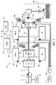
- Fig. 1 is a schematic diagram of an exemplary hybrid powertrain, in accordance with the present disclosure
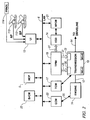
- Fig. 2 is a schematic diagram of an exemplary architecture for a control system and hybrid powertrain, in accordance with the present disclosure.
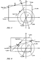
- Figs. 3 - 9 are graphical diagrams, in accordance with the present disclosure.
- FIGs. 1 and 2 depict an exemplary electro-mechanical hybrid powertrain.
- the exemplary electro-mechanical hybrid powertrain in accordance with the present disclosure is depicted in Fig. 1 , comprising a two-mode, compound-split, electro-mechanical hybrid transmission 10 operatively connected to an engine 14 and first and second electric machines ('MG-A') 56 and ('MG-B') 72.
- the engine 14 and first and second electric machines 56 and 72 each generate power which can be transferred to the transmission 10.
- the power generated by the engine 14 and the first and second electric machines 56 and 72 and transferred to the transmission 10 is described in terms of input and motor torques, referred to herein as T I , T A , and T B respectively, and speed, referred to herein as N I , N A , and N B , respectively.
- the exemplary engine 14 comprises a multi-cylinder internal combustion engine selectively operative in several states to transfer torque to the transmission 10 via an input shaft 12, and can be either a spark-ignition or a compression-ignition engine.
- the engine 14 includes a crankshaft (not shown) operatively coupled to the input shaft 12 of the transmission 10.
- a rotational speed sensor 11 monitors rotational speed of the input shaft 12.
- Power output from the engine 14, comprising rotational speed and engine torque can differ from the input speed N I and the input torque T I to the transmission 10 due to placement of torque-consuming components on the input shaft 12 between the engine 14 and the transmission 10, e.g., a hydraulic pump (not shown) and/or a torque management device (not shown).
- the exemplary transmission 10 comprises three planetary-gear sets 24, 26 and 28, and four selectively engageable torque-transferring devices, i.e., clutches C1 70, C2 62, C3 73, and C4 75.
- clutches refer to any type of friction torque transfer device including single or compound plate clutches or packs, band clutches, and brakes, for example.
- a hydraulic control circuit 42 preferably controlled by a transmission control module (hereafter 'TCM') 17, is operative to control clutch states.
- Clutches C2 62 and C4 75 preferably comprise hydraulically-applied rotating friction clutches.
- Clutches C1 70 and C3 73 preferably comprise hydraulically-controlled stationary devices that can be selectively grounded to a transmission case 68.
- Each of the clutches C1 70, C2 62, C3 73, and C4 75 is preferably hydraulically applied, selectively receiving pressurized hydraulic fluid via the hydraulic control circuit 42.
- the first and second electric machines 56 and 72 preferably comprise three-phase AC machines, each including a stator (not shown) and a rotor (not shown), and respective resolvers 80 and 82.
- the motor stator for each machine is grounded to an outer portion of the transmission case 68, and includes a stator core with coiled electrical windings extending therefrom.
- the rotor for the first electric machine 56 is supported on a hub plate gear that is operatively attached to shaft 60 via the second planetary gear set 26.
- the rotor for the second electric machine 72 is fixedly attached to a sleeve shaft hub 66.
- Each of the resolvers 80 and 82 preferably comprises a variable reluctance device including a resolver stator (not shown) and a resolver rotor (not shown).
- the resolvers 80 and 82 are appropriately positioned and assembled on respective ones of the first and second electric machines 56 and 72.
- Stators of respective ones of the resolvers 80 and 82 are operatively connected to one of the stators for the first and second electric machines 56 and 72.
- the resolver rotors are operatively connected to the rotor for the corresponding first and second electric machines 56 and 72.
- Each of the resolvers 80 and 82 is signally and operatively connected to a transmission power inverter control module (hereafter 'TPIM') 19, and each senses and monitors rotational position of the resolver rotor relative to the resolver stator, thus monitoring rotational position of respective ones of first and second electric machines 56 and 72. Additionally, the signals output from the resolvers 80 and 82 are interpreted to provide the rotational speeds for first and second electric machines 56 and 72, i.e., N A and N B , respectively.
- the transmission 10 includes an output member 64, e.g. a shaft, which is operably connected to a driveline 90 for a vehicle (not shown), to provide output power to the driveline 90 that is transferred to vehicle wheels 93, one of which is shown in Fig. 1 .
- the output power at the output member 64 is characterized in terms of an output rotational speed No and an output torque To.
- a transmission output speed sensor 84 monitors rotational speed and rotational direction of the output member 64.
- Each of the vehicle wheels 93 is preferably equipped with a sensor 94 adapted to monitor wheel speed, the output of which is monitored by a control module of a distributed control module system described with respect to Fig. 2 , to determine vehicle speed, and absolute and relative wheel speeds for braking control, traction control, and vehicle acceleration management.
- the input torque from the engine 14 and the motor torques from the first and second electric machines 56 and 72 (T I , T A , and T B respectively) are generated as a result of energy conversion from fuel or electrical potential stored in an electrical energy storage device (hereafter 'ESD') 74.
- the ESD 74 is high voltage DC-coupled to the TPIM 19 via DC transfer conductors 27.
- the transfer conductors 27 include a contactor switch 38. When the contactor switch 38 is closed, under normal operation, electric current can flow between the ESD 74 and the TPIM 19. When the contactor switch 38 is opened electric current flow between the ESD 74 and the TPIM 19 is interrupted.
- the TPIM 19 transmits electrical power to and from the first electric machine 56 by transfer conductors 29, and the TPIM 19 similarly transmits electrical power to and from the second electric machine 72 by transfer conductors 31 to meet the torque commands for the first and second electric machines 56 and 72 in response to the motor torques T A and T B . Electrical current is transmitted to and from the ESD 74 in accordance with whether the ESD 74 is being charged or discharged.
- the TPIM 19 includes the pair of power inverters (not shown) and respective motor control modules (not shown) configured to receive the torque commands and control inverter states therefrom for providing motor drive or regeneration functionality to meet the commanded motor torques T A and T B .
- the power inverters comprise known complementary three-phase power electronics devices, and each includes a plurality of insulated gate bipolar transistors (not shown) for converting DC power from the ESD 74 to AC power for powering respective ones of the first and second electric machines 56 and 72, by switching at high frequencies.
- the insulated gate bipolar transistors form a switch mode power supply configured to receive control commands. There is typically one pair of insulated gate bipolar transistors for each phase of each of the three-phase electric machines.
- the three-phase inverters receive or supply DC electric power via DC transfer conductors 27 and transform it to or from three-phase AC power, which is conducted to or from the first and second electric machines 56 and 72 for operation as motors or generators via transfer conductors 29 and 31 respectively.
- Fig. 2 is a schematic block diagram of the distributed control module system.
- the elements described hereinafter comprise a subset of an overall vehicle control architecture, and provide coordinated system control of the exemplary hybrid powertrain described in Fig. 1 .
- the distributed control module system synthesizes pertinent information and inputs, and executes algorithms to control various actuators to meet control objectives, including objectives related to fuel economy, emissions, performance, drivability, and protection of hardware, including batteries of ESD 74 and the first and second electric machines 56 and 72.
- the distributed control module system includes an engine control module (hereafter 'ECM') 23, the TCM 17, a battery pack control module (hereafter 'BPCM') 21, and the TPIM 19.
- 'ECM' engine control module
- TCM 17 battery pack control module
- TPIM 19 battery pack control module
- a hybrid control module (hereafter 'HCP') 5 provides supervisory control and coordination of the ECM 23, the TCM 17, the BPCM 21, and the TPIM 19.
- a user interface ('UI') 13 is signally connected to a plurality of devices through which a vehicle operator controls or directs operation of the electro-mechanical hybrid powertrain.
- the devices include an accelerator pedal 113 ('AP'), an operator brake pedal 112 ('BP'), a transmission gear selector 114 ('PRNDL'), and a vehicle speed cruise control (not shown).
- the transmission gear selector 114 may have a discrete number of operator-selectable positions, including the rotational direction of the output member 64 to enable one of a forward and a reverse direction.
- the aforementioned control modules communicate with other control modules, sensors, and actuators via a local area network (hereafter 'LAN') bus 6.
- the LAN bus 6 allows for structured communication of states of operating parameters and actuator command signals between the various control modules.
- the specific communication protocol utilized is application-specific.
- the LAN bus 6 and appropriate protocols provide for robust messaging and multi-control module interfacing between the aforementioned control modules, and other control modules providing functionality including e.g., antilock braking, traction control, and vehicle stability.
- Multiple communications buses may be used to improve communications speed and provide some level of signal redundancy and integrity. Communication between individual control modules can also be effected using a direct link, e.g., a serial peripheral interface ('SPI') bus (not shown).
- 'SPI' serial peripheral interface
- the HCP 5 provides supervisory control of the hybrid powertrain, serving to coordinate operation of the ECM 23, TCM 17, TPIM 19, and BPCM 21. Based upon various input signals from the user interface 13 and the hybrid powertrain, including the ESD 74, the HCP 5 determines an operator torque request, an output torque command, an engine input torque command, clutch torque(s) for the applied torque-transfer clutches C1 70, C2 62, C3 73, C4 75 of the transmission 10, and the motor torques T A and T B for the first and second electric machines 56 and 72.
- the TCM 17 is operatively connected to the hydraulic control circuit 42 and provides various functions including monitoring various pressure sensing devices (not shown) and generating and communicating control signals to various solenoids (not shown) thereby controlling pressure switches and control valves contained within the hydraulic control circuit 42.
- the ECM 23 is operatively connected to the engine 14, and functions to acquire data from sensors and control actuators of the engine 14 over a plurality of discrete lines, shown for simplicity as an aggregate bidirectional interface cable 35.
- the ECM 23 receives the engine input torque command from the HCP 5.
- the ECM 23 determines the actual engine input torque, T I , provided to the transmission 10 at that point in time based upon monitored engine speed and load, which is communicated to the HCP 5.
- the ECM 23 monitors input from the rotational speed sensor 11 to determine the engine input speed to the input shaft 12, which translates to the transmission input speed, N I .
- the ECM 23 monitors inputs from sensors (not shown) to determine states of other engine operating parameters including, e.g., a manifold pressure, engine coolant temperature, ambient air temperature, and ambient pressure.
- the engine load can be determined, for example, from the manifold pressure, or alternatively, from monitoring operator input to the accelerator pedal 113.
- the ECM 23 generates and communicates command signals to control engine actuators, including, e.g., fuel injectors, ignition modules, and throttle control modules, none of which are shown.
- the TCM 17 is operatively connected to the transmission 10 and monitors inputs from sensors (not shown) to determine states of transmission operating parameters.
- the TCM 17 generates and communicates command signals to control the transmission 10, including controlling the hydraulic circuit 42.
- Inputs from the TCM 17 to the HCP 5 include estimated clutch torques for each of the clutches, i.e., C1 70, C2 62, C3 73, and C4 75, and rotational output speed, No, of the output member 64.
- Other actuators and sensors may be used to provide additional information from the TCM 17 to the HCP 5 for control purposes.
- the TCM 17 monitors inputs from pressure switches (not shown) and selectively actuates pressure control solenoids (not shown) and shift solenoids (not shown) of the hydraulic circuit 42 to selectively actuate the various clutches C1 70, C2 62, C3 73, and C4 75 to achieve various transmission operating range states, as described hereinbelow.
- the BPCM 21 is signally connected to sensors (not shown) to monitor the ESD 74, including states of electrical current and voltage parameters, to provide information indicative of parametric states of the batteries of the ESD 74 to the HCP 5.
- the parametric states of the batteries preferably include battery state-of-charge, battery voltage, battery temperature, and available battery power, referred to as a range P BAT_MIN to P BAT_MAX .
- a brake control module (hereafter 'BrCM') 22 is operatively connected to friction brakes (not shown) on each of the vehicle wheels 93.
- the BrCM 22 monitors the operator input to the brake pedal 112 and generates control signals to control the friction brakes and sends a control signal to the HCP 5 to operate the first and second electric machines 56 and 72 based thereon.
- Each of the control modules ECM 23, TCM 17, TPIM 19, BPCM 21, and BrCM 22 is preferably a general-purpose digital computer comprising a microprocessor or central processing unit, storage mediums comprising read only memory ('ROM'), random access memory ('RAM'), electrically programmable read only memory ('EPROM'), a high speed clock, analog to digital ('A/D') and digital to analog ('D/A') circuitry, and input/output circuitry and devices ('I/O') and appropriate signal conditioning and buffer circuitry.
- Each of the control modules has a set of control algorithms, comprising resident program instructions and calibrations stored in one of the storage mediums and executed to provide the respective functions of each computer.
- control algorithms are executed during preset loop cycles such that each algorithm is executed at least once each loop cycle.
- Algorithms stored in the non-volatile memory devices are executed by one of the central processing units to monitor inputs from the sensing devices and execute control and diagnostic routines to control operation of the actuators, using preset calibrations.
- Loop cycles are executed at regular intervals, for example each 3.125, 6.25, 12.5, 25 and 100 milliseconds during ongoing operation of the hybrid powertrain.
- algorithms may be executed in response to the occurrence of an event.
- the exemplary hybrid powertrain selectively operates in one of several operating range states that can be described in terms of an engine state comprising one of an engine-on state ('ON') and an engine-off state ('OFF'), and a transmission state comprising a plurality of fixed gears and continuously variable operating modes, described with reference to Table 1, below.
- Each of the transmission operating range states is described in the table and indicates which of the specific clutches C1 70, C2 62, C3 73, and C4 75 are applied for each of the operating range states.
- a first continuously variable mode i.e., EVT Mode 1, or M1 is selected by applying clutch C1 70 only in order to "ground” the outer gear member of the third planetary gear set 28.
- the engine state can be one of ON ('M1_Eng_On') or OFF ('M1_Eng_Off').
- a second continuously variable mode i.e., EVT Mode 2, or M2, is selected by applying clutch C2 62 only to connect the shaft 60 to the carrier of the third planetary gear set 28.
- the engine state can be one of ON ('M2_Eng_On') or OFF ('M2_Eng_Off').
- 'RPM' revolutions per minute
- a fixed gear operation provides a fixed ratio operation of input-to-output speed of the transmission 10, i.e., N I /N O .
- a first fixed gear operation ('G1') is selected by applying clutches C1 70 and C4 75.
- a second fixed gear operation ('G2') is selected by applying clutches C1 70 and C2 62.
- a third fixed gear operation ('G3') is selected by applying clutches C2 62 and C4 75.
- a fourth fixed gear operation ('G4') is selected by applying clutches C2 62 and C3 73.
- the fixed ratio operation of input-to-output speed increases with increased fixed gear operation due to decreased gear ratios in the planetary gears 24, 26, and 28.
- the rotational speeds of the first and second electric machines 56 and 72, N A and N B respectively, are dependent on internal rotation of the mechanism as defined by the clutching and are proportional to the input speed measured at the input shaft 12.
- the HCP 5 and one or more of the other control modules determine torque commands to control the torque generative devices comprising the engine 14 and first and second electric machines 56 and 72 to meet the operator torque request at the output member 64 and transferred to the driveline 90.
- the HCP 5 determines the operator torque request, a commanded output torque between the transmission 10 and the driveline 90, an input torque from the engine 14, clutch torques for the torque-transfer clutches C1 70, C2 62, C3 73, C4 75 of the transmission 10; and the motor torques for the first and second electric machines 56 and 72, respectively, as is described hereinbelow.
- the commanded output torque can be a tractive torque wherein torque flow originates in the engine 14 and the first and second electric machines 56 and 72 and is transferred through the transmission 10 to the driveline 90, and can be a reactive torque wherein torque flow originates in the vehicle wheels 93 of the driveline 90 and is transferred through the transmission 10 to first and second electric machines 56 and 72 and the engine 14.
- the operating range state is determined for the transmission 10 based upon a variety of operating characteristics of the hybrid powertrain. This includes the operator torque request communicated through the accelerator pedal 113 and brake pedal 112 to the user interface 13 as previously described.
- the operating range state may be predicated on a hybrid powertrain torque demand caused by a command to operate the first and second electric machines 56 and 72 in an electrical energy generating mode or in a torque generating mode.
- the operating range state can be determined by an optimization algorithm or routine which determines optimum system efficiency based upon operator demand for power, battery state of charge, and energy efficiencies of the engine 14 and the first and second electric machines 56 and 72.
- the control system manages torque inputs from the engine 14 and the first and second electric machines 56 and 72 based upon an outcome of the executed optimization routine, and system efficiencies are optimized thereby, to manage fuel economy and battery charging. Furthermore, operation can be determined based upon a fault in a component or system.
- the HCP 5 monitors the torque-generative devices, and determines the power output from the transmission 10 required in response to the desired output torque at output member 64 to meet the operator torque request.
- the ESD 74 and the first and second electric machines 56 and 72 are electrically-operatively coupled for power flow therebetween.
- the engine 14, the first and second electric machines 56 and 72, and the electro-mechanical transmission 10 are mechanically-operatively coupled to transfer power therebetween to generate a power flow to the output member 64.
- Operation of the engine 14 and transmission 10 is constrained by power, torque and speed limits of the engine 14, the first and second electric machines 56 and 72, the ESD 74 and the clutches C1 70, C2 62, C3 73, and C4 75.
- the operating constraints on the engine 14 and transmission 10 can be translated to a set of system constraint equations executed as one or more algorithms in one of the control modules, e.g., the HCP 5.
- the transmission 10 operates in one of the operating range states through selective actuation of one or two of the torque-transfer clutches.
- Torque constraints for each of the engine 14 and the first and second electric machines 56 and 72 and speed constraints for each of the engine 14, the first and second electric machines 56 and 72, and the output shaft 64 of the transmission 10 are determined.
- Battery power constraints for the ESD 74 are determined, and are applied to further limit the motor torque constraints for the first and second electrical machines 56 and 72.
- the preferred operating region for the powertrain is determined using the system constraint equation, based upon the battery power constraints, the motor torque constraints, and the speed constraints.
- the preferred operating region comprises a range of permissible operating torques or speeds for the engine 14 and the first and second electric machines 56 and 72.
- T M ⁇ 1 T A ⁇ to T M ⁇ 1 * T A + T B ⁇ to T M ⁇ 1 * T B + Misc_T M ⁇ 1
- T M ⁇ 2 T A ⁇ to T M ⁇ 2 * T A + T B ⁇ to T M ⁇ 2 * T B + Misc_T M ⁇ 2
- T M ⁇ 3 T A ⁇ to T M ⁇ 3 * T A + T B ⁇ to T M ⁇ 3 * T B + Misc_T M ⁇ 3
- T M1 represents the output torque To at output member 64
- T M2 represents the input torque T 1 at input shaft 12
- T M3 represents the reactive clutch torque(s) for the applied torque-transfer clutches C1 70, C2 62, C3 73, C4 75 of the transmission 10
- the engine 14 and transmission 10 and the first and second electric machines 56 and 72 have speed constraints, torque constraints, and battery power constraints due to mechanical and system limitations.
- the speed constraints for the first and second electric machines 56 and 72 can be as follows: - 10 , 500 rpm ⁇ N A ⁇ + 10 , 500 rpm , and - 10 , 500 rpm ⁇ N B ⁇ + 10 , 500 rpm .
- the torque constraints include engine torque constraints including T I_MIN ⁇ T I ⁇ T I_MAX , and motor torque constraints for the first and second electric machines including T A_MIN ⁇ T A ⁇ T A_MAX and T B_MIN ⁇ T B ⁇ T B_MAX .
- the motor torque constraints T A_MAX and T A_MIN comprise torque limits for the first electric machine 56 when working as a torque-generative motor and an electrical generator, respectively.
- the motor torque constraints T B_MAX and T B_MIN comprise torque limits for the second electric machine 72 when working as a torque-generative motor and an electrical generator, respectively.
- the maximum and minimum motor torque constraints T A_MAX , T A_MIN , T B_MAX , T B_MIN are preferably obtained from data sets stored in tabular format within one of the memory devices of one of the control modules. Such data sets are empirically derived from conventional dynamometer testing of the combined motor and power electronics (e.g., power inverter) at various temperature and voltage conditions.
- Battery power constraints comprise the available battery power within the range of P BAT_MIN to P BAT_MAX , wherein P BAT_MIN is maximum allowable battery charging power and P BAT_MAX is the maximum allowable battery discharging power. Battery power is defined as positive when discharging and negative when charging.
- Minimum and maximum values for T M1 are determined within the speed constraints, the motor torque constraints, clutch torque constraints, and the battery power constraints during ongoing operation, in order to control operation of the engine 14, the first and second electric machines 56 and 72, also referred to hereinafter as Motor A 56 and Motor B 72, and the transmission 10 to meet the operator torque request and the commanded output torque.
- P BAT P A , ELEC + P B , ELEC + P DC_LOAD wherein P A,ELEC comprises electrical power from Motor A 56, P B,ELEC comprises electrical power from Motor B 72, and P DC_LOAD comprises known DC load, including accessory loads.
- Eq. 5 can be restated as Eq. 6, below, wherein speeds, N A and N B , and torques, T A and T B , are substituted for powers P A and P B .
- This includes an assumption that motor and inverter losses can be mathematically modeled as a quadratic equation based upon torque as follows: P BAT N A ⁇ T A + a 1 N A ⁇ T A 2 + a 2 N A ⁇ T A + a 3 N A + N B ⁇ T B + b 1 N B ⁇ T B 2 + b 3 N B + P DC_LOAD
- N A , N B comprise speeds of Motors A and B 56 and 72
- T A , T B comprise torques of Motors A and B 56 and 72
- a1, a2, a3, b1, b2, b3 each comprise quadratic coefficients which are a function of respective motor speeds, N A , N B .
- Eq. 12 specifies the transformation of motor torque T A to T X and the transformation of motor torque T B to T Y .
- the minimum and maximum battery powers, P BAT_MIN and P BAT_MAX are preferably correlated to battery physics, e.g. state of charge, temperature, voltage and usage (amp-hour/hour).
- the positive sign ('+') is defined as discharging power from the ESD 74, and the negative sign ('-') is defined as charging power into the ESD 74.
- R Max defines a maximum battery power, typically a discharging power
- R Min defines a maximum battery charging power.
- the limit torque T M1 comprises the output torque To in this embodiment, Eqs. 1, 2, and 3 restated in the T X /T Y space are as follows.
- T M ⁇ 1 T A ⁇ to T M ⁇ 1 * T X - A 2 / A 1 + T B ⁇ to T M ⁇ 1 * T Y - B 2 / B 1 + Misc_T M ⁇ 1
- T M ⁇ 2 T A ⁇ to T M ⁇ 2 * T X - A 2 / A 1 + T B ⁇ to T M ⁇ 2 * T Y - B 2 / B 1 + Misc_T M ⁇ 2
- T M ⁇ 3 T A ⁇ to T M ⁇ 3 * T X - A 2 / A 1 + T B ⁇ to T M ⁇ 3 * T Y - B 2 / B 1 + Misc_T M ⁇ 3
- T X ⁇ toT M ⁇ 1 T A ⁇ toT M ⁇ 1 / A 1
- T Y ⁇ toT M ⁇ 1 T B ⁇ toT M ⁇ 1 / B 1
- T M ⁇ 1 _ ⁇ Intercept T A ⁇ toT M ⁇ 1 * A 2 / A 1 + T B ⁇ toT M ⁇ 1 * B 2 / B 1
- T X ⁇ toT M ⁇ 2 T A ⁇ toT M ⁇ 2 / A 1
- T Y ⁇ toT M ⁇ 2 T B ⁇ toT M ⁇ 2 / B 1
- T M ⁇ 2 _ ⁇ Intercept T A ⁇ toT M ⁇ 2 * A 2 / A 1 + T B ⁇ toT M ⁇ 2 * B 2 / B 1
- T M ⁇ 1 _XY T X ⁇ to T M ⁇ 1 * T X + T Y ⁇ to T M ⁇ 1 * T Y + T M ⁇ 1 _ ⁇ Intercept
- T M ⁇ 2 _XY T X ⁇ to T M ⁇ 2 * T X + T Y ⁇ to T M ⁇ 2 * T Y + T M ⁇ 2 _ ⁇ Intercept
- T M ⁇ 3 _XY T X ⁇ to T M ⁇ 3 * T X + T Y ⁇ to T M ⁇ 3 * T Y + T M ⁇ 3 _ ⁇ Intercept
- Eq. 21 comprises a limit torque function describing the output torque constraint T M1 , e.g., To.
- the torque limit of the transmission 10, in this embodiment the output torque To can be determined by using Eq. 21 subject to the T M2 and T M3 constraints defined by Eqs. 22 and 23to determine a transformed maximum or minimum limit torque in the T X /T Y space, comprising one of T M1_XY Max and T M1_XY Min, e.g., maximum and minimum output torques T O_Max and T O_Min that have been transformed. Subsequently the transformed maximum or minimum limit torque in the T X /T Y space can be retransformed out of the T X /T Y space to determine maximum or minimum limit torques T M1_ Max and T M1_ Min for managing control and operation of the transmission 14 and the first and second electric machines 56 and 72.
- motor torque constraints are shown comprising the transformed minimum and maximum motor torques for T A and T B transformed to T X /T Y space ('Tx_Min', 'Tx_Max', 'Ty_Min', 'Ty_Max').
- Tm ⁇ 1 a * Tx + b * Ty + C wherein a ⁇ 0, b > 0, and C is a constant term.
- the line T M1_XY has a positive slope of 1:1 for purposes of illustration.
- the additional constraint line T M2_XY comprises the input torque T I in this embodiment.
- the additional constraint line T M2_XY can comprise the clutch torque or another constraint.
- Fig. 4 graphically shows a first case wherein battery power at the point of the transformed minimum motor torque T A ('Tx_Min') and the transformed maximum motor torque T B ('Ty_Max') is greater than the transformed maximum battery power ('R_Max').
- the battery power constraints are less than sufficient to meet a required battery power for achieving the maximum output torque based upon the motor torque constraints.
- a second line is generated perpendicular to the additional constraint line T M2_XY and passing through the center locus point K, designated as line L3L4, and intersects the additional constraint line T M2_XY at point Q.
- Point Q identifies the point on the additional constraint line T M2_XY that minimizes violation of the battery power constraints.
- Point Q is within the motor torque constraints comprising the transformed minimum and maximum motor torques for T A and T B ('Tx_Min', 'Tx_Max', 'Ty_Min', 'Ty_Max').
- the preferred solution for this set of constraints is the Point Q which meets the additional constraint T M2_XY and has the least violation of the battery power constraint.
- the solution set preferably comprises a (Tx, Ty) point representing a preferred solution for controlling operation that can be retransformed to motor torques (T A , T B ) to control operation of the first and second electric machines 56 and 72.
- Fig. 5 graphically shows a second case wherein battery power at the point of the transformed minimum motor torque T A ('Tx_Min') and the transformed maximum motor torque T B ('Ty_Max') is greater than the transformed maximum battery power ('R_Max').
- the battery power constraints are less than sufficient to meet a required battery power for achieving the maximum output torque based upon the motor torque constraints.
- a second line is generated perpendicular to the additional constraint line T M2_XY and passing through the center locus point K, designated as line L3L4, which intersects the additional constraint line T M2_XY at point Q.
- Point Q identifies the point on the additional constraint line T M2_XY which minimizes violation of the battery power constraints.
- Point Q is outside the motor torque constraints comprising the transformed minimum and maximum motor torques for T A and T B ('Tx_Min', 'Tx_Max', 'Ty_Min', 'Ty_Max').
- the L1L2 line segment represents the limits at which the solution meets the additional constraint line T M2_XY and the motor torque constraints.
- Point Q is the optimal solution, however, it falls outside the boundaries of the L1L2 line segment.
- Point R is set to the L2 point of the L1L2 line segment since it is the closest point in the L1L2 line segment to the optimal solution Q.
- the preferred solution for this set of constraints is Point R which meets the T M2 constraint and has the least violation of the battery power constraint.
- the solution set comprises a (Tx, Ty) point representing the preferred solution Point R for controlling operation that can be retransformed to motor torques (T A , T B ) to control operation of the first and second electric machines 56 and 72.
- Fig. 6 graphically shows a third case wherein battery power at the point of the transformed minimum motor torque T A ('Tx_Min') and the transformed maximum motor torque T B ('Ty_Max') is greater than the transformed maximum battery power ('R_Max').
- the battery power constraints are less than sufficient to meet a required battery power for achieving the maximum output torque based upon the motor torque constraints.
- a line segment L3L4 is defined as points on the additional constraint line T M2_XY , wherein points L3 and L4 define intersections of the additional constraint line T M2_XY and the transformed maximum battery power.
- Point Q is within the motor torque constraints comprising the transformed minimum and maximum motor torques for T A and T B ('Tx_Min', 'Tx_Max', 'Ty_Min', 'Ty_Max'), but is outside of the battery power constraints. Therefore, the preferred solution for this set of constraints is Point R, which is the point whereat the additional constraint line T M2_XY intersects the transformed maximum battery power ('R_Max'), i.e., Point L3.
- the solution set consists of the (Tx, Ty) point representing the preferred solution for controlling operation that can be retransformed to motor torques (T A , T B ) to control operation of the first and second electric machines 56 and 72.
- the preferred output torque is constrained based upon the battery torque.
- Fig. 7 graphically shows a fourth case wherein battery power at the point of the transformed minimum motor torque T A ('Tx_Min') and the transformed maximum motor torque T B ('Ty_Max') is greater than the transformed maximum battery power ('R_Max').
- the battery power constraints are less than sufficient to meet a required battery power for achieving the maximum output torque based upon the motor torque constraints.
- a line segment L3L4 is defined as points on the additional constraint line T M2_XY , wherein points L3 and L4 define intersections of the additional constraint line T M2_XY and the transformed maximum battery power.
- line segment L3L4 There is some overlap between line segment L3L4 and line segment L1L2.
- Point Q is within the motor torque constraints comprising the transformed minimum and maximum motor torques for T A and T B ('Tx_Min', 'Tx_Max', 'Ty_Min', 'Ty_Max'), but is outside the battery power constraints.
- the L3L2 line segment represents the limits at which the solution meets T M2 and the motor torque constraints.
- Point Q is the optimal solution, however, it falls outside the boundaries of the L3L2 line segment.
- Point R is set equal to the L3 point of the line segment since it is the closest point in the segment to the optimal solution Q.
- the preferred solution for this set of constraints is the Point R that meets the additional constraint line T M2_XY and maximizes the output torque.
- the solution set consists of the (Tx, Ty) point representing the preferred solution for controlling operation that can be retransformed to motor torques (T A , T B ) to control operation of the first and second electric machines 56 and 72.
- the preferred output torque is constrained based upon the battery torque.
- Fig. 8 graphically shows a fifth case wherein battery power at the point of the transformed minimum motor torque T A ('Tx_Min') and the transformed maximum motor torque T B ('Ty_Max') is greater than the transformed maximum battery power ('R_Max').
- the battery power constraints are less than sufficient to meet a required battery power for achieving the maximum output torque based upon the motor torque constraints.
- a line segment L3L4 is defined as points on the additional constraint line T M2_XY , wherein points L3 and L4 define intersections of the additional constraint line T M2_XY and the transformed maximum battery power.
- Point Q is outside the motor torque constraints comprising the transformed minimum and maximum motor torques for T A and T B ('Tx_Min', 'Tx_Max', 'Ty_Min', 'Ty_Max'), but is within the battery power constraints.
- Point P defines a maximum point whereat the battery power constraints intersect the motor torque constraints, but does not satisfy the additional constraint line T M2_XY .
- Point R is set equal to the L2 point of the line segment since it is the closest point in the segment to the optimal solution Q.
- the preferred solution for this set of constraints is Point R that satisfies the motor torque constraints and the additional constraint line T M2_XY and has the least violation of the battery power constraints.
- the solution set consists of the (Tx, Ty) point representing the preferred solution for controlling operation that can be retransformed to motor torques (T A , T B ) to control operation of the first and second electric machines 56 and 72.
- the preferred output torque is constrained based upon the battery torque.
- a first line segment X3X4 is defined as existing between X3 and X4; a second line segment X1X2 is defined as existing between X1 and X2; a third line segment XLXS is defined as existing between points XL and XS; and a fourth line segment X2XL is defined as existing between points X2 and XL.
- the first output torque constraint ('Tm1') is not depicted. When the first output torque constraint intersects with one of the first line segment X3X4 and the fourth line segment X2XL, the preferred solution is the point on the additional constraint line T M2_XY whereat the first output torque constraint intersects the line segment (not shown).
- the preferred solution is the one of points X4, X3, X2 and XL that is closest in proximity to the first output torque constraint (not shown).
- a (Tx, Ty) coordinate represents the preferred solution for controlling operation that can be retransformed to motor torques (T A , T B ) to control operation of the first and second electric machines 56 and 72.
- the preferred output torque is constrained based upon the battery torque.
- Tm ⁇ 1 a * Tx + b * Ty + C
- the description is applicable to combinations of a > 0, b ⁇ 0, and the slope of a/b being less than 1:1 and being greater than 1:1.
Description
- This disclosure pertains to control systems for hybrid powertrain systems. In particular, the invention relates to a method for controlling an electro-mechanical transmission in accordance with the preamble of claim 1, as it is known from
US 2005/0252305 A1 , e.g.. - The statements in this section merely provide background information related to the present disclosure and may not constitute prior art.
- Known hybrid powertrain architectures can include multiple torque-generative devices, including internal combustion engines and non-combustion machines, e.g., electric machines, which transmit torque through a transmission device to an output member. One exemplary hybrid powertrain includes a two-mode, compound-split, electro-mechanical transmission which utilizes an input member for receiving tractive torque from a prime mover power source, preferably an internal combustion engine, and an output member. The output member can be operatively connected to a driveline for a motor vehicle for transmitting tractive torque thereto. Machines, operative as motors or generators, can generate torque inputs to the transmission independently of a torque input from the internal combustion engine. The machines may transform vehicle kinetic energy transmitted through the vehicle driveline to energy that is storable in an energy storage device. A control system monitors various inputs from the vehicle and the operator and provides operational control of the hybrid powertrain, including controlling transmission operating state and gear shifting, controlling the torque-generative devices, and regulating the power interchange among the energy storage device and the machines to manage outputs of the transmission, including torque and rotational speed.
- An electro-mechanical transmission is operatively coupled to first and second electric machines to transmit power to an output member. A method for controlling operation of the electro-mechanical transmission includes determining motor torque constraints for the first and second electric machines and battery power constraints for an electrical energy storage device electrically connected to the first and second electric machines. An additional constraint on the electro-mechanical transmission is determined. A preferred output torque to the output member of the electro-mechanical transmission that is achievable within the motor torque constraints and is based upon the additional constraint and the battery power constraints is determined when battery power constraints are less than sufficient to meet a required power for achieving a maximum output torque based upon the motor torque constraints. Operation of the electro-mechanical transmission and the first and second electric machines is controlled to achieve the preferred output torque at the output member based upon the motor torque constraints, the additional constraint, and the battery power constraints.
- One or more embodiments will now be described, by way of example, with reference to the accompanying drawings, in which:
-
Fig. 1 is a schematic diagram of an exemplary hybrid powertrain, in accordance with the present disclosure; -
Fig. 2 is a schematic diagram of an exemplary architecture for a control system and hybrid powertrain, in accordance with the present disclosure; and -
Figs. 3 - 9 are graphical diagrams, in accordance with the present disclosure. - Referring now to the drawings, wherein the showings are for the purpose of illustrating certain exemplary embodiments only and not for the purpose of limiting the same,
Figs. 1 and2 depict an exemplary electro-mechanical hybrid powertrain. The exemplary electro-mechanical hybrid powertrain in accordance with the present disclosure is depicted inFig. 1 , comprising a two-mode, compound-split, electro-mechanical hybrid transmission 10 operatively connected to anengine 14 and first and second electric machines ('MG-A') 56 and ('MG-B') 72. Theengine 14 and first and secondelectric machines transmission 10. The power generated by theengine 14 and the first and secondelectric machines transmission 10 is described in terms of input and motor torques, referred to herein as TI, TA, and TB respectively, and speed, referred to herein as NI, NA, and NB, respectively. - The
exemplary engine 14 comprises a multi-cylinder internal combustion engine selectively operative in several states to transfer torque to thetransmission 10 via aninput shaft 12, and can be either a spark-ignition or a compression-ignition engine. Theengine 14 includes a crankshaft (not shown) operatively coupled to theinput shaft 12 of thetransmission 10. Arotational speed sensor 11 monitors rotational speed of theinput shaft 12. Power output from theengine 14, comprising rotational speed and engine torque, can differ from the input speed NI and the input torque TI to thetransmission 10 due to placement of torque-consuming components on theinput shaft 12 between theengine 14 and thetransmission 10, e.g., a hydraulic pump (not shown) and/or a torque management device (not shown). - The
exemplary transmission 10 comprises three planetary-gear sets clutches C1 70,C2 62,C3 73, andC4 75. As used herein, clutches refer to any type of friction torque transfer device including single or compound plate clutches or packs, band clutches, and brakes, for example. Ahydraulic control circuit 42, preferably controlled by a transmission control module (hereafter 'TCM') 17, is operative to control clutch states.Clutches C2 62 andC4 75 preferably comprise hydraulically-applied rotating friction clutches.Clutches C1 70 andC3 73 preferably comprise hydraulically-controlled stationary devices that can be selectively grounded to atransmission case 68. Each of theclutches C1 70,C2 62,C3 73, andC4 75 is preferably hydraulically applied, selectively receiving pressurized hydraulic fluid via thehydraulic control circuit 42. - The first and second
electric machines respective resolvers transmission case 68, and includes a stator core with coiled electrical windings extending therefrom. The rotor for the firstelectric machine 56 is supported on a hub plate gear that is operatively attached toshaft 60 via the secondplanetary gear set 26. The rotor for the secondelectric machine 72 is fixedly attached to asleeve shaft hub 66. - Each of the
resolvers resolvers electric machines resolvers electric machines electric machines resolvers electric machines resolvers electric machines - The
transmission 10 includes anoutput member 64, e.g. a shaft, which is operably connected to adriveline 90 for a vehicle (not shown), to provide output power to thedriveline 90 that is transferred tovehicle wheels 93, one of which is shown inFig. 1 . The output power at theoutput member 64 is characterized in terms of an output rotational speed No and an output torque To. A transmissionoutput speed sensor 84 monitors rotational speed and rotational direction of theoutput member 64. Each of thevehicle wheels 93 is preferably equipped with asensor 94 adapted to monitor wheel speed, the output of which is monitored by a control module of a distributed control module system described with respect toFig. 2 , to determine vehicle speed, and absolute and relative wheel speeds for braking control, traction control, and vehicle acceleration management. - The input torque from the
engine 14 and the motor torques from the first and secondelectric machines 56 and 72 (TI, TA, and TB respectively) are generated as a result of energy conversion from fuel or electrical potential stored in an electrical energy storage device (hereafter 'ESD') 74. The ESD 74 is high voltage DC-coupled to the TPIM 19 viaDC transfer conductors 27. Thetransfer conductors 27 include acontactor switch 38. When thecontactor switch 38 is closed, under normal operation, electric current can flow between theESD 74 and theTPIM 19. When thecontactor switch 38 is opened electric current flow between theESD 74 and the TPIM 19 is interrupted. TheTPIM 19 transmits electrical power to and from the firstelectric machine 56 bytransfer conductors 29, and theTPIM 19 similarly transmits electrical power to and from the secondelectric machine 72 bytransfer conductors 31 to meet the torque commands for the first and secondelectric machines ESD 74 in accordance with whether theESD 74 is being charged or discharged. - The TPIM 19 includes the pair of power inverters (not shown) and respective motor control modules (not shown) configured to receive the torque commands and control inverter states therefrom for providing motor drive or regeneration functionality to meet the commanded motor torques TA and TB. The power inverters comprise known complementary three-phase power electronics devices, and each includes a plurality of insulated gate bipolar transistors (not shown) for converting DC power from the
ESD 74 to AC power for powering respective ones of the first and secondelectric machines DC transfer conductors 27 and transform it to or from three-phase AC power, which is conducted to or from the first and secondelectric machines transfer conductors -
Fig. 2 is a schematic block diagram of the distributed control module system. The elements described hereinafter comprise a subset of an overall vehicle control architecture, and provide coordinated system control of the exemplary hybrid powertrain described inFig. 1 . The distributed control module system synthesizes pertinent information and inputs, and executes algorithms to control various actuators to meet control objectives, including objectives related to fuel economy, emissions, performance, drivability, and protection of hardware, including batteries ofESD 74 and the first and secondelectric machines TCM 17, a battery pack control module (hereafter 'BPCM') 21, and theTPIM 19. A hybrid control module (hereafter 'HCP') 5 provides supervisory control and coordination of theECM 23, theTCM 17, theBPCM 21, and theTPIM 19. A user interface ('UI') 13 is signally connected to a plurality of devices through which a vehicle operator controls or directs operation of the electro-mechanical hybrid powertrain. The devices include an accelerator pedal 113 ('AP'), an operator brake pedal 112 ('BP'), a transmission gear selector 114 ('PRNDL'), and a vehicle speed cruise control (not shown). Thetransmission gear selector 114 may have a discrete number of operator-selectable positions, including the rotational direction of theoutput member 64 to enable one of a forward and a reverse direction. - The aforementioned control modules communicate with other control modules, sensors, and actuators via a local area network (hereafter 'LAN')
bus 6. TheLAN bus 6 allows for structured communication of states of operating parameters and actuator command signals between the various control modules. The specific communication protocol utilized is application-specific. TheLAN bus 6 and appropriate protocols provide for robust messaging and multi-control module interfacing between the aforementioned control modules, and other control modules providing functionality including e.g., antilock braking, traction control, and vehicle stability. Multiple communications buses may be used to improve communications speed and provide some level of signal redundancy and integrity. Communication between individual control modules can also be effected using a direct link, e.g., a serial peripheral interface ('SPI') bus (not shown). - The
HCP 5 provides supervisory control of the hybrid powertrain, serving to coordinate operation of theECM 23,TCM 17,TPIM 19, andBPCM 21. Based upon various input signals from theuser interface 13 and the hybrid powertrain, including theESD 74, theHCP 5 determines an operator torque request, an output torque command, an engine input torque command, clutch torque(s) for the applied torque-transfer clutches C1 70,C2 62,C3 73,C4 75 of thetransmission 10, and the motor torques TA and TB for the first and secondelectric machines TCM 17 is operatively connected to thehydraulic control circuit 42 and provides various functions including monitoring various pressure sensing devices (not shown) and generating and communicating control signals to various solenoids (not shown) thereby controlling pressure switches and control valves contained within thehydraulic control circuit 42. - The
ECM 23 is operatively connected to theengine 14, and functions to acquire data from sensors and control actuators of theengine 14 over a plurality of discrete lines, shown for simplicity as an aggregatebidirectional interface cable 35. TheECM 23 receives the engine input torque command from theHCP 5. TheECM 23 determines the actual engine input torque, TI, provided to thetransmission 10 at that point in time based upon monitored engine speed and load, which is communicated to theHCP 5. TheECM 23 monitors input from therotational speed sensor 11 to determine the engine input speed to theinput shaft 12, which translates to the transmission input speed, NI. TheECM 23 monitors inputs from sensors (not shown) to determine states of other engine operating parameters including, e.g., a manifold pressure, engine coolant temperature, ambient air temperature, and ambient pressure. The engine load can be determined, for example, from the manifold pressure, or alternatively, from monitoring operator input to theaccelerator pedal 113. TheECM 23 generates and communicates command signals to control engine actuators, including, e.g., fuel injectors, ignition modules, and throttle control modules, none of which are shown. - The
TCM 17 is operatively connected to thetransmission 10 and monitors inputs from sensors (not shown) to determine states of transmission operating parameters. TheTCM 17 generates and communicates command signals to control thetransmission 10, including controlling thehydraulic circuit 42. Inputs from theTCM 17 to theHCP 5 include estimated clutch torques for each of the clutches, i.e.,C1 70,C2 62,C3 73, andC4 75, and rotational output speed, No, of theoutput member 64. Other actuators and sensors may be used to provide additional information from theTCM 17 to theHCP 5 for control purposes. TheTCM 17 monitors inputs from pressure switches (not shown) and selectively actuates pressure control solenoids (not shown) and shift solenoids (not shown) of thehydraulic circuit 42 to selectively actuate thevarious clutches C1 70,C2 62,C3 73, andC4 75 to achieve various transmission operating range states, as described hereinbelow. - The
BPCM 21 is signally connected to sensors (not shown) to monitor theESD 74, including states of electrical current and voltage parameters, to provide information indicative of parametric states of the batteries of theESD 74 to theHCP 5. The parametric states of the batteries preferably include battery state-of-charge, battery voltage, battery temperature, and available battery power, referred to as a range PBAT_MIN to PBAT_MAX. - A brake control module (hereafter 'BrCM') 22 is operatively connected to friction brakes (not shown) on each of the
vehicle wheels 93. TheBrCM 22 monitors the operator input to thebrake pedal 112 and generates control signals to control the friction brakes and sends a control signal to theHCP 5 to operate the first and secondelectric machines - Each of the
control modules ECM 23,TCM 17,TPIM 19,BPCM 21, andBrCM 22 is preferably a general-purpose digital computer comprising a microprocessor or central processing unit, storage mediums comprising read only memory ('ROM'), random access memory ('RAM'), electrically programmable read only memory ('EPROM'), a high speed clock, analog to digital ('A/D') and digital to analog ('D/A') circuitry, and input/output circuitry and devices ('I/O') and appropriate signal conditioning and buffer circuitry. Each of the control modules has a set of control algorithms, comprising resident program instructions and calibrations stored in one of the storage mediums and executed to provide the respective functions of each computer. Information transfer between the control modules is preferably accomplished using theLAN bus 6 and serial peripheral interface buses. The control algorithms are executed during preset loop cycles such that each algorithm is executed at least once each loop cycle. Algorithms stored in the non-volatile memory devices are executed by one of the central processing units to monitor inputs from the sensing devices and execute control and diagnostic routines to control operation of the actuators, using preset calibrations. Loop cycles are executed at regular intervals, for example each 3.125, 6.25, 12.5, 25 and 100 milliseconds during ongoing operation of the hybrid powertrain. Alternatively, algorithms may be executed in response to the occurrence of an event. - The exemplary hybrid powertrain selectively operates in one of several operating range states that can be described in terms of an engine state comprising one of an engine-on state ('ON') and an engine-off state ('OFF'), and a transmission state comprising a plurality of fixed gears and continuously variable operating modes, described with reference to Table 1, below.
Table 1 Description Engine State Transmission Operating Range State Applied Clutches M1_Eng_Off OFF EVT Mode 1 C1 70M1_Eng_On ON EVT Mode 1 C1 70G1 ON Fixed Gear Ratio 1 C1 70C4 75G2 ON Fixed Gear Ratio 2 C1 70C2 62M2_Eng_Off OFF EVT Mode 2 C2 62M2_Eng_On ON EVT Mode 2 C2 62G3 ON Fixed Gear Ratio 3 C2 62C4 75G4 ON Fixed Gear Ratio 4 C2 62C3 73 - Each of the transmission operating range states is described in the table and indicates which of the
specific clutches C1 70,C2 62,C3 73, andC4 75 are applied for each of the operating range states. A first continuously variable mode, i.e., EVT Mode 1, or M1, is selected by applyingclutch C1 70 only in order to "ground" the outer gear member of the third planetary gear set 28. The engine state can be one of ON ('M1_Eng_On') or OFF ('M1_Eng_Off'). A second continuously variable mode, i.e., EVT Mode 2, or M2, is selected by applyingclutch C2 62 only to connect theshaft 60 to the carrier of the third planetary gear set 28. The engine state can be one of ON ('M2_Eng_On') or OFF ('M2_Eng_Off'). For purposes of this description, when the engine state is OFF, the engine input speed is equal to zero revolutions per minute ('RPM'), i.e., the engine crankshaft is not rotating. A fixed gear operation provides a fixed ratio operation of input-to-output speed of thetransmission 10, i.e., NI/NO. A first fixed gear operation ('G1') is selected by applyingclutches C1 70 andC4 75. A second fixed gear operation ('G2') is selected by applyingclutches C1 70 andC2 62. A third fixed gear operation ('G3') is selected by applyingclutches C2 62 andC4 75. A fourth fixed gear operation ('G4') is selected by applyingclutches C2 62 andC3 73. The fixed ratio operation of input-to-output speed increases with increased fixed gear operation due to decreased gear ratios in theplanetary gears electric machines input shaft 12. - In response to operator input via the
accelerator pedal 113 andbrake pedal 112 as captured by theuser interface 13, theHCP 5 and one or more of the other control modules determine torque commands to control the torque generative devices comprising theengine 14 and first and secondelectric machines output member 64 and transferred to thedriveline 90. Based upon input signals from theuser interface 13 and the hybrid powertrain including theESD 74, theHCP 5 determines the operator torque request, a commanded output torque between thetransmission 10 and thedriveline 90, an input torque from theengine 14, clutch torques for the torque-transfer clutches C1 70,C2 62,C3 73,C4 75 of thetransmission 10; and the motor torques for the first and secondelectric machines engine 14 and the first and secondelectric machines transmission 10 to thedriveline 90, and can be a reactive torque wherein torque flow originates in thevehicle wheels 93 of thedriveline 90 and is transferred through thetransmission 10 to first and secondelectric machines engine 14. - Final vehicle acceleration can be affected by other factors including, e.g., road load, road grade, and vehicle mass. The operating range state is determined for the
transmission 10 based upon a variety of operating characteristics of the hybrid powertrain. This includes the operator torque request communicated through theaccelerator pedal 113 andbrake pedal 112 to theuser interface 13 as previously described. The operating range state may be predicated on a hybrid powertrain torque demand caused by a command to operate the first and secondelectric machines engine 14 and the first and secondelectric machines engine 14 and the first and secondelectric machines HCP 5 monitors the torque-generative devices, and determines the power output from thetransmission 10 required in response to the desired output torque atoutput member 64 to meet the operator torque request. As should be apparent from the description above, theESD 74 and the first and secondelectric machines engine 14, the first and secondelectric machines mechanical transmission 10 are mechanically-operatively coupled to transfer power therebetween to generate a power flow to theoutput member 64. - Operation of the
engine 14 andtransmission 10 is constrained by power, torque and speed limits of theengine 14, the first and secondelectric machines ESD 74 and theclutches C1 70,C2 62,C3 73, andC4 75. The operating constraints on theengine 14 andtransmission 10 can be translated to a set of system constraint equations executed as one or more algorithms in one of the control modules, e.g., theHCP 5. - Referring again to
Fig. 1 , in overall operation, thetransmission 10 operates in one of the operating range states through selective actuation of one or two of the torque-transfer clutches. Torque constraints for each of theengine 14 and the first and secondelectric machines engine 14, the first and secondelectric machines output shaft 64 of thetransmission 10 are determined. Battery power constraints for theESD 74 are determined, and are applied to further limit the motor torque constraints for the first and secondelectrical machines engine 14 and the first and secondelectric machines - By deriving and simultaneously solving dynamics equations of the
transmission 10, the torque limit, in this embodiment the output torque To, can be determined using the following linear equations:


wherein, in this embodiment,
TM1 represents the output torque To atoutput member 64,
TM2 represents the input torque T1 atinput shaft 12,
TM3 represents the reactive clutch torque(s) for the applied torque-transfer clutches C1 70,C2 62,C3 73,C4 75 of thetransmission 10,
TAtoTM1, TAtoTM2, TAtoTM3 are contributing factors of TA to TM1, TM2, TM3, respectively,
TBtoTM1, TBtoTM2, TBtoTM3 are contributing factors of TB to TM1, TM2, TM3, respectively,
Misc_TM1, Misc_TM2, and Misc_TM3 are constants which contribute to TM1, TM2, TM3 by NI_DOT, NO_DOT, and NC_DOT (time-rate changes in the input speed, output speed and clutch slip speed) respectively, and
TA and TB are the motor torques from the first and secondelectric machines
The torque parameters TM1, TM2, TM3 can be any three independent parameters, depending upon the application. - The
engine 14 andtransmission 10 and the first and secondelectric machines - The speed constraints can include engine speed constraints of NI= 0 (engine off state), and NI ranging from 600 rpm (idle) to 6000 rpm for the
engine 14. The speed constraints for the first and secondelectric machines 
and
- The torque constraints include engine torque constraints including TI_MIN < TI < TI_MAX, and motor torque constraints for the first and second electric machines including TA_MIN < TA < TA_MAX and TB_MIN < TB < TB_MAX. The motor torque constraints TA_MAX and TA_MIN comprise torque limits for the first
electric machine 56 when working as a torque-generative motor and an electrical generator, respectively. The motor torque constraints TB_MAX and TB_MIN comprise torque limits for the secondelectric machine 72 when working as a torque-generative motor and an electrical generator, respectively. The maximum and minimum motor torque constraints TA_MAX, TA_MIN, TB_MAX, TB_MIN are preferably obtained from data sets stored in tabular format within one of the memory devices of one of the control modules. Such data sets are empirically derived from conventional dynamometer testing of the combined motor and power electronics (e.g., power inverter) at various temperature and voltage conditions. - Battery power constraints comprise the available battery power within the range of PBAT_MIN to PBAT_MAX, wherein PBAT_MIN is maximum allowable battery charging power and PBAT_MAX is the maximum allowable battery discharging power. Battery power is defined as positive when discharging and negative when charging.
- Minimum and maximum values for TM1 are determined within the speed constraints, the motor torque constraints, clutch torque constraints, and the battery power constraints during ongoing operation, in order to control operation of the
engine 14, the first and secondelectric machines Motor A 56 andMotor B 72, and thetransmission 10 to meet the operator torque request and the commanded output torque. - An operating range, comprising a torque output range is determinable based upon the battery power constraints of the
ESD 74. Calculation of battery power usage, PBAT is as follows:
wherein PA,ELEC comprises electrical power fromMotor A 56,
PB,ELEC comprises electrical power fromMotor B 72, and
PDC_LOAD comprises known DC load, including accessory loads. - Substituting equations for PA,ELEC and PB,ELEC, yields the following:

wherein PA,MECH comprises mechanical power fromMotor A 56,
PA,LOSS comprises power losses fromMotor A 56,
PB,MECH comprises mechanical power fromMotor B 72, and
PB,LOSS comprises power losses fromMotor B 72. - Eq. 5 can be restated as Eq. 6, below, wherein speeds, NA and NB, and torques, TA and TB, are substituted for powers PA and PB. This includes an assumption that motor and inverter losses can be mathematically modeled as a quadratic equation based upon torque as follows:

wherein NA, NB comprise speeds of Motors A andB
TA, TB comprise torques of Motors A andB
a1, a2, a3, b1, b2, b3 each comprise quadratic coefficients which are a function of respective motor speeds, NA, NB. - This can be restated as Eq. 7 as follows.

- This reduces to Eq. 8 as follows.

- This reduces to Eq. 9 as follows.

- This reduces to Eq. 10 as follows.

- This reduces to Eq. 11 as follows.

wherein


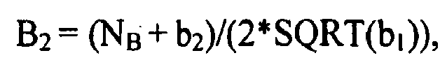
and
- The motor torques TA and TB can be transformed to TX and TY as follows:

wherein TX is the transformation of TA,
TY is the transformation of TB, and
A1, A2, B1, B2 comprise application-specific scalar values. - Eq. 11 can thus be further reduced as follows.


- Eq. 12 specifies the transformation of motor torque TA to TX and the transformation of motor torque TB to TY. Thus, a new coordinate system referred to as TX/TY space is defined, and Eq. 13 comprises battery power, PBAT, transformed into TX/TY space. Therefore, the battery power range between maximum and minimum battery power PBAT_MAX and PBAT_MIN can be calculated and graphed as radii RMax and RMin with a center at locus (0, 0) in the transformed space TX/TY, designated by the letter K as shown with reference to
Fig. 3 , wherein:
and
- The minimum and maximum battery powers, PBAT_MIN and PBAT_MAX, are preferably correlated to battery physics, e.g. state of charge, temperature, voltage and usage (amp-hour/hour). The parameter C, above, is defined as the absolute minimum possible battery power at given motor speeds, NA and NB, within the motor torque limits. Physically, when TA=0 and TB=0 the output power from the first and second
electric machines ESD 74. The positive sign ('+') is defined as discharging power from theESD 74, and the negative sign ('-') is defined as charging power into theESD 74. RMax defines a maximum battery power, typically a discharging power, and RMin defines a maximum battery charging power. - The forgoing transformations to the TX/TY space are shown in
Fig. 3 , with representations of the battery power constraints as concentric circles having radii of RMin and RMax ('Battery Power Constraints') and linear representations of the motor torque constraints ('Motor Torque Constraints') circumscribing an allowable operating region. Analytically, the transformed vector [TX TY] determined in Eq. 12 is solved simultaneously with the vector defined in Eq. 13 comprising the minimum and maximum battery powers identified by RMin and RMax to identify a range of allowable torques in the TX/TY space which are made up of motor torques TA and TB constrained by the minimum and maximum battery powers PBAT_MIN to PBAT_MAX. The range of allowable torques in the TX/TY space is shown with reference toFig. 3 , wherein points A, B, C, D, and E represent the bounds, and lines and radii are defined. - A constant torque line can be defined in the TX/TY space, and depicted in
Fig. 3 ('TM1 = C1'), comprising the limit torque TM1, described in Eq. 1, above. The limit torque TM1 comprises the output torque To in this embodiment, Eqs. 1, 2, and 3 restated in the TX/TY space are as follows.


- Defining TM1_XY, TM2_XY , and TM3_XY as parts of TM1, TM2, and TM3, contributed by TA and TB only, then:


- The following coefficients can be defined:


and
- Thus, Eqs. 1, 2, and 3 are transformed to TX/TY space as follows.


- The speed constraints, motor torque constraints, and battery power constraints can be determined during ongoing operation and expressed in linear equations which are transformed to TX/TY space. Eq. 21 comprises a limit torque function describing the output torque constraint TM1, e.g., To.
- The torque limit of the
transmission 10, in this embodiment the output torque To, can be determined by using Eq. 21 subject to the TM2 and TM3 constraints defined by Eqs. 22 and 23to determine a transformed maximum or minimum limit torque in the TX/TY space, comprising one of TM1_XYMax and TM1_XYMin, e.g., maximum and minimum output torques TO_Max and TO_Min that have been transformed. Subsequently the transformed maximum or minimum limit torque in the TX/TY space can be retransformed out of the TX/TY space to determine maximum or minimum limit torques TM1_Max and TM1_Min for managing control and operation of thetransmission 14 and the first and secondelectric machines - In
Figs. 4 - 9 , motor torque constraints are shown comprising the transformed minimum and maximum motor torques for TA and TB transformed to TX/TY space ('Tx_Min', 'Tx_Max', 'Ty_Min', 'Ty_Max'). Battery power constraints are transformed to the TX/TY space ('R_Min', 'R_Max') and have a center locus point K comprising (Kx, Ky) = (0,0). A first output torque constraint comprising a constant torque line ('Tm1 = C1') representing line TM1_XY has a positive slope of a/b of the general form in Eq. 24:
wherein a < 0, b > 0, and C is a constant term. In the ensuing descriptions, the line TM1_XY has a positive slope of 1:1 for purposes of illustration. An additional constraint line ('Tm2 = C2') representing line TM2_XY is shown.
The additional constraint line TM2_XY comprises the input torque TI in this embodiment. Alternatively, the additional constraint line TM2_XY can comprise the clutch torque or another constraint. -
Fig. 4 graphically shows a first case wherein battery power at the point of the transformed minimum motor torque TA ('Tx_Min') and the transformed maximum motor torque TB ('Ty_Max') is greater than the transformed maximum battery power ('R_Max'). The battery power constraints are less than sufficient to meet a required battery power for achieving the maximum output torque based upon the motor torque constraints. Points L1 and L2 are points on the additional constraint line TM2_XY ('Tm2 = C2') which intersect the transformed motor torques. A second line is generated perpendicular to the additional constraint line TM2_XY and passing through the center locus point K, designated as line L3L4, and intersects the additional constraint line TM2_XY at point Q. Point Q identifies the point on the additional constraint line TM2_XY that minimizes violation of the battery power constraints. Point Q is within the motor torque constraints comprising the transformed minimum and maximum motor torques for TA and TB('Tx_Min', 'Tx_Max', 'Ty_Min', 'Ty_Max'). Point P is a tangent point whereat the output torque constraint TM1 ('Tm1=C1') intersects the battery power constraint comprising the transformed maximum battery power ('R_max'). The preferred solution for this set of constraints is the Point Q which meets the additional constraint TM2_XY and has the least violation of the battery power constraint. The solution set preferably comprises a (Tx, Ty) point representing a preferred solution for controlling operation that can be retransformed to motor torques (TA, TB) to control operation of the first and secondelectric machines -
Fig. 5 graphically shows a second case wherein battery power at the point of the transformed minimum motor torque TA ('Tx_Min') and the transformed maximum motor torque TB ('Ty_Max') is greater than the transformed maximum battery power ('R_Max'). The battery power constraints are less than sufficient to meet a required battery power for achieving the maximum output torque based upon the motor torque constraints. Points L1 and L2 are points on the additional constraint line TM2_XY ('Tm2 = C2') which intersect the transformed motor torques. A second line is generated perpendicular to the additional constraint line TM2_XY and passing through the center locus point K, designated as line L3L4, which intersects the additional constraint line TM2_XY at point Q. Point Q identifies the point on the additional constraint line TM2_XY which minimizes violation of the battery power constraints. Point Q is outside the motor torque constraints comprising the transformed minimum and maximum motor torques for TA and TB('Tx_Min', 'Tx_Max', 'Ty_Min', 'Ty_Max'). Point P is a tangent point whereat the constant line ('Tm1 =C1') intersects the battery power constraint comprising the transformed maximum battery power ('R_max'). The L1L2 line segment represents the limits at which the solution meets the additional constraint line TM2_XY and the motor torque constraints. Point Q is the optimal solution, however, it falls outside the boundaries of the L1L2 line segment. In order to meet the constraints, Point R is set to the L2 point of the L1L2 line segment since it is the closest point in the L1L2 line segment to the optimal solution Q. Thus, the preferred solution for this set of constraints is Point R which meets the TM2 constraint and has the least violation of the battery power constraint. The solution set comprises a (Tx, Ty) point representing the preferred solution Point R for controlling operation that can be retransformed to motor torques (TA, TB) to control operation of the first and secondelectric machines -
Fig. 6 graphically shows a third case wherein battery power at the point of the transformed minimum motor torque TA ('Tx_Min') and the transformed maximum motor torque TB ('Ty_Max') is greater than the transformed maximum battery power ('R_Max'). The battery power constraints are less than sufficient to meet a required battery power for achieving the maximum output torque based upon the motor torque constraints. Points L1 and L2 are points on the additional constraint line TM2_XY ('Tm2 = C2') that intersect the transformed motor torques. A line segment L3L4 is defined as points on the additional constraint line TM2_XY,
wherein points L3 and L4 define intersections of the additional constraint line TM2_XY and the transformed maximum battery power. The additional constraint line TM2_XY intersects the output torque constraint TM1 ('Tm1 =C1') at point Q. Point Q is within the motor torque constraints comprising the transformed minimum and maximum motor torques for TA and TB ('Tx_Min', 'Tx_Max', 'Ty_Min', 'Ty_Max'), but is outside of the battery power constraints. Therefore, the preferred solution for this set of constraints is Point R, which is the point whereat the additional constraint line TM2_XY intersects the transformed maximum battery power ('R_Max'), i.e., Point L3. The solution set consists of the (Tx, Ty) point representing the preferred solution for controlling operation that can be retransformed to motor torques (TA, TB) to control operation of the first and secondelectric machines -
Fig. 7 graphically shows a fourth case wherein battery power at the point of the transformed minimum motor torque TA ('Tx_Min') and the transformed maximum motor torque TB ('Ty_Max') is greater than the transformed maximum battery power ('R_Max'). The battery power constraints are less than sufficient to meet a required battery power for achieving the maximum output torque based upon the motor torque constraints. Points L1 and L2 are points on the additional constraint line TM2_XY ('Tm2 = C2') that intersect the transformed motor torques. A line segment L3L4 is defined as points on the additional constraint line TM2_XY,
wherein points L3 and L4 define intersections of the additional constraint line TM2_XY and the transformed maximum battery power. There is some overlap between line segment L3L4 and line segment L1L2. The additional constraint line TM2_XY intersects the output torque constraint TM1 ('Tm1 =C1') at point Q. Point Q is within the motor torque constraints comprising the transformed minimum and maximum motor torques for TA and TB ('Tx_Min', 'Tx_Max', 'Ty_Min', 'Ty_Max'), but is outside the battery power constraints. The L3L2 line segment represents the limits at which the solution meets TM2 and the motor torque constraints. Point Q is the optimal solution, however, it falls outside the boundaries of the L3L2 line segment. In order to meet the constraints, Point R is set equal to the L3 point of the line segment since it is the closest point in the segment to the optimal solution Q. The preferred solution for this set of constraints is the Point R that meets the additional constraint line TM2_XY and maximizes the output torque. The solution set consists of the (Tx, Ty) point representing the preferred solution for controlling operation that can be retransformed to motor torques (TA, TB) to control operation of the first and secondelectric machines -
Fig. 8 graphically shows a fifth case wherein battery power at the point of the transformed minimum motor torque TA ('Tx_Min') and the transformed maximum motor torque TB ('Ty_Max') is greater than the transformed maximum battery power ('R_Max'). The battery power constraints are less than sufficient to meet a required battery power for achieving the maximum output torque based upon the motor torque constraints. Points L1 and L2 are points on the additional constraint line TM2_XY ('Tm2 = C2') that intersect the transformed motor torques. A line segment L3L4 is defined as points on the additional constraint line TM2_XY, wherein points L3 and L4 define intersections of the additional constraint line TM2_XY and the transformed maximum battery power. There is no overlap between line segment L3L4 and line segment L1L2. The additional constraint line TM2_XY intersects the output torque constraint TM1 ('Tm1=C1') at point Q. Point Q is outside the motor torque constraints comprising the transformed minimum and maximum motor torques for TA and TB ('Tx_Min', 'Tx_Max', 'Ty_Min', 'Ty_Max'), but is within the battery power constraints. Point P defines a maximum point whereat the battery power constraints intersect the motor torque constraints, but does not satisfy the additional constraint line TM2_XY. Point R is set equal to the L2 point of the line segment since it is the closest point in the segment to the optimal solution Q. The preferred solution for this set of constraints is Point R that satisfies the motor torque constraints and the additional constraint line TM2_XY and has the least violation of the battery power constraints. The solution set consists of the (Tx, Ty) point representing the preferred solution for controlling operation that can be retransformed to motor torques (TA, TB) to control operation of the first and secondelectric machines -
Fig. 9 graphically shows a sixth case wherein the additional constraint line TM2_XY ('Tm2 = C2') intersects the transformed maximum battery power ('R_Max') at points having Tx coordinates of X4 and X1, and intersects the transformed minimum battery power ('R_Min') at points having Tx coordinates of X3 and X2. Furthermore, the additional constraint line TM2_XY intersects the transformed minimum motor torque TA ('Tx_Min') at a point having a Tx coordinate of XS and intersects the transformed maximum motor torque TA ('Tx_Max') at a point having a Tx coordinate of XL. A first line segment X3X4 is defined as existing between X3 and X4; a second line segment X1X2 is defined as existing between X1 and X2; a third line segment XLXS is defined as existing between points XL and XS; and a fourth line segment X2XL is defined as existing between points X2 and XL. The first output torque constraint ('Tm1') is not depicted. When the first output torque constraint intersects with one of the first line segment X3X4 and the fourth line segment X2XL, the preferred solution is the point on the additional constraint line TM2_XY whereat the first output torque constraint intersects the line segment (not shown). When the first output torque constraint does not intersect with either the first line segment X3X4 or the fourth line segment X2XL, the preferred solution is the one of points X4, X3, X2 and XL that is closest in proximity to the first output torque constraint (not shown). A (Tx, Ty) coordinate represents the preferred solution for controlling operation that can be retransformed to motor torques (TA, TB) to control operation of the first and secondelectric machines - The embodiment described hereinabove is based upon the line TM1_XY having a positive slope of a/b of the general form in Eq. 24 (as above):

wherein a < 0, b > 0, and C is a constant term, with a slope of a/b = 1:1 for purposes of illustration with the x-intercept C being changeable. The description is applicable to combinations of a > 0, b < 0, and the slope of a/b being less than 1:1 and being greater than 1:1. - It is understood that modifications are allowable within the scope of the disclosure. The disclosure has been described with specific reference to the preferred embodiments and modifications thereto. Further modifications and alterations may occur to others upon reading and understanding the specification. It is intended to include all such modifications and alterations insofar as they come within the scope of the appended claims.
Claims (14)
- A method for controlling an electro-mechanical transmission (10) operatively coupled to first and second electric machines (56, 72) to transmit power to an output member (64), the method comprising:determining motor torque constraints for the first and second electric machines (56, 72);determining battery power constraints for an electrical energy storage device (74) electrically connected to the first and second electric machines (56, 72);determining an additional constraint on the electro-mechanical transmission (10);controlling operation of the electro-mechanical transmission (10) and the
first and second electric machines (56, 72) based upon the motor torque constraints, the additional constraint, and the battery power constraints;characterized bydetermining a preferred output torque to the output member (64) of the electro-mechanical transmission (10) that is achievable within the motor torque constraints and is based upon the additional constraint and the battery power constraints when battery power constraints are less than sufficient to meet a required battery power for achieving a maximum output torque based upon the motor torque constraints; andcontrolling operation of the electro-mechanical transmission (10) and the first and second electric machines (56, 72) to achieve the preferred output torque at the output member (64) based upon the motor torque constraints, the additional constraint, and the battery power constraints. - The method of claim 1, wherein the preferred output torque comprises a commanded output torque to the output member (64) to achieve an operator torque request.
- The method of claim 2, further comprising determining a preferred output torque to the output member (64) of the electro-mechanical transmission (10) that is achievable within the additional constraint and that minimizes a violation of a maximum battery power constraint when the additional constraint is achievable within the motor torque constraints and the additional constraint exceeds the maximum battery power constraint.
- The method of claim 2, further comprising determining a preferred output torque to the output member (64) of the electro-mechanical transmission (10) that is achievable within the additional constraint and is constrained by a maximum battery power constraint when the additional constraint is achievable within the motor torque constraints and the additional constraint is achievable within the maximum battery power constraint.
- The method of claim 4, further comprising limiting the preferred output torque to the output member (64) of the electro-mechanical transmission (10) to an output torque achievable within the motor torque constraints and achievable within the maximum battery power constraint.
- The method of claim 2, further comprising determining a preferred output torque to the output member (64) of the electro-mechanical transmission (10) that is achievable within the additional constraint and achievable within the battery power constraints when the additional constraint is achievable within the motor torque constraints and the additional constraint can exceed one of the maximum battery power constraint and the minimum battery power constraint.
- The method of claim 6, wherein the maximum battery power constraint comprises a maximum battery discharging power.
- The method of claim 7, wherein the minimum battery power constraint comprises a minimum battery charging power.
- The method of claim 1, further comprising determining a preferred output torque to the output member (64) of the electro-mechanical transmission (10) that is within the motor torque constraints and is based upon the additional constraint and the battery power constraints.
- The method of claim 1, wherein the additional constraint comprises an input torque to an input shaft (12) from an internal combustion engine (14).
- The method of claim 1, wherein the additional constraint comprises reactive torque across an applied torque transfer clutch in the transmission (10).
- The method of claim 1, further comprising:formulating mathematical equations representing maximum and minimum motor torque constraints for the first and second electric machines (56, 72) and representing maximum and minimum battery power constraints;formulating a mathematical equation representing the output torque;formulating a mathematical equation representing the additional constraint;transforming the mathematical equations representing the maximum and minimum battery power constraints to equations of concentric circles having respective radii;transforming the mathematical equations representing the maximum and minimum motor torque constraints for the first and second electric machines (56, 72) to equations comprising lines;transforming the mathematical equation representing the additional constraint to an equation comprising a line; andtransforming the mathematical equation representing the output torque to an equation comprising a line.
- The method of claim 12, further comprising:determining at least one transformed achievable output torque based upon
the transformed motor torque constraints for the first and second electric machines and the transformed battery power constraints and the transformed additional constraint;determining a transformed achievable maximum output torque from the
electro-mechanical transmission (10); andretransforming the transformed achievable maximum output torque to determine the preferred output torques for the first and second electric machines (56, 72). - The method of claim 12, comprising calculating at least one intersection of the transformed mathematical equations representing the maximum and minimum battery power constraints, the transformed mathematical equations representing the maximum and minimum motor torque constraints for the first and second electric machines (56, 72), the transformed mathematical equation representing the additional constraint, and the transformed mathematical equation representing the output torque.
Applications Claiming Priority (2)
| Application Number | Priority Date | Filing Date | Title |
|---|---|---|---|
| US98482607P | 2007-11-02 | 2007-11-02 | |
| US12/239,760 US8133151B2 (en) | 2007-11-02 | 2008-09-27 | System constraints method of controlling operation of an electro-mechanical transmission with an additional constraint |
Publications (3)
| Publication Number | Publication Date |
|---|---|
| EP2055564A2 EP2055564A2 (en) | 2009-05-06 |
| EP2055564A3 EP2055564A3 (en) | 2010-12-15 |
| EP2055564B1 true EP2055564B1 (en) | 2013-11-27 |
Family
ID=40409854
Family Applications (1)
| Application Number | Title | Priority Date | Filing Date |
|---|---|---|---|
| EP08019028.3A Active EP2055564B1 (en) | 2007-11-02 | 2008-10-30 | System constraints method of controlling operation of an electro-mechanical transmission with an additional constraint |
Country Status (3)
| Country | Link |
|---|---|
| US (1) | US8133151B2 (en) |
| EP (1) | EP2055564B1 (en) |
| CN (1) | CN101480950B (en) |
Families Citing this family (124)
| Publication number | Priority date | Publication date | Assignee | Title |
|---|---|---|---|---|
| US8390240B2 (en) * | 2007-08-06 | 2013-03-05 | GM Global Technology Operations LLC | Absolute position sensor for field-oriented control of an induction motor |
| US7867135B2 (en) | 2007-09-26 | 2011-01-11 | GM Global Technology Operations LLC | Electro-mechanical transmission control system |
| US8234048B2 (en) * | 2007-10-19 | 2012-07-31 | GM Global Technology Operations LLC | Method and system for inhibiting operation in a commanded operating range state for a transmission of a powertrain system |
| US8060267B2 (en) * | 2007-10-23 | 2011-11-15 | GM Global Technology Operations LLC | Method for controlling power flow within a powertrain system |
| US9140337B2 (en) * | 2007-10-23 | 2015-09-22 | GM Global Technology Operations LLC | Method for model based clutch control and torque estimation |
| US8265821B2 (en) * | 2007-10-25 | 2012-09-11 | GM Global Technology Operations LLC | Method for determining a voltage level across an electric circuit of a powertrain |
| US8335623B2 (en) * | 2007-10-25 | 2012-12-18 | GM Global Technology Operations LLC | Method and apparatus for remediation of and recovery from a clutch slip event in a hybrid powertrain system |
| US8187145B2 (en) * | 2007-10-25 | 2012-05-29 | GM Global Technology Operations LLC | Method and apparatus for clutch torque control in mode and fixed gear for a hybrid powertrain system |
| US8296027B2 (en) | 2007-10-25 | 2012-10-23 | GM Global Technology Operations LLC | Method and apparatus to control off-going clutch torque during torque phase for a hybrid powertrain system |
| US8118122B2 (en) * | 2007-10-25 | 2012-02-21 | GM Global Technology Operations LLC | Method and system for monitoring signal integrity in a distributed controls system |
| US8406945B2 (en) * | 2007-10-26 | 2013-03-26 | GM Global Technology Operations LLC | Method and apparatus to control logic valves for hydraulic flow control in an electro-mechanical transmission |
| US8548703B2 (en) | 2007-10-26 | 2013-10-01 | GM Global Technology Operations LLC | Method and apparatus to determine clutch slippage in an electro-mechanical transmission |
| US8167773B2 (en) | 2007-10-26 | 2012-05-01 | GM Global Technology Operations LLC | Method and apparatus to control motor cooling in an electro-mechanical transmission |
| US7985154B2 (en) * | 2007-10-26 | 2011-07-26 | GM Global Technology Operations LLC | Method and apparatus to control hydraulic pressure for component lubrication in an electro-mechanical transmission |
| US8303463B2 (en) * | 2007-10-26 | 2012-11-06 | GM Global Technology Operations LLC | Method and apparatus to control clutch fill pressure in an electro-mechanical transmission |
| US8560191B2 (en) | 2007-10-26 | 2013-10-15 | GM Global Technology Operations LLC | Method and apparatus to control clutch pressures in an electro-mechanical transmission |
| US8204702B2 (en) * | 2007-10-26 | 2012-06-19 | GM Global Technology Operations LLC | Method for estimating battery life in a hybrid powertrain |
| US9097337B2 (en) | 2007-10-26 | 2015-08-04 | GM Global Technology Operations LLC | Method and apparatus to control hydraulic line pressure in an electro-mechanical transmission |
| US8244426B2 (en) * | 2007-10-27 | 2012-08-14 | GM Global Technology Operations LLC | Method and apparatus for monitoring processor integrity in a distributed control module system for a powertrain system |
| US8099219B2 (en) | 2007-10-27 | 2012-01-17 | GM Global Technology Operations LLC | Method and apparatus for securing an operating range state mechanical transmission |
| US8428816B2 (en) * | 2007-10-27 | 2013-04-23 | GM Global Technology Operations LLC | Method and apparatus for monitoring software and signal integrity in a distributed control module system for a powertrain system |
| US8062174B2 (en) * | 2007-10-27 | 2011-11-22 | GM Global Technology Operations LLC | Method and apparatus to control clutch stroke volume in an electro-mechanical transmission |
| US8112194B2 (en) * | 2007-10-29 | 2012-02-07 | GM Global Technology Operations LLC | Method and apparatus for monitoring regenerative operation in a hybrid powertrain system |
| US8290681B2 (en) * | 2007-10-29 | 2012-10-16 | GM Global Technology Operations LLC | Method and apparatus to produce a smooth input speed profile in mode for a hybrid powertrain system |
| US8489293B2 (en) * | 2007-10-29 | 2013-07-16 | GM Global Technology Operations LLC | Method and apparatus to control input speed profile during inertia speed phase for a hybrid powertrain system |
| US8170762B2 (en) | 2007-10-29 | 2012-05-01 | GM Global Technology Operations LLC | Method and apparatus to control operation of a hydraulic pump for an electro-mechanical transmission |
| US8282526B2 (en) * | 2007-10-29 | 2012-10-09 | GM Global Technology Operations LLC | Method and apparatus to create a pseudo torque phase during oncoming clutch engagement to prevent clutch slip for a hybrid powertrain system |
| US8209098B2 (en) * | 2007-10-29 | 2012-06-26 | GM Global Technology Operations LLC | Method and apparatus for monitoring a transmission range selector in a hybrid powertrain transmission |
| US8095254B2 (en) * | 2007-10-29 | 2012-01-10 | GM Global Technology Operations LLC | Method for determining a power constraint for controlling a powertrain system |
| US8073602B2 (en) * | 2007-11-01 | 2011-12-06 | GM Global Technology Operations LLC | System constraints method of controlling operation of an electro-mechanical transmission with an additional constraint range |
| US8145375B2 (en) * | 2007-11-01 | 2012-03-27 | GM Global Technology Operations LLC | System constraints method of determining minimum and maximum torque limits for an electro-mechanical powertrain system |
| US7977896B2 (en) | 2007-11-01 | 2011-07-12 | GM Global Technology Operations LLC | Method of determining torque limit with motor torque and battery power constraints |
| US8556011B2 (en) * | 2007-11-01 | 2013-10-15 | GM Global Technology Operations LLC | Prediction strategy for thermal management and protection of power electronic hardware |
| US8035324B2 (en) * | 2007-11-01 | 2011-10-11 | GM Global Technology Operations LLC | Method for determining an achievable torque operating region for a transmission |
| US8131437B2 (en) * | 2007-11-02 | 2012-03-06 | GM Global Technology Operations LLC | Method for operating a powertrain system to transition between engine states |
| US8121767B2 (en) * | 2007-11-02 | 2012-02-21 | GM Global Technology Operations LLC | Predicted and immediate output torque control architecture for a hybrid powertrain system |
| US8200403B2 (en) | 2007-11-02 | 2012-06-12 | GM Global Technology Operations LLC | Method for controlling input torque provided to a transmission |
| US8585540B2 (en) | 2007-11-02 | 2013-11-19 | GM Global Technology Operations LLC | Control system for engine torque management for a hybrid powertrain system |
| US8287426B2 (en) * | 2007-11-02 | 2012-10-16 | GM Global Technology Operations LLC | Method for controlling voltage within a powertrain system |
| US8170764B2 (en) | 2007-11-02 | 2012-05-01 | GM Global Technology Operations LLC | Method and apparatus to reprofile input speed during speed during speed phase during constrained conditions for a hybrid powertrain system |
| US8121765B2 (en) * | 2007-11-02 | 2012-02-21 | GM Global Technology Operations LLC | System constraints method of controlling operation of an electro-mechanical transmission with two external input torque ranges |
| US8847426B2 (en) | 2007-11-02 | 2014-09-30 | GM Global Technology Operations LLC | Method for managing electric power in a powertrain system |
| US8825320B2 (en) * | 2007-11-02 | 2014-09-02 | GM Global Technology Operations LLC | Method and apparatus for developing a deceleration-based synchronous shift schedule |
| US8224539B2 (en) | 2007-11-02 | 2012-07-17 | GM Global Technology Operations LLC | Method for altitude-compensated transmission shift scheduling |
| US8002667B2 (en) * | 2007-11-03 | 2011-08-23 | GM Global Technology Operations LLC | Method for determining input speed acceleration limits in a hybrid transmission |
| US8296021B2 (en) | 2007-11-03 | 2012-10-23 | GM Global Technology Operations LLC | Method for determining constraints on input torque in a hybrid transmission |
| US8155814B2 (en) | 2007-11-03 | 2012-04-10 | GM Global Technology Operations LLC | Method of operating a vehicle utilizing regenerative braking |
| US8010247B2 (en) | 2007-11-03 | 2011-08-30 | GM Global Technology Operations LLC | Method for operating an engine in a hybrid powertrain system |
| US8204664B2 (en) | 2007-11-03 | 2012-06-19 | GM Global Technology Operations LLC | Method for controlling regenerative braking in a vehicle |
| US8285431B2 (en) | 2007-11-03 | 2012-10-09 | GM Global Technology Operations LLC | Optimal selection of hybrid range state and/or input speed with a blended braking system in a hybrid electric vehicle |
| US8135526B2 (en) * | 2007-11-03 | 2012-03-13 | GM Global Technology Operations LLC | Method for controlling regenerative braking and friction braking |
| US8068966B2 (en) | 2007-11-03 | 2011-11-29 | GM Global Technology Operations LLC | Method for monitoring an auxiliary pump for a hybrid powertrain |
| US8224514B2 (en) * | 2007-11-03 | 2012-07-17 | GM Global Technology Operations LLC | Creation and depletion of short term power capability in a hybrid electric vehicle |
| US8406970B2 (en) | 2007-11-03 | 2013-03-26 | GM Global Technology Operations LLC | Method for stabilization of optimal input speed in mode for a hybrid powertrain system |
| US8260511B2 (en) * | 2007-11-03 | 2012-09-04 | GM Global Technology Operations LLC | Method for stabilization of mode and fixed gear for a hybrid powertrain system |
| US8868252B2 (en) * | 2007-11-03 | 2014-10-21 | GM Global Technology Operations LLC | Control architecture and method for two-dimensional optimization of input speed and input power including search windowing |
| US8630776B2 (en) * | 2007-11-04 | 2014-01-14 | GM Global Technology Operations LLC | Method for controlling an engine of a hybrid powertrain in a fuel enrichment mode |
| US8098041B2 (en) | 2007-11-04 | 2012-01-17 | GM Global Technology Operations LLC | Method of charging a powertrain |
| US8118903B2 (en) | 2007-11-04 | 2012-02-21 | GM Global Technology Operations LLC | Method for preferential selection of modes and gear with inertia effects for a hybrid powertrain system |
| US8126624B2 (en) | 2007-11-04 | 2012-02-28 | GM Global Technology Operations LLC | Method for selection of optimal mode and gear and input speed for preselect or tap up/down operation |
| US8214093B2 (en) * | 2007-11-04 | 2012-07-03 | GM Global Technology Operations LLC | Method and apparatus to prioritize transmission output torque and input acceleration for a hybrid powertrain system |
| US8374758B2 (en) * | 2007-11-04 | 2013-02-12 | GM Global Technology Operations LLC | Method for developing a trip cost structure to understand input speed trip for a hybrid powertrain system |
| US8112206B2 (en) | 2007-11-04 | 2012-02-07 | GM Global Technology Operations LLC | Method for controlling a powertrain system based upon energy storage device temperature |
| US8204656B2 (en) | 2007-11-04 | 2012-06-19 | GM Global Technology Operations LLC | Control architecture for output torque shaping and motor torque determination for a hybrid powertrain system |
| US8002665B2 (en) * | 2007-11-04 | 2011-08-23 | GM Global Technology Operations LLC | Method for controlling power actuators in a hybrid powertrain system |
| US8414449B2 (en) * | 2007-11-04 | 2013-04-09 | GM Global Technology Operations LLC | Method and apparatus to perform asynchronous shifts with oncoming slipping clutch torque for a hybrid powertrain system |
| US8594867B2 (en) * | 2007-11-04 | 2013-11-26 | GM Global Technology Operations LLC | System architecture for a blended braking system in a hybrid powertrain system |
| US8145397B2 (en) * | 2007-11-04 | 2012-03-27 | GM Global Technology Operations LLC | Optimal selection of blended braking capacity for a hybrid electric vehicle |
| US8494732B2 (en) * | 2007-11-04 | 2013-07-23 | GM Global Technology Operations LLC | Method for determining a preferred engine operation in a hybrid powertrain system during blended braking |
| US8214120B2 (en) * | 2007-11-04 | 2012-07-03 | GM Global Technology Operations LLC | Method to manage a high voltage system in a hybrid powertrain system |
| US8200383B2 (en) | 2007-11-04 | 2012-06-12 | GM Global Technology Operations LLC | Method for controlling a powertrain system based upon torque machine temperature |
| US8221285B2 (en) * | 2007-11-04 | 2012-07-17 | GM Global Technology Operations LLC | Method and apparatus to offload offgoing clutch torque with asynchronous oncoming clutch torque, engine and motor torque for a hybrid powertrain system |
| US8092339B2 (en) * | 2007-11-04 | 2012-01-10 | GM Global Technology Operations LLC | Method and apparatus to prioritize input acceleration and clutch synchronization performance in neutral for a hybrid powertrain system |
| US8000866B2 (en) | 2007-11-04 | 2011-08-16 | GM Global Technology Operations LLC | Engine control system for torque management in a hybrid powertrain system |
| US8346449B2 (en) * | 2007-11-04 | 2013-01-01 | GM Global Technology Operations LLC | Method and apparatus to provide necessary output torque reserve by selection of hybrid range state and input speed for a hybrid powertrain system |
| US7988594B2 (en) | 2007-11-04 | 2011-08-02 | GM Global Technology Operations LLC | Method for load-based stabilization of mode and fixed gear operation of a hybrid powertrain system |
| US8095282B2 (en) | 2007-11-04 | 2012-01-10 | GM Global Technology Operations LLC | Method and apparatus for soft costing input speed and output speed in mode and fixed gear as function of system temperatures for cold and hot operation for a hybrid powertrain system |
| US8214114B2 (en) | 2007-11-04 | 2012-07-03 | GM Global Technology Operations LLC | Control of engine torque for traction and stability control events for a hybrid powertrain system |
| US8135532B2 (en) * | 2007-11-04 | 2012-03-13 | GM Global Technology Operations LLC | Method for controlling output power of an energy storage device in a powertrain system |
| US8248023B2 (en) * | 2007-11-04 | 2012-08-21 | GM Global Technology Operations LLC | Method of externally charging a powertrain |
| US8121766B2 (en) * | 2007-11-04 | 2012-02-21 | GM Global Technology Operations LLC | Method for operating an internal combustion engine to transmit power to a driveline |
| US8138703B2 (en) * | 2007-11-04 | 2012-03-20 | GM Global Technology Operations LLC | Method and apparatus for constraining output torque in a hybrid powertrain system |
| US8067908B2 (en) * | 2007-11-04 | 2011-11-29 | GM Global Technology Operations LLC | Method for electric power boosting in a powertrain system |
| US8818660B2 (en) * | 2007-11-04 | 2014-08-26 | GM Global Technology Operations LLC | Method for managing lash in a driveline |
| US8112192B2 (en) * | 2007-11-04 | 2012-02-07 | GM Global Technology Operations LLC | Method for managing electric power within a powertrain system |
| US8504259B2 (en) | 2007-11-04 | 2013-08-06 | GM Global Technology Operations LLC | Method for determining inertia effects for a hybrid powertrain system |
| US8079933B2 (en) | 2007-11-04 | 2011-12-20 | GM Global Technology Operations LLC | Method and apparatus to control engine torque to peak main pressure for a hybrid powertrain system |
| US9008926B2 (en) | 2007-11-04 | 2015-04-14 | GM Global Technology Operations LLC | Control of engine torque during upshift and downshift torque phase for a hybrid powertrain system |
| US8396634B2 (en) * | 2007-11-04 | 2013-03-12 | GM Global Technology Operations LLC | Method and apparatus for maximum and minimum output torque performance by selection of hybrid range state and input speed for a hybrid powertrain system |
| US8897975B2 (en) * | 2007-11-04 | 2014-11-25 | GM Global Technology Operations LLC | Method for controlling a powertrain system based on penalty costs |
| US8121768B2 (en) * | 2007-11-05 | 2012-02-21 | GM Global Technology Operations LLC | Method for controlling a hybrid powertrain system based upon hydraulic pressure and clutch reactive torque capacity |
| US8448731B2 (en) | 2007-11-05 | 2013-05-28 | GM Global Technology Operations LLC | Method and apparatus for determination of fast actuating engine torque for a hybrid powertrain system |
| US8099204B2 (en) | 2007-11-05 | 2012-01-17 | GM Global Technology Operatons LLC | Method for controlling electric boost in a hybrid powertrain |
| US8160761B2 (en) * | 2007-11-05 | 2012-04-17 | GM Global Technology Operations LLC | Method for predicting an operator torque request of a hybrid powertrain system |
| US8249766B2 (en) * | 2007-11-05 | 2012-08-21 | GM Global Technology Operations LLC | Method of determining output torque limits of a hybrid transmission operating in a fixed gear operating range state |
| US8219303B2 (en) | 2007-11-05 | 2012-07-10 | GM Global Technology Operations LLC | Method for operating an internal combustion engine for a hybrid powertrain system |
| US8073601B2 (en) * | 2007-11-05 | 2011-12-06 | GM Global Technology Operations LLC | Method for preferential selection of mode and gear and input speed based on multiple engine state fueling costs for a hybrid powertrain system |
| US8229633B2 (en) | 2007-11-05 | 2012-07-24 | GM Global Technology Operations LLC | Method for operating a powertrain system to control engine stabilization |
| US8070647B2 (en) | 2007-11-05 | 2011-12-06 | GM Global Technology Operations LLC | Method and apparatus for adapting engine operation in a hybrid powertrain system for active driveline damping |
| US8112207B2 (en) | 2007-11-05 | 2012-02-07 | GM Global Technology Operations LLC | Method and apparatus to determine a preferred output torque for operating a hybrid transmission in a continuously variable mode |
| US8285432B2 (en) * | 2007-11-05 | 2012-10-09 | GM Global Technology Operations LLC | Method and apparatus for developing a control architecture for coordinating shift execution and engine torque control |
| US8135519B2 (en) * | 2007-11-05 | 2012-03-13 | GM Global Technology Operations LLC | Method and apparatus to determine a preferred output torque for operating a hybrid transmission in a fixed gear operating range state |
| US8165777B2 (en) | 2007-11-05 | 2012-04-24 | GM Global Technology Operations LLC | Method to compensate for transmission spin loss for a hybrid powertrain system |
| US8155815B2 (en) * | 2007-11-05 | 2012-04-10 | Gm Global Technology Operation Llc | Method and apparatus for securing output torque in a distributed control module system for a powertrain system |
| US8321100B2 (en) * | 2007-11-05 | 2012-11-27 | GM Global Technology Operations LLC | Method and apparatus for dynamic output torque limiting for a hybrid powertrain system |
| US8285462B2 (en) * | 2007-11-05 | 2012-10-09 | GM Global Technology Operations LLC | Method and apparatus to determine a preferred output torque in mode and fixed gear operation with clutch torque constraints for a hybrid powertrain system |
| US8281885B2 (en) | 2007-11-06 | 2012-10-09 | GM Global Technology Operations LLC | Method and apparatus to monitor rotational speeds in an electro-mechanical transmission |
| US8179127B2 (en) * | 2007-11-06 | 2012-05-15 | GM Global Technology Operations LLC | Method and apparatus to monitor position of a rotatable shaft |
| US8209097B2 (en) * | 2007-11-07 | 2012-06-26 | GM Global Technology Operations LLC | Method and control architecture to determine motor torque split in fixed gear operation for a hybrid powertrain system |
| US8195349B2 (en) * | 2007-11-07 | 2012-06-05 | GM Global Technology Operations LLC | Method for predicting a speed output of a hybrid powertrain system |
| US8433486B2 (en) * | 2007-11-07 | 2013-04-30 | GM Global Technology Operations LLC | Method and apparatus to determine a preferred operating point for an engine of a powertrain system using an iterative search |
| US8073610B2 (en) | 2007-11-07 | 2011-12-06 | GM Global Technology Operations LLC | Method and apparatus to control warm-up of an exhaust aftertreatment system for a hybrid powertrain |
| US8267837B2 (en) | 2007-11-07 | 2012-09-18 | GM Global Technology Operations LLC | Method and apparatus to control engine temperature for a hybrid powertrain |
| US8277363B2 (en) | 2007-11-07 | 2012-10-02 | GM Global Technology Operations LLC | Method and apparatus to control temperature of an exhaust aftertreatment system for a hybrid powertrain |
| US8271173B2 (en) | 2007-11-07 | 2012-09-18 | GM Global Technology Operations LLC | Method and apparatus for controlling a hybrid powertrain system |
| US8126604B2 (en) * | 2009-11-30 | 2012-02-28 | GM Global Technology Operations LLC | Method of determining output torque constraints for a powertrain |
| US8706346B2 (en) * | 2010-11-01 | 2014-04-22 | GM Global Technology Operations LLC | Robust motor torque performance diagnostics algorithm for electric drive systems in hybrid vehicles |
| US8583306B2 (en) * | 2011-06-03 | 2013-11-12 | GM Global Technology Operations LLC | Method for controlling torque output of a hybrid powertrain system |
| US8827865B2 (en) | 2011-08-31 | 2014-09-09 | GM Global Technology Operations LLC | Control system for a hybrid powertrain system |
| US8801567B2 (en) | 2012-02-17 | 2014-08-12 | GM Global Technology Operations LLC | Method and apparatus for executing an asynchronous clutch-to-clutch shift in a hybrid transmission |
| US9067598B2 (en) * | 2012-06-14 | 2015-06-30 | GM Global Technology Operations LLC | Method and apparatus for controlling a high-voltage electrical system for a multi-mode transmission |
| US8989940B1 (en) * | 2013-09-19 | 2015-03-24 | GM Global Technology Operations LLC | Method and apparatus for controlling a multi-mode powertrain system |
| CN111204323B (en) * | 2018-11-22 | 2023-03-28 | 丰田自动车株式会社 | Power transmission system |
| CN113858934A (en) * | 2020-06-30 | 2021-12-31 | 中车时代电动汽车股份有限公司 | Hybrid power system and vehicle adopting same |
Family Cites Families (207)
| Publication number | Priority date | Publication date | Assignee | Title |
|---|---|---|---|---|
| JP3000943B2 (en) * | 1996-07-02 | 2000-01-17 | トヨタ自動車株式会社 | Power output device and control method thereof |
| US6300735B1 (en) | 2000-03-22 | 2001-10-09 | Caterpillar Inc. | Control for a two degree of freedom electromechanical transmission and associated method |
| JP3933106B2 (en) | 2003-07-30 | 2007-06-20 | トヨタ自動車株式会社 | POWER OUTPUT DEVICE, ITS CONTROL METHOD, AND AUTOMOBILE |
| US6832148B1 (en) | 2003-10-14 | 2004-12-14 | General Motors Corporation | Automatic engine stop and restart mode for reducing emissions of a hybrid electric vehicle |
| US7356398B2 (en) * | 2003-10-14 | 2008-04-08 | General Motors Corporation | Synchronous shift control in an electrically variable transmission |
| US6957137B2 (en) * | 2003-10-14 | 2005-10-18 | General Motors Corporation | Real-time operating parameter selection in a vehicular transmission |
| US7110871B2 (en) * | 2003-10-14 | 2006-09-19 | General Motors Corporation | Method for determining preferred input operating points for a vehicle transmission |
| US6868318B1 (en) * | 2003-10-14 | 2005-03-15 | General Motors Corporation | Method for adjusting battery power limits in a hybrid electric vehicle to provide consistent launch characteristics |
| US6910493B2 (en) * | 2003-10-14 | 2005-06-28 | General Motors Corporation | Control apparatus, method and diagnostic for hydraulic fill and drain |
| US7130734B2 (en) * | 2003-10-14 | 2006-10-31 | General Motors Corporation | Two clutch fixed-ratio exit control for multi-mode hybrid drive |
| US7110869B2 (en) * | 2003-10-14 | 2006-09-19 | General Motors Corporation | Hybrid transmission member speed determination, sensor diagnostics and fault recovery |
| US7219000B2 (en) * | 2003-10-14 | 2007-05-15 | General Motors Corporation | Speed control for an electrically variable transmission |
| US7127337B2 (en) * | 2003-10-14 | 2006-10-24 | General Motors Corporation | Silent operating mode for reducing emissions of a hybrid electric vehicle |
| US6946818B2 (en) * | 2003-10-14 | 2005-09-20 | General Motors Corporation | Method of determining battery power limits for an energy storage system of a hybrid electric vehicle |
| US7200476B2 (en) * | 2003-10-14 | 2007-04-03 | General Motors Corporation | Optimal selection of input torque considering battery utilization for a hybrid electric vehicle |
| US7449891B2 (en) * | 2003-10-14 | 2008-11-11 | General Motors Corporation | Managing service life of a battery |
| JP3991975B2 (en) * | 2003-11-12 | 2007-10-17 | 日産自動車株式会社 | Shift control device for hybrid transmission |
| US7301304B2 (en) | 2004-02-14 | 2007-11-27 | General Motors Corporation | Energy storage system state of charge diagnostic |
| US7010406B2 (en) | 2004-02-14 | 2006-03-07 | General Motors Corporation | Shift inhibit control for multi-mode hybrid drive |
| US7222013B2 (en) | 2004-02-14 | 2007-05-22 | General Motors Corporation | Throttle phase out control |
| US7324885B2 (en) | 2004-02-14 | 2008-01-29 | General Motors Corporation | Shift through neutral control in an electrically variable transmission |
| US7076356B2 (en) | 2004-02-14 | 2006-07-11 | General Motors Corporation | Optimal selection of input torque with stability of power flow for a hybrid electric vehicle |
| US6976388B2 (en) | 2004-05-14 | 2005-12-20 | General Motors Corporation | Diagnostic method for a torque control of an electrically variable transmission |
| US7163487B2 (en) | 2004-05-14 | 2007-01-16 | General Motors Corporation | Engine retard operation scheduling and management in a hybrid vehicle |
| US7587442B2 (en) | 2004-05-14 | 2009-09-08 | Gm Global Technology Operations, Inc. | Method of determining the derivative of an input signal |
| US7222014B2 (en) | 2004-05-14 | 2007-05-22 | General Motors Corporation | Method for automatic traction control in a hybrid electric vehicle |
| US7160224B2 (en) | 2004-05-14 | 2007-01-09 | General Motors Corporation | Single motor recovery for an electrically variable transmission |
| US7028657B2 (en) | 2004-05-14 | 2006-04-18 | General Motors Corporation | Multi-stage compression ignition engine start |
| US7217221B2 (en) | 2004-05-14 | 2007-05-15 | General Motors Corporation | Method for active engine stop of a hybrid electric vehicle |
| US7131708B2 (en) | 2004-05-14 | 2006-11-07 | General Motors Corporation | Coordinated regenerative and engine retard braking for a hybrid vehicle |
| US7277781B2 (en) | 2004-05-14 | 2007-10-02 | General Motors Corporation | Method of undervoltage protection during engine cranking |
| US7214165B2 (en) | 2004-05-14 | 2007-05-08 | General Motors Corporation | Method of automatically flushing debris from an electrically-operated hydraulic valve |
| US7369930B2 (en) | 2004-05-14 | 2008-05-06 | General Motors Corporation | Method and apparatus to control hydraulic pressure in an electrically variable transmission |
| US7653474B2 (en) | 2004-05-14 | 2010-01-26 | Gm Global Technology Operations, Inc. | Method of determining engine output power in a hybrid electric vehicle |
| US7368886B2 (en) | 2004-05-14 | 2008-05-06 | General Motors Corporation | Method of testing motor torque integrity in a hybrid electric vehicle |
| US7236871B2 (en) | 2004-05-14 | 2007-06-26 | General Motors Corporation | Acceleration limiting for a vehicle |
| US7305873B2 (en) | 2004-05-15 | 2007-12-11 | General Motors Corporation | Method for dynamically determining peak output torque in an electrically variable transmission |
| US7103463B2 (en) | 2004-05-15 | 2006-09-05 | General Motors Corporation | Hydraulic clutch state diagnostic and control |
| US7149618B2 (en) * | 2004-05-15 | 2006-12-12 | General Motors Corporation | Cost structure method including fuel economy and engine emission considerations |
| US7024299B2 (en) * | 2004-05-15 | 2006-04-04 | General Motors Corporation | Method for dynamically determining peak output torque within battery constraints in a hybrid transmission including a parallel hybrid split |
| US7090613B2 (en) | 2004-05-15 | 2006-08-15 | General Motors Corporation | Method of providing electric motor torque reserve in a hybrid electric vehicle |
| US7601092B2 (en) | 2005-12-23 | 2009-10-13 | Gm Global Technology Operations, Inc. | Vehicle propulsion system |
| US20070191181A1 (en) | 2006-02-13 | 2007-08-16 | Burns Robert D | Method and apparatus for controlling vehicle rollback |
| US7154236B1 (en) * | 2006-02-13 | 2006-12-26 | Gm Global Technology Operations, Inc. | Control system for hybrid powertrain |
| US8010263B2 (en) | 2006-03-22 | 2011-08-30 | GM Global Technology Operations LLC | Method and apparatus for multivariate active driveline damping |
| US7739016B2 (en) | 2006-03-22 | 2010-06-15 | Gm Global Technology Operations, Inc. | Parameter state estimation |
| US7315774B2 (en) | 2006-03-22 | 2008-01-01 | Gm Global Technology Operations, Inc. | Jerk management using multivariable active driveline damping |
| US7577507B2 (en) | 2006-03-22 | 2009-08-18 | Gm Global Technology Operations, Inc. | Driveline lash estimation and clunk management using multivariable active driveline damping |
| US7908063B2 (en) | 2006-05-03 | 2011-03-15 | GM Global Technology Operations LLC | Synchronous shift execution for hybrid transmission |
| US7556120B2 (en) | 2006-05-25 | 2009-07-07 | Gm Global Technology Operations, Inc. | Method and apparatus to control hydraulic pressure in an electro-mechanical transmission |
| US7706949B2 (en) | 2006-05-25 | 2010-04-27 | Gm Global Technology Operations, Inc. | Method and apparatus to control an electro-mechanical transmission during shifting event |
| US7638980B2 (en) | 2006-06-07 | 2009-12-29 | Gm Global Technology Operations, Inc. | Method and apparatus for determining the effect of temperature upon life expectancy of an electric energy storage device in a hybrid electric vehicle |
| US7550946B2 (en) | 2006-06-07 | 2009-06-23 | Gm Global Technology Operations, Inc. | Method and apparatus for real-time life estimation of an electric energy storage device in a hybrid electric vehicle |
| US7538520B2 (en) | 2006-06-07 | 2009-05-26 | Gm Global Technology Operations, Inc. | Method and apparatus for quantifying quiescent period temperature effects upon an electric energy storage device |
| US8091667B2 (en) | 2006-06-07 | 2012-01-10 | GM Global Technology Operations LLC | Method for operating a hybrid electric powertrain based on predictive effects upon an electrical energy storage device |
| US7647205B2 (en) | 2006-06-07 | 2010-01-12 | Gm Global Technology Operations, Inc. | Method and apparatus for management of an electric energy storage device to achieve a target life objective |
| US7639018B2 (en) | 2006-06-07 | 2009-12-29 | Gm Global Technology Operations, Inc. | Method and apparatus for predicting change in an operating state of an electric energy storage device |
| US7730984B2 (en) | 2006-06-07 | 2010-06-08 | Gm Global Technology Operations, Inc. | Method and apparatus for control of a hybrid electric vehicle to achieve a target life objective for an energy storage device |
| US7598712B2 (en) | 2006-06-07 | 2009-10-06 | Gm Global Technology Operations, Inc. | Method and apparatus for real-time life estimation of an electric energy storage device |
| US7585249B2 (en) * | 2006-06-30 | 2009-09-08 | Gm Global Technology Operations, Inc. | Apparatus and method to control transmission torque output during a gear-to-gear shift |
| US7568402B2 (en) * | 2006-08-04 | 2009-08-04 | Gm Global Technology Operations, Inc. | Method and apparatus for fault-tolerant transmission gear selector lever position determination |
| US7568990B2 (en) | 2006-08-04 | 2009-08-04 | Gm Global Technology Operations, Inc. | Method and apparatus to control operation of a hydraulic control circuit for an electro-mechanical transmission |
| US7497803B2 (en) * | 2006-08-04 | 2009-03-03 | Gm Global Technology Operations, Inc. | Method and apparatus to control an electro-hydraulic transmission during shifting event |
| US7537542B2 (en) * | 2006-09-11 | 2009-05-26 | Gm Global Technology Operations, Inc. | Control system architecture for a hybrid powertrain |
| US7544151B2 (en) * | 2006-09-13 | 2009-06-09 | Gm Global Technology Operations, Inc. | Method and apparatus to monitor operation of an auxiliary hydraulic pump in a transmission |
| US7556578B2 (en) * | 2006-10-26 | 2009-07-07 | Gm Global Technology Operations, Inc. | Method and apparatus to control operation of a hydraulic control circuit for an electro-mechanical transmission |
| US7691026B2 (en) * | 2006-11-17 | 2010-04-06 | Gm Global Technology Operations, Inc. | Control architecture for optimization and control of a hybrid powertrain system |
| US7568994B2 (en) * | 2006-11-17 | 2009-08-04 | Gm Global Technology Operations, Inc. | Control architecture for selection of optimal mode or gear and input speed for a hybrid powertrain system |
| US7670252B2 (en) * | 2006-11-17 | 2010-03-02 | Gm Global Technology Operations, Inc. | Method and apparatus for controlling an electro-mechanical transmission during a shift execution |
| US7641582B2 (en) * | 2006-11-17 | 2010-01-05 | Gm Global Technology Operations, Inc. | Control architecture and method for two-dimensional optimization of input torque and motor torque in fixed gear for a hybrid powertrain system |
| US7853386B2 (en) * | 2006-11-17 | 2010-12-14 | Gm Global Technology Operations, Inc. | Control architecture and method for two-dimensional optimization of input speed and input torque in mode for a hybrid powertrain system |
| US7670254B2 (en) | 2007-01-24 | 2010-03-02 | Gm Global Technology Operations, Inc. | Method and apparatus to monitor devices of a hydraulic circuit of an electro-mechanical transmission |
| US7648440B2 (en) | 2007-01-24 | 2010-01-19 | Gm Global Technology Operations, Inc. | Method and apparatus to control operation of an electro-mechanical transmission |
| US7529637B2 (en) | 2007-01-31 | 2009-05-05 | Gm Global Technology Operations, Inc. | Method and apparatus to determine pressure in an unfired cylinder |
| US7555411B2 (en) | 2007-01-31 | 2009-06-30 | Gm Global Technology Operations, Inc. | Method and apparatus to monitor a temperature sensing device |
| US7670253B2 (en) | 2007-03-20 | 2010-03-02 | Gm Global Technology Operations, Inc. | Clutch control for hybrid transmission |
| US7987934B2 (en) | 2007-03-29 | 2011-08-02 | GM Global Technology Operations LLC | Method for controlling engine speed in a hybrid electric vehicle |
| US7865287B2 (en) | 2007-03-29 | 2011-01-04 | Gm Global Technology Operations, Inc. | Method and apparatus for controlling power flow in a hybrid powertrain system |
| US7487030B2 (en) | 2007-04-19 | 2009-02-03 | Gm Global Technology Operations, Inc. | Method and apparatus to optimize engine warm up |
| US7493206B2 (en) | 2007-04-19 | 2009-02-17 | Gm Global Technology Operations, Inc. | Method and apparatus to determine instantaneous engine power loss for a powertrain system |
| US7996145B2 (en) | 2007-05-03 | 2011-08-09 | GM Global Technology Operations LLC | Method and apparatus to control engine restart for a hybrid powertrain system |
| US7835841B2 (en) | 2007-05-03 | 2010-11-16 | Gm Global Technology Operations, Inc. | Method and apparatus to determine rotational position of an internal combustion engine |
| US7999496B2 (en) | 2007-05-03 | 2011-08-16 | GM Global Technology Operations LLC | Method and apparatus to determine rotational position of an electrical machine |
| US7463968B2 (en) | 2007-05-03 | 2008-12-09 | Gl Global Technology Operations, Inc. | Method and apparatus to control engine stop for a hybrid powertrain system |
| US7991519B2 (en) | 2007-05-14 | 2011-08-02 | GM Global Technology Operations LLC | Control architecture and method to evaluate engine off operation of a hybrid powertrain system operating in a continuously variable mode |
| US7983823B2 (en) * | 2007-09-11 | 2011-07-19 | GM Global Technology Operations LLC | Method and control architecture for selection of optimal engine input torque for a powertrain system |
| US8265813B2 (en) * | 2007-09-11 | 2012-09-11 | GM Global Technology Operations LLC | Method and control architecture for optimization of engine fuel-cutoff selection and engine input torque for a hybrid powertrain system |
| US7988591B2 (en) * | 2007-09-11 | 2011-08-02 | GM Global Technology Operations LLC | Control architecture and method for one-dimensional optimization of input torque and motor torque in fixed gear for a hybrid powertrain system |
| US7647154B2 (en) * | 2007-09-26 | 2010-01-12 | Gm Global Technology Operations, Inc. | Method and control architecture for optimization of cylinder deactivation selection and engine input torque for a hybrid powertrain system |
| US8062170B2 (en) * | 2007-09-28 | 2011-11-22 | GM Global Technology Operations LLC | Thermal protection of an electric drive system |
| US8234048B2 (en) * | 2007-10-19 | 2012-07-31 | GM Global Technology Operations LLC | Method and system for inhibiting operation in a commanded operating range state for a transmission of a powertrain system |
| US7555374B2 (en) * | 2007-10-23 | 2009-06-30 | Gm Global Technology Operations, Inc. | Method for monitoring a motor speed sensor |
| US8060267B2 (en) * | 2007-10-23 | 2011-11-15 | GM Global Technology Operations LLC | Method for controlling power flow within a powertrain system |
| US9140337B2 (en) * | 2007-10-23 | 2015-09-22 | GM Global Technology Operations LLC | Method for model based clutch control and torque estimation |
| US8265821B2 (en) * | 2007-10-25 | 2012-09-11 | GM Global Technology Operations LLC | Method for determining a voltage level across an electric circuit of a powertrain |
| US8187145B2 (en) * | 2007-10-25 | 2012-05-29 | GM Global Technology Operations LLC | Method and apparatus for clutch torque control in mode and fixed gear for a hybrid powertrain system |
| US8335623B2 (en) * | 2007-10-25 | 2012-12-18 | GM Global Technology Operations LLC | Method and apparatus for remediation of and recovery from a clutch slip event in a hybrid powertrain system |
| US8118122B2 (en) * | 2007-10-25 | 2012-02-21 | GM Global Technology Operations LLC | Method and system for monitoring signal integrity in a distributed controls system |
| US8296027B2 (en) * | 2007-10-25 | 2012-10-23 | GM Global Technology Operations LLC | Method and apparatus to control off-going clutch torque during torque phase for a hybrid powertrain system |
| US8548703B2 (en) * | 2007-10-26 | 2013-10-01 | GM Global Technology Operations LLC | Method and apparatus to determine clutch slippage in an electro-mechanical transmission |
| US7985154B2 (en) * | 2007-10-26 | 2011-07-26 | GM Global Technology Operations LLC | Method and apparatus to control hydraulic pressure for component lubrication in an electro-mechanical transmission |
| US8167773B2 (en) * | 2007-10-26 | 2012-05-01 | GM Global Technology Operations LLC | Method and apparatus to control motor cooling in an electro-mechanical transmission |
| US8303463B2 (en) * | 2007-10-26 | 2012-11-06 | GM Global Technology Operations LLC | Method and apparatus to control clutch fill pressure in an electro-mechanical transmission |
| US8406945B2 (en) * | 2007-10-26 | 2013-03-26 | GM Global Technology Operations LLC | Method and apparatus to control logic valves for hydraulic flow control in an electro-mechanical transmission |
| US8204702B2 (en) * | 2007-10-26 | 2012-06-19 | GM Global Technology Operations LLC | Method for estimating battery life in a hybrid powertrain |
| US8560191B2 (en) * | 2007-10-26 | 2013-10-15 | GM Global Technology Operations LLC | Method and apparatus to control clutch pressures in an electro-mechanical transmission |
| US9097337B2 (en) * | 2007-10-26 | 2015-08-04 | GM Global Technology Operations LLC | Method and apparatus to control hydraulic line pressure in an electro-mechanical transmission |
| US8099219B2 (en) * | 2007-10-27 | 2012-01-17 | GM Global Technology Operations LLC | Method and apparatus for securing an operating range state mechanical transmission |
| US8062174B2 (en) * | 2007-10-27 | 2011-11-22 | GM Global Technology Operations LLC | Method and apparatus to control clutch stroke volume in an electro-mechanical transmission |
| US8244426B2 (en) * | 2007-10-27 | 2012-08-14 | GM Global Technology Operations LLC | Method and apparatus for monitoring processor integrity in a distributed control module system for a powertrain system |
| US8428816B2 (en) * | 2007-10-27 | 2013-04-23 | GM Global Technology Operations LLC | Method and apparatus for monitoring software and signal integrity in a distributed control module system for a powertrain system |
| US8282526B2 (en) * | 2007-10-29 | 2012-10-09 | GM Global Technology Operations LLC | Method and apparatus to create a pseudo torque phase during oncoming clutch engagement to prevent clutch slip for a hybrid powertrain system |
| US8290681B2 (en) * | 2007-10-29 | 2012-10-16 | GM Global Technology Operations LLC | Method and apparatus to produce a smooth input speed profile in mode for a hybrid powertrain system |
| US8170762B2 (en) * | 2007-10-29 | 2012-05-01 | GM Global Technology Operations LLC | Method and apparatus to control operation of a hydraulic pump for an electro-mechanical transmission |
| US8209098B2 (en) * | 2007-10-29 | 2012-06-26 | GM Global Technology Operations LLC | Method and apparatus for monitoring a transmission range selector in a hybrid powertrain transmission |
| US8489293B2 (en) * | 2007-10-29 | 2013-07-16 | GM Global Technology Operations LLC | Method and apparatus to control input speed profile during inertia speed phase for a hybrid powertrain system |
| US8095254B2 (en) * | 2007-10-29 | 2012-01-10 | GM Global Technology Operations LLC | Method for determining a power constraint for controlling a powertrain system |
| US8112194B2 (en) * | 2007-10-29 | 2012-02-07 | GM Global Technology Operations LLC | Method and apparatus for monitoring regenerative operation in a hybrid powertrain system |
| US8078371B2 (en) * | 2007-10-31 | 2011-12-13 | GM Global Technology Operations LLC | Method and apparatus to monitor output of an electro-mechanical transmission |
| US8556011B2 (en) * | 2007-11-01 | 2013-10-15 | GM Global Technology Operations LLC | Prediction strategy for thermal management and protection of power electronic hardware |
| US7977896B2 (en) * | 2007-11-01 | 2011-07-12 | GM Global Technology Operations LLC | Method of determining torque limit with motor torque and battery power constraints |
| US8035324B2 (en) * | 2007-11-01 | 2011-10-11 | GM Global Technology Operations LLC | Method for determining an achievable torque operating region for a transmission |
| US8073602B2 (en) * | 2007-11-01 | 2011-12-06 | GM Global Technology Operations LLC | System constraints method of controlling operation of an electro-mechanical transmission with an additional constraint range |
| US8145375B2 (en) | 2007-11-01 | 2012-03-27 | GM Global Technology Operations LLC | System constraints method of determining minimum and maximum torque limits for an electro-mechanical powertrain system |
| US8170764B2 (en) | 2007-11-02 | 2012-05-01 | GM Global Technology Operations LLC | Method and apparatus to reprofile input speed during speed during speed phase during constrained conditions for a hybrid powertrain system |
| US8287426B2 (en) * | 2007-11-02 | 2012-10-16 | GM Global Technology Operations LLC | Method for controlling voltage within a powertrain system |
| US8121765B2 (en) | 2007-11-02 | 2012-02-21 | GM Global Technology Operations LLC | System constraints method of controlling operation of an electro-mechanical transmission with two external input torque ranges |
| US8585540B2 (en) * | 2007-11-02 | 2013-11-19 | GM Global Technology Operations LLC | Control system for engine torque management for a hybrid powertrain system |
| US8121767B2 (en) | 2007-11-02 | 2012-02-21 | GM Global Technology Operations LLC | Predicted and immediate output torque control architecture for a hybrid powertrain system |
| US8825320B2 (en) | 2007-11-02 | 2014-09-02 | GM Global Technology Operations LLC | Method and apparatus for developing a deceleration-based synchronous shift schedule |
| US8131437B2 (en) | 2007-11-02 | 2012-03-06 | GM Global Technology Operations LLC | Method for operating a powertrain system to transition between engine states |
| US8224539B2 (en) | 2007-11-02 | 2012-07-17 | GM Global Technology Operations LLC | Method for altitude-compensated transmission shift scheduling |
| US8200403B2 (en) | 2007-11-02 | 2012-06-12 | GM Global Technology Operations LLC | Method for controlling input torque provided to a transmission |
| US8847426B2 (en) * | 2007-11-02 | 2014-09-30 | GM Global Technology Operations LLC | Method for managing electric power in a powertrain system |
| US8224514B2 (en) * | 2007-11-03 | 2012-07-17 | GM Global Technology Operations LLC | Creation and depletion of short term power capability in a hybrid electric vehicle |
| US8406970B2 (en) | 2007-11-03 | 2013-03-26 | GM Global Technology Operations LLC | Method for stabilization of optimal input speed in mode for a hybrid powertrain system |
| US8068966B2 (en) | 2007-11-03 | 2011-11-29 | GM Global Technology Operations LLC | Method for monitoring an auxiliary pump for a hybrid powertrain |
| US8010247B2 (en) * | 2007-11-03 | 2011-08-30 | GM Global Technology Operations LLC | Method for operating an engine in a hybrid powertrain system |
| US8135526B2 (en) * | 2007-11-03 | 2012-03-13 | GM Global Technology Operations LLC | Method for controlling regenerative braking and friction braking |
| US8260511B2 (en) | 2007-11-03 | 2012-09-04 | GM Global Technology Operations LLC | Method for stabilization of mode and fixed gear for a hybrid powertrain system |
| US8868252B2 (en) | 2007-11-03 | 2014-10-21 | GM Global Technology Operations LLC | Control architecture and method for two-dimensional optimization of input speed and input power including search windowing |
| US8296021B2 (en) | 2007-11-03 | 2012-10-23 | GM Global Technology Operations LLC | Method for determining constraints on input torque in a hybrid transmission |
| US8204664B2 (en) * | 2007-11-03 | 2012-06-19 | GM Global Technology Operations LLC | Method for controlling regenerative braking in a vehicle |
| US8002667B2 (en) * | 2007-11-03 | 2011-08-23 | GM Global Technology Operations LLC | Method for determining input speed acceleration limits in a hybrid transmission |
| US8155814B2 (en) * | 2007-11-03 | 2012-04-10 | GM Global Technology Operations LLC | Method of operating a vehicle utilizing regenerative braking |
| US8285431B2 (en) | 2007-11-03 | 2012-10-09 | GM Global Technology Operations LLC | Optimal selection of hybrid range state and/or input speed with a blended braking system in a hybrid electric vehicle |
| US8067908B2 (en) * | 2007-11-04 | 2011-11-29 | GM Global Technology Operations LLC | Method for electric power boosting in a powertrain system |
| US8594867B2 (en) * | 2007-11-04 | 2013-11-26 | GM Global Technology Operations LLC | System architecture for a blended braking system in a hybrid powertrain system |
| US8214093B2 (en) | 2007-11-04 | 2012-07-03 | GM Global Technology Operations LLC | Method and apparatus to prioritize transmission output torque and input acceleration for a hybrid powertrain system |
| US8204656B2 (en) * | 2007-11-04 | 2012-06-19 | GM Global Technology Operations LLC | Control architecture for output torque shaping and motor torque determination for a hybrid powertrain system |
| US8118903B2 (en) * | 2007-11-04 | 2012-02-21 | GM Global Technology Operations LLC | Method for preferential selection of modes and gear with inertia effects for a hybrid powertrain system |
| US8112206B2 (en) | 2007-11-04 | 2012-02-07 | GM Global Technology Operations LLC | Method for controlling a powertrain system based upon energy storage device temperature |
| US8126624B2 (en) | 2007-11-04 | 2012-02-28 | GM Global Technology Operations LLC | Method for selection of optimal mode and gear and input speed for preselect or tap up/down operation |
| US8079933B2 (en) * | 2007-11-04 | 2011-12-20 | GM Global Technology Operations LLC | Method and apparatus to control engine torque to peak main pressure for a hybrid powertrain system |
| US8121766B2 (en) | 2007-11-04 | 2012-02-21 | GM Global Technology Operations LLC | Method for operating an internal combustion engine to transmit power to a driveline |
| US8396634B2 (en) | 2007-11-04 | 2013-03-12 | GM Global Technology Operations LLC | Method and apparatus for maximum and minimum output torque performance by selection of hybrid range state and input speed for a hybrid powertrain system |
| US8098041B2 (en) * | 2007-11-04 | 2012-01-17 | GM Global Technology Operations LLC | Method of charging a powertrain |
| US9008926B2 (en) | 2007-11-04 | 2015-04-14 | GM Global Technology Operations LLC | Control of engine torque during upshift and downshift torque phase for a hybrid powertrain system |
| US8135532B2 (en) | 2007-11-04 | 2012-03-13 | GM Global Technology Operations LLC | Method for controlling output power of an energy storage device in a powertrain system |
| US8374758B2 (en) | 2007-11-04 | 2013-02-12 | GM Global Technology Operations LLC | Method for developing a trip cost structure to understand input speed trip for a hybrid powertrain system |
| US8145397B2 (en) | 2007-11-04 | 2012-03-27 | GM Global Technology Operations LLC | Optimal selection of blended braking capacity for a hybrid electric vehicle |
| US8214120B2 (en) | 2007-11-04 | 2012-07-03 | GM Global Technology Operations LLC | Method to manage a high voltage system in a hybrid powertrain system |
| US8200383B2 (en) * | 2007-11-04 | 2012-06-12 | GM Global Technology Operations LLC | Method for controlling a powertrain system based upon torque machine temperature |
| US7988594B2 (en) * | 2007-11-04 | 2011-08-02 | GM Global Technology Operations LLC | Method for load-based stabilization of mode and fixed gear operation of a hybrid powertrain system |
| US8002665B2 (en) * | 2007-11-04 | 2011-08-23 | GM Global Technology Operations LLC | Method for controlling power actuators in a hybrid powertrain system |
| US8000866B2 (en) | 2007-11-04 | 2011-08-16 | GM Global Technology Operations LLC | Engine control system for torque management in a hybrid powertrain system |
| US8414449B2 (en) * | 2007-11-04 | 2013-04-09 | GM Global Technology Operations LLC | Method and apparatus to perform asynchronous shifts with oncoming slipping clutch torque for a hybrid powertrain system |
| US8112192B2 (en) * | 2007-11-04 | 2012-02-07 | GM Global Technology Operations LLC | Method for managing electric power within a powertrain system |
| US8138703B2 (en) * | 2007-11-04 | 2012-03-20 | GM Global Technology Operations LLC | Method and apparatus for constraining output torque in a hybrid powertrain system |
| US8214114B2 (en) | 2007-11-04 | 2012-07-03 | GM Global Technology Operations LLC | Control of engine torque for traction and stability control events for a hybrid powertrain system |
| US8095282B2 (en) | 2007-11-04 | 2012-01-10 | GM Global Technology Operations LLC | Method and apparatus for soft costing input speed and output speed in mode and fixed gear as function of system temperatures for cold and hot operation for a hybrid powertrain system |
| US8630776B2 (en) | 2007-11-04 | 2014-01-14 | GM Global Technology Operations LLC | Method for controlling an engine of a hybrid powertrain in a fuel enrichment mode |
| US8818660B2 (en) | 2007-11-04 | 2014-08-26 | GM Global Technology Operations LLC | Method for managing lash in a driveline |
| US8248023B2 (en) * | 2007-11-04 | 2012-08-21 | GM Global Technology Operations LLC | Method of externally charging a powertrain |
| US8504259B2 (en) | 2007-11-04 | 2013-08-06 | GM Global Technology Operations LLC | Method for determining inertia effects for a hybrid powertrain system |
| US8346449B2 (en) | 2007-11-04 | 2013-01-01 | GM Global Technology Operations LLC | Method and apparatus to provide necessary output torque reserve by selection of hybrid range state and input speed for a hybrid powertrain system |
| US8897975B2 (en) | 2007-11-04 | 2014-11-25 | GM Global Technology Operations LLC | Method for controlling a powertrain system based on penalty costs |
| US8494732B2 (en) | 2007-11-04 | 2013-07-23 | GM Global Technology Operations LLC | Method for determining a preferred engine operation in a hybrid powertrain system during blended braking |
| US8092339B2 (en) * | 2007-11-04 | 2012-01-10 | GM Global Technology Operations LLC | Method and apparatus to prioritize input acceleration and clutch synchronization performance in neutral for a hybrid powertrain system |
| US8221285B2 (en) * | 2007-11-04 | 2012-07-17 | GM Global Technology Operations LLC | Method and apparatus to offload offgoing clutch torque with asynchronous oncoming clutch torque, engine and motor torque for a hybrid powertrain system |
| US8321100B2 (en) | 2007-11-05 | 2012-11-27 | GM Global Technology Operations LLC | Method and apparatus for dynamic output torque limiting for a hybrid powertrain system |
| US8135519B2 (en) | 2007-11-05 | 2012-03-13 | GM Global Technology Operations LLC | Method and apparatus to determine a preferred output torque for operating a hybrid transmission in a fixed gear operating range state |
| US8285462B2 (en) | 2007-11-05 | 2012-10-09 | GM Global Technology Operations LLC | Method and apparatus to determine a preferred output torque in mode and fixed gear operation with clutch torque constraints for a hybrid powertrain system |
| US8448731B2 (en) | 2007-11-05 | 2013-05-28 | GM Global Technology Operations LLC | Method and apparatus for determination of fast actuating engine torque for a hybrid powertrain system |
| US8099204B2 (en) | 2007-11-05 | 2012-01-17 | GM Global Technology Operatons LLC | Method for controlling electric boost in a hybrid powertrain |
| US8160761B2 (en) * | 2007-11-05 | 2012-04-17 | GM Global Technology Operations LLC | Method for predicting an operator torque request of a hybrid powertrain system |
| US8249766B2 (en) * | 2007-11-05 | 2012-08-21 | GM Global Technology Operations LLC | Method of determining output torque limits of a hybrid transmission operating in a fixed gear operating range state |
| US8121768B2 (en) | 2007-11-05 | 2012-02-21 | GM Global Technology Operations LLC | Method for controlling a hybrid powertrain system based upon hydraulic pressure and clutch reactive torque capacity |
| US8073601B2 (en) * | 2007-11-05 | 2011-12-06 | GM Global Technology Operations LLC | Method for preferential selection of mode and gear and input speed based on multiple engine state fueling costs for a hybrid powertrain system |
| US8219303B2 (en) | 2007-11-05 | 2012-07-10 | GM Global Technology Operations LLC | Method for operating an internal combustion engine for a hybrid powertrain system |
| US8155815B2 (en) | 2007-11-05 | 2012-04-10 | Gm Global Technology Operation Llc | Method and apparatus for securing output torque in a distributed control module system for a powertrain system |
| US8229633B2 (en) | 2007-11-05 | 2012-07-24 | GM Global Technology Operations LLC | Method for operating a powertrain system to control engine stabilization |
| US8070647B2 (en) * | 2007-11-05 | 2011-12-06 | GM Global Technology Operations LLC | Method and apparatus for adapting engine operation in a hybrid powertrain system for active driveline damping |
| US8112207B2 (en) | 2007-11-05 | 2012-02-07 | GM Global Technology Operations LLC | Method and apparatus to determine a preferred output torque for operating a hybrid transmission in a continuously variable mode |
| US8165777B2 (en) | 2007-11-05 | 2012-04-24 | GM Global Technology Operations LLC | Method to compensate for transmission spin loss for a hybrid powertrain system |
| US8285432B2 (en) | 2007-11-05 | 2012-10-09 | GM Global Technology Operations LLC | Method and apparatus for developing a control architecture for coordinating shift execution and engine torque control |
| US8281885B2 (en) * | 2007-11-06 | 2012-10-09 | GM Global Technology Operations LLC | Method and apparatus to monitor rotational speeds in an electro-mechanical transmission |
| US8179127B2 (en) * | 2007-11-06 | 2012-05-15 | GM Global Technology Operations LLC | Method and apparatus to monitor position of a rotatable shaft |
| US8267837B2 (en) * | 2007-11-07 | 2012-09-18 | GM Global Technology Operations LLC | Method and apparatus to control engine temperature for a hybrid powertrain |
| US8195349B2 (en) * | 2007-11-07 | 2012-06-05 | GM Global Technology Operations LLC | Method for predicting a speed output of a hybrid powertrain system |
| US8224544B2 (en) | 2007-11-07 | 2012-07-17 | GM Global Technology Operations LLC | Method and apparatus to control launch of a vehicle having an electro-mechanical transmission |
| US8209097B2 (en) * | 2007-11-07 | 2012-06-26 | GM Global Technology Operations LLC | Method and control architecture to determine motor torque split in fixed gear operation for a hybrid powertrain system |
| US8005632B2 (en) | 2007-11-07 | 2011-08-23 | GM Global Technology Operations LLC | Method and apparatus for detecting faults in a current sensing device |
| US8271173B2 (en) * | 2007-11-07 | 2012-09-18 | GM Global Technology Operations LLC | Method and apparatus for controlling a hybrid powertrain system |
| US8433486B2 (en) | 2007-11-07 | 2013-04-30 | GM Global Technology Operations LLC | Method and apparatus to determine a preferred operating point for an engine of a powertrain system using an iterative search |
| US8073610B2 (en) | 2007-11-07 | 2011-12-06 | GM Global Technology Operations LLC | Method and apparatus to control warm-up of an exhaust aftertreatment system for a hybrid powertrain |
| US8277363B2 (en) * | 2007-11-07 | 2012-10-02 | GM Global Technology Operations LLC | Method and apparatus to control temperature of an exhaust aftertreatment system for a hybrid powertrain |
-
2008
- 2008-09-27 US US12/239,760 patent/US8133151B2/en active Active
- 2008-10-30 EP EP08019028.3A patent/EP2055564B1/en active Active
- 2008-10-31 CN CN2008101895846A patent/CN101480950B/en active Active
Also Published As
| Publication number | Publication date |
|---|---|
| US20090118077A1 (en) | 2009-05-07 |
| US8133151B2 (en) | 2012-03-13 |
| CN101480950B (en) | 2012-11-07 |
| EP2055564A2 (en) | 2009-05-06 |
| EP2055564A3 (en) | 2010-12-15 |
| CN101480950A (en) | 2009-07-15 |
Similar Documents
| Publication | Publication Date | Title |
|---|---|---|
| EP2055564B1 (en) | System constraints method of controlling operation of an electro-mechanical transmission with an additional constraint | |
| EP2055593B1 (en) | System constraints method of controlling operation of an electro-mechanical transmission with two external input torque ranges | |
| EP2168829B1 (en) | System constraints method of controlling operations of an electro-mechanical transmission with an addional constraints range | |
| EP2055581B1 (en) | System constraints method of determining minimum and maximum torque limits for an electro-mechanical powertain system | |
| EP2065269B1 (en) | Method of determining output torque limits of a hybrid transmission operating in a fixed gear operating range state | |
| EP2055552B1 (en) | Method of determining torque limit with motor torque and battery power constraints | |
| EP2055562B1 (en) | Method and apparatus to determine a preferred output torque for operating a hybrid transmission in a fixed gear operating range state | |
| EP2065278B1 (en) | Method and control architecture to determine motor torque split in fixed gear operation for a hybrid powertrain system | |
| EP2070794B1 (en) | Method and apparatus to determine a preferred output torque for operating a hybrid transmission in a continuously variable mode | |
| EP2065270B1 (en) | Method and apparatus to determine a preferred output torque in mode and fixed gear operation with clutch torque constraints for a hybrid powertrain system | |
| EP2055553B1 (en) | Method for determining an achievable torque operating region for a transmission | |
| EP2055594B1 (en) | Method for determining input speed acceleration limits in a hybrid transmission | |
| EP2055583B1 (en) | Method for compensation of transmission spin loss for a hybrid powertrain system | |
| US8204664B2 (en) | Method for controlling regenerative braking in a vehicle | |
| EP2058203B1 (en) | Method and apparatus for dynamic output torque limiting for a hybrid powertrain system |
Legal Events
| Date | Code | Title | Description |
|---|---|---|---|
| PUAI | Public reference made under article 153(3) epc to a published international application that has entered the european phase |
Free format text: ORIGINAL CODE: 0009012 |
|
| AK | Designated contracting states |
Kind code of ref document: A2 Designated state(s): AT BE BG CH CY CZ DE DK EE ES FI FR GB GR HR HU IE IS IT LI LT LU LV MC MT NL NO PL PT RO SE SI SK TR |
|
| AX | Request for extension of the european patent |
Extension state: AL BA MK RS |
|
| PUAL | Search report despatched |
Free format text: ORIGINAL CODE: 0009013 |
|
| AK | Designated contracting states |
Kind code of ref document: A3 Designated state(s): AT BE BG CH CY CZ DE DK EE ES FI FR GB GR HR HU IE IS IT LI LT LU LV MC MT NL NO PL PT RO SE SI SK TR |
|
| AX | Request for extension of the european patent |
Extension state: AL BA MK RS |
|
| 17P | Request for examination filed |
Effective date: 20110511 |
|
| RAP1 | Party data changed (applicant data changed or rights of an application transferred) |
Owner name: GM GLOBAL TECHNOLOGY OPERATIONS LLC |
|
| AKX | Designation fees paid |
Designated state(s): DE |
|
| RAP1 | Party data changed (applicant data changed or rights of an application transferred) |
Owner name: DAIMLER AG Owner name: GM GLOBAL TECHNOLOGY OPERATIONS LLC Owner name: BAYERISCHE MOTOREN WERKE AKTIENGESELLSCHAFT Owner name: CHRYSLER LLC |
|
| RIC1 | Information provided on ipc code assigned before grant |
Ipc: B60K 6/365 20071001ALI20130410BHEP Ipc: B60K 6/26 20071001ALI20130410BHEP Ipc: B60W 10/26 20060101ALN20130410BHEP Ipc: B60W 10/02 20060101ALN20130410BHEP Ipc: B60W 10/06 20060101ALN20130410BHEP Ipc: B60W 20/00 20060101AFI20130410BHEP Ipc: B60K 6/445 20071001ALI20130410BHEP Ipc: B60W 10/08 20060101ALN20130410BHEP Ipc: F16H 3/72 20060101ALI20130410BHEP Ipc: B60K 1/02 20060101ALI20130410BHEP Ipc: B60K 6/547 20071001ALI20130410BHEP |
|
| RIC1 | Information provided on ipc code assigned before grant |
Ipc: F16H 3/72 20060101ALI20130506BHEP Ipc: B60K 6/547 20071001ALI20130506BHEP Ipc: B60W 10/02 20060101ALN20130506BHEP Ipc: B60K 6/26 20071001ALI20130506BHEP Ipc: B60W 10/26 20060101ALN20130506BHEP Ipc: B60W 20/00 20060101AFI20130506BHEP Ipc: B60K 1/02 20060101ALI20130506BHEP Ipc: B60K 6/365 20071001ALI20130506BHEP Ipc: B60K 6/445 20071001ALI20130506BHEP Ipc: B60W 10/08 20060101ALN20130506BHEP Ipc: B60W 10/06 20060101ALN20130506BHEP |
|
| GRAP | Despatch of communication of intention to grant a patent |
Free format text: ORIGINAL CODE: EPIDOSNIGR1 |
|
| INTG | Intention to grant announced |
Effective date: 20130617 |
|
| GRAS | Grant fee paid |
Free format text: ORIGINAL CODE: EPIDOSNIGR3 |
|
| GRAA | (expected) grant |
Free format text: ORIGINAL CODE: 0009210 |
|
| AK | Designated contracting states |
Kind code of ref document: B1 Designated state(s): DE |
|
| REG | Reference to a national code |
Ref country code: DE Ref legal event code: R096 Ref document number: 602008028947 Country of ref document: DE Effective date: 20140123 |
|
| RAP2 | Party data changed (patent owner data changed or rights of a patent transferred) |
Owner name: GM GLOBAL TECHNOLOGY OPERATIONS LLC Owner name: BAYERISCHE MOTOREN WERKE AKTIENGESELLSCHAFT Owner name: CHRYSLER LLC Owner name: DAIMLER AG |
|
| REG | Reference to a national code |
Ref country code: DE Ref legal event code: R097 Ref document number: 602008028947 Country of ref document: DE |
|
| PLBE | No opposition filed within time limit |
Free format text: ORIGINAL CODE: 0009261 |
|
| STAA | Information on the status of an ep patent application or granted ep patent |
Free format text: STATUS: NO OPPOSITION FILED WITHIN TIME LIMIT |
|
| 26N | No opposition filed |
Effective date: 20140828 |
|
| REG | Reference to a national code |
Ref country code: DE Ref legal event code: R097 Ref document number: 602008028947 Country of ref document: DE Effective date: 20140828 |
|
| PGFP | Annual fee paid to national office [announced via postgrant information from national office to epo] |
Ref country code: DE Payment date: 20230920 Year of fee payment: 16 |